JP2017521223A - Magnetic anastomosis device and method of delivery - Google Patents
Magnetic anastomosis device and method of deliveryDownload PDFInfo
- Publication number
- JP2017521223A JP2017521223AJP2017525306AJP2017525306AJP2017521223AJP 2017521223 AJP2017521223 AJP 2017521223AJP 2017525306 AJP2017525306 AJP 2017525306AJP 2017525306 AJP2017525306 AJP 2017525306AJP 2017521223 AJP2017521223 AJP 2017521223A
- Authority
- JP
- Japan
- Prior art keywords
- magnetic
- magnetic compression
- polygon
- coupled
- tissue
- Prior art date
- Legal status (The legal status is an assumption and is not a legal conclusion. Google has not performed a legal analysis and makes no representation as to the accuracy of the status listed.)
- Pending
Links
Images


Classifications
- A—HUMAN NECESSITIES
- A61—MEDICAL OR VETERINARY SCIENCE; HYGIENE
- A61B—DIAGNOSIS; SURGERY; IDENTIFICATION
- A61B17/00—Surgical instruments, devices or methods
- A61B17/11—Surgical instruments, devices or methods for performing anastomosis; Buttons for anastomosis
- A—HUMAN NECESSITIES
- A61—MEDICAL OR VETERINARY SCIENCE; HYGIENE
- A61B—DIAGNOSIS; SURGERY; IDENTIFICATION
- A61B17/00—Surgical instruments, devices or methods
- A61B17/11—Surgical instruments, devices or methods for performing anastomosis; Buttons for anastomosis
- A61B17/1114—Surgical instruments, devices or methods for performing anastomosis; Buttons for anastomosis of the digestive tract, e.g. bowels or oesophagus
- A—HUMAN NECESSITIES
- A61—MEDICAL OR VETERINARY SCIENCE; HYGIENE
- A61B—DIAGNOSIS; SURGERY; IDENTIFICATION
- A61B17/00—Surgical instruments, devices or methods
- A61B2017/00004—(bio)absorbable, (bio)resorbable or resorptive
- A—HUMAN NECESSITIES
- A61—MEDICAL OR VETERINARY SCIENCE; HYGIENE
- A61B—DIAGNOSIS; SURGERY; IDENTIFICATION
- A61B17/00—Surgical instruments, devices or methods
- A61B17/00234—Surgical instruments, devices or methods for minimally invasive surgery
- A61B2017/00292—Surgical instruments, devices or methods for minimally invasive surgery mounted on or guided by flexible, e.g. catheter-like, means
- A61B2017/003—Steerable
- A61B2017/00305—Constructional details of the flexible means
- A61B2017/00309—Cut-outs or slits
- A—HUMAN NECESSITIES
- A61—MEDICAL OR VETERINARY SCIENCE; HYGIENE
- A61B—DIAGNOSIS; SURGERY; IDENTIFICATION
- A61B17/00—Surgical instruments, devices or methods
- A61B17/00234—Surgical instruments, devices or methods for minimally invasive surgery
- A61B2017/00292—Surgical instruments, devices or methods for minimally invasive surgery mounted on or guided by flexible, e.g. catheter-like, means
- A61B2017/003—Steerable
- A61B2017/00318—Steering mechanisms
- A61B2017/00323—Cables or rods
- A—HUMAN NECESSITIES
- A61—MEDICAL OR VETERINARY SCIENCE; HYGIENE
- A61B—DIAGNOSIS; SURGERY; IDENTIFICATION
- A61B17/00—Surgical instruments, devices or methods
- A61B17/00234—Surgical instruments, devices or methods for minimally invasive surgery
- A61B2017/00292—Surgical instruments, devices or methods for minimally invasive surgery mounted on or guided by flexible, e.g. catheter-like, means
- A61B2017/0034—Surgical instruments, devices or methods for minimally invasive surgery mounted on or guided by flexible, e.g. catheter-like, means adapted to be inserted through a working channel of an endoscope
- A—HUMAN NECESSITIES
- A61—MEDICAL OR VETERINARY SCIENCE; HYGIENE
- A61B—DIAGNOSIS; SURGERY; IDENTIFICATION
- A61B17/00—Surgical instruments, devices or methods
- A61B2017/00831—Material properties
- A61B2017/00876—Material properties magnetic
- A—HUMAN NECESSITIES
- A61—MEDICAL OR VETERINARY SCIENCE; HYGIENE
- A61B—DIAGNOSIS; SURGERY; IDENTIFICATION
- A61B17/00—Surgical instruments, devices or methods
- A61B17/11—Surgical instruments, devices or methods for performing anastomosis; Buttons for anastomosis
- A61B2017/1107—Surgical instruments, devices or methods for performing anastomosis; Buttons for anastomosis for blood vessels
- A—HUMAN NECESSITIES
- A61—MEDICAL OR VETERINARY SCIENCE; HYGIENE
- A61B—DIAGNOSIS; SURGERY; IDENTIFICATION
- A61B17/00—Surgical instruments, devices or methods
- A61B17/11—Surgical instruments, devices or methods for performing anastomosis; Buttons for anastomosis
- A61B17/1114—Surgical instruments, devices or methods for performing anastomosis; Buttons for anastomosis of the digestive tract, e.g. bowels or oesophagus
- A61B2017/1117—Surgical instruments, devices or methods for performing anastomosis; Buttons for anastomosis of the digestive tract, e.g. bowels or oesophagus adapted for discharge after necrotisation, e.g. by evacuation, expulsion or excretion
- A—HUMAN NECESSITIES
- A61—MEDICAL OR VETERINARY SCIENCE; HYGIENE
- A61B—DIAGNOSIS; SURGERY; IDENTIFICATION
- A61B17/00—Surgical instruments, devices or methods
- A61B17/11—Surgical instruments, devices or methods for performing anastomosis; Buttons for anastomosis
- A61B2017/1132—End-to-end connections
- A—HUMAN NECESSITIES
- A61—MEDICAL OR VETERINARY SCIENCE; HYGIENE
- A61B—DIAGNOSIS; SURGERY; IDENTIFICATION
- A61B17/00—Surgical instruments, devices or methods
- A61B17/11—Surgical instruments, devices or methods for performing anastomosis; Buttons for anastomosis
- A61B2017/1139—Side-to-side connections, e.g. shunt or X-connections
Landscapes
- Health & Medical Sciences (AREA)
- Life Sciences & Earth Sciences (AREA)
- Surgery (AREA)
- Heart & Thoracic Surgery (AREA)
- Engineering & Computer Science (AREA)
- Biomedical Technology (AREA)
- Nuclear Medicine, Radiotherapy & Molecular Imaging (AREA)
- Medical Informatics (AREA)
- Molecular Biology (AREA)
- Animal Behavior & Ethology (AREA)
- General Health & Medical Sciences (AREA)
- Public Health (AREA)
- Veterinary Medicine (AREA)
- Physiology (AREA)
- Surgical Instruments (AREA)
Abstract
Translated fromJapaneseDescription
Translated fromJapanese (関連出願への相互参照)
本出願は、2014年7月23日に出願された米国仮出願番号第62/028,196号および2015年5月8日に出願された米国仮出願番号第62/158,981号に基づく利益および優先権を主張しており、その各々の内容は、それらの全体が参考として本明細書中に援用される。(Cross-reference to related applications)
This application is a benefit based on US Provisional Application No. 62 / 028,196 filed July 23, 2014 and US Provisional Application No. 62 / 158,981 filed May 8, 2015. The contents of each of which are hereby incorporated by reference in their entirety.
(発明の分野)
本発明は、展開可能磁気圧縮デバイスと、例えば、胃腸管内に吻合を作成するためのその使用とに関する。本デバイスは、特に、例えば、内視鏡技法および/または腹腔鏡技法を使用する、低侵襲性送達のために好適である。(Field of Invention)
The present invention relates to a deployable magnetic compression device and its use, for example, to create an anastomosis in the gastrointestinal tract. The device is particularly suitable for minimally invasive delivery using, for example, endoscopic and / or laparoscopic techniques.
(背景)
消化器(GI)系、心臓血管系、または泌尿器系のバイパスは、典型的には、2つの場所において組織内に孔を開け、縫合糸またはステープルを用いて孔を継合することによって形成される。バイパスは、典型的には、疾患または機能不全の組織をバイパスしながら、流体(例えば、血液、栄養物)を系のより健康な部分の間に経路をとるように留置される。本手技は、典型的には、侵襲性であり、患者を出血、感染、苦痛、および麻酔への副作用等のリスクに曝す。加えて、縫合糸またはステープルを用いて作成されたバイパスは、術後の漏出および癒着によって悪化し得る。漏出は、感染または敗血症をもたらし得る一方、癒着は、腸絞扼および閉塞等の合併症をもたらし得る。伝統的なバイパス手技は、内視鏡、腹腔鏡、またはロボットを用いて完了し得るが、これは、組織内の孔を継合するために時間がかかり得る。さらに、そのような手技は、専門知識および多くの外科手術設備において利用可能ではない機器を要求する。(background)
Digestive (GI), cardiovascular, or urinary system bypass is typically formed by drilling holes in tissue at two locations and stitching the holes together with sutures or staples. The Bypass is typically placed to route fluid (eg, blood, nutrients) between healthier parts of the system while bypassing diseased or dysfunctional tissue. This procedure is typically invasive and exposes the patient to risks such as bleeding, infection, pain, and side effects on anesthesia. In addition, bypass created with sutures or staples can be exacerbated by post-operative leakage and adhesions. Leakage can lead to infection or sepsis, while adhesions can lead to complications such as bowel strangulation and obstruction. Traditional bypass procedures can be completed using an endoscope, laparoscope, or robot, which can take time to stitch holes in the tissue. Furthermore, such procedures require expertise and equipment that is not available in many surgical facilities.
縫合糸またはステープルの代替として、外科医は、機械的結合具または磁石を使用し、組織間に圧縮吻合を作成することができる。例えば、圧縮結合具またはペアの磁石が、継合されるべき組織に送達されることができる。強い圧縮のため、結合具または磁石間に閉じ込められた組織は、その血液供給から切り離される。これらの条件下で、組織が壊死状態になり、変性すると同時に、新しい組織が、圧縮点の周囲に、すなわち、結合具の縁上に成長する。結合具が除去されると、2つの組織間に治癒した吻合が、形成される。 As an alternative to sutures or staples, the surgeon can use a mechanical coupler or magnet to create a compression anastomosis between tissues. For example, a compression coupler or a pair of magnets can be delivered to the tissue to be joined. Due to the strong compression, tissue trapped between the coupler or magnet is disconnected from its blood supply. Under these conditions, the tissue becomes necrotic and degenerates, while new tissue grows around the compression point, i.e., on the edge of the coupler. When the coupler is removed, a healed anastomosis is formed between the two tissues.
それにもかかわらず、磁石または結合具を留置することの困難は、圧縮吻合が使用され得る場所を制限する。殆どの場合では、磁石または結合具は、2つの別個のアセンブリとして送達される必要があり、開腹術野または大型の送達デバイスのいずれかを要求する。例えば、既存の磁気圧縮デバイスは、送達導管、例えば、内視鏡器具チャネルまたは腹腔鏡ポートを用いて送達されるために十分に小さい構造に制限される。これらの小さい構造が使用されると、形成される吻合は、小さく、短期間の開存性に悩まされる。 Nevertheless, the difficulty of placing magnets or couplers limits where compression anastomoses can be used. In most cases, the magnets or couplers need to be delivered as two separate assemblies, requiring either a laparotomy field or a large delivery device. For example, existing magnetic compression devices are limited to structures that are small enough to be delivered using delivery conduits, such as endoscopic instrument channels or laparoscopic ports. When these small structures are used, the anastomosis formed is small and suffers from short-term patency.
したがって、人体内の組織間の圧縮吻合形成を促進する、信頼性のあるデバイスおよび低侵襲性手技の臨床的必要性が、依然として残っている。 Thus, there remains a clinical need for reliable devices and minimally invasive procedures that promote compression anastomosis between tissues in the human body.
(要旨)
本発明は、身体、例えば、胃腸管内の吻合の低侵襲性形成のための改良されたデバイスおよび技法を提供する。そのようなデバイスおよび技法は、肥満および糖尿病等の慢性疾患のためのより迅速かつより安価な処置を促進する。そのような技法はまた、胃癌または結腸癌等の癌等の疾患に対する緩和処置と関連付けられる時間および苦痛を低減させる。(Summary)
The present invention provides improved devices and techniques for minimally invasive formation of anastomoses within the body, eg, the gastrointestinal tract. Such devices and techniques facilitate faster and less expensive treatments for chronic diseases such as obesity and diabetes. Such techniques also reduce the time and pain associated with palliative treatment for diseases such as cancers such as gastric cancer or colon cancer.
ガイド要素および伸長マニピュレータまたはガイド要素およびガイド管の組み合わせを使用して、磁気吻合デバイスが、組織に送達され、いったん組織に送達されると、次いで、操作され、最適な留置および吻合形成を達成することができる。本デバイスは、内視鏡送達および腹腔鏡送達の両方を可能にする。例えば、本発明は、自己集合磁気吻合デバイスに結合されるガイド要素と、送達管腔から自己集合デバイスを押動し、次いで、内視鏡を用いて視認しながら本デバイスを留置するために使用されるガイド管とを含む。他の事例では、本発明は、自己集合磁気吻合デバイスに結合されるガイド要素と、カテーテルから自己集合デバイスを押動し、次いで、腹腔鏡を用いて視認しながら本デバイスを留置するために使用される伸長マニピュレータとを含む。両方の事例では、本構成は、ユーザが本手技のある部分に関して本デバイスを堅く保持することを可能にし、また、テザーを維持しながら本デバイスが重力または磁気誘引下で自由に移動することを可能にする。この柔軟性は、相補的磁気デバイスと正常に噛合することをより容易にし、正常な留置が達成されないときに展開されたデバイスの調節を可能にする。 Using a guide element and extension manipulator or a combination of guide element and guide tube, the magnetic anastomosis device is delivered to the tissue and once delivered to the tissue, it is then manipulated to achieve optimal placement and anastomosis be able to. The device allows both endoscopic and laparoscopic delivery. For example, the present invention can be used to guide the device coupled to a self-assembling magnetic anastomosis device and push the self-assembling device out of the delivery lumen and then place the device while viewing with an endoscope A guide tube. In other cases, the present invention is used to place a guide element coupled to a self-assembling magnetic anastomosis device and the device while pushing the self-assembling device from a catheter and then viewing with a laparoscope An extension manipulator. In both cases, this configuration allows the user to hold the device firmly with respect to some part of the procedure and also allows the device to move freely under gravity or magnetic attraction while maintaining the tether. to enable. This flexibility makes it easier to successfully engage with a complementary magnetic device and allows adjustment of the deployed device when normal placement is not achieved.
本明細書に説明されるデバイスと併せて、能動的患者操作および操作を改良するための本デバイスへの重りの追加を含む、いくつかの外科手術技法が、本デバイスと併用するために説明される。 In conjunction with the devices described herein, several surgical techniques are described for use with the device, including the addition of weights to the device to improve active patient operation and operation. The
一側面では、本発明は、多角形またはリングとして成形される、磁気圧縮吻合デバイスを含む。本デバイスは、ある幾何学形状に自己集合する磁性セグメントと、多角形またはリングに結合され、多角形またはリングの中心点に近接して相互に結合される、半径方向部材とを含む。 In one aspect, the invention includes a magnetic compression anastomosis device that is shaped as a polygon or ring. The device includes magnetic segments that self-assemble into a geometric shape and radial members coupled to the polygon or ring and coupled to each other proximate to the center point of the polygon or ring.
半径方向部材は、所望される機械的性質および生体適合性を達成するために、種々の材料から製作されることができる。半径方向部材は、金属、例えば、ワイヤ、例えば、ステンレス鋼ワイヤまたはニッケル合金ワイヤから構築されてもよい。半径方向部材は、綿または動物製品等の天然繊維から構築されてもよい。半径方向部材は、ポリ乳酸(PLA)等の繰り返し乳酸、ラクトン、またはグリコール酸単位を含むポリマー等の生体分解性ポリマー等のポリマーから構築されてもよい。半径方向部材はまた、TyvekTM(高密度ポリエチレン繊維)またはKevlarTM(パラアラミド繊維)等の高引張強度ポリマーから構築されてもよい。ある実施形態では、半径方向部材510は、Ethicon Corp.(Somerville,NJ)から利用可能なVICRYLTM(ポリグラクチン910)縫合糸等の生体分解性縫合糸から構築される。The radial member can be fabricated from a variety of materials to achieve the desired mechanical properties and biocompatibility. The radial member may be constructed from a metal, such as a wire, such as a stainless steel wire or a nickel alloy wire. The radial member may be constructed from natural fibers such as cotton or animal products. The radial member may be constructed from a polymer such as a biodegradable polymer such as a polymer containing repeating lactic acid, lactone, or glycolic acid units such as polylactic acid (PLA). The radial member may also be constructed from a high tensile strength polymer such as Tyvek™ (high density polyethylene fiber) or Kevlar™ (para-aramid fiber). In some embodiments, the
半径方向部材は、磁気圧縮吻合デバイスを送達および展開するために、ガイド要素と併用されることができる。例えば、半径方向部材は、加えて、ガイド要素を操作することによって、デバイスの中心が所望される場所に留置されることを可能にする、ガイド要素に結合されてもよい。特に、本デバイスは、ガイド要素に結合される伸長マニピュレータを用いて留置されるように適合される。磁気デバイスは、内視鏡、トロカール、カニューレ、カテーテル、または針の作業チャネルのうちの少なくとも1つを介して送達されるように構成される。 The radial member can be used in conjunction with a guide element to deliver and deploy a magnetic compression anastomosis device. For example, the radial member may additionally be coupled to a guide element that allows the center of the device to be placed where desired by manipulating the guide element. In particular, the device is adapted to be deployed using an extension manipulator coupled to the guide element. The magnetic device is configured to be delivered via at least one of an endoscope, trocar, cannula, catheter, or needle working channel.
一実施形態では、磁性セグメントは、第1の端部および第2の端部を有する直線状アセンブリを画定するように端部と端部とが結合されてもよく、直線状アセンブリは、第1の端部および第2の端部を自発的に継合することによって、多角形またはリングを形成する。別の実施形態では、磁性セグメントは、多角形またはリングを画定するように端部と端部とが結合されてもよく、多角形またはリングは、多角形またはリングの周囲の約半分の長さを有する直線状アセンブリを形成するように折り畳み可能である。 In one embodiment, the magnetic segments may be joined end to end to define a linear assembly having a first end and a second end, the linear assembly being a first assembly. A polygon or ring is formed by spontaneously joining the end and the second end. In another embodiment, the magnetic segments may be joined end to end to define a polygon or ring, the polygon or ring being about half the length around the polygon or ring. Is foldable to form a linear assembly having
磁性セグメントは、概して、自己集合を指向させる外骨格とともに結合されてもよい。外骨格は、弾性材料から形成されてもよい。弾性材料は、例えば、ニッケル合金等の金属またはポリマーを含んでもよい。磁性セグメントのうちの少なくとも1つは、機械的接続を用いて直接隣接する磁性セグメントに継合されてもよい。 The magnetic segments may generally be coupled with an exoskeleton that directs self-assembly. The exoskeleton may be formed from an elastic material. The elastic material may include, for example, a metal such as a nickel alloy or a polymer. At least one of the magnetic segments may be spliced to a directly adjacent magnetic segment using a mechanical connection.
別の側面では、本発明は、隣接する組織または器官の間に吻合を形成するためのシステムを含む。特定の実施形態では、組織は、例えば、胃および胆嚢、小腸および胆嚢、胃および十二指腸、または回腸および結腸等の隣接する胃腸器官である。本システムは、対象体内の解剖学的構造にアクセスを提供するように構成される、アクセスデバイスを含む。例えば、アクセスデバイスは、内視鏡もしくは腹腔鏡デバイス、トロカール、カニューレ、カテーテル、または針を含んでもよい。本システムはさらに、アクセスデバイス内に嵌合するように構成され、本デバイスに対して独立して並進可能かつ回転可能である、伸長マニピュレータを含む。本システムはさらに、多角形またはリングに結合され、多角形またはリングの中心点に近接して相互に結合される、半径方向部材を含む、多角形またはリングとして成形される、磁気圧縮吻合デバイスを含む。伸長マニピュレータは、少なくとも1つの半径方向部材に結合可能であり、それによって、伸長マニピュレータが、磁気圧縮吻合デバイスの留置を指向することを可能にする。 In another aspect, the invention includes a system for forming an anastomosis between adjacent tissues or organs. In certain embodiments, the tissue is an adjacent gastrointestinal organ such as, for example, the stomach and gallbladder, the small intestine and gallbladder, the stomach and duodenum, or the ileum and colon. The system includes an access device configured to provide access to anatomy within the subject. For example, the access device may include an endoscopic or laparoscopic device, trocar, cannula, catheter, or needle. The system further includes an extension manipulator that is configured to fit within the access device and that is independently translatable and rotatable with respect to the device. The system further includes a magnetic compression anastomosis device formed as a polygon or ring, including radial members coupled to the polygon or ring and coupled to each other proximate to the center point of the polygon or ring. Including. The extension manipulator can be coupled to at least one radial member, thereby allowing the extension manipulator to direct the placement of the magnetic compression anastomosis device.
いくつかの実施形態では、半径方向部材および伸長マニピュレータは、少なくとも1つのガイド要素に結合される。故に、半径方向部材は、磁気圧縮吻合デバイスを送達および展開するために、ガイド要素および伸長マニピュレータと併用されることができる。例えば、半径方向部材は、加えて、伸長マニピュレータを介してガイド要素を操作することによって、デバイスの中心が所望される場所に留置されることを可能にする、ガイド要素に結合されてもよい。伸長マニピュレータは、遠位および近位端を有する管腔を含んでもよく、ガイド要素は、管腔内に配置されてもよく、遠位から近位位置に並進可能であり、ならびに回転可能である。磁気デバイスは、内視鏡、トロカール、カニューレ、カテーテル、または針の作業チャネルのうちの少なくとも1つを介して送達されるように構成される。 In some embodiments, the radial member and the extension manipulator are coupled to at least one guide element. Thus, the radial member can be used in conjunction with a guide element and an extension manipulator to deliver and deploy a magnetic compression anastomosis device. For example, the radial member may additionally be coupled to a guide element that allows the center of the device to be placed where desired by manipulating the guide element via an extension manipulator. The extension manipulator may include a lumen having a distal and proximal end, and the guide element may be disposed within the lumen, is translatable from a distal to a proximal position, and is rotatable. . The magnetic device is configured to be delivered via at least one of an endoscope, trocar, cannula, catheter, or needle working channel.
さらに別の側面では、本発明は、磁気圧縮吻合システムを提供する。本システムは、磁性セグメントを含む、自己集合磁気圧縮デバイスと、近位および遠位端を有し、磁気圧縮デバイスに結合される、少なくとも1つのガイド要素と、中心管腔を有する、ガイド管とを含み、ガイド要素は、管腔内に位置付けられ、ガイド要素の並進は、磁気圧縮デバイスの並進を引き起こす。ガイド管は、内視鏡、カニューレ、トロカール、カテーテル、または針等のアクセスまたは送達デバイスの作業チャネルのうちの少なくとも1つの中に嵌合するようなサイズにされる。さらに、ガイド管は、アクセスまたは送達デバイスの作業チャネルに対して独立して並進可能かつ回転可能である。故に、伸長マニピュレータの並進または回転に応じて、展開および集合した磁気圧縮デバイスは、独立してアクセスまたは送達デバイスの作業チャネルを対応して並進および/または回転し得る。 In yet another aspect, the present invention provides a magnetic compression anastomosis system. The system includes a self-assembled magnetic compression device including a magnetic segment, at least one guide element having proximal and distal ends, coupled to the magnetic compression device, and a guide tube having a central lumen. And the guide element is positioned within the lumen, and translation of the guide element causes translation of the magnetic compression device. The guide tube is sized to fit within at least one of the working channels of an access or delivery device such as an endoscope, cannula, trocar, catheter, or needle. Furthermore, the guide tube is independently translatable and rotatable with respect to the working channel of the access or delivery device. Thus, in response to translation or rotation of the extension manipulator, the deployed and assembled magnetic compression device can independently translate and / or rotate correspondingly with the working channel of the access or delivery device.
隣接する組織、例えば、隣接する器官または同一器官の異なる領域に展開されると、結合された磁気デバイスのペアは、外科手術的に開放され得るか、またはさらなる介入を伴わずに吻合を形成することを可能にされ得る圧縮リングを作成する。ペアのデバイスが単独で残されると、組織に対する圧縮力が、脈管を圧潰し、組織内の流体を押出し、さらに、デバイス間の距離を低減させ、磁気誘引を増加させる。時間が経つと、結合されたデバイスは、最終的に完全に結合し、脱落し、形成された吻合を残す。 When deployed in adjacent tissue, such as adjacent organs or different regions of the same organ, the pair of coupled magnetic devices can be surgically opened or form an anastomosis without further intervention Create a compression ring that can be enabled. When the pair of devices is left alone, the compressive force on the tissue will collapse the vessels, push the fluid in the tissue, and further reduce the distance between the devices and increase magnetic attraction. Over time, the bonded device eventually becomes fully bonded and falls off, leaving the anastomosis formed.
いくつかの用途では、磁気デバイスのペアは、血管吻合を作成する、または心臓病を処置するために使用され得ることに留意されたい。例えば、磁気吻合結合が、磁気デバイスを用いて隣接する血管間に形成されることができる。例えば、磁気デバイスのペアが、カテーテル等の血管送達デバイスを用いて送達されることができる。 It should be noted that in some applications, a pair of magnetic devices can be used to create a vascular anastomosis or treat a heart disease. For example, a magnetic anastomosis bond can be formed between adjacent blood vessels using a magnetic device. For example, a pair of magnetic devices can be delivered using a vascular delivery device such as a catheter.
(詳細な説明)
本発明は、ペアの磁気デバイスを継合されるべき組織の両側に送達することに関する。磁気吻合デバイスは、内視鏡検査および腹腔鏡検査等の低侵襲性技法を使用するときに、本デバイスの送達および操作を促進するガイド要素に結合される。伸長マニピュレータおよびガイド管がまた、留置中に本デバイスを用いるユーザの器用さを向上させることができる。いったん本デバイスが留置および噛合されると、圧縮力が、組織の脈管を圧潰させ、組織から流体を押出させ、本デバイス間の距離を低減させ、磁気誘引を増加させる。時間が経つと、結合されたデバイスは、最終的に完全に噛合し、開口部を形成し、組織から脱落し、吻合を残す。磁気デバイスは、したがって、開腹術野を作成する必要性なく、外科手術レベルの吻合を作成するために使用されることができる。(Detailed explanation)
The present invention relates to delivering a pair of magnetic devices to both sides of tissue to be seamed. The magnetic anastomosis device is coupled to a guide element that facilitates delivery and manipulation of the device when using minimally invasive techniques such as endoscopy and laparoscopic examination. The extension manipulator and guide tube can also improve the dexterity of the user using the device during placement. Once the device is in place and engaged, the compressive force causes the tissue vessels to collapse, forces fluid out of the tissue, reduces the distance between the devices, and increases magnetic attraction. Over time, the combined device eventually meshes completely, forming an opening, detaching from the tissue, leaving an anastomosis. The magnetic device can therefore be used to create a surgical level anastomosis without the need to create a laparotomy field.
本技法では、組織間に、伝統的に開腹術または複雑な切断および縫合デバイスの使用を要求する開口部を作成することが、より単純である。大部分の手技は、単純に、第1の磁気圧縮デバイスを第1の組織に送達し、次いで、第2の磁気圧縮デバイスを第2の組織に送達し、次いで、2つのデバイスをともに合わせることに要約される。例えば、自己集合八角形の形態である第1および第2の磁気デバイスを胃および小腸に送達することによって、胃バイパスを作成することが容易である。2つのデバイスの磁力は、最終的に胃から小腸につながる吻合を作成し、胃の作業量を低減させる。 With this technique, it is simpler to create openings between tissues that traditionally require the use of laparotomy or complex cutting and suturing devices. Most procedures simply deliver the first magnetic compression device to the first tissue, then deliver the second magnetic compression device to the second tissue, and then combine the two devices together Is summarized in For example, it is easy to create a gastric bypass by delivering first and second magnetic devices in the form of self-assembled octagons to the stomach and small intestine. The magnetic force of the two devices creates an anastomosis that ultimately leads from the stomach to the small intestine, reducing the amount of work on the stomach.
全体的に、本デバイスの設計仕様は、患者および意図される吻合に依存する。設計仕様は、要求される捕捉範囲と、(例えば、所望される吻合サイズおよび器具通路によって定義されるような)磁気デバイスの所望される有効内径および外径と、標的組織の厚さと、誘導チャネルの内径および誘導チャネルが屈曲され得、磁石が通過しなければならない最小曲率半径とを含んでもよい。いったん設計仕様が選定されると、多角形の側面数および長さ、ならびに送達器具を通して展開され得る可撓性直線状磁性構造の最大側方寸法等の対応する磁気デバイス設計が、判定されることができる。 Overall, the design specifications of the device depend on the patient and the intended anastomosis. The design specifications include the required capture range, the desired effective inner and outer diameter of the magnetic device (eg, as defined by the desired anastomosis size and instrument passage), the thickness of the target tissue, and the guide channel And the guide channel may be bent and include a minimum radius of curvature that the magnet must pass through. Once the design specifications are selected, the corresponding magnetic device design, such as the number and length of the polygonal sides and the maximum lateral dimension of the flexible linear magnetic structure that can be deployed through the delivery device, is determined. Can do.
磁気圧縮デバイスは、いくつかの形態であってもよい。例えば、磁気圧縮デバイスは、リング形状であるか、または四角形、もしくは五角形、もしくは六角形、もしくは八角形、もしくは別の多角形状等の中空多角形を形成してもよい。参照することによって本明細書に組み込まれる、米国第2013/0253550号に開示される種類の例示的磁気圧縮デバイスが、図1に示される。図1に示されるように、自己集合(すなわち、自己形成)磁気圧縮デバイス100が、外骨格120を磁性セグメント140のセットに送達することによって形成されることができる。外骨格120は、ポリマーまたは金属合金等、変形後にその形状を保持し得る弾性材料から作製されてもよい。いくつかの実施形態では、金属合金は、ニチノール等のニッケルを含み得る。磁性セグメント140は、ネオジウム、サマリウム、エルビウム、イットリウム、イッテルビウム、およびコバルト等の材料を含む、希土類磁性材料等の任意の強磁性材料を含んでもよい。いくつかの実施形態では、磁性セグメントは、例えば、金またはテフロン(登録商標)を用いてコーティングされ、耐久性または生体適合性を向上させてもよい。いったん集合すると、結果として生じる自己集合磁気吻合デバイスは、ほぼ直線状形状に意図的に変形されることができるが、図1に示されるように解放されると、多角形を形成し得る。 The magnetic compression device may be in several forms. For example, the magnetic compression device may be ring-shaped, or form a hollow polygon, such as a square, or pentagon, or hexagon, or octagon, or another polygon. An exemplary magnetic compression device of the type disclosed in US 2013/0253550, incorporated herein by reference, is shown in FIG. As shown in FIG. 1, a self-assembled (ie, self-forming)
本明細書に説明されるように、磁気デバイスは、比較的に平滑かつ平坦であり、本質的に途切れていない環状面を有する。この設計のため、本デバイスは、組織を切開または穿孔するのではなく、むしろ、噛合する多角形リング間の接触面を横断して定常壊死圧力を提供することによって、吻合を達成する。これらの特徴はまた、外科手術アクセスと関連付けられるリスクを低減させ、吻合が正しい幾何学的属性で形成されることを確実にする。全体的に、これは、吻合の開存性を確実にする。 As described herein, magnetic devices have an annular surface that is relatively smooth and flat and is essentially unbroken. Because of this design, the device achieves anastomosis by providing steady necrosis pressure across the interface between the interlocking polygonal rings, rather than incising or perforating tissue. These features also reduce the risk associated with surgical access and ensure that the anastomosis is formed with the correct geometric attributes. Overall, this ensures the patency of the anastomosis.
図1に示されるように、2つの自己集合磁気圧縮デバイス100が、マッチされたセット180として関連付けられることができる。上記に説明されるように、マッチされたセット180間に閉じ込められた組織は、圧縮され、最終的にともに成長し、組織内に開口部160を残し得る。図1に示されるように、マッチされたセット180の各磁性セグメントは、少なくとも2つの極183および185を有し、極は、多角形の面に垂直に配向される。集合すると、隣り合うデバイスにおけるセグメントの極は、N/S/N/SまたはS/N/S/Nに配列される。マッチされたセット180における整合および合致する極は、2つの要素間に非常に強い結合を形成する。加えて、近傍の磁性セグメントの反対の極間の誘引力は、マッチされたセット180の集合を促進する。典型的には、マッチされたセット180の2つの要素は、相互に近接して留置されるだけでよく、磁性セグメントは、好ましい構成に自己整合するであろう。いくつかの事例では、相補的デバイスを事前整合させる必要があるが、しかしながら、他の事例では、本デバイスは、相互に対して面内回転を受けることによって自己整合する。 As shown in FIG. 1, two self-assembled
いくつかの実施形態では、本発明は、図2−24に示されるように、例えば、内視鏡200のトロカールまたは作業チャネルを通して、送達管腔の端部から押出されると、多角形を形成するように自己集合する、連結される磁性多極セグメントを備える、可撓性直線状磁気デバイスを含む。各連続的磁性セグメントが誘導チャネルの端部から器官管腔中に出現すると、外骨格は、セグメントを多角形面外偏向に対して拘束し、セグメントの相互誘引は、各留め継ぎ継手を正しい内向き方向に閉鎖し、逐次的に修正し、最後のセグメントが押出されると、多角形磁性リングを閉鎖する。外骨格付勢および多角形面外剛性が、留め継ぎ閉鎖を誘導するために重要であるが、原動力および保持力は、それらの反対磁極性による、留め継ぎ表面の磁気誘引である。この相互作用の強度、すなわち、誘引された表面が落下する潜在的エネルギー井戸の深さは、多角形リング磁石デバイスの物理的統合性および安定性に寄与する。さらに、本デバイスが対称留め継ぎ継手とともに構築され、多角形の環状軸と整合されるそれらの磁極を有すると、噛合面に垂直な合計磁力が、最大限にされる。磁力は、結合された磁石のセットの機械的安定性を増加させる一方、閉じ込められた組織への集中的圧縮力に起因する吻合形成を迅速化する。 In some embodiments, the invention forms a polygon when extruded from the end of the delivery lumen, eg, through the trocar or working channel of
展開中、磁性セグメント間の外骨格ヒンジは、片持ち梁に類似する個々のセグメントの構造的剛性を結合する。言い換えると、外骨格の引張係数および外骨格の面外屈曲に対する抵抗は、構造の遠位端に対する力が、磁性セグメントを横断して分散されることを可能にする。本設計は、本デバイスの近位端に対する押動力が、例えば、展開管腔から本デバイスの遠位端を確実に移動させることを可能にする。外骨格は薄く、留め継ぎ継手の長さに対して長い磁性セグメントと近接して接触するため、外骨格は、比較的に小さい歪みで留め継ぎ閉鎖に適応させるように屈曲することができる。しかしながら、外骨格の幅は、多角形面外屈曲に対して高い慣性モーメント(剛性)を生産し、それによって、発展中のリングを良好に誘導し、閉鎖中の偏向に対する側方抵抗を提供する。最後に、外骨格はまた、磁性セグメント間の引張結合を提供し、セグメントが閉鎖点を過ぎて進行し、内向きまたは相互の上面にわたって圧潰しないことを確実にする。 During deployment, the exoskeleton hinges between the magnetic segments combine the structural rigidity of the individual segments, similar to a cantilever beam. In other words, the exoskeleton tensile modulus and resistance to out-of-plane bending of the exoskeleton allow forces on the distal end of the structure to be distributed across the magnetic segment. This design allows a pushing force on the proximal end of the device to reliably move the distal end of the device from, for example, a deployment lumen. Since the exoskeleton is thin and in close contact with the long magnetic segment relative to the length of the splice joint, the exoskeleton can be bent to accommodate the splice closure with relatively little strain. However, the width of the exoskeleton produces a high moment of inertia (rigidity) for polygonal out-of-plane bending, thereby better guiding the developing ring and providing lateral resistance to deflection during closure. . Finally, the exoskeleton also provides a tensile bond between the magnetic segments to ensure that the segments travel past the closure point and do not collapse inward or across each other's upper surface.
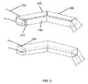
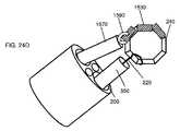
いったん自己集合磁気デバイスが組織に送達されると、デバイス240の場所を操作することが可能であることが有益である。デバイス240は、鉗子等の従来のツールを用いて操作され得るが、多くの場合、縫合糸またはワイヤ等のガイド要素220を用いて展開されたデバイス240の場所を操作することが、より単純である。図2−5に示されるように、種々の取付点が、自己集合磁気吻合デバイス240の場所および展開に対する制御を提供するために使用されることができる。例えば、図2に示されるように、自己集合に応じて、単一の遠位セグメントが、並進の自由度を提供する取付点をもたらすように、ガイド要素は、単一の遠位セグメントに結合されてもよい。図2に示される構成はまた、閉鎖力が最遠位セグメントに印加されることを可能にすることにも留意されたい。つまり、1つまたはそれを上回るセグメントが組織と絡まった状態になるか、または別様に自己集合することを妨げられる場合には、ガイド要素220による近位の引動力が、デバイス240の自己集合を完了することに役立ち得る。いったん自己集合が完了すると、デバイス240は、上記に説明されるように、ガイド要素220を用いて位置付けられ、別のデバイス(図示せず)と噛合され、吻合を形成することができる。図2に示されていないが、中実プッシャまたはガイド管等の付加的構造が、所望される場所にデバイス240を展開するために使用され得ることが想定される。送達プッシャおよびガイド管のさらなる詳細が、以下に提供される。 It is beneficial to be able to manipulate the location of the
ガイド要素220は、所望される機械的性質および生体適合性を達成するために、種々の材料から製作されることができる。ガイド要素220は、金属、例えば、ワイヤ、例えば、ステンレス鋼ワイヤまたはニッケル合金ワイヤから構築されてもよい。ガイド要素は、綿または動物製品等の天然繊維から構築されてもよい。ガイド要素は、ポリ乳酸(PLA)等の繰り返し乳酸、ラクトン、またはグリコール酸単位を含むポリマー等の生体分解性ポリマー等のポリマーから構築されてもよい。ガイド要素はまた、TyvekTM(高密度ポリエチレン繊維)またはKevlarTM(パラアラミド繊維)等の高引張強度ポリマーから構築されてもよい。ある実施形態では、ガイド要素220は、Ethicon Corp.(Somerville,NJ)から利用可能なVICRYLTM(ポリグラクチン910)縫合糸等の生体分解性縫合糸から構築される。The
ガイド要素220は、いくつかの異なる構成および取付機構を用いて自己集合磁気吻合デバイス240に結合されることができる。ガイド要素220は、単純にデバイス240に結束されてもよいか、またはガイド要素220は、接着剤、例えば、アクリレート糊を用いて、またはクリップ、ねじ、もしくはリベット等の締結具を用いてデバイス240に取り付けられることができる。デバイス240に接続されるガイド要素220の例示的構成が、図3に示され、それによって、ガイド要素220は、磁性セグメント140内のチャネル310内に置かれ、次いで、外骨格120が、ガイド要素を閉じ込める磁性セグメント140の周囲に形成されるか、または置かれる。ガイド要素220は、外骨格120における開口部330から出現し、したがって、ガイド要素220がデバイス240間の噛合と干渉しないことを確実にする。 The
図4および5等に示される他の実施形態では、ガイド要素220は、デバイス240の1つを上回る部分に取り付けられるか、またはそれらと相互作用するように構成されてもよい。図4に示されるように、ガイド要素220は、自己集合デバイス240の最遠位セグメントに取り付けられ、また、デバイス240の最近位セグメントに添着される拘束具410と相互作用してもよい。自己集合デバイス240が管腔200から展開されると、ガイド要素220への近位の力が、デバイス240の遠位および近位端を継合させ、したがって、完成した多角形を形成するであろう。ガイド要素220はまた、集合したデバイス240を留置するために使用されることもできる。図4には示されていないが、伸長マニピュレータまたはガイド管等の付加的構造が、所望される場所にデバイス240を展開するために使用され得ることが想定される。伸長マニピュレータおよびガイド管のさらなる詳細が、以下に提供される。 In other embodiments, such as shown in FIGS. 4 and 5, the
図5は、本発明の別の実施形態を示し、ガイド要素220は、自己集合デバイス240の最遠位セグメントに結合され、デバイス240の集合および留置を促進する半径方向部材510と相互作用するように構成される。図5に示されるように、ガイド要素220への近位の力は、デバイス240が自己集合することに役立つ。図5に示されるように、半径方向部材510はまた、本デバイスの中心530を確立し、これは、デバイス240が集合し、ガイド要素220が張るまで引動されると、ガイド要素220に結合される。デバイス240の中心530は、次いで、所望される場所、例えば、組織の他方の側上の反対の噛合デバイスに送達されることができる。 FIG. 5 illustrates another embodiment of the present invention where
半径方向部材510は、所望される機械的性質および生体適合性を達成するために、種々の材料から製作されることができる。半径方向部材510は、金属、例えば、ワイヤ、例えば、ステンレス鋼ワイヤまたはニッケル合金ワイヤから構築されてもよい。半径方向部材510は、綿または動物製品等の天然繊維から構築されてもよい。半径方向部材510は、ポリ乳酸(PLA)等の繰り返し乳酸、ラクトン、またはグリコール酸単位を含むポリマー等の生体分解性ポリマー等のポリマーから構築されてもよい。半径方向部材510はまた、TyvekTM(高密度ポリエチレン繊維)またはKevlarTM(パラアラミド繊維)等の高引張強度ポリマーから構築されてもよい。ある実施形態では、半径方向部材510は、Ethicon Corp.(Somerville, NJ)から利用可能なVICRYLTM(ポリグラクチン910)縫合糸等の生体分解性縫合糸から構築される。半径方向部材510は、図5において自己集合デバイス240とともに描写されているが、半径方向部材510は、概して、多角形またはリングの形状における吻合デバイスを送達および展開するために、ガイド要素220と併用され得ることを理解されたい。The
本発明のいくつかの実施形態では、デバイス、例えば、自己集合磁気デバイスが、伸長マニピュレータまたはガイド管を用いて送達される。図5は、加えて、デバイス240を展開および留置するために使用されるガイド管550を例示する。ガイド管550は、任意の生体適合性材料から構築されることができ、管腔(図5に図示せず)を含み、ガイド要素220がガイド管550を通過することを可能にし、したがって、ガイド管550から独立したガイド要素220の操作を可能にする。典型的には、ガイド管550は、半可撓性または可撓性材料から形成され、したがって、ガイド管550が、内視鏡の作業チャネル等の可撓性管腔200を介して送達されることを可能にする。カテーテルまたはポート等を通したガイド管550を用いた他の送達方法もまた、可能である。好ましい実施形態では、ガイド管550は、ガイド管550がデバイス240の強磁性セグメントに誘引されないように、非磁性材料から構築される。 In some embodiments of the invention, a device, such as a self-assembled magnetic device, is delivered using an extension manipulator or guide tube. FIG. 5 additionally illustrates a
図5に示されるように、ガイド管550は、管腔200からデバイス240を押動することに役立つ。いったんデバイス240が展開されると、デバイス240の中心530は、ガイド管550の先端を用いて留置されることができる。図5に示されるように、ガイド管550は、管腔(図示せず)を有し、ガイド要素220がガイド管550の長さに及ぶことを可能にする。図5に示されるように、ガイド管550が除去されたとき、デバイス240は、ガイド要素220に結合されたままであるため、ガイド管550が中心530から抜去された後、デバイスの中心530をガイド管550と再係合させることが可能である。つまり、ガイド管550が中心530に隣接し、ガイド要素220が半径方向部材510に対して張るまで引動される「緊密保持」(図5の底部図面)、またはガイド管550が中心530から離れて近位に移動され、ガイド要素220が管腔200と中心530との間で弛緩することを可能にされる「弛緩保持」等、中心530/ガイド管550/ガイド要素220の構成のいくつかの組み合わせに迅速にアクセスすることが可能である。「弛緩保持」位置は、2つの磁気デバイスが噛合するときに有益であり得る。「弛緩保持」位置は、延在するガイド管550を用いて組織を損傷させる懸念なく、2つの要素を結合するための最適な位置を達成するために、ユーザが患者の身体を操作することを可能にする。しかしながら、「弛緩保持」を使用してデバイス240を位置付けることが可能ではない場合では、ガイド管550を用いて中心530を再係合させ、デバイス240を移動することが可能である(図18A−18Fもまた参照)。他の構成もまた可能であることに留意されたい。例えば、デバイス240は、磁気吻合デバイスの2つのセグメントに結合される第1および第2のガイド要素220を有し、展開されたデバイス240を操向、回転、または操作するための手段を提供してもよい。 As shown in FIG. 5, the
図4の管腔200の断面が、図6に示され、図5の管腔200の断面が、図7に示される。図6および7では、自己集合デバイス240は、実質的に直線状の構成において示され、それによって、磁性セグメント140(図6および7では隠されている)は、間隙620によって分離されるが、磁性セグメント140は、外骨格120によってともに保たれる。外骨格120は弾性材料から作製されるため、デバイス240は、図6および7に示される実質的に直線状の構成に保持された後、自然に自己集合するであろう。図6に示されるように、ガイド要素220は、デバイスの遠位および近位端に結合され、ガイド要素220は、管腔200の長さに延設し、デバイス240を過ぎて近位に延在する。図7に示されるように、ガイド要素220は、デバイス240に結合されながら管腔200内に収容される半径方向部材510に結合される。デバイス240が、例えば、ガイド管550(図6または7に図示せず)を用いて管腔240から押動されると、デバイス240は、図5に示されるように自己集合し、中心530は、半径方向部材510およびガイド要素220の共通場所として画定される。 A cross section of the
図8は、本発明のデバイス、システム、および方法と併用され得るテンショナ部材700である。本明細書にさらに詳細に説明されるであろうように、テンショナ700は、本開示に準拠する磁気デバイス240の送達および自己閉鎖中に1つまたはそれを上回るガイド要素を張るように保つように構成される。先に説明されるように、いったん自己集合磁気デバイスが組織に送達されると、デバイス240の場所を操作することが可能であることが有益である。デバイス240は、鉗子等の従来のツールを用いて操作され得るが、多くの場合、1つまたはそれを上回るガイド要素220を用いて展開されたデバイス240の場所を操作することが、より単純である。図8−15に示される実施形態では、有意な張力が、磁性セグメント140に結合される1つまたはそれを上回るガイド要素にわたるハンドヘルド制御をユーザまたはオペレータに提供するように構成される、テンショナ700を介して1つまたはそれを上回る磁性セグメント140に印加されることができる。例えば、図8に示されるように、テンショナ700は、制御部材702−710を含み、それぞれ、それらに結合されるガイド要素221−224の張力に対する制御をユーザに提供し、それによって、ガイド要素が結合される磁性セグメントに張力が印加されることを可能にする。示されるように、制御部材702−710は、概して、例えば、ユーザの指を受容するためにリングの形態であってもよい。本明細書にさらに詳細に説明されるであろうように、制御部材はそれぞれ、個別に操作され、さらに、係止状態と係止解除状態との間で遷移してもよい。張力の印加は、概して、自己閉鎖または自己開放中に緩みを排除し、ガイド要素を可視化または他の手技の進路から回避させ、さらに、送達状態から展開された状態への遷移中に本デバイスを安定させる。 FIG. 8 is a
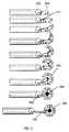
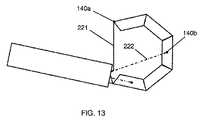
本明細書に説明される内視鏡、トロカール、または他の送達デバイスの管腔200の断面が、図9に示される。図9では、自己集合デバイス240は、実質的に直線状の構成において示される。先に説明されるように、種々の取付点が、自己集合磁気吻合デバイス240の場所および展開に対する制御を提供するために使用されることができる。図9−15に示されるように、例えば、4つのガイド要素221−224が、それぞれ、デバイス240の4つの別個のセグメント140a−140dに結合されてもよい。故に、制御部材の操作に応じて、ユーザがガイド要素の張力を印加(または弛緩)し、したがって、それに結合された関連付けられる磁性セグメントを操作し得るように、ガイド要素221、222、223、および224は、それぞれ、制御部材702、704、706、および708に結合される。示されるように、ガイド要素221は、最遠位端部セグメント140aに結合され、ガイド要素222および223は、それぞれ、セグメント140bおよび140cに結合され、ガイド要素224は、最近位端部セグメント140dに結合される。 A cross section of
ガイド要素221−224は、所望される機械的性質および生体適合性を達成するために、種々の材料から製作されることができる。ガイド要素221−224は、金属、例えば、ワイヤ、例えば、ステンレス鋼ワイヤまたはニッケル合金ワイヤから構築されてもよい。ガイド要素は、綿または動物製品等の天然繊維から構築されてもよい。ガイド要素は、ポリ乳酸(PLA)等の繰り返し乳酸、ラクトン、またはグリコール酸単位を含むポリマー等の生体分解性ポリマー等のポリマーから構築されてもよい。ガイド要素はまた、TyvekTM(高密度ポリエチレン繊維)またはKevlarTM(パラアラミド繊維)等の高引張強度ポリマーから構築されてもよい。ある実施形態では、ガイド要素221−224は、Ethicon Corp.(Somerville,NJ)から利用可能なVICRYLTM(ポリグラクチン910)縫合糸等の生体分解性縫合糸から構築される。Guide elements 221-224 can be made from a variety of materials to achieve the desired mechanical and biocompatibility properties. The guide elements 221-224 may be constructed from a metal, such as a wire, such as a stainless steel wire or a nickel alloy wire. The guide element may be constructed from natural fibers such as cotton or animal products. The guide element may be constructed from a polymer such as a biodegradable polymer such as a polymer containing repeating lactic acid, lactone, or glycolic acid units such as polylactic acid (PLA). The guide element may also be constructed from a high tensile strength polymer such as Tyvek™ (high density polyethylene fiber) or Kevlar™ (para-aramid fiber). In some embodiments, guide elements 221-224 may be connected to Ethicon Corp. Constructed from biodegradable sutures such as VICRYL™ (Polyglactin 910) sutures available from (Somerville, NJ).
ガイド要素221−224は、いくつかの異なる構成および取付機構を用いて自己集合磁気吻合デバイス240のセグメント140a−140dに結合されることができる。ガイド要素は、単純にデバイス240に結束されてもよいか、またはガイド要素221−224は、接着剤、例えば、アクリレート糊を用いて、またはクリップ、ねじ、もしくはリベット等の締結具を用いてデバイス240に取り付けられることができる。 Guide elements 221-224 can be coupled to
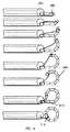
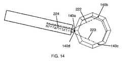
図10−14は、テンショナおよび複数のガイド要素を用いた自己閉鎖磁気吻合デバイスの展開を描写する。デバイス240の送達および展開は、例えば、少なくともガイド要素221への張力を用いてプッシャを前進させることによって開始される。磁性セグメント140が管腔200から排出されるにつれて、ガイド要素221への張力は、最遠位端部セグメント140aを押勢し、デバイス240の集合を開始する。さらに、ガイド要素224への張力は、デバイス240が集合するように、最近位端部セグメント140dを押勢し、最遠位端部セグメント140aと接触させる。ユーザは、次いで、それぞれのガイド要素に張力を維持するように、テンショナ700上にそれぞれの制御部材702−708を係止してもよい。例えば、教示されるガイド要素221は、不注意な捕捉から組織襞を偏向させるだけではなく、従来はデバイス240の8つの誘引性留め継ぎによって確実にされていた腸管腔内に緊密な「旋回半径」を確実にする潜在性を有する。いったん最遠位および最近位端部セグメント140a、140dが、それらの捕捉距離内でガイド要素221、224によって引動されると、セグメント140aおよび140dの近接範囲誘引が、図14に示されるように、他方の反発力より優勢になり、リング間隙を閉鎖することができる。リングは、完全に長円形あってもよいが、閉鎖される。この時点で、他のガイド要素222および223は、多角形を引締し、任意の偏向または不整合を修正するために使用されてもよい。ガイド要素221−224を係止することによって、ガイド要素の暴露される長さの側方偏向が、適切な張力を印加することができる。いったん展開されると、張力下のガイドワイヤは、磁気セットを整合および噛合させるために使用されることができる。これは、蛍光透視法を使用して可視化されてもよい。 FIGS. 10-14 depict the deployment of a self-closing magnetic anastomosis device using a tensioner and a plurality of guide elements. Delivery and deployment of the
図15は、図14の展開された自己閉鎖磁気吻合デバイス240の操作を描写する。いったん自己集合が完了すると、デバイス240は、上記に説明されるように、ガイド要素221−224を用いて位置付けられ、別のデバイス(図示せず)と噛合され、吻合を形成することができる。さらに、中実プッシャまたはガイド管が、所望される場所にデバイス240を展開するために使用されることができる。 FIG. 15 depicts the operation of the deployed self-closing
図16は、吻合を形成するための本発明のデバイス、システム、および方法と併用するために好適な自己閉鎖磁気吻合デバイスを描写する。本デバイスは、磁性セグメント140を相互に結合するために、ガイド要素220と類似し得る、中心部材を含む。中心部材もまた、デバイス240の留置を促進し得る。図16に示されるように、自己閉鎖デバイス240は、概して、磁性セグメント140を通して一連の管腔を含み、中心部材が磁性セグメント140を通して延設されることを可能にし、集合を促進してもよい。中心部材は、所望される機械的性質および生体適合性を達成するために、種々の材料から製作されることができる。例えば、中心部材は、金属、例えば、ワイヤ、例えば、ステンレス鋼ワイヤまたはニッケル合金ワイヤから構築されてもよい。いくつかの実施形態では、中心部材は、例えば、体温に暴露されると、所望される形状、例えば、円をとるように熱的にプログラムされてもよい。故に、中心部材は、ステンレス鋼またはニチノールワイヤ等のワイヤであってもよい。他の実施形態では、中心部材は、縫合糸から構築されてもよく、中心部材は、綿または動物製品等の天然繊維から、またはポリ乳酸(PLA)等の繰り返し乳酸、ラクトン、またはグリコール酸単位を含むポリマー等の生体分解性ポリマー等のポリマーから構築されてもよい。中心部材はまた、TyvekTM(高密度ポリエチレン繊維)またはKevlarTM(パラアラミド繊維)等の高引張強度ポリマーから構築されてもよい。ある実施形態では、中心部材は、Ethicon Corp.(Somerville,NJ)から利用可能なVICRYLTM(ポリグラクチン910)縫合糸等の生体分解性縫合糸から構築される。FIG. 16 depicts a self-closing magnetic anastomosis device suitable for use with the devices, systems, and methods of the present invention for forming an anastomosis. The device includes a central member that can be similar to the
いくつかの実施形態では、中心部材は、デバイス240が自己集合した後に留置を指向するために使用されることができる。いくつかの実施形態では、外骨格120に関して説明されるものと類似する様式において、付加的な機械的特徴が、磁性セグメント140間に結合され、送達および展開中の面外運動を最小限にすることができる。 In some embodiments, the central member can be used to direct placement after the
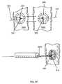
他の実施形態では、磁気自己集合吻合デバイスは、図17に示されるように、単純な送達カテーテル870を用いて送達されることができる。送達カテーテル870は、単純に、デバイス240を送達するための第1の管腔200と、所望される吻合の場所に送達カテーテル870を誘導するための第2の管腔820とを有する。図17に示されるように、送達カテーテル870は、送達場所へのガイドワイヤ810に沿って乗設する。第2の管腔820、例えば、ガイド管腔は、送達カテーテル870の長さに延設してもよいか、またはこれは、送達カテーテル870の長さの一部のみに延設してもよい。 In other embodiments, the magnetic self-assembling anastomosis device can be delivered using a
他のデバイスもまた、ガイド管550に取って代わるように使用されることができる。例えば、図17に示されるように、可撓性プッシャ850が、デバイス240を吻合の所望される場所に送達するために使用されることができる。図17に示されるように、デバイス240は、ガイド要素220に結合され、ガイド要素220がデバイス240を集合させ、デバイス240の留置を指向するために使用されることを可能にしてもよい。しかしながら、いくつかの実施形態では、ガイド要素220は、存在しない場合がある。他の実施形態では、デバイス240は、半径方向部材510(図17に図示せず)を含み、可撓性プッシャ850は、いったんデバイス240が展開されると、プッシャの先端が中心530を所望される場所に指向することを可能にする取付点を有してもよい。可撓性プッシャは、生体適合性プラスチック、例えば、PTFE等の半可撓性かつ生体適合性材料、好ましくは、非磁性材料から作製されることができる。 Other devices can also be used to replace the
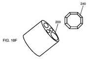
ガイド管550と、ガイド要素220と、デバイス240との間の相互作用が、図18A−18Fにより詳細に例証される。図18Aに示されるように、デバイス240は、ガイド管550の管腔を通して延設する、ガイド要素220に結合される。図18A−18Fのデバイス240は、8つの磁性セグメントを伴う自己集合吻合デバイスで達成されるであろうように、八角形として描写されるが、しかしながら、デバイス240は、任意のリングまたは多角形であり、自己集合するか、またはそうではない場合がある。図18Bに示されるように、ガイド管550は、内視鏡の作業チャネルであり得る、管腔200を介して送達される。ガイド管550はまた、トロカール、カテーテル、または細針吸引デバイスを介して送達されることもできる。 The interaction between
送達後、デバイス240は、図18Bに示されるように、近位の力をガイド要素220に印加することによって、ガイド管550と接触させられることができる。いったんガイド管550がデバイス240に接触すると、図18C、すなわち、「緊密保持」に示されるように、ガイド管550を並進させることによって、デバイス240を操作することが可能である。いくつかの実施形態では、また、ガイド管550を回転させることによって、デバイス240を回転させることも可能である(図示せず)。故に、ガイド管550は、それを通ってガイド管550が受容される送達デバイス(例えば、内視鏡、トロカール、カニューレ、カテーテル、または針の作業チャネルもしくは管腔200)に対して独立して並進可能かつ回転可能であり得る。同様に、ガイド管550は、1つまたはそれを上回るガイド要素220を用いてデバイス240に結合されるため、デバイス240はさらに、送達デバイス(例えば、内視鏡、トロカール、カニューレ、カテーテル、針等)から独立して位置付けられるか、または操作されることができる。したがって、デバイス240は、送達またはアクセスデバイスから独立して並進可能および/または回転可能であり得る。ガイド管550を使用して、デバイス240は、大まかな場所に留置されることができ、その点で、図18Dに示されるように、ガイド要素220がデバイス240に結合されたまま、ガイド管550がデバイス240から抜去される。上記に議論されるように、この「弛緩保持」構成は、最適な位置を達成するために、ユーザが患者およびデバイス240を操作することを可能にするが、ガイド管550は、進路から回避される。加えて、必要とされる場合、ガイド管550は、図18Cのように、デバイス240に戻され、さらなる操作を可能にすることができる。いったんデバイス240が定位置に来ると、ガイド要素220は、図18Eに示されるように、例えば、切断要素930を使用して、デバイス240から結合解除されることができる。切断要素930は、剪刀型器具として描写されているが、しかしながら、鋭い刃または焼灼ワイヤ等の任意の切断ツールもまた、機能するであろう。いったんデバイス240がガイド要素220から結合解除されると、送達器具は、図18Fに示されるように、デバイス240から除去されることができる。 After delivery, the
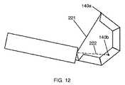
別の実施形態では、デバイス240は、腹腔鏡手技等において使用されるトロカール1050を通して留置される、送達カテーテル1030を含むシステムを用いて組織に送達されることができる。図19に示されるように、それに取り付けられるガイド要素220を伴う自己集合デバイス240は、ガイド要素220が延設され得る管腔を有する伸長マニピュレータ1070を用いて送達カテーテル1030を通して押動されることができる。上記の図2−5および9−15に類似して、ガイド要素220は、デバイス240との1つもしくは複数の接続点を有してもよいか、または本デバイスは、半径方向要素510(図19に図示せず)を含んでもよい。加えて、ガイド管550送達に関して上記に説明されるように、伸長マニピュレータ1070はまた、デバイス240がガイド要素220に結合されたまま、伸長マニピュレータ1070をデバイス240にもたらし、次いで、伸長マニピュレータ1070をデバイス240から後退させることによって、「緊密保持」および「弛緩保持」の両方の可撓性を提供する。 In another embodiment, the
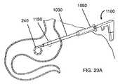
トロカール1050を使用すると、デバイス240を種々の解剖学的標的に送達することが単純かつ迅速となる。図20Aに示されるように、トロカール1050を用いて身体に進入する(または別のポートを提供する)だけに過ぎず、その点において、送達カテーテル1030が、組織に(またはそれを通して)もたらされ、デバイス240は、伸長マニピュレータ1070(図20Aまたは20Bに図示せず)を用いて展開されることができる。伸長マニピュレータ1070は、剛性金属またはポリマーから構築されてもよく、伸長マニピュレータ1070がトロカール1050および送達カテーテル1030を通して操作されることを可能にする。典型的には、送達は、別個のトロカールまたはポートを通して術野にもたらされる腹腔鏡(図示せず)を用いて可視化されるであろう。 Using the
いくつかの実施形態では、図20B等に示されるように、2つの別個の腹腔鏡送達デバイス1100が、噛合デバイス240を展開し、吻合を形成するために使用されることができる。他の実施形態では、単一の腹腔鏡送達デバイス1100が、第1のデバイス240を送達するために使用されることができ、第2のデバイスが、例えば、上記に議論され、図18A−18Fに示されるように、内視鏡等を用いる等、別の送達方法を用いて送達されることができる。他の実施形態では、第1のデバイス240が、腹腔鏡送達デバイス1100を用いて送達され、腹腔鏡送達デバイス1100は、続けて、除去され、第1のデバイスと噛合させるための第2のデバイス240を再装填されることができる。 In some embodiments, as shown in FIG. 20B, etc., two separate
第1および第2のデバイス240の噛合が、図21−26にさらに詳細に示される。噛合は、例えば、内視鏡、送達カテーテル、トロカール1050を用いるか、または別のポートを介した送達方法にかかわらず同様に機能する。図21に示されるように、それぞれ、ガイド要素220に結合される2つのデバイス240は、吻合が形成されるべき組織1210および1220の対向する側面にもたらされる。いったん2つのデバイス240が近接させられると、これらのデバイス240は、噛合し、組織1210および1220をともに合わせる。時間が経つと、デバイス240のサイズおよび形状の吻合が形成され、本デバイスは、組織から脱落し得る。半径方向部材510を備えるデバイスが、例えば、図22に示されるように吻合を作成するために使用されるとき、類似する技法が、使用される。図21および22は、伸長マニピュレータ1070を伴うデバイス240の操作を描写しているが、デバイス240の一方または両方は、上記に説明されるように、ガイド管550を用いて送達されることができる。加えて、デバイス240は、伸長マニピュレータ1070を用いて本デバイスに対して堅く位置付けられるように示されているが、伸長マニピュレータ1070の干渉を伴わずにデバイス240が噛合することを可能にするために、「弛緩保持」構成を使用することが有益であり得ることを理解されたい。磁気吻合送達方法(例えば、内視鏡、送達カテーテル、腹腔鏡)の複数の組み合わせが使用され得ることを理解されたい。 The engagement of the first and
開示される磁気吻合システムの別の利益は、噛合したデバイス240が、デバイス240間に閉じ込められた組織への血流を迅速に停止させるために十分な圧縮力を生成することである。図20Aおよび20Bに示されるように、外科医は、器官(例えば、胃、小腸、腸)の内部に迅速にアクセスし、器官に切開部1150を作製し、次いで、切開部1150を通してデバイス240を送達し、次いで、デバイス240を展開してもよく、したがって、デバイス240は、切開部を外接する。いったん噛合デバイス240が送達されると、切開部への血流は、迅速に切り離される。したがって、外科医は、器官における切開部1150を閉鎖する必要がなく、本手技を迅速化し、殆どの器具(例えば、腹腔鏡ステープラ)を要求しない。デバイス240を用いて切開部1150を外接する技法は、両方のデバイス240に対して行われることができるか、または1つのデバイス240は、例えば、内視鏡を用いて送達され、第2のデバイス240は、切開部1150を通して送達されることができる。 Another benefit of the disclosed magnetic anastomosis system is that the articulated
いくつかの実施形態では、2つの噛合磁気吻合デバイスは、例えば、内視鏡または腹腔鏡カメラを使用して、直接可視化されることができる。他の事例では、2つの噛合磁気吻合デバイスは、超音波または蛍光透視法等の別の医療撮像技法を用いて監視されることができる。いくつかの実施形態では、可視化は、送達デバイスに提供されるであろう。いくつかの実施形態では、可視化は、別個のデバイスを用いて達成されるであろう。染料、造影剤、および気体送達等の当分野で公知の他の技法もまた、噛合デバイスの可視化を補助するために使用されてもよい。 In some embodiments, the two biting magnetic anastomosis devices can be directly visualized using, for example, an endoscope or a laparoscopic camera. In other cases, the two biting magnetic anastomosis devices can be monitored using another medical imaging technique such as ultrasound or fluoroscopy. In some embodiments, visualization will be provided on the delivery device. In some embodiments, visualization will be achieved using a separate device. Other techniques known in the art such as dyes, contrast agents, and gas delivery may also be used to aid visualization of the bite device.
ガイド管550または伸長マニピュレータ1070を用いてデバイス240を操作することに加えて、いくつかの事例では、図23Aおよび23Bに示されるように、本手技中に患者の身体を能動的に操作することが有益であり得る。図23Aは、例えば、2つの腹腔鏡送達デバイス1100が、例えば、図20Bに示されるように、2つのデバイス240を継合されるべき2つの組織に送達するために使用される手技であり得る。組織がデバイス240に対して近接近するか、または別様に優れた整合状態にあるように、図23Aに示されるように、患者が仰向けであるときに組織を可視化することが容易であり得るが、図23Bに示されるように、患者を操作することによって2つの組織を継合することも容易であり得る。いくつかの事例では、以下により詳細に議論されるように、患者の操作の有無にかかわらず、デバイス240または組織に付加質量を追加し、デバイス240の整合を改良することもまた有益であり得る。患者の操作中、多くの場合、磁気デバイスがその最低エネルギー構成を見出し得るように、伸長マニピュレータ1070をデバイス240から後退させる、すなわち、「弛緩保持」位置をとることが有益である。しかしながら、デバイス240は、依然としてガイド要素220に結合されているため、必要に応じて一方または両方のデバイス240を再位置付けすることが非常に容易である。 In addition to manipulating
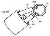
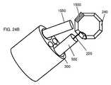
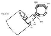
磁気吻合デバイスへの重量を変更する(質量を追加する)ための一方法が、図24A−24Dに描写される。図18A−18Fに示されるものに類似する構成を使用して、ガイド要素220に結合されるデバイス240が、管腔200(例えば、内視鏡の作業チャネル)を通して送達されるガイド管550を使用して組織に送達される。いったんデバイス240がおおよその位置に来ると、補助カテーテル1550が、デバイス240にもたらされ、取り外し可能な重り1530が本デバイスに取り付けられることを可能にする。いくつかの実施形態では、取り外し可能な重り1530は、強磁性であるため、それらは、本デバイスにおける磁性セグメント140に自然に誘引される。そのような取り外し可能な重り1530は、生体適合性を向上させるために、例えば、PTFE等のポリマーを用いて取り外し可能な重りをコーティングすることによって、コーティングされてもよい。代替実施形態では、取り外し可能な重り1530は、生体適合性接着剤またはゲルを用いてデバイス240に結合されてもよい。いったん取り外し可能な重り1530がデバイス240に送達されると、補助カテーテル1550は、図24Bに示されるように、本デバイスから後退される。取り外し可能な重り1530を伴う最終デバイス240が、図24Cに示されるように出現し得る。デバイス240に提供される付加的重量は、デバイス240を操作することをより容易にし、隣接する組織上に噛合デバイスが接触する際に本デバイスを補助するであろう。図24Cに示されるように、ガイド要素220および/またはガイド管550は、重り付きデバイス240を操作および留置するために使用されることができる。加えて、患者は、図23Aおよび23Bに関して上記に説明されるように、重り付きデバイス240が別のデバイスと噛合することに役立つように移動されてもよい。最後に、いったんデバイス240が適切な位置を達成すると、取り外し可能な重り1530は、補助マニピュレータ1570を用いてデバイス240から除去され、噛合したデバイスが過剰な重量に起因してその最終位置から移動しないことを確実にすることができる。 One method for changing the weight (adding mass) to the magnetic anastomosis device is depicted in FIGS. 24A-24D. Using a configuration similar to that shown in FIGS. 18A-18F, the
しかしながら、本発明のデバイス240に付加的重量を追加するための方法は、図24A−24Dに示される実施形態に限定されない。例えば、取り外し可能な重りは、上記に説明される機能性を達成するために、トロカールまたは他のポートを通して送達されることができる。代替実施形態では、バルーンカテーテル(図示せず)が、デバイス240またはデバイス240の近傍に送達され、次いで、液体で充填され、デバイス240の移動を促進することができる。そのような技法は、特に、小腸等、バルーンカテーテルを使用して容易にアクセスおよび充填され得る管腔内に位置するデバイス240を位置付ける際に有用である。 However, the method for adding additional weight to the
上記に説明されるデバイスおよび方法は、単独で使用される必要はない。例えば、図25に示されるように、第1のデバイス240は、内視鏡1650を用いて送達され、第2のデバイス240は、ガイドワイヤ1610を介して吻合に指向される送達カテーテル1630を用いて送達されてもよい。いくつかの実施形態では、ガイドワイヤ1610は、独立して吻合の部位に送達されてもよく、他の実施形態では、ガイドワイヤ1610は、第1のデバイス240を送達した同一のツールを使用して展開されてもよい。例えば、送達カテーテル1630が必ず第1のデバイス240の場所に指向されるように、第1のデバイス240が、展開され、切開部が、本デバイスの環状中間部を通して作製され、ガイドワイヤが、そこを通して展開されてもよい。 The devices and methods described above need not be used alone. For example, as shown in FIG. 25, the
継合されるべきデバイスはまた、図26に示されるように、独立した外科手術操作、例えば、腹腔鏡補助と整合するように誘導されてもよい。操作は、デバイス240、または器官、またはその両方に対してであってもよい。例えば、図26に示される実施形態では、第1および第2のデバイス240は、それぞれ、内視鏡1650および送達カテーテル1630を用いて送達される。デバイス240は、腹腔鏡1720を使用して組織を通して可視であるため、例えば、第1のデバイス240を有する腸のループを握持し、これを第2のデバイス240と整合させることによって、腹腔鏡把持装置1740を用いて腸を操作し、2つのセグメントをともに合わせることが容易である。 The device to be joined may also be guided to align with an independent surgical operation, eg, laparoscopic assistance, as shown in FIG. The operation may be on
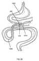
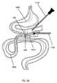
したがって、本発明のデバイスおよび方法を使用して、胃腸管内の組織および器官の間に吻合を作成することが可能である。内視鏡技法および腹腔鏡技法を使用して、本発明のデバイスは、図27に示されるように、胃、小腸、胆嚢、および結腸等の胃腸管の種々の器官の間の種々の吻合の作成を可能にする。そのような技法は、肥満および糖尿病等の疾病の管理のために使用されることができる、またはそのような技法は、癌等の疾病の後で機能を向上させるために使用されることができる。そのような技法はまた、修復のために、例えば、図28に示されるように、疾患結腸の一部が除去された後に健康な結腸の部分を接続するために使用されることもできる。 Thus, the devices and methods of the present invention can be used to create an anastomosis between tissues and organs in the gastrointestinal tract. Using endoscopic and laparoscopic techniques, the device of the present invention can be used for various anastomoses between various organs of the gastrointestinal tract, such as the stomach, small intestine, gallbladder, and colon, as shown in FIG. Allows creation. Such techniques can be used for the management of diseases such as obesity and diabetes, or such techniques can be used to improve function after diseases such as cancer. . Such techniques can also be used for repair, eg, to connect a healthy colon part after the diseased colon part has been removed, as shown in FIG.
本明細書に説明されるデバイス、システム、および方法は、隣接する組織または器官の間に吻合を形成することを対象とする。特定の実施形態では、組織は、例えば、胃および胆嚢、小腸および胆嚢、胃および十二指腸、または回腸および結腸等の隣接する胃腸器官である。隣接する組織、例えば、隣接する器官または同一器官の異なる領域に展開されると、結合された磁気デバイスのペアは、外科手術的に開放され得る、またはさらなる介入を伴わずに吻合を形成することを可能にされ得る圧縮リングを作成する。ペアのデバイスが単独で残されると、組織に対する圧縮力が、脈管を圧潰し、組織内の流体を押出し、さらに、デバイス間の距離を低減させ、磁気誘引を増加させる。時間が経つと、結合されたデバイスは、最終的に完全に結合し、脱落し、形成された吻合を残す。 The devices, systems, and methods described herein are directed to forming an anastomosis between adjacent tissues or organs. In certain embodiments, the tissue is an adjacent gastrointestinal organ such as, for example, the stomach and gallbladder, the small intestine and gallbladder, the stomach and duodenum, or the ileum and colon. When deployed in adjacent tissue, e.g., adjacent organs or different regions of the same organ, the pair of coupled magnetic devices can be surgically opened or form an anastomosis without further intervention Create a compression ring that can be enabled. When the pair of devices is left alone, the compressive force on the tissue will collapse the vessels, push the fluid in the tissue, and further reduce the distance between the devices and increase magnetic attraction. Over time, the bonded device eventually becomes fully bonded and falls off, leaving the anastomosis formed.
いくつかの用途では、磁気デバイスのペアは、血管吻合を作成する、または心臓病を処置するために使用され得ることに留意されたい。例えば、磁気吻合結合が、磁気デバイスを用いて隣接する血管間に形成されることができる。例えば、磁気デバイスのペアが、カテーテル等の血管送達デバイスを用いて送達されることができる。 It should be noted that in some applications, a pair of magnetic devices can be used to create a vascular anastomosis or treat a heart disease. For example, a magnetic anastomosis bond can be formed between adjacent blood vessels using a magnetic device. For example, a pair of magnetic devices can be delivered using a vascular delivery device such as a catheter.
(参照による組み込み)
特許、特許出願、特許公開、雑誌、書籍、論文、ウェブコンテンツ等の他の文書が、本開示全体を通して参照および引用されている。全てのそのような文書は、あらゆる目的のために、本明細書に参照することによってその全体として本明細書に組み込まれる。(Embedding by reference)
Other documents such as patents, patent applications, patent publications, magazines, books, papers, web content, etc. are referenced and cited throughout this disclosure. All such documents are hereby incorporated by reference in their entirety for all purposes.
(均等物)
本発明は、その精神または本質的な特性から逸脱することなく、他の具体的形態において具現化されてもよい。前述の実施形態は、したがって、本明細書に説明される発明を制限するものではなく、あらゆる点で例証的であると見なされる。本発明の範囲は、したがって、前述の説明ではなく、添付される請求項によって示され、請求項の均等物の意味および範囲に該当する全ての変更は、したがって、その中に包含されることが意図される。
(Equivalent)
The present invention may be embodied in other specific forms without departing from its spirit or essential characteristics. The foregoing embodiments are therefore not to be construed as limiting the invention described herein and are to be considered in all respects illustrative. The scope of the invention is, therefore, indicated by the appended claims rather than by the foregoing description, and all modifications that fall within the meaning and scope of the equivalents of a claim are thus encompassed therein. Intended.
Claims (110)
Translated fromJapanese幾何学形状に自己集合する、磁性セグメントと、
前記多角形またはリングに結合され、前記多角形またはリングの中心点に近接して相互に結合される、半径方向部材と、を備える、磁気圧縮吻合デバイス。A magnetic compression anastomosis device shaped as a polygon or ring,
Magnetic segments that self-assemble into geometric shapes,
A magnetic compression anastomosis device comprising a radial member coupled to the polygon or ring and coupled to each other proximate to a center point of the polygon or ring.
対象者体内の解剖学的構造にアクセスを提供するように構成される、アクセスデバイスと、
前記デバイス内に嵌合するように構成され、前記デバイスに対して独立して並進可能かつ回転可能である、伸長マニピュレータと、
多角形またはリングとして成形される磁気圧縮吻合デバイスであって、前記多角形またはリングに結合され、前記多角形またはリングの中心点に近接して相互に結合される、半径方向部材を備え、前記伸長マニピュレータは、少なくとも1つの半径方向部材に結合可能であり、それによって、前記伸長マニピュレータが、磁気圧縮吻合デバイスの留置を指向することを可能にする、磁気圧縮吻合デバイスと、を備える、システム。A system for forming an anastomosis,
An access device configured to provide access to anatomy within the subject's body;
An extension manipulator configured to fit within the device and independently translatable and rotatable with respect to the device;
A magnetic compression anastomosis device shaped as a polygon or ring, comprising a radial member coupled to the polygon or ring and coupled to each other proximate to a center point of the polygon or ring; An extension manipulator is coupleable to at least one radial member, thereby comprising a magnetic compression anastomosis device that allows the extension manipulator to direct placement of the magnetic compression anastomosis device.
磁性セグメントを備える、自己集合磁気圧縮デバイスと、
近位および遠位端を有し、前記磁気圧縮デバイスに結合される、少なくとも1つのガイド要素と、
中心管腔を有するガイド管であって、前記ガイド要素は、前記管腔内に位置付けられ、前記ガイド要素の並進が、前記磁気圧縮デバイスの並進を引き起こす、ガイド管と、を備える、磁気圧縮吻合システム。A magnetic compression anastomosis system,
A self-assembled magnetic compression device comprising magnetic segments;
At least one guide element having proximal and distal ends and coupled to the magnetic compression device;
A magnetic compression anastomosis comprising a guide tube having a central lumen, wherein the guide element is positioned within the lumen and translation of the guide element causes translation of the magnetic compression device system.
対象者体内の解剖学的構造にアクセスを提供するように構成される、トロカールと、
前記トロカール内に嵌合するように構成され、前記トロカールに対して独立して並進可能かつ回転可能である、伸長マニピュレータと、
多角形またはリングとして成形される磁気圧縮吻合デバイスであって、前記多角形またはリングに結合されるガイド要素を備え、それによって、前記伸長マニピュレータが、前記磁気圧縮吻合デバイスの留置を指向することを可能にする、磁気圧縮吻合デバイスと、を備える、システム。A system for forming an anastomosis,
A trocar configured to provide access to the anatomy within the subject's body; and
An elongate manipulator configured to fit within the trocar and independently translatable and rotatable with respect to the trocar;
A magnetic compression anastomosis device shaped as a polygon or ring, comprising a guide element coupled to the polygon or ring, whereby the extension manipulator directs the placement of the magnetic compression anastomosis device A system comprising: a magnetic compression anastomosis device.
幾何学形状に自己集合するように構成される磁性セグメントを備える、自己集合磁気圧縮デバイスと、
近位および遠位端を有し、前記磁気圧縮デバイスに結合される、ガイド要素と、
中心管腔を有するガイド管であって、前記ガイド要素は、前記管腔内に位置付けられ、前記ガイド要素の並進は、前記磁気圧縮デバイスの並進を引き起こす、ガイド管と、を備える、磁気圧縮吻合システム。A magnetic compression anastomosis system,
A self-assembled magnetic compression device comprising magnetic segments configured to self-assemble into geometric shapes;
A guide element having proximal and distal ends and coupled to the magnetic compression device;
A magnetic compression anastomosis comprising a guide tube having a central lumen, wherein the guide element is positioned within the lumen, and translation of the guide element causes translation of the magnetic compression device system.
磁性セグメントを備える、自己集合磁気圧縮デバイスと、
取り外し可能な重りと、
前記取り外し可能な重りを前記磁気圧縮デバイスに送達するように構成される、送達要素と、を備える、磁気圧縮吻合システム。A magnetic compression anastomosis system,
A self-assembled magnetic compression device comprising magnetic segments;
With removable weights,
A magnetic compression anastomosis system comprising a delivery element configured to deliver the removable weight to the magnetic compression device.
磁性セグメントを備える、自己集合磁気圧縮デバイスと、
膨張すると、解剖学的管腔内に自己集合磁気圧縮デバイスを保定するように適合される、バルーンカテーテルと、を備える、磁気圧縮吻合システム。A magnetic compression anastomosis system,
A self-assembled magnetic compression device comprising magnetic segments;
A magnetic compression anastomosis system comprising a balloon catheter adapted to retain a self-assembling magnetic compression device within an anatomical lumen when inflated.
第1の磁気圧縮吻合デバイスに結合される第1の伸長マニピュレータを組織に送達するステップであって、前記第1の磁気圧縮吻合デバイスは、多角形またはリングとして成形され、そして前記多角形またはリングに結合され、かつ前記多角形またはリングの中心点に近接して相互に結合される、半径方向部材を備える、ステップと、
第2の磁気圧縮吻合デバイスに結合される第2の伸長マニピュレータを前記組織に送達するステップと、
前記第1および第2の磁気圧縮吻合デバイスが前記組織を結合および圧縮するように、前記第1の磁気圧縮吻合デバイスを前記第2の磁気圧縮吻合デバイスに近接させるステップと、を含む、方法。A method for creating an anastomosis in a tissue, comprising:
Delivering to a tissue a first elongate manipulator coupled to a first magnetic compression anastomosis device, wherein the first magnetic compression anastomosis device is shaped as a polygon or ring, and the polygon or ring And comprising radial members coupled to each other proximate to a center point of the polygon or ring;
Delivering a second extension manipulator coupled to a second magnetic compression anastomosis device to the tissue;
Bringing the first magnetic compression anastomosis device proximate to the second magnetic compression anastomosis device such that the first and second magnetic compression anastomosis devices join and compress the tissue.
第1の磁気圧縮吻合デバイスに結合される第1の伸長マニピュレータを組織に送達するステップであって、前記第1の磁気圧縮吻合デバイスは、多角形またはリングとして成形され、ガイド要素を用いて前記第1の伸長マニピュレータに結合される、ステップと、
第2の磁気圧縮吻合デバイスを前記組織に送達するステップと、
前記第1および第2の磁気圧縮吻合デバイスが前記組織を結合および圧縮するように、前記第1の磁気圧縮吻合デバイスを前記第2の磁気圧縮吻合デバイスに近接させるステップと、を含む、方法。A method for creating an anastomosis in a tissue, comprising:
Delivering to a tissue a first elongate manipulator coupled to a first magnetic compression anastomosis device, wherein the first magnetic compression anastomosis device is shaped as a polygon or a ring and uses a guide element to A step coupled to the first extension manipulator;
Delivering a second magnetic compression anastomosis device to the tissue;
Bringing the first magnetic compression anastomosis device proximate to the second magnetic compression anastomosis device such that the first and second magnetic compression anastomosis devices join and compress the tissue.
ガイド要素に結合される第1の磁気圧縮デバイスを、送達管腔を通して組織に送達するステップと、
前記送達管腔内に配置されるガイド管を用いて前記第1の磁気圧縮デバイスを位置付けるステップであって、前記ガイド管は、中心管腔を有し、前記ガイド要素は、前記中心管腔内に位置付けられ、前記ガイド要素の並進は、前記磁気圧縮デバイスの並進を引き起こす、ステップと、
第2の磁気圧縮吻合デバイスを前記組織に送達するステップと、
前記第1および第2の磁気圧縮吻合デバイスが前記組織を結合および圧縮するように、前記第1の磁気圧縮吻合デバイスを前記第2の磁気圧縮吻合デバイスに近接させるステップと、を含む、方法。A method for creating an anastomosis in a tissue, comprising:
Delivering a first magnetic compression device coupled to the guide element to the tissue through the delivery lumen;
Positioning the first magnetic compression device with a guide tube disposed within the delivery lumen, the guide tube having a central lumen, the guide element being within the central lumen; The translation of the guide element causes translation of the magnetic compression device; and
Delivering a second magnetic compression anastomosis device to the tissue;
Bringing the first magnetic compression anastomosis device proximate to the second magnetic compression anastomosis device such that the first and second magnetic compression anastomosis devices join and compress the tissue.
108. The method of claim 107, wherein the weight is provided by a liquid in the balloon catheter.
Applications Claiming Priority (5)
| Application Number | Priority Date | Filing Date | Title |
|---|---|---|---|
| US201462028196P | 2014-07-23 | 2014-07-23 | |
| US62/028,196 | 2014-07-23 | ||
| US201562158981P | 2015-05-08 | 2015-05-08 | |
| US62/158,981 | 2015-05-08 | ||
| PCT/US2015/041498WO2016014644A1 (en) | 2014-07-23 | 2015-07-22 | Magnetic anastomosis devices and methods of delivery |
Publications (2)
| Publication Number | Publication Date |
|---|---|
| JP2017521223Atrue JP2017521223A (en) | 2017-08-03 |
| JP2017521223A5 JP2017521223A5 (en) | 2018-08-30 |
Family
ID=53765594
Family Applications (1)
| Application Number | Title | Priority Date | Filing Date |
|---|---|---|---|
| JP2017525306APendingJP2017521223A (en) | 2014-07-23 | 2015-07-22 | Magnetic anastomosis device and method of delivery |
Country Status (7)
| Country | Link |
|---|---|
| US (4) | US10182821B2 (en) |
| EP (2) | EP3488795A1 (en) |
| JP (1) | JP2017521223A (en) |
| CN (1) | CN106999188B (en) |
| BR (1) | BR112017001345A2 (en) |
| MX (1) | MX2017000920A (en) |
| WO (1) | WO2016014644A1 (en) |
Cited By (9)
| Publication number | Priority date | Publication date | Assignee | Title |
|---|---|---|---|---|
| JP2021526414A (en)* | 2018-06-02 | 2021-10-07 | ジーアイ ウィンドウズ, インコーポレイテッド | Systems, devices and methods for forming anastomoses |
| JP2022093464A (en)* | 2018-01-11 | 2022-06-23 | ボストン サイエンティフィック サイムド,インコーポレイテッド | Systems, methods and equipment for connecting non-adhesive structures |
| JPWO2023007702A1 (en)* | 2021-07-30 | 2023-02-02 | ||
| US11998207B2 (en) | 2010-01-05 | 2024-06-04 | G.I. Windows, Inc. | Methods and apparatus for magnet-induced compression anastomosis between adjacent organs |
| US12053181B2 (en) | 2022-09-02 | 2024-08-06 | G.I. Windows, Inc. | Systems, devices, and methods for endoscope or laparoscope magnetic navigation |
| US12070212B2 (en) | 2021-04-20 | 2024-08-27 | G.I. Windows, Inc. | Systems, devices, and methods for endoscope or laparoscopic magnetic navigation |
| US12070217B2 (en) | 2022-09-01 | 2024-08-27 | G.I. Windows, Inc. | Pressure profile magnetic compression anastomosis devices |
| US12201300B2 (en) | 2022-08-05 | 2025-01-21 | G.I. Windows, Inc. | Magnetic compression anastomosis device with multipiece vertebra |
| US12256932B2 (en) | 2015-03-12 | 2025-03-25 | G.I. Windows, Inc. | Magnetic anastomosis devices with varying magnetic force at a distance |
Families Citing this family (37)
| Publication number | Priority date | Publication date | Assignee | Title |
|---|---|---|---|---|
| USD858771S1 (en)* | 2005-06-07 | 2019-09-03 | Torax Medical, Inc. | Apparatus for treating body tissue sphincter |
| EP3973892B1 (en) | 2009-07-15 | 2024-10-23 | GT Metabolic Solutions, Inc. | Incisionless gastric bypass devices |
| US8870898B2 (en) | 2010-01-05 | 2014-10-28 | GI Windows, Inc. | Self-assembling magnetic anastomosis device having an exoskeleton |
| EP4039200A1 (en) | 2011-07-12 | 2022-08-10 | Ircad | Modular magnetic anastomosis device |
| EP2934347B1 (en) | 2012-12-21 | 2023-02-22 | Ircad | Applicators for modular magnetic anastomosis device |
| US20170265866A1 (en)* | 2016-03-16 | 2017-09-21 | GI Windows, Inc. | Targeting systems for providing accurate placement of magnetic anastomosis devices |
| US10561423B2 (en) | 2016-07-25 | 2020-02-18 | Virender K. Sharma | Cardiac shunt device and delivery system |
| US12364480B2 (en) | 2016-07-25 | 2025-07-22 | Virender K. Sharma | Magnetic anastomosis device with opposing coil directionality |
| US10154844B2 (en) | 2016-07-25 | 2018-12-18 | Virender K. Sharma | Magnetic anastomosis device and delivery system |
| US11304698B2 (en) | 2016-07-25 | 2022-04-19 | Virender K. Sharma | Cardiac shunt device and delivery system |
| WO2018057613A2 (en)* | 2016-09-20 | 2018-03-29 | Neurotronic, Inc. | Magnetic anastomosis devices |
| US10555735B2 (en)* | 2017-01-30 | 2020-02-11 | Ethicon Llc | Tissue compression assemblies with biodegradable interlinks |
| US11337722B2 (en) | 2017-03-01 | 2022-05-24 | Universite Libre De Bruxelles | Device for shearing tissue |
| EP3644865B1 (en)* | 2017-06-30 | 2024-06-19 | The Regents of The University of California | Magnetic devices and systems |
| US20190183507A1 (en)* | 2017-12-18 | 2019-06-20 | Spiration, Inc. D/B/A Olympus Respiratory America | Tissue fastening tool |
| CN108056793A (en)* | 2018-01-05 | 2018-05-22 | 四川大学华西医院 | Magnetic bead for treatment under scope |
| USD859659S1 (en)* | 2018-01-26 | 2019-09-10 | Intelligent Endoscopy Llc | Ligation band |
| CN108635003A (en)* | 2018-05-15 | 2018-10-12 | 中国人民解放军陆军军医大学第三附属医院(野战外科研究所) | A kind of stricture of esophageal anastomosis combination cutter device |
| WO2019232526A1 (en)* | 2018-06-02 | 2019-12-05 | G.I. Windows, Inc. | Systems, devices, and methods for delivering and positioning magnetic anastomosis compression devices |
| CN109009290B (en)* | 2018-09-13 | 2024-04-23 | 西安交通大学医学院第一附属医院 | Magnetic anastomosis biliary tract recanalization device |
| US11361893B2 (en)* | 2018-11-27 | 2022-06-14 | City University Of Hong Kong | Soft body robotic device |
| US11998467B2 (en)* | 2019-01-28 | 2024-06-04 | Tensor Flow Ventures Llc | Stent delivery for vascular surgery |
| US11666464B2 (en) | 2019-01-28 | 2023-06-06 | Tensor Flow Ventures Llc | Magnetic stent and stent delivery |
| CN110537951B (en)* | 2019-08-09 | 2025-02-11 | 西安迈格纳特医疗科技有限公司 | A magnetic compression anastomosis system for laparoscopic cholecystoenterostomy |
| EP4135599A4 (en) | 2020-04-17 | 2024-04-17 | Ballast Medical Inc. | Magnetic devices for digestive tract partitioning |
| US11576676B2 (en) | 2020-09-18 | 2023-02-14 | Gt Metabolic Solutions, Inc. | Anastomosis formation with magnetic devices having temporary retention member |
| WO2022132351A1 (en) | 2020-12-18 | 2022-06-23 | Gt Metabolic Solutions, Inc. | Devices and methods for assisting magnetic compression anastomosis |
| EP4322865A4 (en)* | 2021-04-12 | 2025-05-14 | Myka Labs, Inc. | FEEDBACK-CONTROLLED ANASTOMOSIS DEVICES |
| US11583280B2 (en) | 2021-04-30 | 2023-02-21 | Gt Metabolic Solutions, Inc. | Anastomosis formation with magnetic devices having bioresorbable retention member |
| CN113040849B (en)* | 2021-05-06 | 2024-09-03 | 西安交通大学医学院第一附属医院 | Radial magnetizing anastomat for noninvasive digestive tract reconstruction |
| US20230026939A1 (en) | 2021-07-26 | 2023-01-26 | Tensor Flow Ventures Llc | Dual stent and delivery system, delivery tool apparatus, and method of delivery of dual stents |
| US20230277348A1 (en) | 2021-07-26 | 2023-09-07 | Tensor Flow Ventures Llc | Dual stent and delivery system, delivery tool apparatus, and method of delivery of dual stents |
| US12376910B2 (en) | 2021-09-29 | 2025-08-05 | Cilag Gmbh International | Methods for controlling cooperative surgical instruments |
| USD1081998S1 (en) | 2022-03-17 | 2025-07-01 | Gt Metabolic Solutions, Inc. | Anastomosis formation device |
| CN119677460A (en)* | 2022-06-17 | 2025-03-21 | G.I.窗公司 | Anastomotic device with sensors for in vitro sensing and manipulation |
| WO2024263764A2 (en)* | 2023-06-21 | 2024-12-26 | Gt Metabolic Solutions, Inc. | Magnetic implants having through-holes for forming an anastomosis |
| WO2025186472A1 (en)* | 2024-03-08 | 2025-09-12 | The Provost, Fellows, Scholars And Other Members Of Board Of Trinity College Dublin | A delivery system and method for delivery of an implant to a body lumen |
Citations (3)
| Publication number | Priority date | Publication date | Assignee | Title |
|---|---|---|---|---|
| JP2011500159A (en)* | 2007-10-09 | 2011-01-06 | ウィルソン−クック・メディカル・インコーポレーテッド | Magnetic anastomosis instrument with improved feeding characteristics |
| WO2013009886A1 (en)* | 2011-07-12 | 2013-01-17 | Ircad | Modular magnetic anastomosis device |
| US20130253550A1 (en)* | 2010-01-05 | 2013-09-26 | G. I. Windows, Inc. | Self-assembling magnetic anastomosis device having an exoskeleton |
Family Cites Families (31)
| Publication number | Priority date | Publication date | Assignee | Title |
|---|---|---|---|---|
| CH591237A5 (en) | 1975-11-06 | 1977-09-15 | Bbc Brown Boveri & Cie | |
| DE3011742A1 (en) | 1980-03-26 | 1981-10-01 | Siemens AG, 1000 Berlin und 8000 München | Magnetic closure system for natural or artificial anus - has magnetic cover held in place by ring of joined individual magnets embedded in tissue of patient |
| US4538130A (en) | 1984-04-23 | 1985-08-27 | Field Effects, Inc. | Tunable segmented ring magnet and method of manufacture |
| RU2018266C1 (en) | 1989-03-27 | 1994-08-30 | Цап Наталья Александровна | Method of surgical treatment of double-trunk intestinal fistulas |
| SU1708313A1 (en) | 1989-07-20 | 1992-01-30 | 2-й Московский государственный медицинский институт им.Н.И.Пирогова | Method for forming the magnetic compressive cholecystogastric anastomosis |
| SU1725851A1 (en) | 1990-01-15 | 1992-04-15 | Киевский Медицинский Институт Им.Акад.А.А.Богомольца | Device for applying anastomoses |
| DE4039320A1 (en) | 1990-12-10 | 1992-06-11 | Kloeckner Humboldt Deutz Ag | Magnet system for magnetic separator - comprises ring of magnetic blocks with varying magnetisation directions |
| US5320629B1 (en)* | 1991-01-07 | 2000-05-02 | Advanced Surgical Inc | Device and method for applying suture |
| US5595562A (en) | 1994-11-10 | 1997-01-21 | Research Corporation Technologies, Inc. | Magnetic enteral gastrostomy |
| US5690656A (en) | 1995-06-27 | 1997-11-25 | Cook Incorporated | Method and apparatus for creating abdominal visceral anastomoses |
| US6129668A (en) | 1997-05-08 | 2000-10-10 | Lucent Medical Systems, Inc. | System and method to determine the location and orientation of an indwelling medical device |
| US6352543B1 (en) | 2000-04-29 | 2002-03-05 | Ventrica, Inc. | Methods for forming anastomoses using magnetic force |
| US6663598B1 (en) | 2000-05-17 | 2003-12-16 | Scimed Life Systems, Inc. | Fluid seal for endoscope |
| US6530934B1 (en) | 2000-06-06 | 2003-03-11 | Sarcos Lc | Embolic device composed of a linear sequence of miniature beads |
| US20020143347A1 (en) | 2000-12-13 | 2002-10-03 | Ventrica, Inc. | Extravascular anastomotic components and methods for forming vascular anastomoses |
| US7695427B2 (en) | 2002-04-26 | 2010-04-13 | Torax Medical, Inc. | Methods and apparatus for treating body tissue sphincters and the like |
| JP4145248B2 (en) | 2004-01-22 | 2008-09-03 | 信越化学工業株式会社 | Permanent magnet type magnetic field generator |
| US8439915B2 (en) | 2004-09-29 | 2013-05-14 | The Regents Of The University Of California | Apparatus and methods for magnetic alteration of anatomical features |
| US8623036B2 (en) | 2004-09-29 | 2014-01-07 | The Regents Of The University Of California | Magnamosis |
| US8142454B2 (en) | 2004-09-29 | 2012-03-27 | The Regents Of The University Of California, San Francisco | Apparatus and method for magnetic alteration of anatomical features |
| JP4681920B2 (en) | 2005-03-30 | 2011-05-11 | オリンパスメディカルシステムズ株式会社 | Indwelling device placed in body cavity |
| US8342183B2 (en) | 2006-04-19 | 2013-01-01 | Vibrynt, Inc. | Devices and methods for treatment of obesity |
| US20080051626A1 (en) | 2006-08-28 | 2008-02-28 | Olympus Medical Systems Corp. | Fistulectomy method between first duct and second duct, ultrasonic endoscope, catheter with balloon, magnet retaining device, and magnet set |
| US20080200934A1 (en) | 2007-02-15 | 2008-08-21 | Fox William D | Surgical devices and methods using magnetic force to form an anastomosis |
| ATE514386T1 (en) | 2007-02-28 | 2011-07-15 | Wilson Cook Medical Inc | INTESTINAL BYPASS USING MAGNETS |
| US8262680B2 (en) | 2008-03-10 | 2012-09-11 | Ethicon Endo-Surgery, Inc. | Anastomotic device |
| US9173669B2 (en) | 2008-09-12 | 2015-11-03 | Pneumrx, Inc. | Enhanced efficacy lung volume reduction devices, methods, and systems |
| EP3973892B1 (en) | 2009-07-15 | 2024-10-23 | GT Metabolic Solutions, Inc. | Incisionless gastric bypass devices |
| US20110098731A1 (en)* | 2009-10-26 | 2011-04-28 | Eric Whitbrook | Magnetically assisted clasps for prosthetic implants, and related methods |
| BR112012016666A2 (en) | 2010-01-05 | 2018-06-05 | Beacon Endoscopic Corp | methods and apparatus for magnetically induced compression anastomosis between adjacent organs. |
| US9332990B2 (en) | 2010-12-30 | 2016-05-10 | Wake Forest University Health Sciences | Ureter to ileal conduit anastomosis using magnetic compression and related delivery devices and methods |
- 2015
- 2015-07-22EPEP18208402.0Apatent/EP3488795A1/ennot_activeWithdrawn
- 2015-07-22JPJP2017525306Apatent/JP2017521223A/enactivePending
- 2015-07-22CNCN201580051321.7Apatent/CN106999188B/enactiveActive
- 2015-07-22MXMX2017000920Apatent/MX2017000920A/enunknown
- 2015-07-22BRBR112017001345Apatent/BR112017001345A2/ennot_activeApplication Discontinuation
- 2015-07-22EPEP15745078.4Apatent/EP3171790A1/ennot_activeWithdrawn
- 2015-07-22USUS14/805,916patent/US10182821B2/enactiveActive
- 2015-07-22WOPCT/US2015/041498patent/WO2016014644A1/enactiveApplication Filing
- 2018
- 2018-05-24USUS15/988,577patent/US10932780B2/enactiveActive
- 2021
- 2021-01-26USUS17/158,542patent/US11596408B2/enactiveActive
- 2023
- 2023-01-27USUS18/102,280patent/US20230172608A1/ennot_activeAbandoned
Patent Citations (3)
| Publication number | Priority date | Publication date | Assignee | Title |
|---|---|---|---|---|
| JP2011500159A (en)* | 2007-10-09 | 2011-01-06 | ウィルソン−クック・メディカル・インコーポレーテッド | Magnetic anastomosis instrument with improved feeding characteristics |
| US20130253550A1 (en)* | 2010-01-05 | 2013-09-26 | G. I. Windows, Inc. | Self-assembling magnetic anastomosis device having an exoskeleton |
| WO2013009886A1 (en)* | 2011-07-12 | 2013-01-17 | Ircad | Modular magnetic anastomosis device |
Cited By (19)
| Publication number | Priority date | Publication date | Assignee | Title |
|---|---|---|---|---|
| US11998207B2 (en) | 2010-01-05 | 2024-06-04 | G.I. Windows, Inc. | Methods and apparatus for magnet-induced compression anastomosis between adjacent organs |
| US12256932B2 (en) | 2015-03-12 | 2025-03-25 | G.I. Windows, Inc. | Magnetic anastomosis devices with varying magnetic force at a distance |
| US12082815B2 (en) | 2018-01-11 | 2024-09-10 | Boston Scientific Scimed, Inc. | Systems, methods and devices for connecting non-adherent structures |
| JP2022093464A (en)* | 2018-01-11 | 2022-06-23 | ボストン サイエンティフィック サイムド,インコーポレイテッド | Systems, methods and equipment for connecting non-adhesive structures |
| KR20230016031A (en)* | 2018-01-11 | 2023-01-31 | 보스톤 싸이엔티픽 싸이메드 인코포레이티드 | Systems, methods and devices for connecting non-adherent structures |
| JP7420863B2 (en) | 2018-01-11 | 2024-01-23 | ボストン サイエンティフィック サイムド,インコーポレイテッド | Systems, methods and devices for connecting non-adhesive structures |
| KR102715545B1 (en) | 2018-01-11 | 2024-10-11 | 보스톤 싸이엔티픽 싸이메드 인코포레이티드 | Systems for connecting non-adherent structures |
| US12426884B2 (en) | 2018-06-02 | 2025-09-30 | G.I. Windows, Inc. | Systems, devices, and methods for forming anastomoses |
| JP2021526414A (en)* | 2018-06-02 | 2021-10-07 | ジーアイ ウィンドウズ, インコーポレイテッド | Systems, devices and methods for forming anastomoses |
| US11751877B2 (en) | 2018-06-02 | 2023-09-12 | G.I. Windows, Inc. | Systems, devices, and methods for forming anastomoses |
| JP7374129B2 (en) | 2018-06-02 | 2023-11-06 | ジーアイ ウィンドウズ, インコーポレイテッド | Systems, devices and methods for forming anastomoses |
| US12070212B2 (en) | 2021-04-20 | 2024-08-27 | G.I. Windows, Inc. | Systems, devices, and methods for endoscope or laparoscopic magnetic navigation |
| WO2023007702A1 (en)* | 2021-07-30 | 2023-02-02 | 株式会社マトリックス細胞研究所 | Magnetic marker set and method for arranging magnetic marker |
| JP7541784B2 (en) | 2021-07-30 | 2024-08-29 | 株式会社 マトリックス細胞研究所 | Magnetic Marker Set |
| US12357417B2 (en) | 2021-07-30 | 2025-07-15 | Matrix Cell Research Institute Inc. | Magnetic marker set and method of arranging magnetic marker |
| JPWO2023007702A1 (en)* | 2021-07-30 | 2023-02-02 | ||
| US12201300B2 (en) | 2022-08-05 | 2025-01-21 | G.I. Windows, Inc. | Magnetic compression anastomosis device with multipiece vertebra |
| US12070217B2 (en) | 2022-09-01 | 2024-08-27 | G.I. Windows, Inc. | Pressure profile magnetic compression anastomosis devices |
| US12053181B2 (en) | 2022-09-02 | 2024-08-06 | G.I. Windows, Inc. | Systems, devices, and methods for endoscope or laparoscope magnetic navigation |
Also Published As
| Publication number | Publication date |
|---|---|
| MX2017000920A (en) | 2017-08-18 |
| CN106999188A (en) | 2017-08-01 |
| US20210244414A1 (en) | 2021-08-12 |
| US10182821B2 (en) | 2019-01-22 |
| US10932780B2 (en) | 2021-03-02 |
| EP3171790A1 (en) | 2017-05-31 |
| US20160022266A1 (en) | 2016-01-28 |
| WO2016014644A1 (en) | 2016-01-28 |
| CN106999188B (en) | 2020-03-10 |
| US20180263625A1 (en) | 2018-09-20 |
| EP3488795A1 (en) | 2019-05-29 |
| US20230172608A1 (en) | 2023-06-08 |
| BR112017001345A2 (en) | 2017-11-14 |
| US11596408B2 (en) | 2023-03-07 |
Similar Documents
| Publication | Publication Date | Title |
|---|---|---|
| US11596408B2 (en) | Magnetic anastomosis devices and methods of delivery | |
| JP7403879B2 (en) | Magnetic anastomosis device with variable magnetic force at a distance | |
| US10779831B2 (en) | Systems, devices, and methods for forming anastomoses | |
| US12070212B2 (en) | Systems, devices, and methods for endoscope or laparoscopic magnetic navigation | |
| US20230255624A1 (en) | Systems, devices, and methods for delivering and positioning magnetic anastomosis compression devices for subsequent formation of anastomoses | |
| US20240215981A1 (en) | Magnetic anastomosis devices with varying magnetic force at a distance |
Legal Events
| Date | Code | Title | Description |
|---|---|---|---|
| A521 | Request for written amendment filed | Free format text:JAPANESE INTERMEDIATE CODE: A523 Effective date:20180718 | |
| A621 | Written request for application examination | Free format text:JAPANESE INTERMEDIATE CODE: A621 Effective date:20180718 | |
| A131 | Notification of reasons for refusal | Free format text:JAPANESE INTERMEDIATE CODE: A131 Effective date:20190423 | |
| A977 | Report on retrieval | Free format text:JAPANESE INTERMEDIATE CODE: A971007 Effective date:20190426 | |
| A521 | Request for written amendment filed | Free format text:JAPANESE INTERMEDIATE CODE: A523 Effective date:20190722 | |
| A131 | Notification of reasons for refusal | Free format text:JAPANESE INTERMEDIATE CODE: A131 Effective date:20191101 | |
| A601 | Written request for extension of time | Free format text:JAPANESE INTERMEDIATE CODE: A601 Effective date:20200131 | |
| A601 | Written request for extension of time | Free format text:JAPANESE INTERMEDIATE CODE: A601 Effective date:20200327 | |
| A02 | Decision of refusal | Free format text:JAPANESE INTERMEDIATE CODE: A02 Effective date:20200630 |