JP2017519292A - Remote breathing therapy device management - Google Patents
Remote breathing therapy device managementDownload PDFInfo
- Publication number
- JP2017519292A JP2017519292AJP2016569746AJP2016569746AJP2017519292AJP 2017519292 AJP2017519292 AJP 2017519292AJP 2016569746 AJP2016569746 AJP 2016569746AJP 2016569746 AJP2016569746 AJP 2016569746AJP 2017519292 AJP2017519292 AJP 2017519292A
- Authority
- JP
- Japan
- Prior art keywords
- patient
- update
- devices
- instruction
- data
- Prior art date
- Legal status (The legal status is an assumption and is not a legal conclusion. Google has not performed a legal analysis and makes no representation as to the accuracy of the status listed.)
- Granted
Links
Images


Classifications
- A—HUMAN NECESSITIES
- A61—MEDICAL OR VETERINARY SCIENCE; HYGIENE
- A61M—DEVICES FOR INTRODUCING MEDIA INTO, OR ONTO, THE BODY; DEVICES FOR TRANSDUCING BODY MEDIA OR FOR TAKING MEDIA FROM THE BODY; DEVICES FOR PRODUCING OR ENDING SLEEP OR STUPOR
- A61M16/00—Devices for influencing the respiratory system of patients by gas treatment, e.g. ventilators; Tracheal tubes
- A61M16/021—Devices for influencing the respiratory system of patients by gas treatment, e.g. ventilators; Tracheal tubes operated by electrical means
- A61M16/022—Control means therefor
- A61M16/024—Control means therefor including calculation means, e.g. using a processor
- A—HUMAN NECESSITIES
- A61—MEDICAL OR VETERINARY SCIENCE; HYGIENE
- A61B—DIAGNOSIS; SURGERY; IDENTIFICATION
- A61B5/00—Measuring for diagnostic purposes; Identification of persons
- A—HUMAN NECESSITIES
- A61—MEDICAL OR VETERINARY SCIENCE; HYGIENE
- A61M—DEVICES FOR INTRODUCING MEDIA INTO, OR ONTO, THE BODY; DEVICES FOR TRANSDUCING BODY MEDIA OR FOR TAKING MEDIA FROM THE BODY; DEVICES FOR PRODUCING OR ENDING SLEEP OR STUPOR
- A61M16/00—Devices for influencing the respiratory system of patients by gas treatment, e.g. ventilators; Tracheal tubes
- A61M16/0051—Devices for influencing the respiratory system of patients by gas treatment, e.g. ventilators; Tracheal tubes with alarm devices
- A—HUMAN NECESSITIES
- A61—MEDICAL OR VETERINARY SCIENCE; HYGIENE
- A61M—DEVICES FOR INTRODUCING MEDIA INTO, OR ONTO, THE BODY; DEVICES FOR TRANSDUCING BODY MEDIA OR FOR TAKING MEDIA FROM THE BODY; DEVICES FOR PRODUCING OR ENDING SLEEP OR STUPOR
- A61M16/00—Devices for influencing the respiratory system of patients by gas treatment, e.g. ventilators; Tracheal tubes
- A61M16/0057—Pumps therefor
- A—HUMAN NECESSITIES
- A61—MEDICAL OR VETERINARY SCIENCE; HYGIENE
- A61M—DEVICES FOR INTRODUCING MEDIA INTO, OR ONTO, THE BODY; DEVICES FOR TRANSDUCING BODY MEDIA OR FOR TAKING MEDIA FROM THE BODY; DEVICES FOR PRODUCING OR ENDING SLEEP OR STUPOR
- A61M16/00—Devices for influencing the respiratory system of patients by gas treatment, e.g. ventilators; Tracheal tubes
- A61M16/10—Preparation of respiratory gases or vapours
- A61M16/105—Filters
- A61M16/1055—Filters bacterial
- A—HUMAN NECESSITIES
- A61—MEDICAL OR VETERINARY SCIENCE; HYGIENE
- A61M—DEVICES FOR INTRODUCING MEDIA INTO, OR ONTO, THE BODY; DEVICES FOR TRANSDUCING BODY MEDIA OR FOR TAKING MEDIA FROM THE BODY; DEVICES FOR PRODUCING OR ENDING SLEEP OR STUPOR
- A61M16/00—Devices for influencing the respiratory system of patients by gas treatment, e.g. ventilators; Tracheal tubes
- A61M16/10—Preparation of respiratory gases or vapours
- A61M16/105—Filters
- A61M16/106—Filters in a path
- A61M16/107—Filters in a path in the inspiratory path
- A—HUMAN NECESSITIES
- A61—MEDICAL OR VETERINARY SCIENCE; HYGIENE
- A61M—DEVICES FOR INTRODUCING MEDIA INTO, OR ONTO, THE BODY; DEVICES FOR TRANSDUCING BODY MEDIA OR FOR TAKING MEDIA FROM THE BODY; DEVICES FOR PRODUCING OR ENDING SLEEP OR STUPOR
- A61M16/00—Devices for influencing the respiratory system of patients by gas treatment, e.g. ventilators; Tracheal tubes
- A61M16/10—Preparation of respiratory gases or vapours
- A61M16/14—Preparation of respiratory gases or vapours by mixing different fluids, one of them being in a liquid phase
- A61M16/16—Devices to humidify the respiration air
- A—HUMAN NECESSITIES
- A61—MEDICAL OR VETERINARY SCIENCE; HYGIENE
- A61M—DEVICES FOR INTRODUCING MEDIA INTO, OR ONTO, THE BODY; DEVICES FOR TRANSDUCING BODY MEDIA OR FOR TAKING MEDIA FROM THE BODY; DEVICES FOR PRODUCING OR ENDING SLEEP OR STUPOR
- A61M2205/00—General characteristics of the apparatus
- A61M2205/35—Communication
- A61M2205/3546—Range
- A61M2205/3553—Range remote, e.g. between patient's home and doctor's office
- A—HUMAN NECESSITIES
- A61—MEDICAL OR VETERINARY SCIENCE; HYGIENE
- A61M—DEVICES FOR INTRODUCING MEDIA INTO, OR ONTO, THE BODY; DEVICES FOR TRANSDUCING BODY MEDIA OR FOR TAKING MEDIA FROM THE BODY; DEVICES FOR PRODUCING OR ENDING SLEEP OR STUPOR
- A61M2205/00—General characteristics of the apparatus
- A61M2205/35—Communication
- A61M2205/3576—Communication with non implanted data transmission devices, e.g. using external transmitter or receiver
- A61M2205/3584—Communication with non implanted data transmission devices, e.g. using external transmitter or receiver using modem, internet or bluetooth
- A—HUMAN NECESSITIES
- A61—MEDICAL OR VETERINARY SCIENCE; HYGIENE
- A61M—DEVICES FOR INTRODUCING MEDIA INTO, OR ONTO, THE BODY; DEVICES FOR TRANSDUCING BODY MEDIA OR FOR TAKING MEDIA FROM THE BODY; DEVICES FOR PRODUCING OR ENDING SLEEP OR STUPOR
- A61M2205/00—General characteristics of the apparatus
- A61M2205/50—General characteristics of the apparatus with microprocessors or computers
- A61M2205/52—General characteristics of the apparatus with microprocessors or computers with memories providing a history of measured variating parameters of apparatus or patient
- A—HUMAN NECESSITIES
- A61—MEDICAL OR VETERINARY SCIENCE; HYGIENE
- A61M—DEVICES FOR INTRODUCING MEDIA INTO, OR ONTO, THE BODY; DEVICES FOR TRANSDUCING BODY MEDIA OR FOR TAKING MEDIA FROM THE BODY; DEVICES FOR PRODUCING OR ENDING SLEEP OR STUPOR
- A61M2205/00—General characteristics of the apparatus
- A61M2205/84—General characteristics of the apparatus for treating several patients simultaneously
- A—HUMAN NECESSITIES
- A61—MEDICAL OR VETERINARY SCIENCE; HYGIENE
- A61M—DEVICES FOR INTRODUCING MEDIA INTO, OR ONTO, THE BODY; DEVICES FOR TRANSDUCING BODY MEDIA OR FOR TAKING MEDIA FROM THE BODY; DEVICES FOR PRODUCING OR ENDING SLEEP OR STUPOR
- A61M2209/00—Ancillary equipment
- A61M2209/01—Remote controllers for specific apparatus
- A—HUMAN NECESSITIES
- A61—MEDICAL OR VETERINARY SCIENCE; HYGIENE
- A61M—DEVICES FOR INTRODUCING MEDIA INTO, OR ONTO, THE BODY; DEVICES FOR TRANSDUCING BODY MEDIA OR FOR TAKING MEDIA FROM THE BODY; DEVICES FOR PRODUCING OR ENDING SLEEP OR STUPOR
- A61M2209/00—Ancillary equipment
- A61M2209/04—Tools for specific apparatus
- G—PHYSICS
- G06—COMPUTING OR CALCULATING; COUNTING
- G06F—ELECTRIC DIGITAL DATA PROCESSING
- G06F8/00—Arrangements for software engineering
- G06F8/60—Software deployment
- G06F8/61—Installation
- G—PHYSICS
- G06—COMPUTING OR CALCULATING; COUNTING
- G06F—ELECTRIC DIGITAL DATA PROCESSING
- G06F8/00—Arrangements for software engineering
- G06F8/60—Software deployment
- G06F8/65—Updates
- G—PHYSICS
- G16—INFORMATION AND COMMUNICATION TECHNOLOGY [ICT] SPECIALLY ADAPTED FOR SPECIFIC APPLICATION FIELDS
- G16H—HEALTHCARE INFORMATICS, i.e. INFORMATION AND COMMUNICATION TECHNOLOGY [ICT] SPECIALLY ADAPTED FOR THE HANDLING OR PROCESSING OF MEDICAL OR HEALTHCARE DATA
- G16H10/00—ICT specially adapted for the handling or processing of patient-related medical or healthcare data
- G16H10/60—ICT specially adapted for the handling or processing of patient-related medical or healthcare data for patient-specific data, e.g. for electronic patient records
- G—PHYSICS
- G16—INFORMATION AND COMMUNICATION TECHNOLOGY [ICT] SPECIALLY ADAPTED FOR SPECIFIC APPLICATION FIELDS
- G16H—HEALTHCARE INFORMATICS, i.e. INFORMATION AND COMMUNICATION TECHNOLOGY [ICT] SPECIALLY ADAPTED FOR THE HANDLING OR PROCESSING OF MEDICAL OR HEALTHCARE DATA
- G16H20/00—ICT specially adapted for therapies or health-improving plans, e.g. for handling prescriptions, for steering therapy or for monitoring patient compliance
- G16H20/10—ICT specially adapted for therapies or health-improving plans, e.g. for handling prescriptions, for steering therapy or for monitoring patient compliance relating to drugs or medications, e.g. for ensuring correct administration to patients
- G—PHYSICS
- G16—INFORMATION AND COMMUNICATION TECHNOLOGY [ICT] SPECIALLY ADAPTED FOR SPECIFIC APPLICATION FIELDS
- G16H—HEALTHCARE INFORMATICS, i.e. INFORMATION AND COMMUNICATION TECHNOLOGY [ICT] SPECIALLY ADAPTED FOR THE HANDLING OR PROCESSING OF MEDICAL OR HEALTHCARE DATA
- G16H20/00—ICT specially adapted for therapies or health-improving plans, e.g. for handling prescriptions, for steering therapy or for monitoring patient compliance
- G16H20/40—ICT specially adapted for therapies or health-improving plans, e.g. for handling prescriptions, for steering therapy or for monitoring patient compliance relating to mechanical, radiation or invasive therapies, e.g. surgery, laser therapy, dialysis or acupuncture
- G—PHYSICS
- G16—INFORMATION AND COMMUNICATION TECHNOLOGY [ICT] SPECIALLY ADAPTED FOR SPECIFIC APPLICATION FIELDS
- G16H—HEALTHCARE INFORMATICS, i.e. INFORMATION AND COMMUNICATION TECHNOLOGY [ICT] SPECIALLY ADAPTED FOR THE HANDLING OR PROCESSING OF MEDICAL OR HEALTHCARE DATA
- G16H40/00—ICT specially adapted for the management or administration of healthcare resources or facilities; ICT specially adapted for the management or operation of medical equipment or devices
- G16H40/40—ICT specially adapted for the management or administration of healthcare resources or facilities; ICT specially adapted for the management or operation of medical equipment or devices for the management of medical equipment or devices, e.g. scheduling maintenance or upgrades
- G—PHYSICS
- G16—INFORMATION AND COMMUNICATION TECHNOLOGY [ICT] SPECIALLY ADAPTED FOR SPECIFIC APPLICATION FIELDS
- G16H—HEALTHCARE INFORMATICS, i.e. INFORMATION AND COMMUNICATION TECHNOLOGY [ICT] SPECIALLY ADAPTED FOR THE HANDLING OR PROCESSING OF MEDICAL OR HEALTHCARE DATA
- G16H40/00—ICT specially adapted for the management or administration of healthcare resources or facilities; ICT specially adapted for the management or operation of medical equipment or devices
- G16H40/60—ICT specially adapted for the management or administration of healthcare resources or facilities; ICT specially adapted for the management or operation of medical equipment or devices for the operation of medical equipment or devices
- G16H40/63—ICT specially adapted for the management or administration of healthcare resources or facilities; ICT specially adapted for the management or operation of medical equipment or devices for the operation of medical equipment or devices for local operation
- G—PHYSICS
- G16—INFORMATION AND COMMUNICATION TECHNOLOGY [ICT] SPECIALLY ADAPTED FOR SPECIFIC APPLICATION FIELDS
- G16H—HEALTHCARE INFORMATICS, i.e. INFORMATION AND COMMUNICATION TECHNOLOGY [ICT] SPECIALLY ADAPTED FOR THE HANDLING OR PROCESSING OF MEDICAL OR HEALTHCARE DATA
- G16H40/00—ICT specially adapted for the management or administration of healthcare resources or facilities; ICT specially adapted for the management or operation of medical equipment or devices
- G16H40/60—ICT specially adapted for the management or administration of healthcare resources or facilities; ICT specially adapted for the management or operation of medical equipment or devices for the operation of medical equipment or devices
- G16H40/67—ICT specially adapted for the management or administration of healthcare resources or facilities; ICT specially adapted for the management or operation of medical equipment or devices for the operation of medical equipment or devices for remote operation
- Y—GENERAL TAGGING OF NEW TECHNOLOGICAL DEVELOPMENTS; GENERAL TAGGING OF CROSS-SECTIONAL TECHNOLOGIES SPANNING OVER SEVERAL SECTIONS OF THE IPC; TECHNICAL SUBJECTS COVERED BY FORMER USPC CROSS-REFERENCE ART COLLECTIONS [XRACs] AND DIGESTS
- Y02—TECHNOLOGIES OR APPLICATIONS FOR MITIGATION OR ADAPTATION AGAINST CLIMATE CHANGE
- Y02A—TECHNOLOGIES FOR ADAPTATION TO CLIMATE CHANGE
- Y02A90/00—Technologies having an indirect contribution to adaptation to climate change
- Y02A90/10—Information and communication technologies [ICT] supporting adaptation to climate change, e.g. for weather forecasting or climate simulation
Landscapes
- Health & Medical Sciences (AREA)
- Life Sciences & Earth Sciences (AREA)
- Veterinary Medicine (AREA)
- Public Health (AREA)
- Animal Behavior & Ethology (AREA)
- Biomedical Technology (AREA)
- Heart & Thoracic Surgery (AREA)
- General Health & Medical Sciences (AREA)
- Engineering & Computer Science (AREA)
- Pulmonology (AREA)
- Hematology (AREA)
- Anesthesiology (AREA)
- Emergency Medicine (AREA)
- Medical Informatics (AREA)
- Biophysics (AREA)
- Pathology (AREA)
- Physics & Mathematics (AREA)
- Molecular Biology (AREA)
- Surgery (AREA)
- Stored Programmes (AREA)
- Orthopedics, Nursing, And Contraception (AREA)
- Medical Treatment And Welfare Office Work (AREA)
- Measuring And Recording Apparatus For Diagnosis (AREA)
- Percussion Or Vibration Massage (AREA)
- Measurement Of The Respiration, Hearing Ability, Form, And Blood Characteristics Of Living Organisms (AREA)
Abstract
Translated fromJapaneseDescription
Translated fromJapanese(関連出願の相互参照)
本出願は、2014年5月27日に出願されたオーストラリア国仮出願番号2014901999の利益を主張するものであり、その全開示は、参照により本明細書に包含される。(Cross-reference of related applications)
This application claims the benefit of Australian Provisional Application No. 20144901999, filed May 27, 2014, the entire disclosure of which is incorporated herein by reference.
本技術は、呼吸器関連疾患の検出、診断、治療、予防および改善のうちの1つまたはそれ以上に関する。とりわけ本技術は、医療装置または器具、それらの使用および更新に関する。 The present technology relates to one or more of the detection, diagnosis, treatment, prevention and amelioration of respiratory related diseases. In particular, the technology relates to medical devices or instruments, their use and renewal.
1.2(2)関連技術の説明
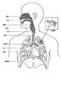
1.2.1 ヒト呼吸器系とその疾患
身体の呼吸器系はガス交換を促進する。鼻と口が患者の気道の入口を形成する。1.2 (2) Description of related art 1.2.1 Human respiratory system and its diseases The respiratory system of the body promotes gas exchange. The nose and mouth form the entrance to the patient's airway.
気道は一連の枝管を含み、それらは肺に深く入るにつれて狭く、短くそしておびただしくなる。肺の主要機能はガス交換であり、酸素は空気から静脈血に入り、二酸化炭素が運び出される。気管は左右の主気管支に分かれ、さらに分岐して最後に終末細気管支となる。気管支は誘導気道を構成し、ガス交換には関与しない。気道をさらに分割すると呼吸細気管支となり、最終的に肺胞となる。ガス交換が行われる肺の胞状の領域は、呼吸領域と呼ばれる。John B. West著「呼吸生理学」Lippincott Williams & Wilkins、第9版、2011年発行を参照。 The airway includes a series of branches that become narrower, shorter, and messy as you go deeper into the lungs. The main function of the lung is gas exchange, oxygen enters the venous blood from the air and carbon dioxide is carried out. The trachea is divided into left and right main bronchus, and further branches to become terminal bronchioles. The bronchi constitute the guiding airway and are not involved in gas exchange. When the airway is further divided, it becomes respiratory bronchioles and eventually becomes alveoli. The pulmonary alveolar region where gas exchange takes place is called the respiratory region. John B. See “Respiratory Physiology” by West, Lippincott Williams & Wilkins, 9th edition, 2011.
一連の呼吸器疾患が存在する。呼吸器疾患のいくつかの例には閉塞性睡眠時無呼吸(OSA)、チェーン・ストークス呼吸(CSR)、肥満過呼吸症候群(OHS)、慢性閉塞性肺疾患(COPD)、神経筋疾患(NMD)または胸壁疾患が含まれる。 There is a range of respiratory diseases. Some examples of respiratory diseases include obstructive sleep apnea (OSA), Chain Stokes breathing (CSR), obesity hyperpnea syndrome (OHS), chronic obstructive pulmonary disease (COPD), neuromuscular disease (NMD) ) Or chest wall disease.
別の面では、健常な個人はシステムと装置の利点を生かして、呼吸疾患の発症を防止することができる。 In another aspect, healthy individuals can take advantage of the system and device to prevent the development of respiratory disease.
1.2.2 治療
鼻持続的気道陽圧(CPAP)療法は、閉塞性睡眠時無呼吸(OSA)の治療に用いられてきた。この仮説は、持続的気道陽圧が空気的副子として作用し、軟口蓋と舌を前方に押して、後口咽頭壁から離せば、上気道の閉塞を防止できると言うものである。1.2.2 Treatment Nasal continuous positive airway pressure (CPAP) therapy has been used to treat obstructive sleep apnea (OSA). The hypothesis is that continuous positive airway pressure acts as an air splint, pushing the soft palate and tongue forward and away from the posterior oropharyngeal wall to prevent obstruction of the upper airway.
非侵襲的換気(NIV)は、患者が十分に呼吸しおよび/または適切な酸素レベルを体内に維持するのを支援するために、呼吸作業の一部またはすべてを行って、上気道を通して患者に換気補助を提供する。換気補助は患者インタフェースを経由して提供される。NIVはCSR,OHS,COPD,MDおよび胸壁疾患の治療に使用されてきた。 Noninvasive ventilation (NIV) performs some or all of the breathing work to help the patient breathe well and / or maintain an adequate oxygen level in the body and to the patient through the upper airway. Provide ventilation assistance. Ventilation assistance is provided via the patient interface. NIV has been used to treat CSR, OHS, COPD, MD and chest wall disease.
侵襲的換気(IV)は、もはや自分で効果的に呼吸できない患者に換気補助を提供し、気管切開チューブを使用して提供される。 Invasive ventilation (IV) provides ventilatory assistance to patients who can no longer effectively breathe themselves and is provided using a tracheostomy tube.
人工呼吸器は、患者に供給される呼吸のタイミングと圧力を制御でき、患者が行う呼吸をモニターできる。患者を制御しモニターする方法は、典型的には従量式と圧力サイクル式方法を含む。従量方法はとりわけ、圧力調整容量制御(PRVC)、容量換気(VV)と容量制御連続強制換気(VC−CMV)技術を含む。圧力サイクル式はとりわけ支援制御(AC)、同期間欠強制換気(SIMV)、調節機械換気(CMV)、圧力補助換気(PSV)、持続的陽圧呼吸(CPAP)または呼吸終末陽圧技術(PEEP)を含む。 The ventilator can control the timing and pressure of breathing delivered to the patient and monitor the breathing performed by the patient. Methods for controlling and monitoring a patient typically include metered and pressure cycle methods. Metered methods include, among other things, pressure regulation volume control (PRVC), volume ventilation (VV) and volume controlled continuous forced ventilation (VC-CMV) techniques. Pressure cycle formulas are Assisted Control (AC), Synchronous Intermittent Forced Ventilation (SIMV), Controlled Mechanical Ventilation (CMV), Pressure Assisted Ventilation (PSV), Continuous Positive Pressure Breathing (CPAP) or Positive End-breath Pressure Technology (PEEP) including.
1.2.3 システム
治療システムは、呼吸圧力治療装置(RPT装置)、空気回路、加湿器、患者インタフェースおよびデータ管理を含む。1.2.3 System The therapy system includes a respiratory pressure therapy device (RPT device), an air circuit, a humidifier, a patient interface and data management.
1.2.4 患者インタフェース
患者インタフェースは、例えば呼吸できるガスの流れを提供することによって、呼吸装置をそのユーザーに接続するのに使用できる。呼吸できるガスの流れは、鼻および/または口へのマスク、口へのチューブまたは患者の気管への気管開口チューブを経由して提供される。適用する治療法次第で、患者インタフェースは、例えば患者の顔の部分とでシールを形成してもよく、治療が効果をもたらすように周囲圧力と十分に相違した圧力で、例えば周囲圧力に対して約10cmH2Oの陽圧で、ガスを送出する。酸素の送出のようなほかの治療の形態では、約10cmH2Oの陽圧でのガスの気道への供給を容易にするのに十分なシールを患者インタフェースに含めなくてもよい。1.2.4 Patient Interface The patient interface can be used to connect a breathing device to its user, for example by providing a breathable gas flow. Breathable gas flow is provided via a mask to the nose and / or mouth, a tube to the mouth or a tracheostomy tube to the patient's trachea. Depending on the treatment method applied, the patient interface may form a seal with, for example, a portion of the patient's face, at a pressure sufficiently different from ambient pressure so that the treatment is effective, for example with respect to ambient pressure The gas is delivered at a positive pressure of about 10 cmH2 O. In other form of treatment, such as oxygen delivery may not include enough seal to the patient interface to facilitate the supply of about 10 cm H 2O of the gas at positive pressure airway.
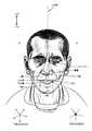
患者インタフェースのデザインにはいろいろな難問がある。顔面は複雑な3次元の形状をしている。鼻の大きさと形は個人間でかなり異なる。頭部には骨、軟骨と軟組織があり、顔面の異なる領域は機械的な力に対して異なる反応をする。顎または下顎は頭蓋のほかの骨に関連して動くことがある。頭全体が呼吸治療の間に動くことがある。 There are various challenges in designing patient interfaces. The face has a complex three-dimensional shape. The size and shape of the nose varies considerably among individuals. The head has bones, cartilage and soft tissue, and different areas of the face react differently to mechanical forces. The jaw or mandible may move relative to other bones of the skull. The entire head may move during breathing therapy.
これらの難問のために、マスクによっては、ひどく目立つ、審美的に好ましくない、コストが高い、装着が不十分である、使用困難である、及び、特に長期間の着用または患者がシステムに不慣れの場合に不快である、のうちの1つまたはそれ以上の問題に悩まされる。例えば、飛行士専用にデザインされたマスク、個人の保護装置の一部としてデザインされたマスク(例えば、フィルターマスク)、SCUBAマスク、または麻酔薬投与のためのマスクは、本来の適用には耐えるが、長期間、例えば数時間着用するのは好ましくないほど不愉快である。睡眠中にマスクを着用しなければならない場合は特にそうである。 Because of these challenges, some masks are highly noticeable, aesthetically unfavorable, expensive, poorly worn, difficult to use, and especially worn for extended periods of time or patients unaccustomed to the system. One or more of the problems that are uncomfortable in the case are bothered. For example, masks designed specifically for aviators, masks designed as part of personal protective equipment (eg, filter masks), SCUBA masks, or masks for anesthetic administration may withstand original applications. It is unpleasantly unpleasant to wear for a long time, for example several hours. This is especially true when a mask must be worn while sleeping.
患者が治療に従う限り、鼻CPAP治療はある呼吸器疾患の治療に特に効果的である。マスクが不愉快であるか使用困難であれば、患者は治療に従わないかもしれない。患者は自分のマスクを定期的に洗浄するようしばしば推奨されているので、マスクの洗浄が困難であれば(例えば、組立または分解が困難)、患者は自分のマスクを洗浄しないかもしれず、これは患者のコンプライアンスに影響を与える。 As long as the patient follows treatment, nasal CPAP treatment is particularly effective in treating certain respiratory diseases. If the mask is unpleasant or difficult to use, the patient may not follow treatment. Patients are often encouraged to clean their masks regularly, so if the mask is difficult to clean (eg difficult to assemble or disassemble), the patient may not clean his mask, Affect patient compliance.
その他の適用(例えば、飛行士)のためのマスクを睡眠呼吸障害に使用するのは適切でないかもしれないが、睡眠呼吸障害に使用するようデザインされたマスクはその他の適用に適しているかもしれない。 While masks for other applications (eg, aviators) may not be appropriate for use in sleep disordered breathing, masks designed for use in sleep disordered breathing may be suitable for other applications Absent.
これらの理由により、睡眠中の鼻CPAPの送出のための患者インタフェースは独特な分野である。 For these reasons, patient interfaces for the delivery of nasal CPAP during sleep are a unique area.
1.2.4.1 シール形成部
患者インタフェースはシール形成部を含む。これは患者の顔面と直接接触するので、シール形成部の形状と形態は患者インタフェースの有効性と快適さに直接影響を与えることがある。1.2.4.1 Seal formation The patient interface includes a seal formation. Since this is in direct contact with the patient's face, the shape and form of the seal formation may directly affect the effectiveness and comfort of the patient interface.
患者インタフェースは、シール形成部分が使用中の顔面の何処と当たるかのデザイン意図によって、一部特徴付けられる。患者インタフェースの1つの形態において、シール形成部は左と右のそれぞれの鼻孔に当たる2つの準部分を持つことができる。患者インタフェースの一形態において、シール形成部分は使用中に両方の鼻孔を囲む単一のエレメントであってよい。このような単一のエレメントは、例えば顔面の上唇領域と鼻梁領域を覆うようにデザインしてよい。患者インタフェースの一形態において、シール形成部分は例えば顔面の下唇領域上にシールを形成するなど、使用中の口の領域を囲むエレメントで成ってよい。患者インタフェースの一形態において、シール形成部分は使用中の両方の鼻孔と口の部分を囲む単一のエレメントで成ってよい。患者インタフェースのこれらの異なるタイプは、それらの製造者が付けた種々の名称で知られており、鼻マスク、顔全体マスク、鼻枕、鼻噴霧および口−鼻マスクが含まれる。 The patient interface is characterized in part by the design intent of where the seal-forming part hits the face in use. In one form of patient interface, the seal former can have two sub-portions that hit the left and right nostrils. In one form of patient interface, the seal-forming portion may be a single element that surrounds both nostrils during use. Such a single element may be designed to cover, for example, the upper lip region and the nasal bridge region of the face. In one form of the patient interface, the seal-forming portion may consist of an element surrounding the area of the mouth that is in use, such as forming a seal on the lower lip area of the face. In one form of patient interface, the seal-forming portion may consist of a single element that surrounds both the nostril and mouth portions in use. These different types of patient interfaces are known by various names given by their manufacturers and include nasal masks, whole face masks, nasal pillows, nasal sprays and mouth-nose masks.
患者の顔の一領域での効果的なシール形成部分は、患者の顔の形状、構造、ばらつきおよび敏感な部分が異なるので、別の領域には適していないことがある。例えば、患者の額を覆う水中メガネのシールを患者の鼻に使用するには適当でない。 An effective seal-forming part in one area of the patient's face may not be suitable for another area because the patient's face shape, structure, variation and sensitive parts are different. For example, a seal of underwater glasses that covers the patient's forehead is not suitable for use on the patient's nose.
1つのデザインがさまざまな異なる顔の形状および大きさに適し、快適で効果的であるのように、或るシール形成部を大量生産用にデザインすることができる。患者の顔の形状と大量生産された患者のインタフェースのシール形成部の間で不整合ができるまで、1つまたは両方を適合させてシールを形成しなければならない。 Certain seal formations can be designed for mass production so that one design is suitable for a variety of different facial shapes and sizes and is comfortable and effective. One or both must be fitted to form a seal until there is a mismatch between the shape of the patient's face and the seal-forming portion of the mass-produced patient interface.
シール形成部分の1つのタイプは、患者インタフェースの周辺付近に伸び、シール形成部分が患者の顔に係合しようとしており、力が患者インタフェースに加えられた時に患者の顔に抗してシールするように意図される。シール形成部分は、空気または液体で充満されたクッション、またはゴムのようなエラストマーでできた弾力性のあるシールエレメントの成形または形成面を含むことができる。このタイプのシール形成では、適合が適切でなければ、シール形成部分と顔の間にギャップがあり、シールを形成するために顔に抗して患者インタフェースに追加の力を加える必要がある。 One type of seal-forming portion extends near the periphery of the patient interface so that the seal-forming portion is about to engage the patient's face and seals against the patient's face when a force is applied to the patient interface. Intended for. The seal-forming part can include a molded or formed surface of a resilient seal element made of a cushion filled with air or liquid, or an elastomer such as rubber. With this type of seal formation, if the fit is not appropriate, there is a gap between the seal formation portion and the face, and additional force must be applied to the patient interface against the face to form the seal.
シール形成部のもう1つのタイプは、マスクの周辺近辺に位置した薄い材料でできたフラップシールを含み、マスク内に陽圧がかかると患者の顔に抗してセルフシーリングを行う。シール形成部分の以前のタイプのように、顔面とマスクとの間の適合が良好でないと、シールを形成するのに追加の力が必要になるかまたはマスクから漏れが生じる。さらに、シール形成部分の形状が患者のそれに適合しない場合、使用中にしわが生じたり曲がったりすることがあり、漏れが発生する。 Another type of seal-forming part includes a flap seal made of a thin material located near the periphery of the mask, which performs self-sealing against the patient's face when positive pressure is applied within the mask. If the fit between the face and the mask is not as good as the previous type of seal-forming part, additional force is required to form the seal or leakage from the mask. In addition, if the shape of the seal-forming part does not match that of the patient, it may wrinkle or bend during use, resulting in leakage.
シール形成部分のもう1つのタイプは、例えば鼻孔への挿入のような摺合せエレメントを含むことができる。 Another type of seal-forming portion can include a sliding element, such as insertion into a nostril.
シール形成部分のもう1つの形態は、接着剤を使ってシールを達成する。顔面に接着剤を絶えず適用しこれを除去するのが不便と感じる患者もいる。 Another form of seal-forming portion uses an adhesive to achieve the seal. Some patients find it inconvenient to constantly apply and remove the adhesive on the face.
ResMed Limitedに譲渡された下記の特許出願に、さまざまな患者インタフェース・シール形成部の技術が開示されている:WO1998/004,310、WO2006/074,513、WO2010/135,785。 Various patient interface seal forming techniques are disclosed in the following patent applications assigned to ResMed Limited: WO 1998/004, 310, WO 2006 / 074,513, WO 2010 / 135,785.
鼻枕の一形態がPuritan Bennettが製造するAdam Circuitに見出される。もう1つの鼻枕または鼻噴霧はPuritan−Bennett Corporationに譲渡された米国特4,782,832(Trimbleほか)の題目である。 One form of nasal pillow is found in Adam Circuit manufactured by Puritan Bennett. Another nasal pillow or nasal spray is the subject of US Pat. No. 4,782,832 (Trimble et al.) Assigned to Puritan-Bennett Corporation.
ResMed Limitedは、鼻枕を組み込んだ以下の製品を製造した:SWIFT鼻枕マスク、SWIFTII鼻枕マスク、SWIFT LT鼻枕マスク、SWIFT FX鼻枕マスクおよびLIBERTYフルフェース・マスク。RedMedに譲渡された以下の特許出願に、鼻枕マスクが記述されている。国際特許出願WO2004/073,778(とりわけRedMed SWIFT鼻枕の特徴を記載)、米国特許出願2009/0044808(とりわけRedMed SWIFT LT鼻枕の特徴を記載)、国際特許出願WO2005/063,328とWO2006/130,903(とりわけResMed LIBERTYフルフェース・マスクの特徴を記載)、国際特許出願WO2009/052,560(とりわけResMed SWIFT FX鼻枕の特徴を記載)。 ResMed Limited manufactured the following products incorporating nasal pillows: SWIFT nasal pillow mask, SWIFT II nasal pillow mask, SWIFT LT nasal pillow mask, SWIFT FX nasal pillow mask and LIBERTY full face mask. The following patent application assigned to RedMed describes a nasal pillow mask. International patent application WO2004 / 073,778 (especially describing features of RedMed SWIFT nasal pillow), US patent application 2009/0044808 (especially describing features of RedMed SWIFT LT nasal pillow), international patent applications WO2005 / 063,328 and WO2006 / 130,903 (especially describing the features of the ResMed LIBERTY full face mask), international patent application WO2009 / 052,560 (especially describing the features of the ResMed SWIFT FX nasal pillow).
1.2.4.2 位置決めと安定化
陽圧空気治療に使用する患者インタフェースのシール形成部は、シールを崩壊しようとする空気圧の対応する力の影響を受ける。このようにシール形成部を位置決めし、それを顔の適当な位置とシーリングの関係を維持するために様々な技術が使用されてきた。1.2.4.2 Positioning and Stabilization The patient interface seal formation used for positive pressure air therapy is subject to the corresponding forces of air pressure trying to collapse the seal. Various techniques have been used to position the seal formation in this way and maintain it in the proper face and sealing relationship.
1つの技術に接着剤の使用がある。例えば米国特許公開US2010/0000534を参照。 One technique involves the use of adhesives. See for example US Patent Publication US2010 / 0000534.
もう1つの技術として、1つまたはそれ以上のひもと安定化装着帯の使用がある。このような装着帯の多くは、1つまたはそれ以上の不適合、かさばる、不快および使用がぎこちない、の問題に悩まされる。 Another technique is the use of one or more straps and stabilizing straps. Many of these wearing bands suffer from the problem of one or more nonconformities, bulky, discomfort and awkward use.
1.2.5呼吸圧力治療(RPT)装置
睡眠呼吸障害の治療に用いられる1つの既知のRPTは、ResMedが製造するS9 Sleep Therapy Systemである。もう1つのRPT装置の実施例は人工呼吸器である。成人および小児用人工呼吸器のResMed StellarTMシリーズのような人工呼吸器は、NMD、OHSおよびCOPD(ただしこれらに限定されない)のような多くの疾患を治療しているさまざまな患者のために侵襲および非侵襲非依存人工呼吸器のサポートを提供できる。RPT装置は流れ発生器としても知られている。1.2.5 Respiratory Pressure Therapy (RPT) Device One known RPT used to treat sleep breathing disorders is the S9 Sleep Therapy System manufactured by ResMed. Another RPT device embodiment is a ventilator. Ventilators such as the ResMed Stellar™ series of adult and pediatric ventilators are invasive for a variety of patients treating many diseases such as, but not limited to, NMD, OHS and COPD And non-invasive non-dependent ventilator support can be provided. The RPT device is also known as a flow generator.
ResMed Elisee(商標)150人工呼吸器とResMed VS III(商標)人工呼吸器は、成人および小児患者の多数の疾患の治療に適した侵襲および非侵襲依存人工呼吸器を提供することができる。これらの人工呼吸器は、単一または二重肢回路の付いた容積式換気モードと気圧式換気モードを提供する。 The ResMed Elisee ™ 150 and ResMed VS III ™ ventilators can provide invasive and non-invasive dependent ventilators suitable for the treatment of numerous diseases in adult and pediatric patients. These ventilators offer positive and negative ventilation modes with single or double limb circuits.
RPT装置は、典型的にはモーター駆動の送風機または圧縮ガスリザーバのような圧力発生器から成り、患者の気道に空気の流れを供給するように構成される。場合によっては、空気流を陽圧で患者の気道に供給することができる。RPT装置の出口は、空気回路を経由して上記の患者のインタフェースに接続される。 RPT devices typically consist of a pressure generator such as a motor driven blower or a compressed gas reservoir and are configured to provide a flow of air to the patient's airway. In some cases, airflow can be delivered to the patient's airways with positive pressure. The outlet of the RPT device is connected to the patient interface via an air circuit.
RPT装置は典型的には入口フィルター、いろいろなセンサーおよびマイクロプロセッサーをベースにしたコントローラーも含む。送風機はサーボ制御のモーター、ボリュートおよびインペラーを含む。場合によってはモーターのためのブレーキを組み込んで、モーターとインペラーの慣性に打ち勝って送風機の速度をより速やかに減速できる。ブレーキングによって送風機が低圧状態をより速やかに時間内に達成して、慣性にもかかわらず呼気との同期を行う。場合によっては圧力発生器は、モーター速度の制御の代替として、患者に吐出される圧力を変更する手段として発生した空気を大気へ吐出できるバルブを含むことができる。センサーはとりわけモーター速度、質量流量および圧力変換器などによる出口圧力を測定する。コントローラーは統合データ検索および表示機能の付いたまたは付いていないデータ記憶容量を含むことができる。 RPT devices typically also include an inlet filter, various sensors and a microprocessor-based controller. The blower includes a servo-controlled motor, volute and impeller. In some cases, a brake for the motor can be incorporated to overcome the inertia of the motor and impeller and reduce the speed of the blower more quickly. By braking, the blower achieves the low pressure state more quickly in time and synchronizes with exhalation despite inertia. In some cases, the pressure generator can include a valve that can discharge the generated air to the atmosphere as a means of changing the pressure delivered to the patient as an alternative to controlling the motor speed. The sensor measures, among other things, motor speed, mass flow and outlet pressure, such as by a pressure transducer. The controller can include data storage capacity with or without integrated data retrieval and display functions.

1.2.6 加湿器
加湿なしに呼吸できるガスの流れを送出すると、気道が乾燥することがある。医療用加湿器は、呼吸できるガスの流れの湿度および/または温度を周囲空気に対して、要求があれば、典型的には患者が睡眠中または休息中に(例えば病院において)上げるのに使用される。その結果、医療用加湿器は好ましくはベッドの横に置くように小さくてよく、患者の周囲を加湿および/または加熱しないで、患者に送出された呼吸できるガスの流れだけを加湿および/または加熱するように構成できる。例えば、部屋をベースにしたシステム(例えば、サウナ、空調装置、蒸発冷却器)も患者が呼吸する空気を加湿できるが、これらのシステムは部屋全体を加湿および/または加熱することになり、居住者に不快をもたらすことがある。1.2.6 Humidifier Delivering a flow of gas that can be breathed without humidification may dry the airways. Medical humidifiers are typically used to raise the humidity and / or temperature of a breathable gas stream relative to ambient air, if required, typically during patient sleep or rest (eg in a hospital) Is done. As a result, the medical humidifier may preferably be small to be placed next to the bed, humidifying and / or heating only the flow of breathable gas delivered to the patient without humidifying and / or heating the patient's surroundings. Can be configured to For example, room-based systems (eg, saunas, air conditioners, evaporative coolers) can humidify the air that the patient breathes, but these systems humidify and / or heat the entire room and May cause discomfort.
流れ発生器またはRPT装置および患者インタフェースと共に加湿器を使用すると、加湿されたガスが生成され、これが鼻粘膜の乾燥を最小限に抑え、患者の気道の快適さを増す。加えて、涼しい気候では、暖かい空気がインタフェースの中の患者の顔およびその周りに広く当たると、冷たい空気よりずっと快適である。 The use of a humidifier with a flow generator or RPT device and patient interface generates humidified gas that minimizes drying of the nasal mucosa and increases patient airway comfort. In addition, in a cool climate, warm air is much more comfortable than cold air when it hits the patient's face in and around the interface widely.
いろいろな形態の呼吸用加湿器があり、空気回路を経て呼吸装置に連結された自立型は関連の呼吸装置に組込まれるかまたは連結されるように構成されるものがある。既知の受動的な加湿器はある安堵を提供できるが、一般に加熱加湿器は患者が快適であるように十分な湿度と温度を提供する。加湿器は典型的には数百ミリリットル(ml)の容量を有する水リザーバーまたはタブ型容器、リザーバーの中の水を加熱する加熱エレメント、加湿のレベルを変更できる制御装置、流れ発生器またはRPT装置からのガスを受け入れるガス入口および加湿されたガスを患者インタフェースへ吐出する空気回路に接続できるように適合されたガス出口を含む。 There are various forms of respirator humidifiers, some of which are self-contained connected to the respirator via an air circuit or are configured to be incorporated into or connected to an associated respirator. While known passive humidifiers can provide some relief, heated humidifiers generally provide sufficient humidity and temperature to make the patient comfortable. A humidifier is typically a water reservoir or tub container with a capacity of several hundred milliliters (ml), a heating element that heats the water in the reservoir, a control device that can change the level of humidification, a flow generator or an RPT device And a gas outlet adapted to be connected to an air circuit for delivering humidified gas to the patient interface.
加熱したパスオーバー加湿は、RPT装置で使用される加湿の形態の一般的な形態である。このような加湿器において加熱エレメントは、水タブの下にあって水タブと熱的接触にあるヒータープレートに組み込むことができる。このように熱は主として伝導によってヒータープレートから水リザーバーに伝えられる。RPT装置からの空気の流れは水タブの中の加熱された水を通り、その結果水蒸気が空気の流れに持ち去られる。ResMed H4i(商標)とH5i(商標)加湿器はこのような加熱パスオーバー加湿器の例であり、それぞれRsdMed S8およびS9 CPAP装置と組み合わせて使用する。 Heated passover humidification is a common form of humidification used in RPT equipment. In such a humidifier, the heating element can be incorporated into a heater plate under the water tab and in thermal contact with the water tab. Thus, heat is transferred from the heater plate to the water reservoir primarily by conduction. The air flow from the RPT device passes through heated water in the water tub so that water vapor is carried away into the air flow. ResMed H4i ™ and H5i ™ humidifiers are examples of such heated passover humidifiers, which are used in combination with RsdMed S8 and S9 CPAP devices, respectively.
その他の加湿器、例えば泡または拡散加湿器、ジェット加湿器またはウイッキング加湿器も使用される。泡または拡散加湿器において、空気は水表面の下を通り表面に泡となって現れる。ジェット加湿器は水のエアロゾルを生成し、加湿器を出る前に粒子が除去されるかまたは蒸発するようにバッフルまたはフィルターを使用する。ウイッキング加湿器はスポンジまたは紙のような水を吸収する材料を使用し、毛細管現象によって水を吸収する。吸収材料の中の蒸発が空気流に持ち去られるように、水吸収材料は空気流路の中または少なくともその一部に隣接させて置く。 Other humidifiers are also used, such as foam or diffusion humidifiers, jet humidifiers or wicking humidifiers. In a foam or diffusion humidifier, air appears below the surface of the water as bubbles on the surface. A jet humidifier produces an aerosol of water and uses a baffle or filter so that particles are removed or evaporated before exiting the humidifier. Wicking humidifiers use water-absorbing materials such as sponges or paper and absorb water by capillary action. The water absorbing material is placed in or adjacent to at least a portion of the air flow path so that evaporation in the absorbing material is carried away by the air stream.
加湿の代替の形態は、ResMed HumiCare(商標)D900加湿器によって提供される。この加湿器はCounterStream(商標)技術を使用して空気流を第1の方向の大きい表面に向け、一方加熱された水を第2の方向の大きい表面積に供給する。ResMed HumiCare(商標)D900は、さまざまな侵襲または非侵襲の人工呼吸器で使用できる。 An alternative form of humidification is provided by the ResMed HumiCare ™ D900 humidifier. The humidifier uses CounterStream ™ technology to direct an air stream to a large surface in a first direction while supplying heated water to a large surface area in a second direction. ResMed HumiCare ™ D900 can be used with a variety of invasive or non-invasive ventilators.
本開示の態様は、患者装置をネットワーク経由で更新する、コンピュータにより実施される方法を提供する。この方法は複数の患者装置に関連したコンフィギュレーション・データ(構成データ)にアクセスすることを含むことができ、ここに前記複数の患者装置のそれぞれは命令のセットを実装する。この方法は、また、前記複数の患者装置から、1つまたはそれ以上の基準を満たすコンフィギュレーション・データを有する1つまたはそれ以上の患者装置を識別することと、2つ以上の更新が提供される場合に、前記コンフィギュレーション・データが、命令更新が前記1つまたはそれ以上の患者装置に現在インストールされていないことを示す前記1つまたはそれ以上の患者装置に提供すべき前記命令更新を選択することと、を含む。この方法は、また、前記1つまたはそれ以上の患者装置に前記命令更新を送信することと、前記1つまたはそれ以上の患者装置のそれぞれが首尾よく前記命令更新をインストールしたかどうかを決定することと、を含む。さらに、前記コンフィギュレーション・データは、前記命令更新を首尾よくインストールした前記1つまたはそれ以上の患者装置のそれぞれに対して更新されることができる。 Aspects of the present disclosure provide a computer-implemented method for updating patient devices over a network. The method can include accessing configuration data (configuration data) associated with a plurality of patient devices, wherein each of the plurality of patient devices implements a set of instructions. The method also provides identifying one or more patient devices having configuration data that meets one or more criteria from the plurality of patient devices and two or more updates. The configuration data selects the instruction update to be provided to the one or more patient devices indicating that the instruction update is not currently installed on the one or more patient devices. And including. The method also determines sending the command update to the one or more patient devices and whether each of the one or more patient devices has successfully installed the command update. Including. Further, the configuration data may be updated for each of the one or more patient devices that have successfully installed the instruction update.
もう1つの態様において、前記命令更新は下記の少なくとも1つを含むことができる:命令更新ファイルの場所を指定するデータ;装置のどのコンポーネントに前記更新を適用すべきかについての指示;各装置に前記更新を実施するスケジュール時間;前記更新が適用されるべきとの確認を要求すべきかどうかの指示;該当する場合、患者の治療が停止されるまで前記更新を適用しないとの指示;まだ発生していない更新のキャンセルを可能にするデータ構造と機能性;単一操作において大量の更新を要求するバッチ能力;および、前記更新のステータスを示す単一操作においてこれらの更新のステータスをチェックする能力。 In another aspect, the instruction update can include at least one of the following: data specifying the location of an instruction update file; instructions on which component of the device the update should apply; Scheduled time to perform the update; an indication of whether confirmation should be applied that the update should be applied; if applicable, an indication not to apply the update until patient treatment is stopped; Data structures and functionality that allow cancellation of no updates; batch ability to request a large number of updates in a single operation;
前記1つまたはそれ以上の基準と命令更新を選択することは、遠隔計算装置(遠隔コンピューティングデバイス)、例えば臨床医またはサービス員のコンピュータ、から受信した1つまたはそれ以上の送信に基づくことができる。さらに命令更新を選択するステップは、遠隔計算装置のユーザーからの受信入力に基づくことができ、該受信入力は、複数の命令更新からの前記命令更新を示す。前記命令更新を送信することは、検証データを送信することをさらに含み、ここに、検証データは、患者装置が使用して、該受信した命令更新が完了したことを検証する。この場合、前記更新が“完了した”との表現は、前記更新が決して破損または変更されていないことを示すことも意味している。前記命令更新は、前記命令更新が首尾よくインストールされなかったと決定された各装置に再送信されることができる。 Selecting the one or more criteria and instruction update may be based on one or more transmissions received from a remote computing device (remote computing device), eg, a clinician or service personnel computer. it can. Further, the step of selecting an instruction update may be based on a received input from a user of the remote computing device, the received input indicating the instruction update from a plurality of instruction updates. Sending the command update further includes sending verification data, where the verification data is used by the patient device to verify that the received command update is complete. In this case, the expression “completed” also means that the update has never been corrupted or altered. The command update may be retransmitted to each device that has been determined that the command update was not successfully installed.
さらにもう1つの態様によれば、前記1つまたはそれ以上の患者装置のそれぞれからの指し示しは、前記命令セットが首尾よくインストールされたことを示し、計算装置にメッセージが送信され、ここに、このメッセージは、前記1つまたはそれ以上の患者装置に対する前記命令更新が首尾よくインストールされたことを特定する。前記コンフィギュレーション・データは、少なくとも次のうちの1つを含む:a)通し番号、b)前記患者装置に現在インストールされている命令のセットのバージョン、c)ハードウエアのバージョン、d)前記患者装置が使用されている領域、およびe)前記患者装置に以前に首尾よく適用された、または、されなかった前記命令更新の記録。 According to yet another aspect, an indication from each of the one or more patient devices indicates that the instruction set has been successfully installed and a message is sent to the computing device, where The message identifies that the command update for the one or more patient devices has been successfully installed. The configuration data includes at least one of the following: a) a serial number, b) a version of a set of instructions currently installed on the patient device, c) a hardware version, d) the patient device. And e) a record of the command updates that have been or have not been successfully applied to the patient device previously.
さらにもう1つの態様によれば、前記複数の患者装置は、呼吸圧力治療装置であることができる。前記コンフィギュレーション・データは次のうちの少なくとも1つを含むことができる:a)通し番号、b)前記患者装置に現在インストールされている命令のセットのバージョン、c)ハードウエアのバージョン。加えて、前記命令更新は、第1の部分および第2の部分を含み、ここで、前記患者装置の第1のコンポーネントは、前記命令更新の前記第1の部分に従って動作し、第2のコンポーネントは、前記命令更新の前記第2の部分に従って動作する。 According to yet another aspect, the plurality of patient devices can be respiratory pressure therapy devices. The configuration data may include at least one of the following: a) a serial number, b) a version of a set of instructions currently installed on the patient device, c) a hardware version. In addition, the command update includes a first portion and a second portion, wherein a first component of the patient device operates according to the first portion of the command update and a second component Operates according to the second part of the instruction update.
もう1つの態様において、医療を提供する装置を更新する方法は、患者装置の操作について第1の命令セットにアクセスすることと、該第1の命令セットにしたがって第1の操作セットを実施することと、遠隔計算装置からネットワークを通して更新データを受信することと、該更新データにそたがって前記第1の命令セットを更新して、更新された命令セットを生成することと、前記第1の命令セットの更新が行われたことの確認を前記遠隔計算装置に送信することと、該更新された命令セットにしたがって第2の操作セットを実施することと、を含むことができる。 In another aspect, a method for updating a device that provides medical care accesses a first instruction set for operation of a patient device and implements the first operation set according to the first instruction set. Receiving update data from a remote computing device over a network, updating the first instruction set in accordance with the update data to generate an updated instruction set, and the first instruction Sending a confirmation that a set update has occurred to the remote computing device and performing a second set of operations according to the updated instruction set.
この方法は、検証データを受信することを含み、該受信した更新データが完全なものかどうかを決定することをさらに含む。該受信した更新データが不完全と決定されると、前記患者装置は、エラー通知を前記遠隔計算装置に送信し、更新データの第2の送信を受信することができる。 The method includes receiving verification data, and further includes determining whether the received update data is complete. If it is determined that the received update data is incomplete, the patient device can send an error notification to the remote computing device and receive a second transmission of update data.
本技術は制限ではなく、実施例によって説明され、添付の図面における数字において同じ参照番号は同じエレメントを参照する。 The technology is illustrated by way of example and not limitation, and like reference numerals refer to like elements in the figures of the accompanying drawings.
本技術をさらに詳細に説明する前に、本技術は本明細書に記載された変わることのある特定の実施例に限定されないことを理解されたい。またこの開示で使用されている専門用語は、本明細書中で議論される特定の実施例のみを記述するのが目的であり、限定する意図のないことを理解すべきである。 Before describing the present technology in further detail, it is to be understood that the present technology is not limited to the specific embodiments described herein that may vary. It should also be understood that the terminology used in this disclosure is intended to describe only the specific embodiments discussed herein and is not intended to be limiting.
4.1 治療システム
1つの形態において、本技術は呼吸疾患を治療する器具を含む。この器具は空気のような加圧された呼吸できるガスを、患者インタフェース3000に至る空気吐出チューブを経て患者1000に供給する流れ発生器または送風機を含む。4.1 Treatment System In one form, the technology includes a device for treating a respiratory disorder. The instrument includes a flow generator or blower that supplies pressurized breathable gas, such as air, to the
4.2 治療
1つの形態において、本技術は陽圧を患者1000の気道入口に適用するステップを含む呼吸疾患を治療する方法を含む。4.2 Treatment In one form, the technology includes a method of treating a respiratory disorder that includes applying positive pressure to the airway entrance of a
4.2.1 OSAのための鼻CPAP
1つの形態において、本技術は鼻持続的気道陽圧を患者に適用することによって閉塞性睡眠時無呼吸(OSA)を治療する方法を含む。4.2.1 Nasal CPAP for OSA
In one form, the technology includes a method of treating obstructive sleep apnea (OSA) by applying nasal continuous positive airway pressure to a patient.
4.3 患者インタフェース3000
本技術の一形態による非侵襲型患者インタフェース3000は以下の機能面を有する:シール形成構造3100、プレナムチャンバー3200、位置決めおよび安定化構造3300、ベント3400および空気回路4170へ接続するための接続ポート3600。いくつかの形態において、機能面は1つまたはそれ以上の物理的コンポーネントによって提供されてよい。いくつかの形態において、1つの物理的コンポーネントが1つまたはそれ以上の機能面を提供できる。使用中は、シール形成構造3100が気道入口を取り巻くように配置され空気を陽圧で気道に供給する。4.3
A
4.3.1 シール形成構造3100
本技術の一形態において、シール形成構造3100はシール形成面を提供し、さらにクッション機能を提供できる。4.3.1
In one form of the present technology, the
本技術によるシール形成構造3100はシリコンのような柔らかく、柔軟で弾力性のある材料で構築できる。 The
1つの形態において、シール形成構造3100はシーリングフランジおよび支持フランジを含む。好ましくはシーリングフランジは、厚さが例えば約0.25mmから約0.45mmの約1mm未満で、プレナムチャンバー3200の周辺3210の周りに伸びる比較的薄い部材を含む。支持フランジはシーリングフランジより相対的に厚くてよい。支持フランジはシーリングフランジとプレナムチャンバー3200の周縁エッジの間に配置され、少なくとも周辺3210の周りに伸びる。支持フランジは、ばね様エレメントであり、あるいはそれを含み、使用中にシーリングフランジが曲がるのを支援する。使用中は、シーリングフランジはプレナムチャンバー3200におけるシステム圧力に直ちに反応でき、その裏面に作用して顔としっかりしたシーリング係合をするよう促す。 In one form, the
1つの形態において、非侵襲患者インタフェース3000のシール形成部は一対の鼻噴霧または鼻枕を含み、それぞれの鼻噴霧または鼻枕は患者の鼻のそれぞれの鼻孔とシールを形成するように構築されかつ配置される。 In one form, the seal-forming portion of the
本技術の態様による鼻枕は、下記を含む;少なくともその一部が患者の鼻の下でシールを形成する切頭円錐;円錐の下面の柔軟な領域で円錐を脚に接続している脚。さらに本技術の鼻枕が接続される構造は、脚の基部に隣接した柔軟な領域を含む。柔軟な領域は一致して自在継手を作り、切頭円錐と鼻枕が接続されている構造の変位と角変位の両方に対応する。例えば切頭円錐は、脚が接続されている構造に向けて軸方向に変位できる。 A nasal pillow according to aspects of the present technology includes: a truncated cone at least a portion of which forms a seal under the patient's nose; a leg connecting the cone to the leg at a flexible region on the underside of the cone. Furthermore, the structure to which the nasal pillow of the present technology is connected includes a flexible region adjacent to the base of the leg. The flexible regions coincide to create a universal joint, which accommodates both displacement and angular displacement of the structure where the truncated cone and nasal pillow are connected. For example, the truncated cone can be displaced axially towards the structure to which the legs are connected.
1つの形態において、非侵襲患者インタフェース3000は使用中に患者の顔の唇領域(即ち上唇)上でシールを形成するシール形成部を含む。 In one form, the
1つの形態において、非侵襲患者インタフェース3000は使用中に患者の顔の顎の領域にシールを形成するシール形成部を含む。 In one form, the
4.3.2 プレナムチャンバー3200
好ましくはプレナムチャンバー3200は、使用中にシールが形成される領域における平均的なヒトの顔の表面輪郭を補完するように形作られた周辺3210を有する。使用中は、プレナムチャンバー3200の周縁エッジは顔の隣接する表面に接近して置かれる。顔との実際の接触はシール形成構造3100によって提供される。好ましくは、シール形成構造3100は使用中はプレナムチャンバー3200の周辺全域3210の周りに伸びる。4.3.2
Preferably, the
一形態において、プレナムチャンバー3200は患者の鼻孔を取り巻きおよび/またはこれと流体連通しており、ここではプレナムチャンバー3200は(例えば図1bに示すように)鼻マスクの一部である。もう1つの形態において、プレナムチャンバー3200は患者の鼻孔と口を取り巻きおよび/またはこれらと流体連通しており、ここではプレナムチャンバー3200は(例えば図1cに示すように)フルフェース・マスクの一部である。さらに別の形態では、プレナムチャンバー3200は患者の1つまたはそれ以上の鼻孔と係合しおよび/または流体連通しており、ここではプレナムチャンバー3200は(例えば図29に示すように)鼻枕の一部である。 In one form, the
4.3.3 位置決めと安定化構造3300
好ましくは、本技術の患者インタフェース3000のシール形成構造3100は、使用中は位置決めおよび安定化構造3300によってシーリング位置に保持される。4.3.3 Positioning and
Preferably, the
4.4 RPT装置4000
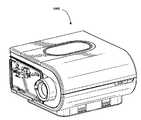
本技術の特徴を実装するのに適切な実施例のRPT装置4000は、機械的および空気的コンポーネント4100および電気的コンポーネント4200を含み、本明細書を通じて記述される1つまたはそれ以上の制御方法論またはアルゴリズムを実行するようプログラムできる。RPT装置は好ましくは外部ハウジング4010の上部4012と外部ハウジング4010の低部4014の2つに形成された外部ハウジング4010を有する。代替の形態では、外部ハウジング4010は1つまたはそれ以上のパネル(複数)4015を含む。好ましくはRPT装置4000は、RPT装置4000の1つまたはそれ以上の内部コンポーネントを支持するシャーシ4016を含む。1つの形態において、空気ブロック4020はシャーシ4016で支持されるかまたはその一部として形成される。RPT装置4000はハンドル4018を含むことができる。4.4
An
RPT装置4000の空気路は好ましくは入口空気フィルター4112、入口マフラー4122、陽圧の空気を供給できる(好ましくは送風機4142により)制御できる圧力装置4140および出口マフラー4124を含む。空気路には1つまたはそれ以上の圧力変換器4272および流れセンサー4274が含まれる。 The air path of the
好ましい空気ブロック4020は、外部ハウジング4010内に位置した空気路の一部を含む。 A
RPT装置4000は好ましくは電源4210、1つまたはそれ以上の入力装置4220、中央コントローラー4230、治療装置コントローラー4240および/または以前に記述された任意のコントローラー、圧力装置4140、1つまたはそれ以上の保護回路4250、変換器4270、データ通信インタフェース4280および1つまたはそれ以上の出力装置4290を有する。電気コンポーネント4200は単一のプリント回路基板アセンブリー(PCBA)4202上に実装される。代替の形態として、RPT装置4000は1つ以上のPCBA 4202を含むことができる。 The
1つまたはそれ以上のプロセッサーを含むことができるRPT装置4000の中央コントローラー4230は、1つまたはそれ以上のアルゴリズムのモジュールを実行するようにプログラムでき、好ましくは事前処理モジュール、治療エンジンモジュール、圧力制御モジュールおよびさらに好ましくは故障状態モジュールを含むことができる。該コントローラーは、本明細書を通じて記述される1つまたはそれ以上のベント制御方法論を組み込んだベント制御モジュールをさらに含むことができる。 The
4.4.1 RPT装置機械的および空気的コンポーネント4100
4.4.1.1 空気フィルター(複数)4110
本技術の一形態によるRPT装置は、空気フィルター4110または複数のフィルター4110を含むことができる。4.4.1 RPT machine mechanical and pneumatic component 4100
4.4.1.1 Air Filter (plural) 4110
An RPT device according to an aspect of the present technology may include an
1つの形態において、入口空気フィルター4112は空気送風機(ブロワー)4142の上流の空気路の先頭に位置している。図4bを参照。 In one form, the
1つの形態において、例えば抗菌フィルターのような出口空気フィルター4114は空気ブロック4020の出口と患者インタフェース3000の間に位置している。図4bを参照。 In one form, an outlet air filter 4114, such as an antibacterial filter, is located between the outlet of the
4.4.1.2 マフラー(複数)4120
本技術の一形態において、入口マフラー4122は送風機4142の上流の空気路に位置している。図4bを参照。4.4.1.2 Muffler (plural) 4120
In one form of the present technology, the inlet muffler 4122 is located in the air path upstream of the
本技術の一形態において、出口マフラー4124は送風機4142と患者インタフェース3000の間の空気路に位置している。図4bを参照。 In one form of the present technology, the outlet muffler 4124 is located in the air path between the
4.4.1.3 圧力装置4140
本技術の一形態において、陽圧の空気の流れを生成する圧力装置4140は制御可能な送風機4142である。例えば送風機は、ボリュートの中に収めた一つまたはそれ以上のインペラーを有するブラシレスDCモーター4144を含む。送風機は好ましくは、例えば約120リットル/分の陽圧の空気を、約4cmH2Oから約20cmH2Oの範囲またはそのほかの形態で約30cmH2Oまでの範囲で吐出できる。4.4.1.3
In one form of the present technology, the
圧力装置4140は、治療装置コントローラー4240の制御下にある。 The
4.4.1.4 変換器(複数)4270
本技術の一形態において、1つまたはそれ以上の変換器4270が圧力装置4140の上流に位置している。1つまたはそれ以上の変換器4270は空気路におけるそのポイントの空気の特性を測定するように構築されかつ配置される。4.4.1.4 Converter (s) 4270
In one form of the present technology, one or
本技術の一形態において、1つまたはそれ以上の変換器4270が圧力装置4140の下流および空気回路4170の上流に位置している。1つまたはそれ以上の変換器4270が、空気路中のそのポイントの空気の特性を測定するように構築されかつ配置される。 In one form of the present technology, one or
本技術の一形態において、1つまたはそれ以上の変換器4270を患者インタフェース3000の近位に置くことができる。 In one form of the present technology, one or
4.4.1.5 抗スピルバック弁
本技術の一形態において、抗スピルバック弁が加湿器5000と空気ブロック4020の間に位置している。この抗スピルバック弁は、水が加湿器5000から上流、例えばモーター4144、に流れるリスクを低減するよう構築されかつ配置される。4.4.1.5 Anti-spillback valve In one form of the present technology, an anti-spillback valve is located between the
4.4.1.6 空気回路4170
本技術の態様による空気回路4170は、空気または呼吸できるガスの流れが空気ブロック4020と患者インタフェース3000の間を流れるように構築されかつ配置される。4.4.1.6
The
4.4.1.7 酸素補給
本技術の一形態において、補充酸素4180が空気通路中の1つのポイントに吐出される。4.4.1.7 Oxygen Supply In one form of the present technology,
本技術の一形態において、酸素補給は空気ブロック4020の上流に吐出される。 In one form of the present technology, supplemental oxygen is discharged upstream of the
本技術の一形態において、酸素補給4180は空気回路4170に吐出される。 In one form of the present technology,
本技術の一形態において、酸素補給4180は患者インタフェース3000に吐出される。 In one form of the present technology,
4.4.2 RPT装置電気コンポーネント4200
4.4.2.1 電源4210
本技術の一形態において、電源4210はRPT装置4000の外部ハウジング4010の内部にある。本技術のもう1つの形態において、電源4210はRPT装置4000の外部ハウジング4010の外部にある。4.4.2 RPT device
4.4.2.1
In one form of the present technology, the
本技術の一形態において、電源4210はRPT装置4000にのみ電気を提供する。本技術のもう1つの形態において、電源4210はRPT装置4000と加湿器5000の両方に電気を提供する。本明細書を通じて記載されているようにベントの配置のために、電源はさらにオプションで電源を任意のアクチュエータ、コントローラーおよび/またはセンサーに提供する。 In one form of the present technology, the
4.4.2.2 入力装置4220
本技術の一形態において、RPT装置4000は作業者が装置と対話できるように、ボタン、スイッチまたはダイアルの形態の1つまたはそれ以上の入力装置4220を含む。これらはベント配置のようなRPT装置のコンポーネントの操作の設定を入力するために実装される。ボタン、スイッチまたはダイアルは物理的装置またはタッチスクリーンからアクセスできるソフトウエア装置であってよい。1つの形態において、ボタン、スイッチまたはダイアルは外部ハウジング4010に物理的に接続するかまたはもう1つの形態では、中央コントローラー4230と電気的接続にあるレシーバーとの無線通信であってよい。4.4.2.2
In one form of the present technology, the
1つの形態において、入力装置4220は、作業者が値および/またはメニューオプションを選択できるように構築されかつ配置される。 In one form, the
4.4.2.3 中央コントローラー4230
本技術の一形態において、中央コントローラー4230は、入力装置4220から入力信号(複数)を受信し、出力装置4290および/または治療装置コントローラー4240に出力信号(複数)を提供するように構成された専用の電子回路である。4.4.2.3
In one form of the present technology, the
一形態において、中央コントローラー4230は特定用途向け集積回路である。もう1つの形態において、中央コントローラー4230は個別の電子コンポーネントを含む。 In one form, the
本技術のもう1つの形態において、中央コントローラー4230はx86 INTELプロセッサーのようなRPT装置4000を制御するのに適したプロセッサーである。 In another form of the present technology, the
本技術のもう1つの形態によるRPT装置4000を制御するのに適した中央コントローラーのプロセッサーは、ARM HoldingsのARM Cortex−Mプロセッサーに基づくプロセッサーを含む。例えば、ST MICROELECTRONICSのSTM32シリーズマイクロコントローラーを使用できる。 A central controller processor suitable for controlling an
本技術のさらなる代替の形態によるRPT装置4000を制御するもう1つのプロセッサーは、ARM9ベースの32ビットRISC CPUsファミリーから選択される部材を含む。例えば、ST MICROELECTRONICSのSTR9シリーズのマイクロコントローラーを使用できる。 Another processor for controlling the
本技術のある代替の形態では、16ビットRISC CPUをRPT装置4000のプロセッサーとして使用できる。例えば、TEXAS INSTRUMENTSが製造するマイクロコントラーラのMSP430ファミリーのプロセッサーを使用できる。 In an alternative form of the technology, a 16-bit RISC CPU can be used as the processor of the
プロセッサーは1つまたはそれ以上の変換器4270および1つまたはそれ以上の入力装置4220からの入力信号(複数)を受信するように構成される。 The processor is configured to receive input signal (s) from one or
プロセッサーは出力信号(複数)を1つまたはそれ以上の出力装置4290、治療装置コントローラー4240、データ通信インタフェース4280および加湿器コントローラー5250に提供するように構成されている。 The processor is configured to provide output signal (s) to one or
本技術のいくつかの形態において、中央コントローラーのプロセッサーまたは複数のこのようなプロセッサーは、メモリー4260のような非一時的コンピュータ可読記憶媒体に保存されたコンピュータプログラムとして表される1つまたはそれ以上のアルゴリズム4300のような本明細書に記載の1つまたはそれ以上の方法論を実装するように構成される。いくつかの場合には、以前に議論したように、このようなプロセッサー(複数)はRPT装置4000に統合できる。しかし本技術いくつかの形態においてプロセッサー(複数)は、呼吸治療の送達を直接制御することなく、本明細書に記載の任意の方法論を実行する目的で、RPT装置4000の流れ生成コンポーネントから離散的に組み込むことができる。例えばこのようなプロセッサーは、本明細書に記載の任意のセンサーからのデータのような保存されたデータの解析によって、人工呼吸器またはその他の呼吸関連イベントの制御設定を決定する目的でここに記載の任意の方法論を実施できる。同様に、このようなプロセッサーは、本明細書に記載の任意のベント配置の操作を制御する目的で、ここに記載の任意の方法論を実施できる。 In some forms of the present technology, the central controller's processor or processors are one or more such represented as a computer program stored in a non-transitory computer readable storage medium such as
4.4.2.4 クロック4232
好ましくは、RPT装置は、プロセッサーに接続されたクロック4232を含む。4.4.2.4
Preferably, the RPT device includes a
4.4.2.5 治療装置コントローラー4240
本技術の一形態において、治療装置コントローラー4240は、中央コントローラー4230のプロセッサーが実行するアルゴリズム4300の一部を形成する圧力制御モジュール4330である。4.4.2.5
In one form of the present technology, the
本技術の一形態において、治療装置コントローラー4240は専用のモーター制御の集積回路である。例えば一形態において、ONSEMIが製造しているMC33035ブラシレスDCモーターコントローラーが使用される。 In one form of the present technology, the
4.4.2.6 保護回路4250
好ましくは、本技術によるRPT装置4000は1つまたはそれ以上の保護回路4250を含む。4.4.2.6
Preferably, the
本技術による保護回路4250の一形態は電気的保護回路である。 One form of the
本技術による保護回路4250の一形態は温度または圧力安全回路である。 One form of
4.4.2.7 メモリー4260
本技術の一形態により、RPT装置4000はメモリー4260、好ましくは不揮発性メモリーを含む。いくつかの形態において、メモリー4260はバッテリー駆動のスタティックRAMを含むことができる。いくつかの形態では、メモリー4260は揮発性RAMを含むことができる。4.4.2.7
According to one form of the present technology, the
好ましくは、メモリー4260はPCBA 4202上に置いてよい。メモリー4260は、EEPROMまたはNANDフラッシュの形態とすることができる。 Preferably,
追加でまたは代替として、RPT装置4000は、例えばSecure Digital(SD)標準で作ったメモリーカードのような取り外し形態のメモリー4260を含む。 Additionally or alternatively, the
本技術の1つの形態において、メモリー4260は、1つまたはそれ以上のアルゴリズム4300のような、本明細書に記載の1つまたはそれ以上の方法論を表現するコンピュータプログラムの命令が搭載された非一時的なコンピュータ可読記憶媒体として働く。 In one form of the present technology, the
4.4.2.8 変換器4270
変換器はRPT装置の内側でも外側でもよい。外部変換器は例えば空気吐出回路に置かれまたは患者インタフェースのような空気吐出回路の一部を形成する。外部変換器はデータをRPT装置に送信または移送するドップラーレーダー動きセンサーのような非接触センサーの形態であってよい。4.4.2.8
The transducer may be inside or outside the RPT device. The external transducer is placed in, for example, an air discharge circuit or forms part of an air discharge circuit such as a patient interface. The external transducer may be in the form of a non-contact sensor such as a Doppler radar motion sensor that transmits or transfers data to the RPT device.
4.4.2.8.1 流量
本技術による流量変換器4274は、例えばSENSIRIONのSDP600シリーズ差圧変換器のような、差圧変換器に基づいたものとすることができる。差圧変換器は空気回路と流体連通しており、圧力変換器のそれぞれが流れ制限エレメントにおける第1と第2のポイントにそれぞれ接続される。4.4.2.8.1 Flow Rate The
使用中は、流量変換器4274からの合計流量Qtを表す信号は、プロセッサーが受信する。 In use, a signal representing the total flow rate Qt from the
4.4.2.8.2 圧力
本技術による圧力変換器4272は、空気路と流体連通して配置される。適切な圧力変換器の例は、HONEYWELL ASDXシリーズのセンサーである。代替の適切な圧力変換器は、GENERAL ELECTRICのNPAシリーズのセンサーである。4.4.2.2.8.2
使用中は、圧力変換器4272からの信号を中央コントローラー・プロセッサーが受信する。1つの形態において、圧力変換器4272からの信号は、中央コントローラー4230が受信する前にフィルターにかけられる。 In use, the central controller processor receives the signal from the
4.4.2.8.3 モーター速度
本技術の一形態において、モーター速度信号4276が生成される。モーター速度信号4276は好ましくは治療装置コントローラー4240によって提供される。モーター速度は、例えばホール効果センサーのような速度センサーによって生成される。4.4.4.2.8.3 Motor Speed In one form of the present technology, a
4.4.2.9 データ通信システム4280
本技術の一形態において、データ通信インタフェース4280が提供され、中央コントローラー・プロセッサーに接続される。データ通信インタフェース4280は好ましくは遠隔外部通信ネットワーク4282に接続可能である。データ通信インタフェース4280好ましくはローカル外部通信ネットワーク4284に接続可能である。好ましくは、遠隔外部通信ネットワーク4282は遠隔外部装置4286に接続可能である。好ましくは、ローカル外部通信ネットワーク4284はローカル外部装置4288に接続可能である。4.4.2.9
In one form of the present technology, a
1つの形態において、データ通信インタフェース4280は中央コントローラー4230の一部である。もう1つの形態において、データ通信インタフェース4280は、中央コントローラー・プロセッサーとは別の集積回路である。 In one form, the
1つの形態において、遠隔外部通信ネットワーク4282はインターネット(登録商標)である。データ通信インタフェース4280は有線接続(例えば、イーサネット(登録商標)経由または光ファイバー)またはインターネットに接続する無線プロトコルであってよい。 In one form, the remote
1つの形態において、ローカル外部通信ネットワーク4284はBluetooth(登録商標)または民生赤外プロトコルのような1つまたはそれ以上の通信標準を利用する。 In one form, the local
1つの形態において、遠隔外部装置4286は1つ以上のコンピュータ、例えばネットワーク・コンピュータのクラスターであってよい。1つの形態において、遠隔外部装置4286は、物理的コンピュータと言うよりむしろ仮想コンピュータであってよい。いずれの場合でも、このような遠隔外部装置4286には臨床医のような適切に権限を与えられた人がアクセスできる。 In one form, remote
好ましくはローカル外部装置4288は、パーソナルコンピュータ、携帯電話、タブレットまたは遠隔制御であってよい。 Preferably, the local
4.4.2.10 オプションのディスプレイ、警報を含む出力装置
本技術による出力装置4290は、視覚、オーディオおよび触覚ユニットのうちの一つまたはそれ以上の形態をとることができる。視覚ディスプレイは液晶表示装置(LCD)または発光ダイオード(LED)ディスプレイであってよい。4.4.2.10 Output Device with Optional Display, Alarm
4.4.2.10.1 ディスプレイ・ドライバー4292
ディスプレイ・ドライバー4292は、ディスプレイ4294に表示することを意図して入力として文字、記号または画像を受信し、ディスプレイ4294にこれらの文字、記号または画像を表示させる命令に変換する。4.4.2.10.1
4.4.2.10.2 ディスプレイ4294
ディスプレイ4294は、ディスプレイ・ドライバー4292から受信したコマンドに応答して文字、記号または画像を視覚的に表示するよう構成される。例えば、ディスプレイ4294は8セグメント表示であってよく、この場合、ディスプレイ・ドライバー4292は、数字「0」のような文字または記号のそれぞれを8つの論理信号に変換し、該8つの論理信号は、8つの対応するセグメントが、特定の文字または記号を表示するようにそれぞれ活性化されるべきかどうかを指示する。4.4.2.10.2
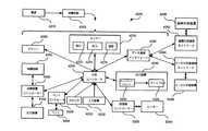
4.5 通信およびデータ管理システム
図7は本開示の態様を実施することのできる一例の通信システム700を表したものである。この一例は本明細書に記載の開示の範囲または特徴の実用性を制限すると考えるべきでない。この一例においてシステム700はサーバー710、患者装置720,730および740、記憶システム750、さらに計算装置(コンピューティングデバイス)760を含む。これらの装置はそれぞれネットワーク4282を通じて通信する。システム700は任意のサイズのネットワークに合わせることができる。例えば、3つの患者装置720、730および740しか示されていないが、システム700は任意の数の患者装置を含むことができる。4.5 Communication and Data Management System FIG. 7 illustrates an
患者装置720,730および740のそれぞれはRPT 4000、加湿器5000および患者インタフェース3000を含む1つまたはそれ以上の装置を含むことができる。さらに患者装置720,730および740のそれぞれは、遠隔地から異なる患者により作動させることができる。患者装置720にはコントローラー4230とメモリー4260のみが示されているが、それぞれの患者装置はRPT 4000、加湿器5000および患者インタフェース3000に関して上記の任意のコンポーネントを含むことができる。さらに患者装置720,730および740は、4282を通じてサーバー710または計算装置760と直接通信するように示されているが、患者装置のそれぞれは、外部計算装置(図示せず)を経由してネットワーク4282を通しても通信できる。例えば患者装置720は、ネットワーク4282を通してデータを送信するパーソナルコンピュータと通信できる。 Each of the
サーバー710は1つまたはそれ以上のプロセッサー712、メモリー714を含むことができ、汎用計算装置に典型的に使われているその他のコンポーネントを組み込むことができる。サーバー710のメモリー714は、プロセッサー712で実行できる命令715を含めプロセッサー712でアクセスできる情報を保存できる。メモリー714は、プロセッサー712で検索、操作または保存できるデータ718を含むこともできる。メモリーは、プロセッサーがアクセスできる情報を保存できる任意の非一時的なものでよい。命令716は、プロセッサー712で直接または間接に実行される命令を含む。この件については、「命令」、「適用」、「ステップ」および「プログラム」はここでは交換可能に使用できる。命令の機能、方法およびルーチンは以下に詳しく説明する。
データ718は、命令716にしたがってプロセッサー712によって検索、保存または修正できる。例えば、ここに記載の主題の件は、任意の特定のデータ構造によって制限されないが、データはコンピュータ・レジスターに保存可能で、テーブルは多数の異なる分野と記録を有しているので、リレーショナル・データベースまたはXMLドキュメントに保存することができる。データ718は、数、説明文、専用のコード、ポインター、他のネットワーク場所のようなその他のメモリーに保存されたデータへの参照のような関連の情報を識別または計算するのに十分な任意の情報であってよい。1つまたはそれ以上のプロセッサー712は、CPUのような従来のプロセッサーを含むことができ、またはASICのようなハードウエアに基づいたコンポーネントであってよい。
図7は、サーバー710のプロセッサーとメモリーとその他の構成要素、計算装置760、および患者装置720,730および740がそれぞれ1つのブロック内にあると機能的に示されているが、それぞれの装置のいろいろなコンポーネントは異なる物理的ハウジング内に収めることができる。例えば、メモリー714は、サーバー710のハウジングとは異なるハウジング内に位置するハ−ド・ドライブまたはその他の記憶媒体であってよい。同様に、プロセッサー712は複数のプロセッサーを含んでよく、それらの一部またはすべては、サーバー710のハウジングとは異なるハウジング内に位置している。よって、プロセッサー、コンピュータ、計算装置またはメモリーを参照することは、並行して作動するまたは作動することのないプロセッサー、コンピュータ、計算装置またはメモリーの集まりを参照することを含むと理解されたい。いくつかの機能は、単一のプロセッサーを有する単一の計算装置で生じているとここでは記述されているが、本開示のいろいろな態様は、ネットワーク4282を介して通信する等により、互いに情報を通信する複数の計算装置によって実施されることができる。 Although FIG. 7 functionally illustrates that the processor, memory and other components of the
多くの場合、患者装置720,730および740は無線通信を用いてネットワーク4282と通信するのが望ましい。しかしネットワーク4282およびここに記載の介在ノードは、ネットワークがインターネット、ワールドワイドウエブ、特殊なイントラネット、広域ネットワーク、ローカルネットワークまたは携帯電話ネットワークの一部であり得るように、いろいろなプロトコルとシステムを使用して相互接続できる。ネットワークは、例えばイーサネット(登録商標)、Wi−FiおよびHTTP、1つまたはそれ以上の企業独自のプロトコル、およびそれらの各種組み合わせ、のような標準通信プロトコルを利用できる。上述のように情報を送信または受信すると、或る利点が得られるが、本書に記載の主題のその他の態様は、情報の送信の任意の特定の態様に制限されない。 In many cases, it is desirable for
サーバー710は、ネットワーク4282を経由して記憶システム750、計算装置760および患者装置720,730および740と通信できる1つまたはそれ以上の通信サーバーを含む。以下に詳細に記述するように、サーバー710は、ソフトウエアおよびファームウエアの更新716を、ネットワーク4282を介して患者装置720,730および740に送信できる。次に、患者装置720,730および740は、命令セット726の形態のソフトウエアおよびファームウエアにしたがってデータをサーバー710に送信する。
計算装置760はサーバー710と同様に構成でき、1つまたはそれ以上のプロセッサー762、メモリー764および上記の命令を含む。このような計算装置のそれぞれは、臨床医の使用を意図した個人の計算装置でよく、中央処理ユニット(CPU)、データと命令を保存するメモリー(例えば、RAMと内部ハード・ドライブ)、ディスプレイ766のようなディスプレイ(例えば、スクリーンを有するモニター、タッチスクリーン、プロジェクター、テレビ、または情報を表示できるそのほかの装置)およびユーザー入力装置768(例えば、マウス、キーボード、タッチスクリーンまたはマイクロホン)のような個人用の計算装置に関して使用されるすべてのコンポーネントを有する。 The
4.6 一例の方法
上記のように、図7に示す患者装置720,730および740のそれぞれは、RPT 4000、加湿器5000および患者インタフェース3000を含む1つまたはそれ以上の医療装置を含むことができる。上述の動作を実行するにあたり、患者装置720,730および740は、ソフトウエアまたはファームウエアを含む命令セット726を実施することができる。図4cの関連で説明したようにRPT4000は、加湿器コントローラー5250および治療装置コントローラー4240のような複数のコントローラーを含むことができる。これらのコントローラーのそれぞれは特定の命令セット726に関して作動する。したがってそれぞれの命令セットは、上述したコンポーネントを含む、患者装置の特定のコンポーネントに関連する。例えば図7に戻れば、多数のモジュールを含むと示されている患者装置720は、通信モジュール721、加湿器モジュール723および警報モジュール725を含む。これらのモジュールのそれぞれは、異なる命令セット726にアクセスし、かつこれを実施することができる。もう1つの実施例において、特定の命令セット726は、上述の任意のモジュールを含む、1つ以上のモジュールによって実施されることができる。4.6 Example Method As described above, each of the
患者装置720,730および740はそれらの個別の患者によって使用され、命令セット726への更新が利用可能になりかつ必要となる。これらの更新は、特定の機能を改善すること、または装置の1つまたはそれ以上のモジュールの動作態様の識別された問題を修正することに関連している。このように、場合によっては、更新は、患者装置の効果的な管理に必須で、患者の安全にも必須である。本開示の1つの態様によれば、1つまたはそれ以上の命令セット726は通信ネットワーク4282を通して自動的に更新できる。特にサーバー710は1つまたはそれ以上の命令セット更新716を、1つまたはそれ以上の患者装置720,730および740へ送信できる。命令セット更新716を受信すると、それぞれの患者装置720,730および740は、送信された命令セット更新716で指示された態様で命令セット726を変更できる。このように患者装置は容易にアップグレードでき、さもなければ遠隔でカスタマイズでき、患者は患者装置を臨床医またはサービスセンターへ持参する必要はない。
1つの態様において、特定の患者装置を特定の更新を受信できるものとして、または受信するのに適したものとして選択できる。例えばサーバー710は、患者装置720が特定の命令セット更新716を受信すべきであるが患者装置730と740はそうでないと決めることができる。特定の更新を受信する特定の患者装置を識別するために、サーバー710はそれぞれの患者装置720,730および740のコンフィギュレーション(構成)・データ718を維持できる。コンフィギュレーション・データ718は、通し番号、患者装置によって現在組込まれているソフトウエアとファームウエアのバージョンの識別およびハードウエアのバージョン番号を含む特定の患者装置を識別するのに使用できる任意の情報を含むことができる。コンフィギュレーション・データ718は、以前に患者装置に送信された命令セットの更新の記録および送信された命令セット更新が首尾よく患者装置に適用されたかまたはされなかったかの指示も含む。さらにコンフィギュレーション・データ718は1つの特定の患者装置に関してはっきりと異なる情報に限定されず、多数の患者装置に適用できる情報を含むことができる。例えば、コンフィギュレーション・データ718は、患者装置のサプライヤーまたは小売店の識別ならびに患者装置が使用されている場所または領域を含むことができる。代替として、更新は、特定の更新によって修正可能な故障条件のようなその他の要素でトリガーできる。 In one aspect, a particular patient device can be selected as being able to receive or suitable for receiving a particular update. For example,
コンフィギュレーション・データ718は、登録プロセスを経て患者装置720,730および740によって提供される。例えば、患者装置720はネットワーク4282経由でサーバー710にコンフィギュレーション・データ728を送信する。サーバー710は次いで受信したコンフィギュレーション・データ728をコンフィギュレーション・データ718としてメモリー714に保存する。患者装置のコンフィギュレーション・データ718の登録は、患者が患者装置を始めて使用した時に生じる。さらにコンフィギュレーション・データ718は、コンフィギュレーション・データ728で生じる任意の変更時にサーバー710で更新される。例えば患者装置720は、その加湿器モジュール723のファームウエアを第1のバージョンから第2のバージョンへ首尾よく更新したとの通知をサーバー710に送信できる。サーバー710は次いでコンフィギュレーション・データ718を更新して、患者装置720が現在加湿器モジュールのファームウエアの第2のバージョンを組み込んでいることを示す。1つの実施例において、患者装置720は始動の度にその現在のコンフィギュレーション・データ728をチェックして、コンフィギュレーション・データ728における任意の変更をサーバー710に報告する。
1つの態様によれば、計算装置760のユーザーは特定の患者装置を選択してサーバー710と通信しながら更新する。例えば、計算装置760のユーザーは、それにより計算装置760が特定の患者装置720、730および740に対する特定の更新716を指定できるサーバー710とのインタフェースを提供するウエブサイトにアクセスできる。更新を実施すべき患者装置を識別するために、計算装置760は、ある基準を満足する患者装置を求めてサーバー710のメモリー714を検索する。例えば、計算装置760のユーザーは、特定のソフトウエア・バージョンを組込んでいる全ての患者装置または特定の範囲内の通し番号を識別するようにサーバー710に要求できる。もう1つの実施例では計算装置760は、特定の小売業者から購入したすべての患者装置のリストを要求できる。 According to one aspect, a user of
計算装置760のユーザーは、サーバー710経由で更新すべき患者装置を識別できる。1つ以上の可能性のある更新がある場合は、ユーザーは患者装置に提供すべき特定の更新716を識別または選択しなければならない。特定の更新を識別する場合、ユーザーは患者装置のどのコンポーネントを更新すべきか、またコンポーネントによって実装されるべきソフトウエアまたはハードウエアの特定のバージョンを識別できる。例えば、計算装置760のユーザーは、サーバー710に対し、患者装置720および730に加湿器モジュール723の更新716を提供するように要求し、その更新は加湿器ファームウエアのバージョン3.1に関するものであることを要求する。サーバー710は次いで選択した更新716を患者装置720と730に送信する。ファームウエアのバージョン3.1は、患者装置720と730によって現在組込まれている設定より新しいまたは異なる設定を含む。これらの新しい設定は、患者装置720と730がファームウエアのバージョン3.1をインストールすれば組み込むことができる。更新716を選択し、選択された更新716を送信するプロセスは、単一のサーバー710で実行でき、代替として1つ以上のサーバー710によって実行できる。例えば、計算装置760は通信サーバー710に対して更新依頼を行うことができる。通信サーバーは次いでこの依頼をダウンロードサーバーに送信し、サーバーは選択した更新を指定された患者装置へ送信する。 A user of
命令更新データは下記の1つを含むこともできる;命令更新フォームを何処で入手するかを明記したデータ、例えば、ホストサーバー、ポート、ファイル名;大容量の装置更新が効果的に管理できるように各装置の更新を実行するスケジュール時間;更新を適用すべきことを患者に確認する依頼をすべきかどうか;患者の治療が停止されるまで更新を適用すべきでないとの命令;必要な場合、まだ生じていないアップグレードのキャンセルを可能にするデータ構造と機能性;単一の操作で大量のアップグレードを依頼するバッチ能力ならびに単一の操作でこれらのアップグレードのステータス、リスト中どのアップグレードが成功したか、どれが失敗したか、どれが開始されていないか、等を後でチェックする能力。 Instruction update data can also include one of the following; data specifying where to obtain the instruction update form, eg host server, port, file name; large volume device updates can be effectively managed Scheduled time to perform each device update; whether to ask the patient to confirm that the update should be applied; an instruction that the update should not be applied until the patient's treatment is stopped; Data structures and functionality that allow cancellation of upgrades that have not yet occurred; batch capabilities to request large numbers of upgrades in a single operation, as well as the status of these upgrades in a single operation, which upgrades in the list were successful Ability to check later, which failed, which was not started, etc.
更新716を患者装置720、730および740に提供する場合、サーバー710は更新が首尾よくダウンロードされたことの検証に使用できる検証データを送信することもできる。それぞれの更新716は検証データを含む。検証データはチェックサム、巡回冗長検査または更新ファイルのサイズの識別の形態をとる。例えばサーバー710は、チェックサムを含む更新716を患者装置720に送信できる。患者装置720は受信した更新716とチェックサムを比較し、更新すべてを受領したかどうか決定する。もしダウンロードされた更新がチェックサムと一致すれば、患者装置はその更新をインストールし、インストールが成功したとの指示をサーバー710に送信する。しかし、もしダウンロードした更新がチェックサムと一致しないと、患者装置はその更新をインストールせず、インストールが生じなかったとの指示をサーバー710に送信できる。 When providing
サーバー710から患者装置720への送信は1つ以上のコンポーネントのための更新を含む。例えば、特定の更新716はサーバー710から患者装置720へ送信され、通信モジュール721と加湿器モジュール723に対する命令セット726のように、複数のコンポーネントに対する複数の命令セットを修正する。もう1つの実施例において、特定の命令セット726は複数のコンポーネントによって組み込まれ、この命令セット726の修正がこれら複数のコンポーネントの修正を引き起こす。複数の更新を単一の患者装置720に送信しかつ適用することもできる。送信に複数の更新716が含まれている場合、サーバー710は、更新が発生する順序を識別できる。次いで送信を受信した患者装置は、サーバー710によって指定された順序に従って更新716を組み込む。命令セットの最終バージョンが組み込まれるように、患者装置の1つのコンポーネントは、2回以上の更新が必要とされる場合がある。例えばバージョン3.0をインストールする前に、患者装置720は命令セットのバージョン2.0をダウンロードしてインストールする必要がある。従ってコンフィギュレーション・データ718は、特定の更新716を現在インストールできる患者装置720、730および740の識別ならびに特定の更新716をインストールするためにインストールしなければならないその他の更新の識別を含むことができる。もう1つの実施例において送信された更新716は、更新716をインストールするために必要な命令セット726のバージョンまたは複数のバージョンの識別を含むことができる。更新716をインストールするに先立ち、患者装置720は更新716で識別された要求されたバージョンを現在組込んでいるバージョンと比較できる。要求されるバージョンのうちの1つを患者装置720が現在組み込んでいない場合、患者装置720は、更新716のインストールを避けることができる。 The transmission from
患者装置720は、患者装置720が、更新716によって識別された、指定されたビルド標準(build standard:内蔵標準)を満足するかどうか決定し、その決定に基づいて更新716のインストールを実行するかまたは避ける。例えば識別されたビルド標準は、インストールすべき更新に必要なコンポーネントの組み合わせを含む。患者装置720は、それが識別されたコンポーネントの組み合わせを使用しているか決定するなどして、それが識別されたビルド標準を満足しているかどうか決定できる。識別されたコンポーネントが患者装置720で使用されておれば、これらのコンポーネントは更新716に従って更新できる。しかし患者装置720が1つまたはそれ以上の識別されたコンポーネントを含んでいなければ、患者装置720は更新716のインストールを避けることができる。1つの実施例において、患者装置720は患者装置720が含んでいないまたは使用していないコンポーネントに関連する更新716の部分のみ、インストールを避けることができるが、更新716の他の部分のインストールは進める。 The
1つの態様に従って患者装置はスケジュール通りに更新できる。例えば計算装置760のユーザーは、特定の患者装置が特定の更新716を受信することになっている日付を識別するなどして、更新のスケジュールをサーバー710に提供することができる。サーバー710は次いでスケジュールに従って更新716を送信できる。1つの実施例においてスケジュールはそれぞれの患者装置に対するコンフィギュレーション・データ718に組み込むことができる。このようにして、多数の患者装置に適用する更新を、例えば数週間または数か月の延長された期間にわたり適用することができ、ネットワーク4282がある時間に送信しなければならない負荷を低減できる。患者装置が更新716を受信するよう予定されている場合、サーバー710は更新依頼を送信できる。更新依頼はSMSメッセージまたはその他の肩たたき送信の形態をとることができる。サーバー710から更新依頼を受信すると患者装置720は、その更新を受け取る準備ができているとの指示で応答する。この更新は次いで患者装置720に送信されインストールされる。サーバー710は発生することになっていた更新716をキャンセルすることもできる。例えば計算装置760のユーザーは、特定の更新716が1つまたはそれ以上の患者装置720、730、および740に対してキャンセルすべきとの依頼を送ることができる。計算装置760の要求に応じて、サーバー710は特定の更新716を予定された更新のリストから除去することができる。更新が既に1つまたはそれ以上の患者装置に送信されたがまだインストールされていない場合は、サーバー710は更新のキャンセルを1つまたはそれ以上の患者装置に送信する。更新キャンセルを受信すると、患者装置720、730、および740は受信した更新716がインストールされる前にメモリーから削除できる。 According to one aspect, the patient device can be updated as scheduled. For example, a user of
代替として送信は特定の適切な日でよいが、それぞれの装置は更新を特定の後日に組み込むよう指示されてよい。サーバー710から更新を受信した後、患者装置720は更新をインストールする前にいろいろな理由で待つことができる。例えば更新を受信した時に患者が患者装置720から治療を受けている時、患者装置720は更新をインストールする前に患者の治療が終了するまで待つことができる。こうすれば患者の治療が中断されるまたは更新のインストールでマイナスの影響を受けることを避けることができる。1つの態様において更新は、患者装置を使用している間にそれをインストールしてよいかどうかを指示できる。具体的には、更新が実施されている時、患者装置によって実施できる特定の操作を指示できる。例えば更新716は、患者装置が呼吸治療を提供している間に行われる操作に関係のない通信モジュール721のみに関連する。従って更新716は、患者装置720が呼吸治療を提供するように使用中である間にインストールしてよいと指示する。インストール中は患者装置720は患者装置が更新されていることを示す通知を表示する。この通知は、患者が患者装置の電源をオフにしてはならないことおよび患者装置を特定の方法で使用する前に更新が完了するのを患者は待つべきであることを示すメセージを表示することを含む。1つの実施例において、患者装置720は更新がインストールされる前に患者からの確認を要求する。さらに、或る期間にわたって、多くの装置が新しいソフトウエアをダウンロードするが、ダウンロードされた更新は、マーケティングまたは通信の目的で、すべての装置に同じ日にインストール可能である。 Alternatively, the transmission may be on a specific appropriate date, but each device may be instructed to incorporate the update on a specific later date. After receiving the update from
1つの態様によれば、計算装置760のユーザーはサーバー710に更新716のステータスを問い合わせることができる。例えば計算装置760は、特定の更新716をまだ受信していないまたはまだインストールしていないこれらの患者装置の識別を要求できる。さらに計算装置760は1つまたはそれ以上の更新716がインストールされたすべての患者装置のリストならびに更新716の送信とインストールに関して生じたエラーに関する情報を要求できる。さらにサーバー710は計算装置760に、特定の患者装置が現在組込中のソフトウエアとファームウエアのバージョンのような現在の命令セットのリストを提供する。例えば計算装置760は患者装置720によって組み込まれた命令セット726のリストをサーバー710に問い合わせることができる。サーバー710はコンフィギュレーション・データ718にアクセスして、問い合わせのあった情報を識別しその情報を計算装置760に送信する。計算装置760は問い合わせを作成し、ウエブサイトまたはいくつかのほかのサーバー・インタフェースにアクセスすることにより、問い合わせした情報をサーバー710から受け取る。サーバー710は患者情報の機密を維持するために、問い合わせに関する識別情報とパスワードを提供するように計算装置760に要求する。 According to one aspect, a user of
図8はシステム700の患者装置720のような、患者装置によって実施されるフローチャート800を示す。上記のように患者装置は命令のセットを保存しかつ実施することができる。ブロック802において患者装置は、現在患者装置にアクセスできるソフトウエアまたはファームウエアのような命令のセットを組み込むことができる。命令のセットは患者装置内の複数のコンポーネントの操作に関連しており、単一の場所に保存する必要はない。命令のセットを組み込む場合、患者装置はネットワーク経由でデータを1つまたはそれ以上の外部装置に送信できる(ブロック804)。例えば患者装置720は、ネットワーク4282を経由して患者装置720の患者の使用に関するデータを、1つまたはそれ以上の命令にしたがって送信できる。この送信は患者が患者装置を使用した日付と時間に関する情報を含む。患者装置はサーバー710のような外部装置から送信を受信し、受信した送信が1つまたはそれ以上の命令セットの更新に関連しているかどうか決めることができる(ブロック806)。例えば患者装置は、更新データはサーバーの特定のアドレスのような特定の場所においてアクセスできることを示す送信を受信できる。更新が受信されない場合は、患者装置は現在の命令セットを実装し続けてよい(ブロック802)。更新の指示を受信した場合、患者装置は、識別されたアドレスにおける更新ファイルを要求またはこれにアクセスする等により、更新データを受け取ることができる。 FIG. 8 shows a
患者装置は更新に関してエラーがあるかどうかを決めることができる(ブロック808)。例えば上記のように、患者装置は更新をチェックサムと比較して更新をすべて受領したと決定する。さらに患者装置は、現在組込まれている命令セットのバージョンが、更新をインストールするのに必要なバージョンのうちの1つと一致するかどうか決定する。更新に関してエラーがあると決定された場合、患者装置はエラー通知を送信する(ブロック810)。例えば患者装置720は通知をサーバー710に送信して、更新が提供されたチェックサムと一致しなかったことを示す。この通知には更新の再送信の要求も含む。 The patient device can determine if there is an error regarding the update (block 808). For example, as described above, the patient device compares the update with the checksum and determines that all updates have been received. In addition, the patient device determines whether the currently installed version of the instruction set matches one of the versions required to install the update. If it is determined that there is an error with respect to the update, the patient device sends an error notification (block 810). For example, the
更新に関してエラーが検出されなければ、患者装置は更新(ブロック812)をインストールできる。上記のように、更新は1つまたはそれ以上の命令セットを修正することを含むことができる。修正には命令セットの一部を削除すること、命令セットに追加すること、ならびにオリジナルの命令セットを全く新しい命令セットで置き換えることが含まれる。上述したように、更新は、患者装置の異なるコンポーネントに対する命令セットを含む、種々の命令セットに対する修正を含む。更新をインストールすると、患者装置はチェックを行ってインストールが成功したかどうかを決定する。これには更新されたコンポーネントのそれぞれのチェックも含む(ブロック814)。インストールが不成功であれば、患者装置はエラーの通知を送信する(ブロック810)。さらに患者装置はオリジナルに戻って、オリジナルの命令セットをブロック802に従って組み込む。インストールが成功と決定された場合、患者装置はサーバー710のような外部装置に通知を送信して更新がインストールされたと伝える(ブロック816)。患者装置は、ブロック802に従い、更新された命令セットを含む、現在の命令セットにアクセスし、それを実装することもできる。 If no error is detected for the update, the patient device can install the update (block 812). As described above, the update can include modifying one or more instruction sets. Modifications include deleting part of the instruction set, adding to the instruction set, and replacing the original instruction set with a completely new instruction set. As described above, updates include modifications to various instruction sets, including instruction sets for different components of the patient device. When the update is installed, the patient device checks to determine if the installation was successful. This includes checking each of the updated components (block 814). If the installation is unsuccessful, the patient device sends an error notification (block 810). Further, the patient device returns to the original and incorporates the original instruction set according to block 802. If the installation is determined to be successful, the patient device sends a notification to an external device such as
図9は、システム700のサーバー710を含む、開示したシステムの計算装置で実施されるフローチャート900を示す。ブロック902においてサーバーは1つまたはそれ以上の基準を満たす患者装置の識別に対する問い合わせを受信する。例えば上記のように、サーバー710は計算装置760から問い合わせを受ける。この問い合わせは、計算装置760によって提供された1つまたはそれ以上の基準を満たすすべての患者装置の識別を探すことができる。この基準は、患者装置が位置している領域、患者装置の通し番号、ならびに患者装置によって現在組込まれているソフトウエアとファームウエアのバージョンのような患者装置の多数の態様または特徴に基づいている。サーバーは受信した問合せに応答してコンフィギュレーション・データにアクセスし(ブロック904)、識別された基準が満足されている患者装置を識別するデータを送信することによってその問い合わせに応答する(ブロック906)。 FIG. 9 shows a
サーバーは次いで1つまたはそれ以上の患者装置に送信する1つまたはそれ以上の更新に対する要求を受信する(ブロック908)。例えば上記のように計算装置760は、計算装置760のユーザーによって提供された基準を満足する患者装置720、730および740のサーバー710からのリストを受信する。ユーザーは次いで患者装置720、730および740に送信する特定の更新716を選択する。ブロック908の要求を受けると、サーバーは更新データにアクセスし(ブロック910)、受信した要求で識別された患者装置に更新データを送信する(ブロック912)。ブロック902〜908における機能は、異なる順序で実施されてよい。例えばサーバーは、更新依頼を受信すると同時に(またはその前にも)装置を特定のコンフィギュレーションで識別する依頼を受け取り、明記された基準を満足する装置にのみ更新を送る。さらに、ブロック912に従って更新データを患者装置に送信するために、ブロック910を実施する必要はない。例えばサーバー710は更新データを、更新ファイルが保存されている場所を示すアドレスとして送信できる。アドレスで識別された場所は、サーバー710上またはその他の場所でよい。このように、更新ファイルのアドレスは、識別された場所に保存されている実際の更新ファイルデータにアクセスするようサーバー710に要求することなく、患者装置に提供できる。 The server then receives a request for one or more updates to send to one or more patient devices (block 908). For example, as described above,
サーバーは更新の送信および/またはインストールが成功したかどうかも決定することができる(ブロック914)。例えばサーバーはそれぞれの患者装置から、エラー通知または更新が首尾よくインストールされたとのメッセージのいずれかを受信する。更新の送信にエラーが発生するとサーバーは、エラーが発生した各患者装置に更新データを再度送信することができる(ブロック912)。代替として、実際の更新ファイル(新しいソフトウエア)は、サーバー710によって装置に押し下げられるのではなく、ファイルサーバーから治療装置自身によって要求することができる。患者装置の更新は、更新が1つまたはそれ以上の条件の発生に付随することができるということにおいて、直ちに発生しなくてもよい。例えば更新データは、装置が治療を200時間提供した後に患者装置が更新をインストールすべきであるということを指示することができる。したがってブロック912とブロック914の間にかなりの時間の経過がある。しかし送信とインストールが成功すれば、サーバーは保存されたコンフィギュレーション・データを改定して、1つまたはそれ以上の患者装置が送信された更新に対応する命令を現在組込中であることを示し(ブロック916)、更新が成功したことを報告する(ブロック918)。例えば1つまたはそれ以上の患者装置が首尾よく更新されると、サーバー710は計算装置760にメッセージを送信して更新が完了したことをユーザー、例えば技術者、に通知する。このメッセージは、更新を首尾よくインストールした特定の患者装置または患者装置のグループを識別する。 The server may also determine whether the sending of the update and / or the installation was successful (block 914). For example, the server receives from each patient device either an error notification or a message that the update was successfully installed. If an error occurs in sending the update, the server may send the update data again to each patient device in which the error occurred (block 912). Alternatively, the actual update file (new software) can be requested by the therapy device itself from the file server, rather than being pushed down by the
図8と図9で説明した命令は単一装置で実施できるが、代替として1つ以上の装置で実施できる。例えばパーソナルコンピュータが1つまたはそれ以上の上記命令を実施できるように、患者装置はワイヤレスネットワークを通じてパーソナルコンピュータと通信できる。図8と図9で参照したサーバーも複数のサーバーを含むこともできる。図8と図9に示す特定の操作に関し、いろいろな操作をフローチャート800と900に追加、または、から除外することができる。更にいろいろな操作をフローチャート800と900に示すのと同じ順序で実施する必要はない。例えばサーバーは更新情報を治療装置に送ってどの更新が必要であるか、それを何処から入手するか(ホスト、ポート、ファイル名)およびそれをどのように検証するか(例えば、チェックサム/CRC)を指示する。次に、治療装置通信モジュールは、更新ファイル(命令)を、指定されたホスト(サーバー)から要求する。この多少異なる機能ダイアグラムでは、大容量のソフトウエアをダウンロードする負荷を、必要なら、図7に示すようなサーバー710からだけではなく、多数のサーバーにわたって配分することができる。さらに治療装置は、送信エラーがあれば明記されたサーバーそのものから、サーバー710の介入なしに更新ファイル(即ち新しいソフトウエア)を再度要求できる。エラーが通知されると、サーバーは、上記のように操作を再度試みることも可能である。 The instructions described in FIGS. 8 and 9 can be implemented on a single device, but can alternatively be implemented on one or more devices. For example, a patient device can communicate with a personal computer over a wireless network so that the personal computer can implement one or more of the above instructions. The server referred to in FIGS. 8 and 9 can also include a plurality of servers. With respect to the specific operations shown in FIGS. 8 and 9, various operations may be added to or excluded from the
4.7 用語解説
本技術の或る形式において、1つまたはそれ以上の以下の定義を適用してよい。本技術のそのほかの形態において、代替の定義を適用できる。4.7 Glossary In some forms of the technology, one or more of the following definitions may apply. In other forms of the technology, alternative definitions can be applied.
4.7.1 一般
空気:例えば空気に補給酸素を含めるように、空気を取り入れて呼吸ガスに含める。4.7.1 General Air: Intake air and include it in the breathing gas, for example, so that supplemental oxygen is included in the air.
持続的気道陽圧法(CPAP)治療:CPAP治療は、空気を大気に関して連続して陽圧である圧力で気道の入口へ適用することであり、好ましくは圧力は患者の呼吸サイクルを通じてほぼ一定である。いくつかの形態では、気道の入口での圧力は単一の呼吸サイクルで水中数センチ変動し、吸入中は僅か高く、呼気中は僅か低い。いくつかの形態において、気道入口における圧力は呼気中は僅かに高く、吸入中は僅かに低い。いくつかの形態において、圧力は患者の異なる呼吸サイクル間で変動する。例えば、患者の上気道の一部閉塞の兆候の検出に対応して増加し、上気道の一部閉塞の兆候がなければ低下する。 Continuous positive airway pressure (CPAP) treatment: CPAP treatment is the application of air to the airway inlet at a pressure that is continuously positive with respect to the atmosphere, preferably the pressure is approximately constant throughout the patient's respiratory cycle . In some forms, the pressure at the entrance of the airway fluctuates several centimeters in water in a single breathing cycle, being slightly higher during inhalation and slightly lower during exhalation. In some forms, the pressure at the airway entrance is slightly higher during expiration and slightly lower during inhalation. In some forms, the pressure varies between different breathing cycles of the patient. For example, it increases in response to detection of a sign of partial obstruction of the patient's upper airway and decreases if there is no sign of partial obstruction of the upper airway.
4.7.2 材料
シリコンまたはシリコン・エラストマー:合成ゴム。本明細書において、シリコンは液体シリコンゴム(LSR)または圧縮形成シリコンゴム(CMSR)を指す。市販のLSRの一形態は、Dow Corningが製造しているSILASTICである(この商標で販売されている製品範囲に含まれている)。LSRを製造しているもう1社はWackerである。特に明記のない限り、LSRの好ましい形態は、ASTM D2240に従って測定された約35から約45の範囲のショアA(またはタイプA)圧入硬度を有している。4.7.2 Material Silicon or silicon elastomer: Synthetic rubber. In this specification, silicon refers to liquid silicone rubber (LSR) or compression-formed silicone rubber (CMSR). One form of commercial LSR is SILASTIC manufactured by Dow Corning (included in the product range sold under this trademark). Another company that manufactures LSR is Wacker. Unless otherwise stated, preferred forms of LSR have a Shore A (or Type A) indentation hardness in the range of about 35 to about 45, measured according to ASTM D2240.
ポリカーボネート:ビスフェノール−Aカーボネートの典型的に透明な熱可塑性ポリマー。 Polycarbonate: A typically transparent thermoplastic polymer of bisphenol-A carbonate.
4.7.3 患者インタフェースの態様
抗呼吸停止バルブ(AAV):マスクシステムのコンポーネントまたはサブアセンブリーで、フェイルセーフの態様で大気に開放すると、患者の過剰なCO2再呼吸のリスクを低減する。4.7.3 Patient Interface Aspect Anti-breathing stop valve (AAV): A component or subassembly of a mask system that opens to the atmosphere in a fail-safe manner to reduce the patient's risk of excessive CO2 rebreathing .
エルボー:角部を通して方向が変わるように、空気の流れの軸を方向付けるコンジット。一形態において、角度は約90度でよい。もう1つの形態において、角度は90度以下でよい。このコンジットはほぼ円形の断面を有している。もう1つの形態において、コンジットは楕円形または長方形の断面を有することができる。 Elbow: A conduit that directs the axis of air flow so that the direction changes through the corners. In one form, the angle may be about 90 degrees. In another form, the angle may be 90 degrees or less. The conduit has a substantially circular cross section. In another form, the conduit can have an oval or rectangular cross section.
フレーム:フレームは、ヘッドギアとの2つまたはそれ以上の接続ポイント間の張力の負荷に耐えるマスク構造を意味する。マスクのフレームは、マスクにおいて非気密耐加重構造であってよい。しかしいくつかの形態のマスクフレームは、気密であってもよい。 Frame: Frame refers to a mask structure that withstands tension loads between two or more connection points with the headgear. The frame of the mask may be a non-hermetic load-resistant structure in the mask. However, some forms of mask frame may be airtight.
ヘッドギア:ヘッドギアは、頭に使用するようにデザインされた位置決めと安定化構造の形態を意味すると解釈してよい。好ましくは、ヘッドギアは患者インタフェースを呼吸治療の送達のために患者の顔の適切な場所に置きかつ保持するように構成された、1つまたはそれ以上の筋かい、ひも(紐)、および補強材の集まりを含む。いくつかのひもは、発泡体と織物の積層複合材のような柔らかく、柔軟で、弾性性のある材料で形成される。 Headgear: Headgear may be taken to mean a form of positioning and stabilization structure designed for use on the head. Preferably, the headgear is one or more braces, laces, and stiffeners configured to place and hold the patient interface in place on the patient's face for delivery of respiratory therapy Including a collection of Some strings are formed of a soft, flexible, elastic material such as a laminate of foam and fabric.
メンブレン:好ましくは、曲げに対して実質的に耐性を示さないが、伸ばすことには耐性を持った、典型的には薄いエレメントを意味すると解釈される。 Membrane: preferably taken to mean a typically thin element that is not substantially resistant to bending but resistant to stretching.
プレナムチャンバー:患者インタフェース・プレナムチャンバーは、例えばフルフェース・マスク(即ち鼻と口のマスク)、鼻マスクまたは鼻枕のような容量のある空間を囲む壁を有する患者インタフェースの一部を意味すると解釈され、この容量はその中に患者が使用中は大気以上に加圧された空気を有する。シェルは患者インタフェース・プレナムチャンバーの壁の一部を形成してよい。1つの形態において患者の顔の領域が、クッションまたはシールを経てプレナムチャンバーの壁の1つと隣接する。 Plenum chamber: patient interface A plenum chamber is understood to mean the part of a patient interface that has a wall surrounding a volumetric space such as a full face mask (ie nose and mouth mask), nasal mask or nasal pillow. This volume has air in it that is pressurized above the atmosphere during patient use. The shell may form part of the wall of the patient interface plenum chamber. In one form, the area of the patient's face is adjacent to one of the walls of the plenum chamber via a cushion or seal.
シール:名詞形(「a seal」)は,2つの面のインタフェースを通る空気の流れに意図的に耐性を示す構造またはバリアを意味すると解釈される。動詞形(「to seal」)は、空気の流れに抗することを意味すると解釈される。 Seal: The noun form (“a seal”) is taken to mean a structure or barrier that is intentionally resistant to the flow of air through the interface of two faces. The verb form (“to seal”) is taken to mean resisting air flow.
シェル:シェルは、曲げ、引張りおよび圧縮剛性を有する、湾曲した構造を意味すると解釈される。例えば、マスクの湾曲した構造壁を形成するマスクの一部がそうである。好ましくは、その全体の大きさと比較して相対的に薄い。いくつかの形態ではシェルには切子面がある。このような壁は気密性でなくてよいが、好ましくは気密性である。 Shell: Shell is taken to mean a curved structure having bending, tensile and compressive stiffness. For example, the portion of the mask that forms the curved structural wall of the mask. Preferably, it is relatively thin compared to its overall size. In some forms, the shell has a facet. Such walls may not be airtight, but are preferably airtight.
補強材:補強材は、別のコンポーネントの少なくとも1方向への曲げ耐性を増すようにデザインされた構造要素(構造コンポーネント)を意味すると解釈される。 Stiffener: Stiffener is taken to mean a structural element (structural component) designed to increase the bending resistance of another component in at least one direction.
筋かい:筋かいは、別のコンポーネントの少なくとも1方向への圧縮耐性を増すようにデザインされた構造要素(構造コンポーネント)を意味すると解釈される。 Brace: Brace is taken to mean a structural element (structural component) designed to increase the compression resistance of another component in at least one direction.
旋回台:(名詞)好ましくは独立して、好ましくは低トルク下で、共通軸の周りを回転するように構成されたコンポーネントのアセンブリー。一形態において旋回台は、少なくとも360度回転するように構築してよい。もう1つの形態において、旋回台は360度以下の角度で回転するように構築してよい。空気送達コンジットの状況で使用する場合は、コンポーネントのサブアセンブリーは好ましくは円筒コンジットの一対組み合わせを含む。好ましくは使用中は、旋回台からの空気の漏れは、ほとんどないかまたは全くない。 Swivel: (noun) An assembly of components configured to rotate about a common axis, preferably independently, preferably under low torque. In one form, the swivel may be constructed to rotate at least 360 degrees. In another form, the swivel may be constructed to rotate at an angle of 360 degrees or less. When used in the context of a pneumatic delivery conduit, the component subassembly preferably includes a paired combination of cylindrical conduits. During use, there is little or no air leakage from the swivel.
固定具:固定具は張力に抗するようにデザインされた構造コンポーネントを意味すると解釈できる。 Fixture: Fixture can be taken to mean a structural component designed to resist tension.
ベント:(名詞)吐き出した二酸化炭素(CO2)の洗い出しと酸素の供給(O2)を行うため、マスクの内部またはコンジットから周囲空気への空気の漏れの率を慎重に制御できる構造。Vent: (noun) A structure that can carefully control the rate of air leakage from the inside of the mask or from the conduit to the surrounding air in order to wash out exhaled carbon dioxide (CO2 ) and supply oxygen (O2 ).
4.8 その他の注記
本特許文献の開示の一部は、著作権保護にあたる事項を含んでいる。著作権の所有者は、特許庁の特許ファイルまたは記録にそれが載っている限り、誰かが特許文献または特許の開示をフクシミリ複製することについて異議を唱えることはない。載っていなければ、何であれ著作権を留保する。4.8 Other Notes A part of the disclosure of this patent document includes matters relating to copyright protection. The copyright owner will not challenge anyone to duplicate the patent document or patent disclosure as long as it appears in the patent office's patent file or record. If it is not listed, reserve copyright.
文脈で明確に記載されていなければ、また値の範囲が記載されていなければ、それぞれの介在する値は、その範囲の上限と下限の間で、下限の単位の1/10まで、およびその記述された範囲の任意のそのほかの記述されたまたは介在する値は、該技術に包含される。これらの介在範囲の上限と下限は、記載された範囲における任意の具体的に除外される限界を条件として、介在範囲に独立に含めてよく、本技術の範囲内に包含される。記述した範囲が一つまたは両方の制限を含む場合、これらの含まれた制限のいずれかまたは両方を除いた範囲も該技術に含まれる。 Unless otherwise stated in the context and unless a range of values is stated, each intervening value is between the upper and lower limits of the range, up to 1/10 of the lower limit unit, and the description Any other stated or intervening values in the stated ranges are encompassed by the technique. The upper and lower limits of these intervening ranges may be included independently in the intervening ranges, subject to any specifically excluded limits in the stated ranges, and are included within the scope of the present technology. Where the stated range includes one or both of the limits, ranges excluding either or both of those included limits are also included in the art.
更に、一つまたはそれ以上の値が、技術の一部としてここに組み込まれていると記載されている場合、特記のない限り、このような値は近似することができ、実際的な技術の実施が許容するまたは必要とする範囲まで、このような値は任意の適当な有意桁まで利用できることを理解されたい。 Further, where one or more values are stated to be incorporated herein as part of the technology, such values can be approximated, unless otherwise specified, and are It should be understood that such values can be used to any suitable significant digit, to the extent permitted or required by practice.
特に定義されていない限り、本明細書で使用するすべての技術的用語および科学的用語は、この技術が属する当業者の一人によって共通して理解されるのと同じ意味を有している。ここに記載のものに類似したまたは同等な任意の方法また材料も、本技術の実践またはテストで使用できるが、限られた数の例示的方法と材料がここに記載されている。 Unless defined otherwise, all technical and scientific terms used herein have the same meaning as commonly understood by one of ordinary skill in the art to which this technology belongs. Although any methods or materials similar or equivalent to those described herein can also be used in the practice or testing of the present technology, a limited number of exemplary methods and materials are described herein.
特定の材料がコンポーネントを構築するのに使用されると確認された場合、同様の特性を有する明らかに代替の材料を代替えとして使用できる。さらに、それとは反対に特記のない限り、ここに記載の任意のそしてすべてのコンポーネントは製造が可能と理解され、よって一緒にまたは別に製造することができる。 If it is determined that a particular material will be used to construct the component, a clearly alternative material with similar properties can be used as an alternative. Further, unless specified to the contrary, any and all components described herein are understood to be manufacturable and can be manufactured together or separately.
本明細書と付属の請求の範囲で使用される単数形「a」、「an」および「the」は、文脈で明確にそうでないと記述されていない限り、それらの複数形を含むことに留意すべきである。 Note that the singular forms “a”, “an”, and “the”, as used herein and in the appended claims, include their plural forms unless the context clearly dictates otherwise. Should.
ここで言及したすべての刊行物は、これら刊行物の主題である方法および/または材料を開示しかつ記述するために参照のため取り入れられた。ここで議論する刊行物は、それらの開示の目的で、本出願の出願日に先立ち提供された。ここに記載の何物も、本技術が、先行発明の理由でこのような刊行物に先行する資格を与えられないという承認として解釈されるべきではない。さらに記載の公開日が実際の刊行日と異なるかもしれず、それぞれ単独で確認する必要がある。 All publications mentioned herein are incorporated by reference to disclose and describe the methods and / or materials that are the subject of these publications. The publications discussed herein were provided prior to the filing date of the present application for the purposes of their disclosure. Nothing herein is to be construed as an admission that the technology is not entitled to antedate such publications for reasons of prior invention. Furthermore, the date of publication described may differ from the actual publication date, and each must be independently confirmed.
さらに本開示を解釈するのに、すべての用語は文脈と一致した最大限広範で合理的な態様で解釈すべきである。特に語句「comprise」と「comprising」は、エレメント、コンポーネントまたはステップを非排他的態様で参照するとして解釈すべきであり、参照したエレメント、コンポーネントまたはステップは、明示的に参照されていない他のエレメント、コンポーネントまたはステップとともに、存在するか、利用されるか、または組み合わされることを示す。 Further, for interpreting the present disclosure, all terms should be construed in the broadest and reasonable manner consistent with the context. In particular, the phrases “comprise” and “comprising” should be construed as referring to elements, components or steps in a non-exclusive manner, and the referenced elements, components or steps are other elements not explicitly referred to. Present, utilized, or combined with a component or step.
詳細な説明で使用される件名は、読者の参照を容易にするためにのみ含まれており、開示または特許請求の範囲にわたって見出される主題を制限するために使用してはならない。主題の見出しは請求項の範囲または請求項の制限範囲を解釈するのに使用してはならない。 The subject matter used in the detailed description is included only for ease of reference by the reader and should not be used to limit the subject matter found throughout the disclosure or the claims. The subject heading should not be used to interpret the scope of a claim or the scope of a claim.
本明細書に記載の技術は特定の実施例を参照して記述してきたが、これらの実施例は該技術の原理と適用の単なる例示であることを理解されたい。場合によっては、用語および記号は、該技術を実践するのに要求されない特定の詳細を暗示することがある。例えば、「第1の」および「第2の」という語句が特記のない限り使用されるが、それらは任意の順序を示すことを意図せず、はっきりと異なるエレメントを区別するために使用できる。さらに方法論におけるプロセス・ステップは順に記述または例示されてもよいが、このような順序は必要とされない。当業者は、このような順序が修正されてもよいことおよび/またはそれらの特徴が同時にまたは同期的に実施されてもよいことを認識するであろう。
従って、例示的な実施例に多数の変更が行われてもよく、該技術の趣旨および範囲から逸脱することなくそのほかの構成が考案され得ることを理解されたい。Although the techniques described herein have been described with reference to particular embodiments, it is to be understood that these embodiments are merely illustrative of the principles and applications of the techniques. In some cases, the terms and symbols may imply specific details that are not required to practice the techniques. For example, the terms “first” and “second” are used unless otherwise indicated, but they are not intended to indicate any order and can be used to distinguish distinct elements. Further, the process steps in the methodology may be described or illustrated in order, but such an order is not required. One skilled in the art will recognize that such an order may be modified and / or their features may be performed simultaneously or synchronously.
Accordingly, it should be understood that numerous modifications may be made to the exemplary embodiments and that other configurations may be devised without departing from the spirit and scope of the technology.
700 通信システム
710 サーバー
712 プロセッサー
714 メモリー
715 命令
716 命令セット更新
718 コンフィギュレーション・データ
720 患者装置
721 通信モジュール
723 加湿器モジュール
725 警報モジュール
726 命令セット
728 コンフィギュレーション・データ
720 患者装置
730 患者装置
740 患者装置
750 記憶システム
760 計算装置
762 プロセッサー
764 メモリー
766 ディスプレイ
768 ユーザー入力装置
1000 患者
3000 患者インタフェース
3100 シール形成構造
3200 プレナムチャンバー
3210 周辺
3300 位置決めと安定化構造
3400 ベント
3600 接続ポート
4000 RPT装置
4010 外部ハウジング
4012 外部ハウジングの上部
4014 外部ハウジングの下部
4015 パネル
4016 シャーシ
4018 ハンドル
4020 空気ブロック
4100 空気コンポーネント
4110 空気フィルター
4112 入口空気フィルター
4114 出口空気フィルター
4120 マフラー
4122 入口マフラー
4124 出口マフラー
4140 圧力装置
4142 送風機
4144 モーター
4144 ブラシレスDCモーター
4160 バックバルブ
4170 空気回路
4180 酸素補給
4200 電気的コンポーネント
4202 基板アセンブリーPCBA
4210 電源
4220 入力装置
4230 中央コントローラー
4232 時計
4240 治療装置コントローラー
4250 保護回路
4260 メモリー
4270 変換器
4272 圧力変換器
4274 流れセンサー
4276 モーター速度信号
4280 データ通信システム
4282 遠隔外部通信ネットワーク
4284 ローカル外部通信ネットワーク
4286 遠隔外部装置
4288 ローカル外部装置
4290 出力装置
4292 ディスプレイ・ドライバー
4294 ディスプレイ
4300 アルゴリズム
4330 圧力制御モジュール
5000 加湿器
5250 加湿器コントローラー
700
4210
Claims (32)
Translated fromJapanese1つまたはそれ以上のプロセッサーにより、複数の患者装置に関するコンフィギュレーション・データにアクセスするステップであって、前記複数の患者装置のそれぞれは、命令のセットを実装する、ステップと、
前記1つまたはそれ以上のプロセッサーにより、1つまたはそれ以上の基準を満たすコンフィギュレーション・データを有する1つまたはそれ以上の患者装置を、前記複数の患者装置から識別するステップと、
前記1つまたはそれ以上のプロセッサーにより、命令更新を前記1つまたはそれ以上の患者装置にネットワークを経由して送信するステップと、
前記1つまたはそれ以上のプロセッサーにより、前記命令更新をインストールした前記1つまたはそれ以上の患者装置のそれぞれに対する前記コンフィギュレーション・データを更新するステップと、
を含む方法。A method for updating a device providing medical care, comprising:
Accessing configuration data for a plurality of patient devices by one or more processors, each of the plurality of patient devices implementing a set of instructions;
Identifying, from the plurality of patient devices, one or more patient devices having configuration data that meets one or more criteria by the one or more processors;
Sending an instruction update by the one or more processors to the one or more patient devices over a network;
Updating the configuration data for each of the one or more patient devices installed with the instruction update by the one or more processors;
Including methods.
命令更新ファイルの場所を指定するデータ、
前記更新を前記装置のどのコンポーネントに適用すべきかに関する指示、
各装置に対して前記更新を実施するスケジュール時間、
前記更新が適用されるべきとの確認を要求すべきかどうかの指示、
該当する場合、患者の治療が停止されるまで前記更新を適用すべきでないとの指示、
まだ発生していない更新のキャンセルを可能にするデータ構造および機能性、
単一の操作において大量の更新を要求するバッチ能力、および
前記更新のステータスを示す単一の操作において、これらの更新のステータスをチェックする能力、
のうちの少なくとも1つを含む、請求項1から3のいずれか一項に記載の方法。The instruction update is
Data specifying the location of the instruction update file,
Instructions on which components of the device the update should apply to;
Schedule time for performing the update for each device,
An indication of whether to require confirmation that the update should be applied;
If applicable, an indication that the update should not be applied until patient treatment is discontinued;
Data structures and functionality that allow cancellation of updates that have not yet occurred,
The ability to request a large number of updates in a single operation, and the ability to check the status of these updates in a single operation that indicates the status of the update,
4. The method according to any one of claims 1 to 3, comprising at least one of the following.
1つまたはそれ以上のプロセッサーにより、患者装置の操作の第1の命令セットにアクセスするステップと、
前記1つまたはそれ以上のプロセッサーにより、前記第1の命令セットに従って第1の操作セットを実施するステップと、
前記1つまたはそれ以上のプロセッサーにより、遠隔計算装置からネットワークを経由して更新データを受信するステップと、
更新された命令セットを生成するため、前記1つまたはそれ以上のプロセッサーにより、前記更新データに従って前記第1の命令セットを更新するステップと、
前記1つまたはそれ以上のプロセッサーにより、前記第1の命令セットの更新が発生したことの確認を前記遠隔計算装置に送信するステップと、
前記1つまたはそれ以上のプロセッサーにより、更新された命令セットに従って第2の操作セットを実施するステップと、
を含む方法。A method for updating a device providing medical care, comprising:
Accessing a first instruction set of operation of the patient device by one or more processors;
Performing a first set of operations by the one or more processors according to the first set of instructions;
Receiving update data from a remote computing device over a network by the one or more processors;
Updating the first instruction set according to the update data by the one or more processors to generate an updated instruction set;
Sending, by the one or more processors, confirmation to the remote computing device that an update of the first instruction set has occurred;
Performing a second set of operations with the one or more processors according to an updated instruction set;
Including methods.
更新データの第2の送信を受信するステップと、
をさらに含む、請求項14〜16のいずれか一項に記載の方法。If the received update data is determined to be incomplete, sending an error notification to the remote computing device;
Receiving a second transmission of update data;
The method according to any one of claims 14 to 16, further comprising:
それぞれ命令のセットを実装する複数の患者装置に関するコンフィギュレーション・データにアクセスし、
1つまたはそれ以上の基準を満足するコンフィギュレーション・データを有する1つまたはそれ以上の患者装置を前記複数の患者装置から識別し、
命令更新を前記1つまたはそれ以上の患者装置に送信し、
前記命令更新をインストールした前記1つまたはそれ以上の患者装置のそれぞれに対して前記コンフィギュレーション・データを更新する、
ように構成されている、システム。A system for updating a device that provides medical care, including one or more computing devices, the one or more computing devices comprising:
Access configuration data for multiple patient devices, each implementing a set of instructions,
Identifying from the plurality of patient devices one or more patient devices having configuration data satisfying one or more criteria;
Sending a command update to the one or more patient devices;
Updating the configuration data for each of the one or more patient devices that have installed the instruction update;
Configured as a system.
命令更新ファイルの場所を指定したデータ、
前記更新を前記装置のどのコンポーネントに適用すべきかに関する指示、
前記更新をそれぞれの装置に対して実施するスケジュール時間、
前記更新を適用すべきとの確認を要求すべきかどうかの指示、
該当する場合に、患者の治療が停止されるまで前記更新を適用しないとの指示、
まだ発生していない更新のキャンセルを可能にするデータ構造および機能性、
単一の操作において大量の更新を要求するバッチ能力、および、
前記更新のステータスを示す単一の操作においてこれらの更新のステータスをチェックする能力、
のうちの少なくとも1つを含む、請求項22〜25のいずれか一項に記載のシステム。The instruction update is
Data specifying the location of the instruction update file,
Instructions on which components of the device the update should apply to;
A schedule time for performing the update on each device;
An indication of whether to require confirmation that the update should be applied;
If applicable, an indication not to apply the update until the patient's treatment is stopped;
Data structures and functionality that allow cancellation of updates that have not yet occurred,
Batch capability to request a large number of updates in a single operation, and
The ability to check the status of these updates in a single operation indicating the status of the updates;
26. A system according to any one of claims 22 to 25, comprising at least one of:
前記命令更新がインストールされたとの指示を前記1つまたはそれ以上の患者装置のそれぞれから受信し、
前記命令更新のインストールの成功を示すメッセージを前記1つまたはそれ以上の患者装置に送信する、
ようにさらに構成される、請求項22〜29のいずれか一項に記載のシステム。The one or more computing devices are:
Receiving instructions from each of the one or more patient devices that the instruction update has been installed;
Sending a message to said one or more patient devices indicating successful installation of said instruction update;
30. A system according to any one of claims 22 to 29, further configured as follows.
32. A system according to any one of claims 22-31, wherein the configuration data includes a record of command updates previously applied successfully or unsuccessfully to a particular patient device from a plurality of patient devices. .
Applications Claiming Priority (3)
| Application Number | Priority Date | Filing Date | Title |
|---|---|---|---|
| AU2014901999 | 2014-05-27 | ||
| AU2014901999AAU2014901999A0 (en) | 2014-05-27 | Remote respiratory therapy device management | |
| PCT/AU2015/050280WO2015179915A1 (en) | 2014-05-27 | 2015-05-27 | Remote respiratory therapy device management |
Related Child Applications (1)
| Application Number | Title | Priority Date | Filing Date |
|---|---|---|---|
| JP2020197854ADivisionJP7150801B2 (en) | 2014-05-27 | 2020-11-30 | Management of remote respiratory therapy devices |
Publications (3)
| Publication Number | Publication Date |
|---|---|
| JP2017519292Atrue JP2017519292A (en) | 2017-07-13 |
| JP2017519292A5 JP2017519292A5 (en) | 2018-07-05 |
| JP6857499B2 JP6857499B2 (en) | 2021-04-14 |
Family
ID=54697729
Family Applications (4)
| Application Number | Title | Priority Date | Filing Date |
|---|---|---|---|
| JP2016569746AActiveJP6857499B2 (en) | 2014-05-27 | 2015-05-27 | Management of remote respiratory therapy equipment |
| JP2020197854AActiveJP7150801B2 (en) | 2014-05-27 | 2020-11-30 | Management of remote respiratory therapy devices |
| JP2022154880AActiveJP7510980B2 (en) | 2014-05-27 | 2022-09-28 | Method and system for updating patient devices - Patents.com |
| JP2024101072AActiveJP7748506B2 (en) | 2014-05-27 | 2024-06-24 | Patient device and update method thereof |
Family Applications After (3)
| Application Number | Title | Priority Date | Filing Date |
|---|---|---|---|
| JP2020197854AActiveJP7150801B2 (en) | 2014-05-27 | 2020-11-30 | Management of remote respiratory therapy devices |
| JP2022154880AActiveJP7510980B2 (en) | 2014-05-27 | 2022-09-28 | Method and system for updating patient devices - Patents.com |
| JP2024101072AActiveJP7748506B2 (en) | 2014-05-27 | 2024-06-24 | Patient device and update method thereof |
Country Status (4)
| Country | Link |
|---|---|
| US (3) | US11116924B2 (en) |
| EP (3) | EP4241811B1 (en) |
| JP (4) | JP6857499B2 (en) |
| WO (1) | WO2015179915A1 (en) |
Cited By (2)
| Publication number | Priority date | Publication date | Assignee | Title |
|---|---|---|---|---|
| JP2022527110A (en)* | 2019-03-29 | 2022-05-30 | レズメド インコーポレイテッド | Saving, controlling and porting breathing settings from a remote server |
| JP2022551008A (en)* | 2019-11-14 | 2022-12-06 | レスメド・プロプライエタリー・リミテッド | Managing remote respiratory therapy devices |
Families Citing this family (38)
| Publication number | Priority date | Publication date | Assignee | Title |
|---|---|---|---|---|
| EP4169560B1 (en) | 2011-07-13 | 2025-09-17 | Fisher & Paykel Healthcare Limited | Bearing mount for a compressor or blower for providing respiratory assistance |
| EP3738638A1 (en) | 2012-03-15 | 2020-11-18 | Fisher & Paykel Healthcare Limited | Respiratory gas humidification system |
| GB2575894A (en) | 2012-04-27 | 2020-01-29 | Fisher & Paykel Healthcare Ltd | Usability features for respiratory humidification system |
| CN205515844U (en) | 2012-12-18 | 2016-08-31 | 费雪派克医疗保健有限公司 | Breathe auxiliary device and be used for assembly of motor |
| GB2584026B (en) | 2013-09-13 | 2021-03-17 | Fisher & Paykel Healthcare Ltd | A heater base for supplying humidified gases to a patient |
| JP6663850B2 (en) | 2013-09-13 | 2020-03-13 | フィッシャー アンド ペイケル ヘルスケア リミテッド | Humidification system connection |
| CN106029147B (en) | 2013-12-20 | 2020-01-21 | 费雪派克医疗保健有限公司 | Humidification system connection |
| US10449319B2 (en) | 2014-02-07 | 2019-10-22 | Fisher & Paykel Healthcare Limited | Respiratory humidification system |
| US11173272B2 (en) | 2014-05-02 | 2021-11-16 | Fisher & Paykel Healthcare Limited | Gas humidification arrangement |
| CN110124174A (en) | 2014-05-13 | 2019-08-16 | 费雪派克医疗保健有限公司 | Availability aspect for breathing humidification system |
| CN106535971B (en) | 2014-06-03 | 2020-12-04 | 费雪派克医疗保健有限公司 | Flow mixers for respiratory therapy systems |
| US12133789B2 (en) | 2014-07-31 | 2024-11-05 | Smith & Nephew, Inc. | Reduced pressure therapy apparatus construction and control |
| WO2016080847A1 (en) | 2014-11-17 | 2016-05-26 | Fisher & Paykel Healthcare Limited | Humidification of respiratory gases |
| WO2017027459A1 (en) | 2015-08-07 | 2017-02-16 | Trustees Of Boston University | Glucose control system with automatic adaptation of glucose target |
| US11315681B2 (en) | 2015-10-07 | 2022-04-26 | Smith & Nephew, Inc. | Reduced pressure therapy device operation and authorization monitoring |
| CN109069713A (en) | 2016-05-13 | 2018-12-21 | 史密夫和内修有限公司 | Automatic wound in negative pressure wound treating system couples detection |
| US12263294B2 (en) | 2016-09-28 | 2025-04-01 | T.J.Smith And Nephew, Limited | Systems and methods for operating negative pressure wound therapy devices |
| WO2018064077A2 (en) | 2016-09-29 | 2018-04-05 | Smith & Nephew, Inc. | Construction and protection of components in negative pressure wound therapy systems |
| EP3529809A4 (en)* | 2016-10-21 | 2020-06-03 | Fisher&Paykel Healthcare Limited | Method and apparatus for configuring a medical device |
| WO2018151778A1 (en) | 2016-11-03 | 2018-08-23 | Resmed Limited | Secure networked respiratory therapy systems |
| CN106790437B (en)* | 2016-12-05 | 2021-12-03 | 天津怡和嘉业医疗科技有限公司 | Information processing method and device |
| EP3551978B1 (en) | 2016-12-07 | 2022-01-26 | Fisher&Paykel Healthcare Limited | Sensing arrangements for medical devices |
| US11400247B2 (en) | 2016-12-22 | 2022-08-02 | Fisher & Paykel Healthcare Limited | Breathing assistance apparatus |
| CA3051676A1 (en)* | 2017-01-26 | 2018-08-02 | Fisher & Paykel Healthcare Limited | Method and system for patient management using rules engine |
| WO2018165049A1 (en) | 2017-03-07 | 2018-09-13 | Smith & Nephew, Inc. | Reduced pressure therapy systems and methods including an antenna |
| CN114288512B (en) | 2017-04-23 | 2024-12-13 | 费雪派克医疗保健有限公司 | Respiratory assistance equipment |
| WO2019014141A1 (en) | 2017-07-10 | 2019-01-17 | Smith & Nephew, Inc. | Systems and methods for directly interacting with communications module of wound therapy apparatus |
| SG11202005385UA (en) | 2017-12-08 | 2020-07-29 | Fisher & Paykel Healthcare Ltd | Graphical user interface for a flow therapy apparatus |
| DE102018126553A1 (en)* | 2018-10-24 | 2020-04-30 | Dürr Dental SE | Sensor unit and air compressor system with such |
| CN111512319A (en)* | 2018-12-07 | 2020-08-07 | 瑞思迈公司 | Intelligent setting and recommendation system for sleep apnea device |
| GB201820668D0 (en) | 2018-12-19 | 2019-01-30 | Smith & Nephew Inc | Systems and methods for delivering prescribed wound therapy |
| EP4000075A4 (en) | 2019-07-16 | 2023-10-04 | Beta Bionics, Inc. | BLOOD GLUCOSE CONTROL SYSTEM |
| WO2021011738A1 (en) | 2019-07-16 | 2021-01-21 | Beta Bionics, Inc. | Blood glucose control system |
| US11957876B2 (en) | 2019-07-16 | 2024-04-16 | Beta Bionics, Inc. | Glucose control system with automated backup therapy protocol generation |
| GB201911693D0 (en) | 2019-08-15 | 2019-10-02 | Smith & Nephew | Systems and methods for monitoring essential performance of wound therapy |
| AU2020358856A1 (en)* | 2019-10-04 | 2022-04-14 | Beta Bionics, Inc. | Blood glucose control system |
| ES1259300Y (en)* | 2020-03-29 | 2021-04-09 | Proton New Energy Future S L | INTELLIGENT DISTRIBUTION MODULE FOR RESPIRATORS |
| US11695627B1 (en) | 2022-01-05 | 2023-07-04 | Arista Networks, Inc. | Transactional distribution of modelled configuration from a centralized server to a plurality of subsidiary devices |
Citations (11)
| Publication number | Priority date | Publication date | Assignee | Title |
|---|---|---|---|---|
| JP2002366653A (en)* | 2001-06-13 | 2002-12-20 | Matsushita Electric Ind Co Ltd | Telemedicine system |
| JP2003134551A (en)* | 2001-10-22 | 2003-05-09 | Fujitsu Ltd | Mobile communication system and device |
| JP2006085350A (en)* | 2004-09-15 | 2006-03-30 | Olympus Corp | Sales management device and sales management method |
| JP2006119848A (en)* | 2004-10-20 | 2006-05-11 | Fujitsu Ltd | Software update program, software update apparatus, and software update method |
| JP2006171859A (en)* | 2004-12-13 | 2006-06-29 | Olympus Corp | Facility management system |
| JP2006302174A (en)* | 2005-04-25 | 2006-11-02 | Olympus Corp | Terminal function update system |
| JP2008033836A (en)* | 2006-07-31 | 2008-02-14 | Fujitsu Ltd | Transmission apparatus and software automatic update method |
| JP2009508645A (en)* | 2005-09-20 | 2009-03-05 | ルッツ フレイテッグ, | System, method and apparatus for assisting patient breathing |
| JP2009519107A (en)* | 2005-12-12 | 2009-05-14 | カーディアック ペースメイカーズ, インコーポレイテッド | Providing a secure feature set distribution infrastructure for medical device management |
| US20130104120A1 (en)* | 2011-10-21 | 2013-04-25 | John Arrizza | Medical device update system |
| JP2014038489A (en)* | 2012-08-16 | 2014-02-27 | Terumo Corp | Prescription information management device, prescription information management system, and prescription information management device control method |
Family Cites Families (68)
| Publication number | Priority date | Publication date | Assignee | Title |
|---|---|---|---|---|
| US4782832A (en) | 1987-07-30 | 1988-11-08 | Puritan-Bennett Corporation | Nasal puff with adjustable sealing means |
| AUPO126596A0 (en) | 1996-07-26 | 1996-08-22 | Resmed Limited | A nasal mask and mask cushion therefor |
| JP2001297153A (en)* | 2000-04-14 | 2001-10-26 | Nec Corp | Sharing method and database terminal for personal medical information |
| US7860583B2 (en)* | 2004-08-25 | 2010-12-28 | Carefusion 303, Inc. | System and method for dynamically adjusting patient therapy |
| US7574368B2 (en) | 2000-12-15 | 2009-08-11 | Ric Investments, Llc | System and method for upgrading a pressure generating system |
| US10173008B2 (en)* | 2002-01-29 | 2019-01-08 | Baxter International Inc. | System and method for communicating with a dialysis machine through a network |
| US20050065817A1 (en)* | 2002-04-30 | 2005-03-24 | Mihai Dan M. | Separation of validated information and functions in a healthcare system |
| EP1583464B1 (en)* | 2002-10-15 | 2014-04-09 | Medtronic, Inc. | Clustering of recorded patient neurological activity to determine length of a neurological event |
| US8738136B2 (en)* | 2002-10-15 | 2014-05-27 | Medtronic, Inc. | Clustering of recorded patient neurological activity to determine length of a neurological event |
| US7318437B2 (en) | 2003-02-21 | 2008-01-15 | Resmed Limited | Nasal assembly |
| ES2592262T3 (en) | 2003-08-04 | 2016-11-29 | Carefusion 203, Inc. | Portable respirator system |
| EP2510968B1 (en) | 2003-12-31 | 2017-02-08 | ResMed Limited | Compact oronasal patient interface |
| US7565197B2 (en)* | 2004-06-18 | 2009-07-21 | Medtronic, Inc. | Conditional requirements for remote medical device programming |
| WO2006006159A1 (en)* | 2004-07-09 | 2006-01-19 | Aerotel Medical Systems (1998) Ltd. | A wearable device, system and method for monitoring physiological and/or environmental parameters |
| EP2471566B1 (en) | 2005-01-12 | 2016-04-27 | ResMed Limited | Cushion for patient interface |
| EP1684172A1 (en)* | 2005-01-24 | 2006-07-26 | BIOTRONIK CRM Patent AG | Software distribution and maintenance system for implantable medical devices |
| NZ563608A (en) | 2005-06-06 | 2011-03-31 | Resmed Ltd | A mask with upper and lower stabilization parts contoured to the shape of a human face as part of the straps |
| US20090229610A1 (en)* | 2005-09-12 | 2009-09-17 | Resmed Ltd. | Network Enabled Flow Generator |
| US7942824B1 (en)* | 2005-11-04 | 2011-05-17 | Cleveland Medical Devices Inc. | Integrated sleep diagnostic and therapeutic system and method |
| EP1968691A4 (en)* | 2005-12-14 | 2012-01-25 | Welch Allyn Inc | WIRELESS ADAPTER FOR MEDICAL DEVICE |
| US8966235B2 (en)* | 2006-10-24 | 2015-02-24 | Kent E. Dicks | System for remote provisioning of electronic devices by overlaying an initial image with an updated image |
| CN103418070B (en) | 2006-12-15 | 2017-03-01 | 瑞思迈有限公司 | Delivery Systems for Respiratory Therapy |
| US8068918B2 (en)* | 2007-03-09 | 2011-11-29 | Enteromedics Inc. | Remote monitoring and control of implantable devices |
| EP2036491B1 (en)* | 2007-04-18 | 2018-03-28 | Weinmann Emergency Medical Technology GmbH + Co. KG | Lung ventilator and method for updating a lung ventilator |
| US8523927B2 (en)* | 2007-07-13 | 2013-09-03 | Zeltiq Aesthetics, Inc. | System for treating lipid-rich regions |
| EP2452716B1 (en) | 2007-07-30 | 2017-06-21 | ResMed Ltd. | Patient interface |
| WO2009023634A2 (en)* | 2007-08-10 | 2009-02-19 | Smiths Medical Md, Inc. | System for controlling medical devices |
| DE102007040038A1 (en)* | 2007-08-24 | 2009-02-26 | Biotronik Crm Patent Ag | Arrangement and method for transmitting and activating a plurality of control data |
| US20090063193A1 (en)* | 2007-08-31 | 2009-03-05 | Mike Barton | Dashboard diagnostics for wireless patient communicator |
| US10973968B2 (en)* | 2008-02-14 | 2021-04-13 | Baxter International Inc. | Control of a water device via a dialysis machine user interface |
| US9802022B2 (en)* | 2008-03-06 | 2017-10-31 | Resmed Limited | Humidification of respiratory gases |
| US8291906B2 (en) | 2008-06-04 | 2012-10-23 | Resmed Limited | Patient interface systems |
| US10089443B2 (en)* | 2012-05-15 | 2018-10-02 | Baxter International Inc. | Home medical device systems and methods for therapy prescription and tracking, servicing and inventory |
| JP5393194B2 (en)* | 2009-02-25 | 2014-01-22 | オリンパスメディカルシステムズ株式会社 | Medical work support device |
| US9149593B2 (en) | 2009-05-29 | 2015-10-06 | Resmed Limited | Nasal mask system |
| WO2010141922A1 (en)* | 2009-06-04 | 2010-12-09 | Abbott Diabetes Care Inc. | Method and system for updating a medical device |
| WO2011038407A2 (en)* | 2009-09-28 | 2011-03-31 | Sequal Technologies Inc. | Controlling and communicating with respiratory care devices |
| AU2010327420C1 (en)* | 2009-12-01 | 2025-10-02 | Fisher & Paykel Healthcare Limited | Breathing assistance apparatus |
| US10242159B2 (en)* | 2010-01-22 | 2019-03-26 | Deka Products Limited Partnership | System and apparatus for electronic patient care |
| US11244745B2 (en)* | 2010-01-22 | 2022-02-08 | Deka Products Limited Partnership | Computer-implemented method, system, and apparatus for electronic patient care |
| JP2011238007A (en) | 2010-05-10 | 2011-11-24 | Canon Inc | Distribution apparatus, program distribution system, distribution method, and program |
| WO2011149857A1 (en)* | 2010-05-24 | 2011-12-01 | Abbott Diabetes Care Inc. | Method and system for updating a medical device |
| US9526920B2 (en)* | 2010-10-12 | 2016-12-27 | Smith & Nephew, Inc. | Medical device |
| US20120096451A1 (en)* | 2010-10-15 | 2012-04-19 | Roche Diagnostics Operations, Inc. | Firmware update in a medical device with multiple processors |
| JP2012128571A (en) | 2010-12-14 | 2012-07-05 | Canon Inc | Information processing apparatus and control method thereof |
| US10688262B2 (en)* | 2011-06-06 | 2020-06-23 | Koninklijke Philips N.V. | Configuration of respiratory therapy modes |
| US10576223B2 (en)* | 2011-06-15 | 2020-03-03 | Koninklijke Phlips N.V. | Unlocking a respiratory therapy mode |
| US8977727B2 (en) | 2011-08-02 | 2015-03-10 | Roche Diagnostics Operations, Inc. | Remote configuration and selective distribution of product content to medical devices |
| US8806473B2 (en)* | 2011-08-02 | 2014-08-12 | Roche Diagnostics Operations, Inc. | Managing software distribution for regulatory compliance |
| EP3610919A1 (en)* | 2012-03-02 | 2020-02-19 | Zoll Medical Corporation | A system comprising a wearable therapeutic device |
| US20140025392A1 (en)* | 2012-07-18 | 2014-01-23 | Curlin Medical Inc. | Systems and Methods for Validating Treatment Instructions |
| JP2014042828A (en)* | 2012-08-24 | 2014-03-13 | General Electric Co <Ge> | System and method for facilitating compatibility between plural image detectors and imaging apparatuses |
| US20140114678A1 (en)* | 2012-10-24 | 2014-04-24 | Eric P. Moyer | Secure delivery of personalized neuromodulation treatment protocols across the internet to a stimulator device |
| US9795752B2 (en)* | 2012-12-03 | 2017-10-24 | Mhs Care-Innovation, Llc | Combination respiratory therapy device, system, and method |
| MX365363B (en)* | 2012-12-21 | 2019-05-30 | Deka Products Lp | System, method, and apparatus for communicating data. |
| MX355476B (en)* | 2012-12-21 | 2018-04-18 | Deka Products Lp | SYSTEM, METHOD AND APPARATUS FOR ELECTRONIC CARE OF PATIENTS. |
| FR3002346B1 (en)* | 2013-02-15 | 2015-03-06 | Voluntis | METHOD AND SYSTEM FOR REMOTELY MONITORING A SOFTWARE MEDICAL DEVICE |
| US9242043B2 (en)* | 2013-03-15 | 2016-01-26 | Tandem Diabetes Care, Inc. | Field update of an ambulatory infusion pump system |
| US9867991B2 (en)* | 2013-07-31 | 2018-01-16 | Nevro Corp. | Physician programmer with enhanced graphical user interface, and associated systems and methods |
| US9576153B2 (en)* | 2013-08-23 | 2017-02-21 | Cellco Partnership | Device and method for providing information from a backend component to a frontend component by a secure device management abstraction and unification module |
| US20150112717A1 (en)* | 2013-10-23 | 2015-04-23 | Khaled Jamal Saleh | Real time updates for healthcare patients |
| EP3073911B8 (en)* | 2013-11-27 | 2025-09-03 | Mozarc Medical US LLC | Precision dialysis monitoring and synchonization system |
| US9904765B2 (en)* | 2014-01-13 | 2018-02-27 | Carefusion 303, Inc. | Monitoring medical device states to determine update timing |
| US9424020B2 (en)* | 2014-01-13 | 2016-08-23 | Carefusion 303, Inc. | Remote flashing during infusion |
| EP3714931B1 (en)* | 2014-03-10 | 2023-05-10 | Fisher & Paykel Healthcare Limited | Pressure range adjustment for respiratory therapy device |
| EP3148418B1 (en)* | 2014-05-27 | 2021-01-06 | ResMed Inc. | Remote diagnostics of respiratory therapy devices |
| WO2016160369A1 (en)* | 2015-03-20 | 2016-10-06 | Zoll Medical Corporation | Systems for self-testing an ambulatory medical device |
| WO2016183353A1 (en)* | 2015-05-12 | 2016-11-17 | Setpoint Medical Corporation | External programmer |
- 2015
- 2015-05-27USUS15/313,345patent/US11116924B2/enactiveActive
- 2015-05-27EPEP23158095.2Apatent/EP4241811B1/enactiveActive
- 2015-05-27JPJP2016569746Apatent/JP6857499B2/enactiveActive
- 2015-05-27EPEP15800272.5Apatent/EP3148419A4/ennot_activeCeased
- 2015-05-27WOPCT/AU2015/050280patent/WO2015179915A1/enactiveApplication Filing
- 2015-05-27EPEP25153651.2Apatent/EP4570292A3/enactivePending
- 2020
- 2020-11-30JPJP2020197854Apatent/JP7150801B2/enactiveActive
- 2021
- 2021-08-20USUS17/407,741patent/US11752286B2/enactiveActive
- 2022
- 2022-09-28JPJP2022154880Apatent/JP7510980B2/enactiveActive
- 2023
- 2023-08-25USUS18/456,110patent/US12337109B2/enactiveActive
- 2024
- 2024-06-24JPJP2024101072Apatent/JP7748506B2/enactiveActive
Patent Citations (11)
| Publication number | Priority date | Publication date | Assignee | Title |
|---|---|---|---|---|
| JP2002366653A (en)* | 2001-06-13 | 2002-12-20 | Matsushita Electric Ind Co Ltd | Telemedicine system |
| JP2003134551A (en)* | 2001-10-22 | 2003-05-09 | Fujitsu Ltd | Mobile communication system and device |
| JP2006085350A (en)* | 2004-09-15 | 2006-03-30 | Olympus Corp | Sales management device and sales management method |
| JP2006119848A (en)* | 2004-10-20 | 2006-05-11 | Fujitsu Ltd | Software update program, software update apparatus, and software update method |
| JP2006171859A (en)* | 2004-12-13 | 2006-06-29 | Olympus Corp | Facility management system |
| JP2006302174A (en)* | 2005-04-25 | 2006-11-02 | Olympus Corp | Terminal function update system |
| JP2009508645A (en)* | 2005-09-20 | 2009-03-05 | ルッツ フレイテッグ, | System, method and apparatus for assisting patient breathing |
| JP2009519107A (en)* | 2005-12-12 | 2009-05-14 | カーディアック ペースメイカーズ, インコーポレイテッド | Providing a secure feature set distribution infrastructure for medical device management |
| JP2008033836A (en)* | 2006-07-31 | 2008-02-14 | Fujitsu Ltd | Transmission apparatus and software automatic update method |
| US20130104120A1 (en)* | 2011-10-21 | 2013-04-25 | John Arrizza | Medical device update system |
| JP2014038489A (en)* | 2012-08-16 | 2014-02-27 | Terumo Corp | Prescription information management device, prescription information management system, and prescription information management device control method |
Cited By (8)
| Publication number | Priority date | Publication date | Assignee | Title |
|---|---|---|---|---|
| JP2022527110A (en)* | 2019-03-29 | 2022-05-30 | レズメド インコーポレイテッド | Saving, controlling and porting breathing settings from a remote server |
| JP7518089B2 (en) | 2019-03-29 | 2024-07-17 | レズメド インコーポレイテッド | system |
| JP2024138359A (en)* | 2019-03-29 | 2024-10-08 | レズメド インコーポレイテッド | method |
| JP7717234B2 (en) | 2019-03-29 | 2025-08-01 | レズメド インコーポレイテッド | method |
| JP2022551008A (en)* | 2019-11-14 | 2022-12-06 | レスメド・プロプライエタリー・リミテッド | Managing remote respiratory therapy devices |
| JP7217387B2 (en) | 2019-11-14 | 2023-02-02 | レスメド・プロプライエタリー・リミテッド | Managing remote respiratory therapy devices |
| JP2023052572A (en)* | 2019-11-14 | 2023-04-11 | レスメド・プロプライエタリー・リミテッド | Remote respiratory therapy device management |
| US12204607B2 (en) | 2019-11-14 | 2025-01-21 | ResMed Pty Ltd | Remote respiratory therapy device management |
Also Published As
| Publication number | Publication date |
|---|---|
| WO2015179915A1 (en) | 2015-12-03 |
| US11116924B2 (en) | 2021-09-14 |
| US20240050677A1 (en) | 2024-02-15 |
| EP4241811A2 (en) | 2023-09-13 |
| US11752286B2 (en) | 2023-09-12 |
| US20220072248A1 (en) | 2022-03-10 |
| JP6857499B2 (en) | 2021-04-14 |
| US12337109B2 (en) | 2025-06-24 |
| JP7510980B2 (en) | 2024-07-04 |
| JP7150801B2 (en) | 2022-10-11 |
| EP4241811B1 (en) | 2025-01-29 |
| EP3148419A1 (en) | 2017-04-05 |
| JP7748506B2 (en) | 2025-10-02 |
| JP2024153618A (en) | 2024-10-29 |
| EP4570292A3 (en) | 2025-09-17 |
| JP2021073540A (en) | 2021-05-13 |
| US20170136198A1 (en) | 2017-05-18 |
| JP2022177260A (en) | 2022-11-30 |
| EP3148419A4 (en) | 2018-01-24 |
| EP4570292A2 (en) | 2025-06-18 |
| EP4241811A3 (en) | 2023-09-27 |
Similar Documents
| Publication | Publication Date | Title |
|---|---|---|
| JP7510980B2 (en) | Method and system for updating patient devices - Patents.com | |
| JP7414908B2 (en) | Systems and methods for managing the transmission of patient data | |
| JP7303286B2 (en) | Remote diagnosis of respiratory therapy devices | |
| JP2020142094A5 (en) |
Legal Events
| Date | Code | Title | Description |
|---|---|---|---|
| A521 | Request for written amendment filed | Free format text:JAPANESE INTERMEDIATE CODE: A523 Effective date:20170126 | |
| A521 | Request for written amendment filed | Free format text:JAPANESE INTERMEDIATE CODE: A523 Effective date:20180525 | |
| A621 | Written request for application examination | Free format text:JAPANESE INTERMEDIATE CODE: A621 Effective date:20180525 | |
| A977 | Report on retrieval | Free format text:JAPANESE INTERMEDIATE CODE: A971007 Effective date:20190424 | |
| A131 | Notification of reasons for refusal | Free format text:JAPANESE INTERMEDIATE CODE: A131 Effective date:20190528 | |
| A711 | Notification of change in applicant | Free format text:JAPANESE INTERMEDIATE CODE: A711 Effective date:20190612 | |
| A601 | Written request for extension of time | Free format text:JAPANESE INTERMEDIATE CODE: A601 Effective date:20190827 | |
| A521 | Request for written amendment filed | Free format text:JAPANESE INTERMEDIATE CODE: A523 Effective date:20191018 | |
| A131 | Notification of reasons for refusal | Free format text:JAPANESE INTERMEDIATE CODE: A131 Effective date:20200128 | |
| A521 | Request for written amendment filed | Free format text:JAPANESE INTERMEDIATE CODE: A523 Effective date:20200427 | |
| A02 | Decision of refusal | Free format text:JAPANESE INTERMEDIATE CODE: A02 Effective date:20200728 | |
| A521 | Request for written amendment filed | Free format text:JAPANESE INTERMEDIATE CODE: A523 Effective date:20201130 | |
| C60 | Trial request (containing other claim documents, opposition documents) | Free format text:JAPANESE INTERMEDIATE CODE: C60 Effective date:20201130 | |
| C11 | Written invitation by the commissioner to file amendments | Free format text:JAPANESE INTERMEDIATE CODE: C11 Effective date:20201211 | |
| A911 | Transfer to examiner for re-examination before appeal (zenchi) | Free format text:JAPANESE INTERMEDIATE CODE: A911 Effective date:20201222 | |
| C21 | Notice of transfer of a case for reconsideration by examiners before appeal proceedings | Free format text:JAPANESE INTERMEDIATE CODE: C21 Effective date:20201224 | |
| TRDD | Decision of grant or rejection written | ||
| A01 | Written decision to grant a patent or to grant a registration (utility model) | Free format text:JAPANESE INTERMEDIATE CODE: A01 Effective date:20210218 | |
| A61 | First payment of annual fees (during grant procedure) | Free format text:JAPANESE INTERMEDIATE CODE: A61 Effective date:20210322 | |
| R150 | Certificate of patent or registration of utility model | Ref document number:6857499 Country of ref document:JP Free format text:JAPANESE INTERMEDIATE CODE: R150 | |
| R250 | Receipt of annual fees | Free format text:JAPANESE INTERMEDIATE CODE: R250 | |
| R250 | Receipt of annual fees | Free format text:JAPANESE INTERMEDIATE CODE: R250 |