JP2017517219A - In-ear headphones with cable outlets positioned for improved stability - Google Patents
In-ear headphones with cable outlets positioned for improved stabilityDownload PDFInfo
- Publication number
- JP2017517219A JP2017517219AJP2016571135AJP2016571135AJP2017517219AJP 2017517219 AJP2017517219 AJP 2017517219AJP 2016571135 AJP2016571135 AJP 2016571135AJP 2016571135 AJP2016571135 AJP 2016571135AJP 2017517219 AJP2017517219 AJP 2017517219A
- Authority
- JP
- Japan
- Prior art keywords
- ear
- plug
- earphone
- cable
- tip
- Prior art date
- Legal status (The legal status is an assumption and is not a legal conclusion. Google has not performed a legal analysis and makes no representation as to the accuracy of the status listed.)
- Granted
Links
Images


Classifications
- H—ELECTRICITY
- H04—ELECTRIC COMMUNICATION TECHNIQUE
- H04R—LOUDSPEAKERS, MICROPHONES, GRAMOPHONE PICK-UPS OR LIKE ACOUSTIC ELECTROMECHANICAL TRANSDUCERS; DEAF-AID SETS; PUBLIC ADDRESS SYSTEMS
- H04R1/00—Details of transducers, loudspeakers or microphones
- H04R1/10—Earpieces; Attachments therefor ; Earphones; Monophonic headphones
- H04R1/1016—Earpieces of the intra-aural type
- H—ELECTRICITY
- H04—ELECTRIC COMMUNICATION TECHNIQUE
- H04R—LOUDSPEAKERS, MICROPHONES, GRAMOPHONE PICK-UPS OR LIKE ACOUSTIC ELECTROMECHANICAL TRANSDUCERS; DEAF-AID SETS; PUBLIC ADDRESS SYSTEMS
- H04R1/00—Details of transducers, loudspeakers or microphones
- H04R1/10—Earpieces; Attachments therefor ; Earphones; Monophonic headphones
- H04R1/1033—Cables or cables storage, e.g. cable reels
Landscapes
- Physics & Mathematics (AREA)
- Engineering & Computer Science (AREA)
- Acoustics & Sound (AREA)
- Signal Processing (AREA)
- Headphones And Earphones (AREA)
Abstract
Translated fromJapaneseDescription
Translated fromJapanese本開示は、概して音響装置に関し、より詳細には、インイヤーヘッドホンに関する。 The present disclosure relates generally to acoustic devices, and more particularly to in-ear headphones.
イヤホンを着用するための典型的な手法は、差込式イヤホンを各々の耳に配置し、差込式イヤホンから延びるケーブルを、襟首の周り、または、顎の下で、電子装置に連結される入力ケーブルまで垂らすことである。 A typical approach for wearing earphones is to place a plug-in earphone in each ear and connect a cable extending from the plug-in earphone to an electronic device around the neck or under the chin It is to hang down to the input cable.
一態様では、装置は、差込式イヤホン本体と、ノズルと、ケーブル出口接合部と、ケーブルとを備えるインイヤーヘッドホンを含む。差込式イヤホン本体は、着用者の耳において位置決めするために構成および配置される。差込式イヤホン本体は、第1の方向で第1の軸に沿って延びる。ノズルは、耳の外耳道において位置決めするために、および、耳の外耳道における音響出力を方向付けるために、差込式イヤホン本体から延びる。ケーブル出口接合部は、差込式イヤホン本体の縁の近位の領域に沿って第1の方向に延びる第2の軸に沿う差込式イヤホン本体の縁にある。第2の軸は第1の軸からずれている。ケーブルは、差込式イヤホン本体の縁におけるケーブル出口接合部から延びる。ケーブル出口接合部は、第1の軸から離れると共に第2の軸に正接する方向でケーブルに付与される力に応答して、外耳道の方向でノズルに力を付与するように構成および配置される。 In one aspect, an apparatus includes in-ear headphones that include a plug-in earphone body, a nozzle, a cable outlet joint, and a cable. The plug-in earphone body is constructed and arranged for positioning in the wearer's ear. The plug-in type earphone main body extends along the first axis in the first direction. A nozzle extends from the plug-in earphone body for positioning in the ear canal and for directing sound output in the ear canal. The cable outlet joint is at the edge of the plug-in earphone body along a second axis extending in a first direction along a region proximal to the edge of the plug-in earphone body. The second axis is offset from the first axis. The cable extends from the cable outlet joint at the edge of the plug-in earphone body. The cable exit junction is configured and arranged to apply a force to the nozzle in the direction of the ear canal in response to a force applied to the cable in a direction away from the first axis and tangential to the second axis. .
以下は、本態様の範囲内の例である。 The following are examples within the scope of this embodiment.
インイヤーヘッドホンは、ケーブル出口接合部に連結される筐体と、筐体において位置決めされる複数の電子構成要素であって、ケーブルの移動に応答してケーブルに付与される力が筐体によって制限されない、複数の電子構成要素とをさらに備え得る。 The in-ear headphones are a housing connected to the cable outlet joint and a plurality of electronic components positioned in the housing, and the force applied to the cable in response to the movement of the cable is not limited by the housing. A plurality of electronic components.
ノズルに付与される力は、差込式イヤホン本体を着用者の耳において安定して位置決めするために、ノズルを外耳道に駆動するトルクを作り出し得る。 The force applied to the nozzle can create a torque that drives the nozzle into the ear canal in order to stably position the plug-in earphone body in the wearer's ear.
インイヤーヘッドホンは、ノズルに連結される差込式イヤホン先端をさらに備えることができ、差込式イヤホン先端は、外耳道の入口において位置決めするための円錐形遠位端と、耳の対耳輪に沿って位置決めするための保持輪体とを備え得る。 The in-ear headphones can further comprise a plug-in earphone tip coupled to the nozzle, the plug-in earphone tip along the conical distal end for positioning at the entrance to the ear canal and the ear-to-ear ring A retaining ring for positioning.
力は、差込式イヤホン先端の円錐形遠位端を耳の外耳道に駆動するトルク、輪体が対耳輪に沿う方向で移動するように輪体を駆動するトルク、耳の対珠の下に差込式イヤホン先端の本体を位置決めして、着用者の耳において差込式イヤホンを安定して位置決めするために差込式イヤホン先端を駆動するトルク、または、それらの組み合わせを駆動するトルクを作り出すことができる。 The force is the torque that drives the conical distal end of the tip of the plug-in earphone to the ear canal of the ear, the torque that drives the ring so that the ring moves in a direction along the anti-ear ring, Position the body of the plug-in earphone tip to create torque that drives the plug-in earphone tip or a combination thereof to stably position the plug-in earphone in the wearer's ear be able to.
差込式イヤホン先端の円錐形遠位端は、ケーブルに付与される力に応答して外耳道に形成される封止接合部を備え得る。 The conical distal end of the plug-in earphone tip may comprise a sealing joint formed in the ear canal in response to a force applied to the cable.
第2の軸に正接する方向でケーブルに付与される力は、襟首の方向に加えられる力を含み得る。 The force applied to the cable in a direction tangential to the second axis may include a force applied in the direction of the neck.
インイヤーヘッドホンは、第2の軸に沿ってケーブル出口から延びる経路をさらに備えてもよく、ケーブルは、ケーブルに加えられる力に応答して経路に正接する方向で延びる。 The in-ear headphones may further comprise a path extending from the cable outlet along the second axis, the cable extending in a direction tangential to the path in response to a force applied to the cable.
一態様では、インイヤーヘッドホンは、差込式イヤホン本体と、差込式イヤホン先端と、ケーブル出口接合部と、ケーブルとを備える。差込式イヤホン本体は、着用者の耳において位置決めするために構成および配置され、第1の方向で延びる第1の軸に沿って位置決めされる。差込式イヤホン先端は差込式イヤホン本体に連結される。差込式イヤホン先端は、外耳道において位置決めするための円錐形遠位端を備える。ケーブル出口接合部は、差込式イヤホン本体の縁の近位の領域に沿って第1の方向に延びる第2の軸に沿う差込式イヤホン本体の縁にある。第2の軸は第1の軸からずれている。ケーブルは、差込式イヤホン本体の縁におけるケーブル出口接合部から延びる。ケーブル出口接合部は、ケーブルに付与される力に応答して、外耳道において差込式イヤホン先端を固定するように構成および配置される。 In one aspect, the in-ear headphone includes a plug-in type earphone main body, a plug-in type earphone tip, a cable outlet joint, and a cable. The plug-in earphone body is configured and arranged for positioning in the wearer's ear and is positioned along a first axis extending in a first direction. The tip of the plug-in type earphone is connected to the plug-in type earphone main body. The plug-in earphone tip includes a conical distal end for positioning in the ear canal. The cable outlet joint is at the edge of the plug-in earphone body along a second axis extending in a first direction along a region proximal to the edge of the plug-in earphone body. The second axis is offset from the first axis. The cable extends from the cable outlet joint at the edge of the plug-in earphone body. The cable exit junction is configured and arranged to secure the plug-in earphone tip in the ear canal in response to a force applied to the cable.
以下は、本態様の範囲内の例である。 The following are examples within the scope of this embodiment.
ケーブル出口接合部は、第1の軸から離れると共に第2の軸に正接する方向でケーブルに付与される力に応答して、外耳道の方向で差込式イヤホン先端に力を付与することによって、外耳道において差込式イヤホン先端を固定できる。 The cable exit joint is responsive to the force applied to the cable in a direction away from the first axis and tangential to the second axis, by applying a force to the plug-in earphone tip in the direction of the ear canal, The tip of the plug-in type earphone can be fixed in the ear canal.
差込式イヤホン先端に付与される力は、差込式イヤホン先端の円錐形遠位端を耳の外耳道に駆動するトルクを作り出すことができる。 The force applied to the plug-in earphone tip can create a torque that drives the conical distal end of the plug-in earphone tip into the ear canal of the ear.
差込式イヤホン先端は、耳の対耳輪に沿って位置決めするための保持輪体をさらに備えることができる。 The tip of the plug-in type earphone can further include a holding ring for positioning along the ear-to-ear ring.
ケーブル出口接合部は、差込式イヤホン先端を外耳道において固定でき、差込式イヤホン先端の円錐形遠位端を耳の外耳道に駆動するトルク、輪体が対耳輪に沿う方向で移動するように輪体を駆動するトルク、耳の対珠において差込式イヤホン先端を位置決めして、着用者の耳において差込式イヤホン本体を安定して位置決めするために差込式イヤホン先端を駆動するトルク、または、それらの組み合わせを駆動するトルクを付与することを含む。 The cable outlet joint can fix the tip of the plug-in earphone in the ear canal so that the conical distal end of the plug-in earphone tip can be driven into the ear canal of the ear, and the ring moves in the direction along the ear ring. Torque to drive the ring body, torque to drive the plug-in earphone tip in order to position the plug-in earphone tip at the ear of the wearer and stably position the plug-in earphone body in the wearer's ear, Alternatively, it includes applying a torque that drives the combination.
ケーブル出口接合部は、差込式イヤホン先端の円錐形遠位端を外耳道から分離するトルクを差込式イヤホン先端に付与することで、差込式イヤホン先端を外耳道から開放するように構成および配置され得る。 The cable outlet joint is constructed and arranged to release the plug-in earphone tip from the ear canal by applying torque to the plug-in earphone tip that separates the conical distal end of the plug-in earphone tip from the ear canal Can be done.
差込式イヤホン先端の円錐形遠位端は、ケーブルに付与される力に応答して外耳道に形成される封止接合部を備え得る。 The conical distal end of the plug-in earphone tip may comprise a sealing joint formed in the ear canal in response to a force applied to the cable.
第2の軸に正接する方向でケーブルに付与される力は、襟首の方向に加えられる力を含み得る。 The force applied to the cable in a direction tangential to the second axis may include a force applied in the direction of the neck.
別の態様では、ヘッドホンを耳において位置決めして保持するための方法が、ヘッドホンの差込式イヤホンのノズルの少なくとも一部分を、耳における外耳道において挿入するステップと、第1の方向で延びる第1の軸に沿って差込式イヤホン本体を位置決めするステップと、ケーブルを、差込式イヤホン本体の縁におけるケーブル出口接合部から、第1の方向において、第1の軸からずれている第2の軸に沿って位置決めするステップと、第1の軸から離れると共に第2の軸に正接する方向でケーブルに力を付与するステップと、差込式イヤホン本体の縁におけるケーブル出口接合部から延びるケーブルに付与される力に応答して、外耳道の方向でノズルに力を付与するステップとを含む。 In another aspect, a method for positioning and holding headphones in an ear includes inserting at least a portion of a headphone plug-in earphone nozzle in an ear canal in the ear, and a first extending in a first direction. Positioning the plug-in earphone body along the axis, and a second axis that is offset from the first axis in the first direction from the cable outlet joint at the edge of the plug-in earphone body Applying to the cable extending from the cable outlet joint at the edge of the plug-in earphone body, applying a force to the cable in a direction away from the first axis and tangent to the second axis Applying a force to the nozzle in the direction of the ear canal in response to the applied force.
以下は、本態様の範囲内の例である。 The following are examples within the scope of this embodiment.
方法は、保持輪体を備える差込式イヤホン先端を、差込式イヤホン本体のノズルにおいて連結するステップと、ケーブルに力を付与することに応答して、差込式イヤホン先端の遠位端を耳の外耳道に駆動するトルク、輪体が耳の対耳輪に沿う方向で移動するように輪体を駆動するトルク、耳の対珠において差込式イヤホン先端を位置決めして、安定して位置決めするために差込式イヤホン先端を駆動するトルクを付与するステップとを含み得る。 The method includes connecting a plug-in earphone tip with a retaining ring at a nozzle of the plug-in earphone body, and in response to applying force to the cable, the distal end of the plug-in earphone tip. Torque for driving the ear canal of the ear, torque for driving the ring body so that the ring body moves in a direction along the ear-to-ear ring, and positioning the tip of the plug-in earphone at the ear-to-ear bead for stable positioning Applying torque for driving the plug-in earphone tip.
方法は、ケーブルに付与される力に応答して外耳道に封止接合部を形成するステップをさらに含み得る。 The method may further include forming a sealing joint in the ear canal in response to a force applied to the cable.
第2の軸に正接する方向でケーブルに力を付与することは、襟首の方向に力を加えることを含み得る。 Applying a force on the cable in a direction tangential to the second axis can include applying a force in the direction of the neck.
他の態様および特徴とそれらの組み合わせとが、方法、装置、システム、プログラム製品、機能を実施するための手段、および他の方法で表され得る。 Other aspects and features and combinations thereof may be represented in methods, apparatus, systems, program products, means for performing functions, and other methods.
上記およびさらなる特徴および利点は、同様の符号が様々な図において同様の構造要素をおよび特徴を指し示している添付の図面と併せて以下の記述を参照することによって、より良く理解され得る。図面は必ずしも一定の縮尺でなく、代わりに、特徴および実施の原理を図示することに強調がされている。 The above and further features and advantages may be better understood by reference to the following description, taken in conjunction with the accompanying drawings, in which like numerals indicate like structural elements and features in the various figures. The drawings are not necessarily to scale, emphasis instead being placed upon illustrating the features and principles of implementation.
従来のイヤホンは、着用されるとき、イヤホンの安定性に影響を与え得る力を生む傾向があり、例えば、イヤホンが外耳道から取り外されてしまう原因となる。安定性の低減は、連結するケーブルを例えば首の後に垂らすといった、連結ケーブルが位置決めされるやり方によって、悪化される可能性がある。そのため、イヤホンの安定性に関するこのような欠点に対処して克服する、具体的にはインイヤーヘッドホンまたはイヤホンといったヘッドホンを提供することが望ましい。 Conventional earphones tend to produce forces that can affect the stability of the earphones when worn, causing, for example, the earphones to be removed from the ear canal. The reduction in stability can be exacerbated by the manner in which the connecting cable is positioned, such as hanging the connecting cable behind the neck. Therefore, it is desirable to provide a headphone, specifically an in-ear headphone or an earphone, that addresses and overcomes these shortcomings related to earphone stability.
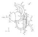
図1は、一部の例による、耳に位置決めされたインイヤーヘッドホン10の図である。ヘッドホン10は、差込式イヤホンまたは他のインイヤー様式のイヤホンとでき、ある種類のヘッドホンを描写している。しかしながら、本発明の概念は、図1に示したヘッドホン10の例に限定されない。したがって、他のヘッドホンの種類が等しく適用できる。ヘッドホン10は、左耳に位置決めするために構成および配置されているが、代替または追加で、例えばここでは他の図において示されている右耳に位置決めするために構成および配置されてもよい。 FIG. 1 is a diagram of an in-
ヘッドホン10は軸Aに沿って中心付けられ得る。ケーブル出口14が、軸Aからずれている軸B、または、軸Aと平行である軸Bに沿って延びているヘッドホン本体16またはその近位の領域に位置決めされている。ケーブル12が、ケーブル出口14から延びるように構成および配置されている。ケーブル12は、ケーブルの一端における音システムまたは第2のヘッドホン(図示せず)と、例えばケーブル出口14におけるといったケーブルの他端におけるヘッドホン10との間で、例えば音響データといった電気信号を交換するために構成および配置され得る。
軸Bに沿うケーブル出口14の場所は、例えば、図1に示すように、ケーブル12がヘッドホン10のケーブル出口14から着用者の襟首に延びるときといった、着用者の耳に位置決めされるとき、ヘッドホン10の差込式イヤホン(図1には示していない)に付与される力を、ヘッドホン10に安定性を与えるように対処および分配することができる。差込式イヤホンの後縁におけるケーブル出口14の場所は、着用者の移動の間であっても耳におけるイヤホンの位置を維持するヘッドホン10(後述されている)の様々な要素に付与される力の分配に変換され、それによって、耳において不安定に着座される差込式イヤホンに伴う不満および/または不快感を低減する。例えば、移動または振動は、既存の差込式イヤホンを排出してしまう可能性がある。ヘッドホン10は、力が代わりに安定性を向上し、関連する用途において、外耳道における封止を向上するように、差込式イヤホンを排出してしまうことになるこれらの力を応用するように構成および配置されている。 The location of the
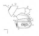
図2は、一部の例による、ヘッドホン10の外観の斜視図である。図3は、図2のヘッドホン10の後面図である。ヘッドホン10は、図1に関して示されて記述されているものと同一または同様であり得る。図2および図3のヘッドホン10は、右耳に位置決めするために構成および配置されているとして示されているが、代替または追加で、例えば図1において示されている左耳に位置決めするために構成および配置されてもよい。 FIG. 2 is a perspective view of the appearance of the
ヘッドホン10の差込式イヤホン26は、選択的なヘッドホン本体16に連結できる。代替で、差込式イヤホン26および選択的な本体16は、例えば共通のプラスチックから成形されるといった、同じ材料から形成できる。 The plug-in
ヘッドホン本体16は、差込式イヤホン26に連結されるケーブル出口接合部28、または、例えば共通の材料から成形されるといった差込式イヤホン26から延びるケーブル出口接合部28を備えている。様々な構成要素が、同じ材料または異なる材料から形成されてもよく、一体に成形または組み立てられてもよい。例えば、ヘッドホン本体16の選択的な電子部品筐体24が、ケーブル出口接合部28に連結されてもよい、または、ケーブル出口接合部28および/または差込式イヤホン26と共通の材料から成形されてもよい。 The
ケーブル出口接合部28は、ケーブル12が延びているケーブル出口14を備えている。ケーブル出口接合部28は、力または重力に関連する力がケーブル12に存在しないときにケーブル12が沿って延びることができる溝などの経路18も備え得る。力が、経路18に正接する方向で、筐体24から離れるようにケーブル12に加えられ得る。ケーブル出口接合部28および選択的な経路18は、ヘッドホン10が着用されるとき、ケーブル出口接合部28から延びているケーブル12が、電子部品筐体24などと接触または他の形で干渉するのを防止するように構成および配置されている。 The cable outlet joint 28 includes a
電子部品筐体24は、ケーブル出口接合部28に連結するように構成され得る。電子部品筐体24は、例えば音を処理するための電子回路といった、ヘッドホン10を動作させることができる回路を備え得る。筐体24は、筐体24におけるマイクロホンに関する回路と伝達するためのマイクロホン開口を備え得る。筐体24は、電子部品筐体24の遠位端にコネクタ15を備え得る。コネクタ15は、電力および/またはデータをヘッドホン10に提供するために、例えばマイクロユニバーサルシリアルバス(USB)装置などの電子装置と連結するためのポートまたはソケットなどを含み得る。筐体24は、例えばスピーカの音量を調節するといった、電子部品筐体24、ケーブル出口接合部、および/または差込式イヤホン26における様々な回路を制御するための、ボタン、スイッチなどの1つまたは複数の回路インターフェース20を備え得る。 The
差込式イヤホン26は、耳において、より具体的には、外耳道の近位の耳の領域において位置決めするように構成および配置された差込式イヤホン筐体に位置決めされるスピーカなどの音響の伝達機構または変換器を備え得る。差込式イヤホン26は、開口を有するノズル22を備えており、それによって、スピーカにおいて生成される音に関する信号が、開口を通じてノズル22から出力され得る。ノズル22は、ケーブル出口接合部28とは差込式イヤホン26の異なる位置にあり、例えば、ノズル22とケーブル出口接合部28とは、差込式イヤホン26における回転の中心の両側にある。ノズル22とケーブル出口接合部28とは、力がケーブル出口接合部28から延びるケーブル12に付与されるとき、力が外耳道においてノズル22および/またはノズルに連結された差込式イヤホン先端30を「固定する」ようにノズル22に付与されるように、互いに対して差込式イヤホン26において位置決めするように構成および配置されている。例えば、ケーブル12の垂れ下がりは重力によって駆動される。差込式イヤホン26、ノズル22、および/または差込式イヤホン先端30の位置決めがある首の後ろは、内耳の特徴によって駆動される。例えば、ケーブル出口接合部28とケーブル12とは、B軸に沿って、または、基軸において示されているY軸に沿って、延びることができる。ここで、ノズル22は、前述のことを達成するために、x-z平面に正接するように構成および配置され得る。 The plug-in
差込式イヤホン先端30は、ノズル22を覆って位置決めされ得る先端本体34を備えている。先端本体34の遠位端31は、例えば円錐形といった、外耳道の近位の耳の領域の内部に嵌まるように構成されている。先端本体34は、柔軟性がある、圧縮性がある、および/またはエラストマである材料を含むことができ、そのため、差込式イヤホン先端30は、(後述されている)力によって外耳道に押し込まれるとき、耳に適合できる。先端本体34の遠位端31は、差込式イヤホン26におけるスピーカなどによって発生される音がノズル22および先端本体開口31を介して外耳道に出力され得るように、ノズル開口と並べられ得る開口を備えている。 The plug-in
先端30は、耳の対耳輪に沿って位置決めするために、および、差込式イヤホン先端30および差込式イヤホン26に対する枢動位置を提供するために構成および配置される保持輪体32を備えており、そのため、輪体32、差込式イヤホン先端30、および差込式イヤホン26は、1つまたは複数の力がヘッドホン10に加えられるとき、枢動位置に対して各々回転する。参照により本明細書において両方とも組み込まれている米国特許第8,249,287号および米国特許出願公開第2013/0230204号を参照されたい。 The
図4は、図2および図3のヘッドホン10の別の斜視図であり、一部の例による、ヘッドホン10が耳に位置決めされるときにヘッドホン10に加えられる力の図である。図5は、図2〜図4のヘッドホン10の下面図であり、一部の例による、ヘッドホン10が耳に位置決めされるときにヘッドホン10に加えられる力の図である。図6は、一部の例による、人の耳に位置決めされた図2〜図5のヘッドホンの図である。 FIG. 4 is another perspective view of the
一部の例による、ヘッドホンケーブル12が第1の位置P1から第2の位置P2に移行するとき、力がヘッドホン10に加えられる。ヘッドホンケーブル12の第1の位置P1は、差込式イヤホン先端30が耳(図示せず)において最初に挿入されるとき、ヘッドホン10の位置であり得る。ヘッドホン10の第2の位置P2は「固定位置」として言及でき、それによって、ケーブル12は、首または肩の上に垂らされ、1つまたは複数の力が、耳においてヘッドホン10を安定化するために、ヘッドホン10の異なる要素に加えられる。 According to some examples, a force is applied to the
前述のように、ケーブル出口14は、差込式イヤホン26の後縁に隣接するケーブル出口接合部28の領域に位置決めされ、そのため差込式イヤホン26に対して中心から外れている。ここで、ケーブル出口接合部28は、固定位置P2において差込式イヤホン26および/または差込式イヤホン先端30を耳に着座するための力を分配できる。したがって、ケーブル出口14から延びるケーブル12の移動は、差込式イヤホン26またはヘッドホン本体16によって邪魔されない。 As described above, the
第1の位置P1において、ケーブル12は、例えば、鉛直または鉛直に近い方向において軸Bに沿って、ならびに、差込式イヤホン26および/またはヘッドホン本体16が延びる中心軸Aと平行または平行の近くで、第1の方向においてケーブル出口14から延び得る。第2の位置P2において、ケーブルは、第1の方向に対して正接である第2の方向に延びる。 In the first position P1, the
ケーブル12は、水平成分Fxおよび鉛直成分Fyを含む第1の力F1に曝され得る。ケーブル12が、例えば首の後ろの周りに垂らされ、第2の位置P2にあるとき、第1の力F1はx軸から角度θにおいて作用する。例えば、ケーブル12は、首の後ろ(図示せず)に向かって後方下向きに引っ張られる。 The
このようにしてケーブルに加えられる第1の力F1に応答して、トルクTが差込式イヤホン26および/または選択的な差込式イヤホン先端30に付与され得る。より具体的には、差込式イヤホン26が耳において位置決めされた後、トルクTは、差込式イヤホン26がヘッドホン10に対して中心付けられている枢動位置Zの周りに、例えば後ろから見たときに右の差込式イヤホンの時計回り方向において、付与され得る。ノズル22および/またはノズル22を覆って位置決めされた差込式イヤホン先端30は、回転力が周りで回転するZ軸(図4が基軸で示されている頁から延び出す)に正接している軸に沿って差込式イヤホン26から延び得る。トルクTは、例えば螺旋経路に沿って、外耳道の方向D1においてノズル22および先端本体31を駆動し、それによって外耳道において遠位端31を固定する同じトルクであり得る。トルクTは、対珠の下で、本体31を駆動する同じトルクでもあり得る。そのようにすることで、支配的な力Fyは差込式イヤホン26の中心の周りにトルクTを作り出し、それによって、トルクの大きさは、差込式イヤホン26の中心軸Aへの距離に依存し得る。したがって、外耳道と対珠の下の切り欠きとは、差込式イヤホン26および先端30についての基準を形成している。 In response to the first force F1 applied to the cable in this manner, torque T may be applied to the plug-in
また、保持輪体32は、耳の対耳輪に沿って時計回り方向D2において回転して、保持輪体32の外側脚37を対耳輪の下に着座させ、これは、遠位端31が外耳道に入るのに寄与できる。また、先端本体34は方向D3において移動し、それによってトルクが加えられ、これは、先端本体34および/または外側脚37の少なくとも一部を、耳の対珠の下の固定位置に置く。輪体32の内側脚38は対耳輪の上部において力を加えることができ、そのため、輪体32は対耳輪の下で固定する。輪体32は、柔軟性があり、複数の耳の内部の大きさに適合するまで、平面の内外に移動でき、渦を巻くことができる。 The retaining
したがって、ヘッドホン10の動作の間、ヘッドホン10は耳において安定して位置決めでき、これは、使用者の体が小さい動作を経験するスポーツ行事などの活動の間に有益である。このような動作は、ケーブルが、このような体の動作の間であっても、外耳道に向かって差込式イヤホン26に力を付与する形で角度付けられるため、差込式イヤホン先端30を外耳道入口に押し付けて維持できる。 Thus, during operation of the
また、差込式イヤホン先端30が前述の力に応答して外耳道に駆り立てられるとき、差込式イヤホン先端30、または、差込式イヤホン先端のない柔軟な構成を有するノズルを形成する柔軟な材料は、外耳道入口に対して、封止接合部、または、シールもしくはプラグを提供でき、耳におけるヘッドホン10のさらなる安定した位置決めを提供できる。 Also, when the plug-in
ヘッドホン10は、例えば、ケーブル12を反対方向で引っ張ることに応答して差込式イヤホン26を耳から排出することで、耳において取り外しできる。これは、一部の例では、例えばトルクTを反対方向において加えることによってといった、図4に記述されている1つまたは複数の力の方向を反転することによって、達成できる。それによって、ノズル22は、方向D1と反対の方向、つまり、外耳道から離れる方向において、例えば螺旋経路に沿って移動し、それによって差込式イヤホン先端30の遠位端31を外耳道から分離する。 The
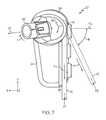
図7は、ヘッドホン10'の別の斜視図であり、他の例による、ヘッドホン10'が耳に位置決めされるときにヘッドホン10'に加えられる力の図である。ヘッドホン10'は、ヘッドホン10'が差込式イヤホン先端を備えていないことを除いて、図2〜図6において記述したヘッドホン10と同様であり得る。代わりに、ヘッドホン10'は、人の耳の外耳道に位置決めされるノズル42を備えている。ノズル42は、差込式イヤホン先端30が覆うように位置決めされるヘッドホン10のノズル22と同様の構成または異なる構成を有することができる。例えば、ノズル42は柔軟な材料から形成でき、ヘッドホン10'が外耳道に位置決めされ、ケーブル12が、ここで記述されている1つまたは複数の力を付与する位置で関節接合されるとき、外耳道表面に従順に適合する圧縮可能な表面を提供する。 FIG. 7 is another perspective view of the
ケーブル出口14は、差込式イヤホン26の後縁に隣接するケーブル出口接合部28の領域に位置決めされ、そのため差込式イヤホン26に対して中心から外れている。ここで、ケーブル出口接合部28は、固定位置P2において差込式イヤホン26および/またはノズル42を耳に着座するための力を分配できる。 The
一部の例による、ヘッドホンケーブル12が第1の位置P1から第2の位置P2に移行するとき、1つまたは複数の力がヘッドホン10'に加えられる。第2の位置P2において、1つまたは複数の力は、耳においてヘッドホン10'を安定化するために、ヘッドホン10'の異なる要素に加えられる。 According to some examples, when the
第1の位置P1において、ケーブル12は、例えば、鉛直または鉛直に近い方向において、ならびに、差込式イヤホン26および/またはヘッドホン本体16が延びる中心軸と平行または平行の近くで、第1の方向においてケーブル出口14から延び得る。第2の位置P2において、ケーブルは、第1の方向に対して正接である第2の方向に延びる。 In the first position P1, the
ケーブル12は、水平成分Fxおよび鉛直成分Fyを含む第1の力F1に曝され得る。ケーブル12が、例えば首の後ろの周りに垂らされ、第2の位置P2にあるとき、第1の力F1はx軸から角度θにおいて作用する。例えば、ケーブル12は、首の後ろ(図示せず)に向かって後方下向きに引っ張られる。 The
このようにしてケーブルに加えられる第1の力F1に応答して、トルクTが差込式イヤホン26に付与され得る。より具体的には、差込式イヤホン26が耳において位置決めされた後、トルクTは、差込式イヤホン26がヘッドホン10に対して中心付けられている枢動位置Zの周りに、例えば時計回り方向において、付与され得る。ノズル22は、トルクTが周りで回転するZ軸(図7が示されている頁から延び出す)に正接している軸に沿って差込式イヤホン26から延び得る。付与されるトルクTは、例えば螺旋経路に沿って、外耳道の方向D1においてノズル42を駆動し、それによって外耳道においてノズル42を固定できる。 In this way, torque T can be applied to the plug-in
いくつかの実施が記述されてきた。それでもなお、前述の記述が、特許請求の範囲よって定められる範囲を図示するように意図されており、限定するように意図されていないことは、理解されるものである。 Several implementations have been described. Nevertheless, it is to be understood that the foregoing description is intended to illustrate the scope defined by the claims, and is not intended to be limiting.
10 インイヤーヘッドホン
10' ヘッドホン
12 ケーブル
14 ケーブル出口
15 コネクタ
16 ヘッドホン本体
18 経路
20 回路インターフェース
22 ノズル
24 電子部品筐体
26 差込式イヤホン
28 ケーブル出口接合部
30 差込式イヤホン先端
31 遠位端、先端本体開口
32 保持輪体
34 先端本体
37 外側脚
38 内側脚
42 ノズル
A 軸
B 軸
D1 外耳道の方向
D2 時計回り方向
D3 方向
F1 第1の力
Fx 水平成分
Fy 鉛直成分
P1 第1の位置
P2 第2の位置
T トルク
Z 枢動位置
θ 角度10 In-ear headphones
10 'headphones
12 Cable
14 Cable outlet
15 Connector
16 Headphone body
18 routes
20 Circuit interface
22 nozzles
24 Electronic component housing
26 Plug-in type earphone
28 Cable outlet joint
30 Plug-in type earphone tip
31 Distal end, tip body opening
32 retaining ring
34 Tip body
37 Outer legs
38 Inner leg
42 nozzles
A axis
B axis
D1 Direction of the ear canal
D2 clockwise direction
D3 direction
F1 first force
Fx horizontal component
Fy vertical component
P1 1st position
P2 2nd position
T torque
Z pivot position θ angle
Claims (20)
Translated fromJapanese前記耳の外耳道において位置決めするために、および、前記耳の前記外耳道における音響出力を方向付けるために、前記差込式イヤホン本体から延びるノズルと、
前記差込式イヤホン本体の縁の近位の領域に沿って前記第1の方向に延びる第2の軸に沿う前記差込式イヤホン本体の縁におけるケーブル出口接合部であって、前記第2の軸が前記第1の軸からずれている、ケーブル出口接合部と、
前記差込式イヤホン本体の前記縁における前記ケーブル出口接合部から延びるケーブルであって、前記ケーブル出口接合部が、前記第1の軸から離れると共に前記第2の軸に正接する方向でケーブルに付与される力に応答して、前記外耳道の方向で前記ノズルに力を付与するように構成および配置される、ケーブルと
を備えるインイヤーヘッドホン。A plug-in earphone body configured and arranged for positioning in a wearer's ear and extending along a first axis in a first direction;
A nozzle extending from the plug-in earphone body for positioning in the ear canal of the ear and for directing sound output in the ear canal of the ear;
A cable outlet joint at an edge of the plug-in earphone body along a second axis extending in the first direction along a region proximal to the edge of the plug-in earphone body, the second A cable outlet joint, the axis of which is offset from the first axis;
A cable extending from the cable outlet joint at the edge of the plug-in earphone body, the cable outlet joint being applied to the cable in a direction away from the first axis and tangent to the second axis An in-ear headphone comprising: a cable configured and arranged to apply a force to the nozzle in the direction of the ear canal in response to the applied force.
前記筐体において位置決めされる複数の電子構成要素であって、前記ケーブルの移動に応答して前記ケーブルに付与される前記力が前記筐体によって制限されない、複数の電子構成要素と
をさらに備える、請求項1に記載のインイヤーヘッドホン。A housing coupled to the cable outlet joint,
A plurality of electronic components positioned in the housing, further comprising a plurality of electronic components in which the force applied to the cable in response to movement of the cable is not limited by the housing; The in-ear headphone according to claim 1.
前記ケーブルが、前記ケーブルに加えられ得る前記力に応答して前記経路に正接する方向で延びる、請求項1に記載のインイヤーヘッドホン。Further comprising a path extending from the cable outlet along the second axis;
The in-ear headphone of claim 1, wherein the cable extends in a direction tangential to the path in response to the force that can be applied to the cable.
前記差込式イヤホン本体に連結され、外耳道において位置決めするための円錐形遠位端を備える差込式イヤホン先端と、
前記差込式イヤホン本体の縁の近位の領域に沿って前記第1の方向に延びる第2の軸に沿う前記差込式イヤホン本体の縁におけるケーブル出口接合部であって、前記第2の軸が前記第1の軸からずれている、ケーブル出口接合部と、
前記差込式イヤホン本体の前記縁における前記ケーブル出口接合部から延びるケーブルであって、前記ケーブル出口接合部が、ケーブルに付与される力に応答して、前記外耳道において前記差込式イヤホン先端を固定するように構成および配置される、ケーブルと
を備えるインイヤーヘッドホン。A plug-in earphone body configured and arranged for positioning in a wearer's ear and positioned along a first axis extending in a first direction;
A plug-in earphone tip connected to the plug-in earphone body and having a conical distal end for positioning in the ear canal;
A cable outlet joint at an edge of the plug-in earphone body along a second axis extending in the first direction along a region proximal to the edge of the plug-in earphone body, the second A cable outlet joint, the axis of which is offset from the first axis;
A cable extending from the cable outlet joint at the edge of the plug-in earphone body, the cable outlet joint responding to a force applied to the cable, the tip of the plug-in earphone in the ear canal In-ear headphones comprising: a cable configured and arranged to be fixed.
前記ヘッドホンの差込式イヤホンのノズルの少なくとも一部分を、前記耳における外耳道において挿入するステップと、
第1の方向で延びる第1の軸に沿って差込式イヤホン本体を位置決めするステップと、
ケーブルを、前記差込式イヤホン本体の縁におけるケーブル出口接合部から、前記第1の方向において、前記第1の軸からずれている第2の軸に沿って位置決めするステップと、
前記第1の軸から離れると共に前記第2の軸に正接する方向で前記ケーブルに力を付与するステップと、
前記差込式イヤホン本体の前記縁における前記ケーブル出口接合部から延びる前記ケーブルに付与される前記力に応答して、前記外耳道の方向で前記ノズルに力を付与するステップと
を含む方法。A method for positioning and holding headphones in an ear,
Inserting at least a portion of the headphone plug-in earphone nozzle in the ear canal of the ear;
Positioning the plug-in earphone body along a first axis extending in a first direction;
Positioning the cable along a second axis that is offset from the first axis in the first direction from the cable outlet joint at the edge of the plug-in earphone body;
Applying a force to the cable in a direction away from the first axis and tangent to the second axis;
Applying a force to the nozzle in the direction of the ear canal in response to the force applied to the cable extending from the cable exit junction at the edge of the plug-in earphone body.
前記ケーブルに前記力を付与することに応答してトルクを付与するステップであって、前記トルクは、前記差込式イヤホン先端の遠位端を前記耳の前記外耳道に駆動し、前記保持輪体が前記耳の対耳輪に沿う方向で移動するように前記保持輪体を駆動し、前記耳の対珠において前記差込式イヤホン先端を位置決めして、安定して位置決めするために前記差込式イヤホン先端を駆動する、ステップと
をさらに含む、請求項17に記載の方法。Connecting a tip of a plug-in type earphone provided with a holding ring body at the nozzle of the plug-in type earphone main body;
Applying torque to the cable in response to applying the force, the torque driving a distal end of the plug-in earphone tip to the ear canal of the ear, and the retaining ring Driving the holding ring body so as to move in a direction along the ear-to-ear ring, and positioning the tip of the plug-in earphone in the ear-to-ear bead for stable positioning. The method of claim 17, further comprising: driving the earphone tip.
Applications Claiming Priority (3)
| Application Number | Priority Date | Filing Date | Title |
|---|---|---|---|
| US14/294,694 | 2014-06-03 | ||
| US14/294,694US9854345B2 (en) | 2014-06-03 | 2014-06-03 | In-ear headphone with cable exit positioned for improved stability |
| PCT/US2015/033525WO2015187552A1 (en) | 2014-06-03 | 2015-06-01 | In-ear headphone with cable exit positioned for improved stability |
Publications (2)
| Publication Number | Publication Date |
|---|---|
| JP2017517219Atrue JP2017517219A (en) | 2017-06-22 |
| JP6374534B2 JP6374534B2 (en) | 2018-08-15 |
Family
ID=53373665
Family Applications (1)
| Application Number | Title | Priority Date | Filing Date |
|---|---|---|---|
| JP2016571135AExpired - Fee RelatedJP6374534B2 (en) | 2014-06-03 | 2015-06-01 | In-ear headphones with cable outlets positioned for improved stability |
Country Status (5)
| Country | Link |
|---|---|
| US (1) | US9854345B2 (en) |
| EP (1) | EP3152918B1 (en) |
| JP (1) | JP6374534B2 (en) |
| CN (1) | CN106465000B (en) |
| WO (1) | WO2015187552A1 (en) |
Families Citing this family (37)
| Publication number | Priority date | Publication date | Assignee | Title |
|---|---|---|---|---|
| US10856068B2 (en) | 2015-09-16 | 2020-12-01 | Apple Inc. | Earbuds |
| USD801302S1 (en)* | 2016-08-03 | 2017-10-31 | Shenzhen Joway Power Supply Co, Ltd | Wireless earphone |
| US10051388B2 (en) | 2016-09-21 | 2018-08-14 | Starkey Laboratories, Inc. | Radio frequency antenna for an in-the-ear hearing device |
| US10462549B2 (en)* | 2016-12-09 | 2019-10-29 | Kingston Technology Corp. | Headphones with an ergonomic cushion and an ergonomic cushion thereof |
| USD860172S1 (en) | 2017-02-14 | 2019-09-17 | Spigen Korea Co., Ltd. | Earhook for earpieces |
| US10362384B2 (en) | 2017-04-19 | 2019-07-23 | Spigen Korea Co., Ltd. | Earphone cover |
| USD870079S1 (en) | 2017-05-12 | 2019-12-17 | Spigen Korea Co., Ltd. | Earhook for earpieces |
| US10397713B2 (en)* | 2017-08-30 | 2019-08-27 | Gn Hearing A/S | Earpiece for a hearing device and a hearing device |
| US11307661B2 (en) | 2017-09-25 | 2022-04-19 | Apple Inc. | Electronic device with actuators for producing haptic and audio output along a device housing |
| US10212507B1 (en) | 2018-03-06 | 2019-02-19 | Bose Corporation | Headphone |
| US10516929B2 (en)* | 2018-03-06 | 2019-12-24 | Bose Corporation | Audio device |
| US10873798B1 (en) | 2018-06-11 | 2020-12-22 | Apple Inc. | Detecting through-body inputs at a wearable audio device |
| US10757491B1 (en) | 2018-06-11 | 2020-08-25 | Apple Inc. | Wearable interactive audio device |
| US11334032B2 (en) | 2018-08-30 | 2022-05-17 | Apple Inc. | Electronic watch with barometric vent |
| US11561144B1 (en) | 2018-09-27 | 2023-01-24 | Apple Inc. | Wearable electronic device with fluid-based pressure sensing |
| US11102563B2 (en) | 2018-09-28 | 2021-08-24 | Apple Inc. | Attachment mechanism for eartips |
| US10993009B2 (en) | 2019-01-07 | 2021-04-27 | Bose Corporation | Earphone |
| US10827247B2 (en) | 2019-01-07 | 2020-11-03 | Bose Corporation | Earphone |
| US10932027B2 (en) | 2019-03-03 | 2021-02-23 | Bose Corporation | Wearable audio device with docking or parking magnet having different magnetic flux on opposing sides of the magnet |
| US11067644B2 (en)* | 2019-03-14 | 2021-07-20 | Bose Corporation | Wearable audio device with nulling magnet |
| US11061081B2 (en) | 2019-03-21 | 2021-07-13 | Bose Corporation | Wearable audio device |
| US11076214B2 (en) | 2019-03-21 | 2021-07-27 | Bose Corporation | Wearable audio device |
| CN114399012B (en) | 2019-04-17 | 2024-08-06 | 苹果公司 | Wireless locatable tag |
| US11272282B2 (en) | 2019-05-30 | 2022-03-08 | Bose Corporation | Wearable audio device |
| US11223895B2 (en) | 2020-03-24 | 2022-01-11 | Bose Corporation | Wearable audio device with counter-bore port feature |
| EP4552343A1 (en) | 2020-05-25 | 2025-05-14 | Bose Corporation | Wearable audio device placement detection |
| US11202137B1 (en) | 2020-05-25 | 2021-12-14 | Bose Corporation | Wearable audio device placement detection |
| USD961552S1 (en) | 2020-05-27 | 2022-08-23 | Amazon Technologies, Inc. | Earbud tip |
| US11350204B2 (en) | 2020-08-14 | 2022-05-31 | Bose Corporation | Wearable audio device feedforward instability detection |
| US11606637B2 (en) | 2021-02-26 | 2023-03-14 | Apple Inc. | Wireless listening device |
| US12256032B2 (en) | 2021-03-02 | 2025-03-18 | Apple Inc. | Handheld electronic device |
| US20240179462A1 (en) | 2021-04-06 | 2024-05-30 | Bose Corporation | Audio device with electrostatic discharge protection |
| USD954028S1 (en)* | 2021-04-26 | 2022-06-07 | Shaozheng Gao | Earphone cover |
| USD993940S1 (en)* | 2021-05-18 | 2023-08-01 | Dongguan Edifier Technology Co., Ltd. | Pair of wingtips for earphones |
| US11638081B2 (en) | 2021-09-04 | 2023-04-25 | Bose Corporation | Earphone port |
| USD962204S1 (en)* | 2021-09-10 | 2022-08-30 | Class and Culture LLC | Pair of tapered earbud covers |
| US12160698B2 (en)* | 2021-09-22 | 2024-12-03 | Apple Inc. | Audio device with wingtip anchor |
Citations (10)
| Publication number | Priority date | Publication date | Assignee | Title |
|---|---|---|---|---|
| JPH0965475A (en)* | 1995-08-23 | 1997-03-07 | Sony Corp | Electroacoustic transducer and ear shell mount body for electroacoustic transducer |
| US20060239447A1 (en)* | 2005-04-26 | 2006-10-26 | Shure Acquisition Holdings, Inc. | Earphone with selectable cable positioning |
| US20070154050A1 (en)* | 2005-12-29 | 2007-07-05 | Samsung Electronics Co., Ltd | Earphone having variable duct unit |
| US20080310666A1 (en)* | 2007-06-13 | 2008-12-18 | Eric John Wengreen | Headphone Adaptation and Positioning Device |
| JP2011061725A (en)* | 2009-09-14 | 2011-03-24 | Audio Technica Corp | Canal-type earphone |
| US20120027242A1 (en)* | 2010-07-29 | 2012-02-02 | Microsoft Corporation | Adjustable earphone and earphone set |
| US20120087534A1 (en)* | 2008-05-19 | 2012-04-12 | Koss Corporation | Adjustable, dual speaker element in-ear phone |
| US8249287B2 (en)* | 2010-08-16 | 2012-08-21 | Bose Corporation | Earpiece positioning and retaining |
| JP2014045321A (en)* | 2012-08-27 | 2014-03-13 | Jvc Kenwood Corp | Headphone |
| WO2014041604A1 (en)* | 2012-09-11 | 2014-03-20 | パイオニア株式会社 | Earphone unit |
Family Cites Families (20)
| Publication number | Priority date | Publication date | Assignee | Title |
|---|---|---|---|---|
| US3548118A (en)* | 1969-07-03 | 1970-12-15 | Pacific Plantronics Inc | Self-supporting headset |
| DE69318466T2 (en)* | 1992-03-30 | 1998-09-03 | Sony Corp | headphone |
| US5659156A (en)* | 1995-02-03 | 1997-08-19 | Jabra Corporation | Earmolds for two-way communications devices |
| US5761298A (en)* | 1996-05-31 | 1998-06-02 | Plantronics, Inc. | Communications headset with universally adaptable receiver and voice transmitter |
| JP3838072B2 (en)* | 2001-10-31 | 2006-10-25 | ソニー株式会社 | headphone |
| US6760459B2 (en)* | 2002-02-15 | 2004-07-06 | Youngbo Engineering, Inc. | Method for securing a headset |
| US7536008B2 (en)* | 2002-03-02 | 2009-05-19 | Logitech Europe S.A. | Antihelix-conforming ear-mount for personal audio-set |
| US6688421B2 (en)* | 2002-04-18 | 2004-02-10 | Jabra Corporation | Earmold for improved retention of coupled device |
| US20080144877A1 (en)* | 2004-07-01 | 2008-06-19 | Plantronics, Inc. | Antihelix stabilizer with easy donning action for wearable audio device |
| WO2006104981A2 (en)* | 2005-03-28 | 2006-10-05 | Sound Id | Non-occluding ear module for a personal sound system |
| TWI282246B (en)* | 2005-11-09 | 2007-06-01 | Cotron Corp | In-ear type earphone having an ear hanger |
| KR100757462B1 (en)* | 2006-07-14 | 2007-09-11 | 삼성전자주식회사 | earphone |
| JP4946538B2 (en)* | 2007-03-13 | 2012-06-06 | ソニー株式会社 | Headphone device |
| DK176704B1 (en) | 2007-05-31 | 2009-03-23 | Gn Netcom As | Headphone with alternating earplug |
| US20090110227A1 (en)* | 2007-10-31 | 2009-04-30 | Allen Lamont Prince | Earphone earbud stabilizer |
| US20090285434A1 (en) | 2008-05-13 | 2009-11-19 | Jason Martin Williams | Earhook and earbud headset |
| US8249286B2 (en)* | 2009-08-24 | 2012-08-21 | Koss Corporation | Interconnecting earphones |
| US8311253B2 (en)* | 2010-08-16 | 2012-11-13 | Bose Corporation | Earpiece positioning and retaining |
| US8737669B2 (en) | 2011-07-28 | 2014-05-27 | Bose Corporation | Earpiece passive noise attenuating |
| US20140211977A1 (en)* | 2012-11-16 | 2014-07-31 | Judd Armstrong | Over/under dual-fit wearing option earphones |
- 2014
- 2014-06-03USUS14/294,694patent/US9854345B2/ennot_activeExpired - Fee Related
- 2015
- 2015-06-01EPEP15728360.7Apatent/EP3152918B1/ennot_activeNot-in-force
- 2015-06-01CNCN201580030288.XApatent/CN106465000B/ennot_activeExpired - Fee Related
- 2015-06-01JPJP2016571135Apatent/JP6374534B2/ennot_activeExpired - Fee Related
- 2015-06-01WOPCT/US2015/033525patent/WO2015187552A1/enactiveApplication Filing
Patent Citations (10)
| Publication number | Priority date | Publication date | Assignee | Title |
|---|---|---|---|---|
| JPH0965475A (en)* | 1995-08-23 | 1997-03-07 | Sony Corp | Electroacoustic transducer and ear shell mount body for electroacoustic transducer |
| US20060239447A1 (en)* | 2005-04-26 | 2006-10-26 | Shure Acquisition Holdings, Inc. | Earphone with selectable cable positioning |
| US20070154050A1 (en)* | 2005-12-29 | 2007-07-05 | Samsung Electronics Co., Ltd | Earphone having variable duct unit |
| US20080310666A1 (en)* | 2007-06-13 | 2008-12-18 | Eric John Wengreen | Headphone Adaptation and Positioning Device |
| US20120087534A1 (en)* | 2008-05-19 | 2012-04-12 | Koss Corporation | Adjustable, dual speaker element in-ear phone |
| JP2011061725A (en)* | 2009-09-14 | 2011-03-24 | Audio Technica Corp | Canal-type earphone |
| US20120027242A1 (en)* | 2010-07-29 | 2012-02-02 | Microsoft Corporation | Adjustable earphone and earphone set |
| US8249287B2 (en)* | 2010-08-16 | 2012-08-21 | Bose Corporation | Earpiece positioning and retaining |
| JP2014045321A (en)* | 2012-08-27 | 2014-03-13 | Jvc Kenwood Corp | Headphone |
| WO2014041604A1 (en)* | 2012-09-11 | 2014-03-20 | パイオニア株式会社 | Earphone unit |
Also Published As
| Publication number | Publication date |
|---|---|
| WO2015187552A1 (en) | 2015-12-10 |
| JP6374534B2 (en) | 2018-08-15 |
| EP3152918A1 (en) | 2017-04-12 |
| EP3152918B1 (en) | 2018-08-15 |
| CN106465000A (en) | 2017-02-22 |
| US20150350764A1 (en) | 2015-12-03 |
| CN106465000B (en) | 2019-05-10 |
| US9854345B2 (en) | 2017-12-26 |
Similar Documents
| Publication | Publication Date | Title |
|---|---|---|
| JP6374534B2 (en) | In-ear headphones with cable outlets positioned for improved stability | |
| USD808934S1 (en) | Earbud | |
| CN109076277B (en) | Headset assembly having wingtips for securing to a user | |
| CN212231703U (en) | ear-like structure | |
| US7784583B1 (en) | Deep insertion vented earpiece system | |
| US10993016B2 (en) | Earphone with modular earfin and earhook fittings | |
| JP4289376B2 (en) | headset | |
| TWM544746U (en) | Freely adjustable ergonomic bone conduction earphone holder and bone conduction earphone | |
| KR20190117776A (en) | Strap arm on head wearing display with integrated audio port | |
| US8333260B1 (en) | Deep insertion vented earpiece system | |
| JP7288627B2 (en) | earphones and headphones | |
| JP2016063276A (en) | Cartilage conduction hearing aid, cartilage conduction speaker cover and cartilage conduction speaker | |
| CN114586373B (en) | earphone | |
| JP5281436B2 (en) | earphone | |
| JP6427701B1 (en) | Ear mold, earphone, and cartilage conduction hearing aid | |
| KR101723761B1 (en) | Behind the ear hearing aid | |
| JP5795359B2 (en) | earphone | |
| JP6911769B2 (en) | Acoustic output device | |
| KR101485005B1 (en) | Eartip capable of allowing inflow of sound from outside and Earphone having the same | |
| JP6468267B2 (en) | Earphone, band member used therefor, and method of using earphone | |
| CN206506654U (en) | Headphone body and earphone | |
| KR101524764B1 (en) | Holder for earring type earphone | |
| KR102315063B1 (en) | Semi-canal type wireless earset | |
| CN206181322U (en) | In -ear earphone structure | |
| CN210807587U (en) | A head-mounted two-channel earphone |
Legal Events
| Date | Code | Title | Description |
|---|---|---|---|
| A621 | Written request for application examination | Free format text:JAPANESE INTERMEDIATE CODE: A621 Effective date:20170104 | |
| A131 | Notification of reasons for refusal | Free format text:JAPANESE INTERMEDIATE CODE: A131 Effective date:20171106 | |
| A521 | Request for written amendment filed | Free format text:JAPANESE INTERMEDIATE CODE: A523 Effective date:20180205 | |
| TRDD | Decision of grant or rejection written | ||
| A01 | Written decision to grant a patent or to grant a registration (utility model) | Free format text:JAPANESE INTERMEDIATE CODE: A01 Effective date:20180625 | |
| A61 | First payment of annual fees (during grant procedure) | Free format text:JAPANESE INTERMEDIATE CODE: A61 Effective date:20180719 | |
| R150 | Certificate of patent or registration of utility model | Ref document number:6374534 Country of ref document:JP Free format text:JAPANESE INTERMEDIATE CODE: R150 | |
| LAPS | Cancellation because of no payment of annual fees |