JP2017516381A - Congestion control scheme - Google Patents
Congestion control schemeDownload PDFInfo
- Publication number
- JP2017516381A JP2017516381AJP2016561727AJP2016561727AJP2017516381AJP 2017516381 AJP2017516381 AJP 2017516381AJP 2016561727 AJP2016561727 AJP 2016561727AJP 2016561727 AJP2016561727 AJP 2016561727AJP 2017516381 AJP2017516381 AJP 2017516381A
- Authority
- JP
- Japan
- Prior art keywords
- resource
- region
- signal quality
- congestion level
- network congestion
- Prior art date
- Legal status (The legal status is an assumption and is not a legal conclusion. Google has not performed a legal analysis and makes no representation as to the accuracy of the status listed.)
- Pending
Links
Images


Classifications
- H—ELECTRICITY
- H04—ELECTRIC COMMUNICATION TECHNIQUE
- H04W—WIRELESS COMMUNICATION NETWORKS
- H04W28/00—Network traffic management; Network resource management
- H04W28/02—Traffic management, e.g. flow control or congestion control
- H04W28/0289—Congestion control
- H—ELECTRICITY
- H04—ELECTRIC COMMUNICATION TECHNIQUE
- H04L—TRANSMISSION OF DIGITAL INFORMATION, e.g. TELEGRAPHIC COMMUNICATION
- H04L47/00—Traffic control in data switching networks
- H04L47/10—Flow control; Congestion control
- H04L47/11—Identifying congestion
- H—ELECTRICITY
- H04—ELECTRIC COMMUNICATION TECHNIQUE
- H04W—WIRELESS COMMUNICATION NETWORKS
- H04W28/00—Network traffic management; Network resource management
- H04W28/02—Traffic management, e.g. flow control or congestion control
- H04W28/0215—Traffic management, e.g. flow control or congestion control based on user or device properties, e.g. MTC-capable devices
- H—ELECTRICITY
- H04—ELECTRIC COMMUNICATION TECHNIQUE
- H04W—WIRELESS COMMUNICATION NETWORKS
- H04W4/00—Services specially adapted for wireless communication networks; Facilities therefor
- H04W4/70—Services for machine-to-machine communication [M2M] or machine type communication [MTC]
Landscapes
- Engineering & Computer Science (AREA)
- Computer Networks & Wireless Communication (AREA)
- Signal Processing (AREA)
- Mobile Radio Communication Systems (AREA)
- Data Exchanges In Wide-Area Networks (AREA)
Abstract
Translated fromJapaneseDescription
Translated fromJapanese[0001]本願は、2014年4月10日に出願された「CONGESTION CONTROL SCHEME」と題された米国特許出願第14/250,031号の利益を主張し、それは、その全体が本明細書に参照によって明確に組み込まれる。 [0001] This application claims the benefit of US patent application Ser. No. 14 / 250,031, entitled “CONGESTION CONTROL SCHEME” filed Apr. 10, 2014, which is hereby incorporated by reference herein in its entirety. Specifically incorporated by reference.
[0002]本開示は一般に、通信システムに関し、より具体的には、ネットワークデバイス間で輻輳を制御することに関する。 [0002] The present disclosure relates generally to communication systems, and more specifically to controlling congestion between network devices.
[0003]ワイヤレス通信システムは、電話通信、映像、データ、メッセージング、およびブロードキャストのような様々な電気通信サービスを提供するために広く展開されている。典型的なワイヤレス通信システムは、利用可能なシステムリソース(例えば、帯域幅、送信電力)を共有することによって複数のユーザとの通信をサポートすることが可能な多元接続技術を用いうる。そのような多元接続技術の例は、符号分割多元接続(CDMA)システム、時分割多元接続(TDMA)システム、周波数分割多元接続(FDMA)システム、直交周波数分割多元接続(OFDMA)システム、シングルキャリア周波数分割多元接続(SC−FDMA)システム、および時分割同期符号分割多元接続(TD−SCDMA)システムを含む。 [0003] Wireless communication systems are widely deployed to provide various telecommunication services such as telephony, video, data, messaging, and broadcast. A typical wireless communication system may employ multiple access technologies that can support communication with multiple users by sharing available system resources (eg, bandwidth, transmit power). Examples of such multiple access techniques are code division multiple access (CDMA) systems, time division multiple access (TDMA) systems, frequency division multiple access (FDMA) systems, orthogonal frequency division multiple access (OFDMA) systems, single carrier frequency. Division multiple access (SC-FDMA) systems, and time division synchronous code division multiple access (TD-SCDMA) systems.
[0004]これらの多元接続技術は、異なるワイヤレスデバイスが、都市、国家、地域、さらには地球規模で通信することを可能にする共通プロトコルを提供するために様々な電気通信規格において採用されてきた。台頭してきた電気通信規格の例は、ロングタームエボリューション(LTE(登録商標))である。LTEは、第3世代パートナーシッププロジェクト(3GPP(登録商標))によって公表されたユニバーサルモバイル電気通信システム(UMTS)のモバイル規格の拡張セットである。LTEは、スペクトル効率を改善すること、コストを下げること、サービスを改善すること、新たなスペクトルを利用すること、およびダウンリンク(DL)上ではOFDMAを、アップリンク(UL)上ではSC−FDMAを、そして多入力多出力(MIMO)アンテナ技術を使用して、他のオープン規格とより良く統合することによって、モバイルブロードバンドインターネットアクセスをより良くサポートするように設計される。しかしながら、モバイルブロードバンドアクセスに対する需要が増加し続けるにつれて、LTE技術における更なる改善の必要性が存在する。好ましくは、これらの改善は、他の多元接続技術およびこれらの技術を用いる電気通信規格に適用可能であるべきである。 [0004] These multiple access technologies have been adopted in various telecommunication standards to provide a common protocol that allows different wireless devices to communicate in urban, national, regional and even global scales. . An example of an emerging telecommunication standard is Long Term Evolution (LTE (registered trademark)). LTE is an extended set of universal mobile telecommunications system (UMTS) mobile standards published by the 3rd Generation Partnership Project (3GPP®). LTE improves spectrum efficiency, lowers costs, improves service, utilizes new spectrum, and OFDMA on the downlink (DL) and SC-FDMA on the uplink (UL). And better integration with other open standards using multiple-input multiple-output (MIMO) antenna technology is designed to better support mobile broadband Internet access. However, as the demand for mobile broadband access continues to increase, there is a need for further improvements in LTE technology. Preferably, these improvements should be applicable to other multiple access technologies and telecommunications standards using these technologies.
[0005]本開示のある態様において、方法、コンピュータプログラム製品、および装置が提供される。装置は、マシンタイプ通信(MTC:machine type communication)デバイスであり、リソースブロックの少なくとも2つの領域中でのそれぞれの信号品質を測定し、それぞれの信号品質を互いに比較し、比較に基づいてネットワーク輻輳レベルを決定し、ネットワーク輻輳レベルに基づいて、少なくとも2つの領域中にそれぞれ含まれたリソースを使用するかどうかを決めるように構成されうる。 [0005] In certain aspects of the present disclosure, methods, computer program products, and apparatus are provided. The apparatus is a machine type communication (MTC) device that measures respective signal qualities in at least two regions of a resource block, compares the respective signal qualities with each other, and based on the comparison, network congestion The level may be determined and configured to determine whether to use resources respectively included in the at least two regions based on the network congestion level.
[0006]別の態様において、装置は、UEであり、リソースブロックの少なくとも2つの領域中でのそれぞれの信号品質を測定し、それぞれの信号品質を互いに比較し、比較に基づいてネットワーク輻輳レベルを決定し、ネットワーク輻輳レベルがしきい値を上回るときに、少なくとも2つの領域中にそれぞれ含まれたリソースを使用することを控えるために、少なくとも1つのマシンタイプ通信(MTC)デバイスまたは他のUEを識別し、ネットワーク輻輳レベルがしきい値を上回るときに、輻輳制御信号を少なくとも1つの識別されたMTCデバイスまたは他の識別されたUEに送信するように構成されうる。 [0006] In another aspect, an apparatus is a UE that measures respective signal qualities in at least two regions of a resource block, compares the respective signal qualities with each other, and determines a network congestion level based on the comparison. To determine and refrain from using resources respectively contained in at least two regions when the network congestion level exceeds a threshold, at least one machine type communication (MTC) device or other UE Identifying may be configured to send a congestion control signal to at least one identified MTC device or other identified UE when the network congestion level is above a threshold.
[0007]さらなる態様において、装置は、基地局であり、少なくとも1つのローカル輻輳レベルをそれぞれ少なくとも1つのユーザ機器(UE)から受信し、少なくとも1つのローカル輻輳レベルに基づいてネットワーク輻輳レベルを決定し、ネットワーク輻輳レベルに基づいて、輻輳制御信号を少なくとも1つのUEまたは少なくとも1つのマシンタイプ通信(MTC)デバイスのうちの少なくとも1つに送信するように構成されうる。 [0007] In a further aspect, an apparatus is a base station that receives at least one local congestion level from each of at least one user equipment (UE) and determines a network congestion level based on the at least one local congestion level. , Based on network congestion level, may be configured to send a congestion control signal to at least one of at least one UE or at least one machine type communication (MTC) device.
[0029]添付された図面に関連して以下に記載される詳細な説明は、様々な構成の説明として意図され、本明細書に説明される概念が実施されうる唯一の構成を表すようには意図されない。詳細な説明は、様々な概念の完全な理解を提供することを目的とした特定の詳細を含む。しかしながら、これらの概念がこれらの特定の詳細なしに実施されうることは当業者にとって明らかであろう。いくつかの実例において、よく知られている構造およびコンポーネントは、そのような概念を曖昧にすることを避けるためにブロック図形式で示される。 [0029] The detailed description set forth below in connection with the appended drawings is intended as a description of various configurations and is intended to represent the only configurations in which the concepts described herein may be implemented. Not intended. The detailed description includes specific details that are intended to provide a thorough understanding of various concepts. However, it will be apparent to those skilled in the art that these concepts may be practiced without these specific details. In some instances, well-known structures and components are shown in block diagram form in order to avoid obscuring such concepts.
[0030]ここでは、電気通信システムのいくつかの態様が様々な装置および方法に関連して提示される。これらの装置および方法は、以下の詳細な説明中で説明され、添付の図面中で、様々なブロック、モジュール、コンポーネント、回路、ステップ、処理、アルゴリズム、等(総称して「要素」と呼ばれる)によって例示される。これらの要素は、電子ハードウェア、コンピュータソフトウェア、またはそれらの任意の組み合わせを使用してインプリメントされうる。そのような要素がハードウェアとしてまたはソフトウェアとしてインプリメントされるかどうかは、特定のアプリケーションおよびシステム全体上に課せられる設計の制約に依存する。 [0030] Here, some aspects of a telecommunications system are presented in connection with various apparatus and methods. These devices and methods are described in the following detailed description, and in the accompanying drawings, various blocks, modules, components, circuits, steps, processes, algorithms, etc. (collectively referred to as “elements”). Is exemplified by These elements may be implemented using electronic hardware, computer software, or any combination thereof. Whether such elements are implemented as hardware or software depends on the particular application and design constraints imposed on the overall system.
[0031]例として、要素、または要素の任意の一部、あるいは要素の任意の組み合わせは、1つまたは複数のプロセッサを含む「処理システム」を用いてインプリメントされうる。プロセッサの例は、マイクロプロセッサ、マイクロコントローラ、デジタルシグナルプロセッサ(DSP)、フィールドプログラマブルゲートアレイ(FPGA)、プログラマブル論理デバイス(PLD)、ステートマシン、ゲート論理、離散ハードウェア回路、および本開示全体を通じて説明される様々な機能を遂行するように構成された他の適したハードウェアを含む。処理システム中の1つまたは複数のプロセッサは、ソフトウェアを実行しうる。ソフトウェアは、ソフトウェア、ファームウェア、ミドルウェア、マイクロコード、ハードウェア記述言語、またはその他の名称で呼ばれるかどうかにかかわらず、命令、命令セット、コード、コードセグメント、プログラムコード、プログラム、サブプログラム、ソフトウェアモジュール、アプリケーション、ソフトウェアアプリケーション、ソフトウェアパッケージ、ルーチン、サブルーチン、オブジェクト、実行ファイル、実行スレッド、プロシージャ、関数、等を意味するように広く解釈されるべきである。 By way of example, an element, or any portion of an element, or any combination of elements may be implemented using a “processing system” that includes one or more processors. Examples of processors are described in microprocessors, microcontrollers, digital signal processors (DSPs), field programmable gate arrays (FPGAs), programmable logic devices (PLDs), state machines, gate logic, discrete hardware circuits, and throughout this disclosure. Other suitable hardware configured to perform the various functions performed. One or more processors in the processing system may execute software. Software, whether called by software, firmware, middleware, microcode, hardware description language, or other names, instructions, instruction sets, code, code segments, program code, programs, subprograms, software modules, It should be interpreted broadly to mean applications, software applications, software packages, routines, subroutines, objects, executables, threads of execution, procedures, functions, etc.
[0032]それ故に、1つまたは複数の例証的な実施形態において、説明される機能は、ハードウェア、ソフトウェア、ファームウェア、またはそれらの任意の組み合わせ中でインプリメントされうる。ソフトウェア中でインプリメントされる場合、機能は、コンピュータ可読媒体上で1つまたは複数の命令あるいはコードとして記憶もしくは符号化されうる。コンピュータ可読媒体は、コンピュータ記憶媒体を含む。記憶媒体は、コンピュータによってアクセスされることができる任意の利用可能な媒体でありうる。限定ではなく例として、そのようなコンピュータ可読媒体は、ランダムアクセスメモリ(RAM)、読み出し専用メモリ(ROM)、電気的消去可能プログラマブルROM(EEPROM(登録商標))、コンパクトディスクROM(CD−ROM)または他の光ディスク記憶装置、磁気ディスク記憶装置または他の磁気記憶デバイス、あるいはデータ構造または命令の形式で所望のプログラムコードを搬送または記憶するために使用されることができ、かつコンピュータによってアクセスされることができる任意の他の媒体を備えることができる。上記の組み合わせはまた、コンピュータ可読媒体の範囲内に含まれるべきである。 [0032] Thus, in one or more illustrative embodiments, the functions described may be implemented in hardware, software, firmware, or any combination thereof. If implemented in software, the functions may be stored or encoded as one or more instructions or code on a computer-readable medium. Computer-readable media includes computer storage media. A storage media may be any available media that can be accessed by a computer. By way of example, and not limitation, such computer-readable media includes random access memory (RAM), read only memory (ROM), electrically erasable programmable ROM (EEPROM), and compact disc ROM (CD-ROM). Or other optical storage device, magnetic disk storage device or other magnetic storage device, or can be used to carry or store the desired program code in the form of data structures or instructions and accessed by a computer Any other media that can be provided. Combinations of the above should also be included within the scope of computer-readable media.
[0033]図1は、LTEネットワークアーキテクチャ100を例示する図である。LTEネットワークアーキテクチャ100は、発展型パケットシステム(EPS)100と呼ばれうる。EPS100は、1つまたは複数のユーザ機器(UE)102、発展型UMTS地上無線アクセスネットワーク(E−UTRAN)104、発展型パケットコア(EPC)110、およびオペレータのインターネットプロトコル(IP)サービス122を含みうる。EPSは、他のアクセスネットワークと相互接続することができるが、簡潔化のために、それらのエンティティ/インターフェースは、示されていない。示されているように、EPSは、パケット交換サービスを提供するが、当業者が容易に理解するであろうように、本開示全体を通じて提示される様々な概念は、回路交換サービスを提供するネットワークに拡張されうる。 FIG. 1 is a diagram illustrating an
[0034]E−UTRANは、発展型ノードB(eNB)106および他のeNB108を含み、マルチキャスト協調エンティティ(MCE:Multicast Coordination Entity)128を含みうる。eNB106は、UE102に対するユーザおよび制御プレーンプロトコル終端を提供する。eNB106は、バックホール(例えば、X2インターフェース)を介して他のeNB108と接続されうる。MCE128は、発展型マルチメディアブロードキャストマルチキャストサービス(MBMS)(eMBMS)についての時間/周波数無線リソースを割り振り、eMBMSのための無線構成(例えば、変調およびコーディングスキーム(MCS))を決定する。MCE128は、別個のエンティティまたはeNB106の一部でありうる。eNB106はまた、基地局、ノードB、アクセスポイント、ベーストランシーバ基地局、無線基地局、無線トランシーバ、トランシーバ機能、基本サービスセット(BSS)、拡張サービスセット(ESS)、または何らかの他の適した専門用語で呼ばれうる。eNB106は、UE102に対してEPC110へのアクセスポイントを提供する。UE102の例は、セルラ電話、スマートフォン、セッション開始プロトコル(SIP)電話、ラップトップ、携帯情報端末(PDA)、衛星ラジオ、全地球測位システム、マルチメディアデバイス、ビデオデバイス、デジタルオーディオプレイヤ(例えば、MP3プレイヤ)、カメラ、ゲーム機器、タブレット、または任意の他の同様の機能的なデバイスを含む。UE102はまた、当業者によって、モバイル局、加入者局、モバイルユニット、加入者ユニット、ワイヤレスユニット、遠隔ユニット、モバイルデバイス、ワイヤレスデバイス、ワイヤレス通信デバイス、遠隔デバイス、モバイル加入者局、アクセス端末、モバイル端末、ワイヤレス端末、遠隔端末、ハンドセット、ユーザエージェント、モバイルクライアント、クライアント、または何らかの他の適した専門用語で呼ばれうる。 [0034] The E-UTRAN includes an evolved Node B (eNB) 106 and other eNBs 108 and may include a Multicast Coordination Entity (MCE) 128. The
[0035]eNB106は、EPC110に接続される。EPC110は、モビリティ管理エンティティ(MME)112、ホーム加入者サーバ(HSS)120、他のMME114、サービングゲートウェイ116、マルチメディアブロードキャストマルチキャストサービス(MBMS)ゲートウェイ124、ブロードキャストマルチキャストサービスセンター(BM−SC)126、およびパケットデータネットワーク(PDN)ゲートウェイ118を含みうる。MME112は、UE102とEPC110との間でのシグナリングを処理する制御ノードである。一般に、MME112は、ベアラおよび接続管理を提供する。全てのユーザIPパケットは、サービングゲートウェイ116を通じて転送され、それ自体は、PDNゲートウェイ118に接続される。PDNゲートウェイ118は、UE IPアドレス割り振り、ならびに他の機能を提供する。PDNゲートウェイ118およびBM−SC126は、IPサービス122に接続される。IPサービス122は、インターネット、イントラネット、IPマルチメディアサブシステム(IMS)、PSストリーミングサービス(PSS)、および/または他のIPサービスを含みうる。BM−SC126は、MBMSユーザサービスプロビジョニングおよび配信のための機能を提供しうる。BM−SC126は、コンテンツプロバイダMBMS送信のためのエントリポイントとしての役割を果たし、PLMN内のMBMSベアラサービスを認可および開始するために使用され、MBMS送信をスケジュールおよび配信するために使用されうる。MBMSゲートウェイ124は、特定のサービスをブロードキャストするマルチキャストブロードキャスト単一周波数ネットワーク(MBSFN)エリアに属するeNB(例えば、106、108)にMBMSトラフィックを分配するために使用され、セッション管理(開始/停止)およびeMBMSに関連する課金情報(charging information)を収集することを担いうる。 [0035] The
[0036]図2は、LTEネットワークアーキテクチャ中のアクセスネットワーク200の例を例示する図である。この例において、アクセスネットワーク200は、多数のセルラ領域(セル)202に分割されている。1つまたは複数のより低電力クラスのeNB208は、セル202のうちの1つまたは複数と重複するセルラ領域210を有しうる。より低電力クラスのeNB208は、フェムトセル(例えば、ホームeNB(HeNB))、ピコセル、マイクロセル、または遠隔無線ヘッド(RRH)でありうる。マクロeNB204は各々、それぞれのセル202に割り当てられ、セル202中の全てのUE206に対してEPC110へのアクセスポイントを提供するように構成される。アクセスネットワーク200のこの例には集中型コントローラが存在しないが、代替の構成においては集中型コントローラが使用されうる。eNB204は、無線ベアラ制御、アドミッション制御、モビリティ制御、スケジューリング、セキュリティ、およびサービングゲートウェイ116への接続性を含む、全ての無線に関連する機能を担う。eNBは、(セクタとも呼ばれる)1つまたは複数(例えば、3つ)のセルをサポートしうる。「セル」という用語は、特定のカバレッジエリアをサービングするeNBサブシステムおよび/またはeNBの最小のカバレッジエリアを指すことができる。さらに、「eNB」、「基地局」、および「セル」という用語は、本明細書では交換可能に使用されうる。 [0036] FIG. 2 is a diagram illustrating an example of an
[0037]アクセスネットワーク200によって用いられる変調および多元接続スキームは、展開される特定の電気通信規格に依存して異なりうる。LTEアプリケーションにおいては、周波数分割複信(FDD)および時分割複信(TDD)の両方をサポートするために、OFDMがDL上で使用され、SC−FDMAがUL上で使用される。以下の詳細な説明から当業者が容易に理解するであろうように、本明細書に提示される様々な概念は、LTEアプリケーションによく適する。しかしながら、これらの概念は、他の変調および多元接続技法を用いる他の電気通信規格に容易に拡張されうる。例として、これらの概念は、エボリューションデータオプティマイズド(EV−DO)またはウルトラモバイルブロードバンド(UMB)に拡張されうる。EV−DOおよびUMBは、CDMA2000規格ファミリの一部として、第3世代パートナーシッププロジェクト2(3GPP2)によって公表されたエアインターフェース規格であり、モバイル局にブロードバンドインターネットアクセスを提供するためにCDMAを用いる。これらの概念はまた、広帯域CDMA(W−CDMA(登録商標))、およびTD−SCDMAのようなCDMAの他の変形例を用いるユニバーサル地上無線アクセス(UTRA)、TDMAを用いる移動体通信のためのグローバルシステム(GSM(登録商標))、およびOFDMAを用いるフラッシュOFDM、IEEE802.20、IEEE802.16(WiMAX)、IEEE802.11(Wi−Fi)、および発展型UTRA(E−UTRA)に拡張されうる。UTRA、E−UTRA、UMTS、LTE、およびGSMは、3GPPの組織からの文書中で説明されている。CDMA2000およびUMBは、3GPP2の組織からの文書中で説明されている。用いられる実際のワイヤレス通信規格および多元接続技術は、特定のアプリケーションおよびシステム上に課せられる全体的な設計制約に依存するであろう。 [0037] The modulation and multiple access schemes used by
[0038]eNB204は、MIMO技術をサポートする複数のアンテナを有しうる。MIMO技術の使用は、eNB204が、空間多重化、ビームフォーミング、および送信ダイバーシティをサポートするために空間ドメインを活用することを可能にする。空間多重化は、同じ周波数上で同時にデータの異なるストリームを送信するために使用されうる。データストリームは、データレートを増加させるために単一のUE206に、または、全体的なシステム容量を増加させるために複数のUE206に、送信されうる。これは、各データストリームを空間的にプリコーディングし(すなわち、振幅および位相のスケーリングを適用し)、その後、DL上で複数の送信アンテナを通じて各空間的にプリコーディングされたストリームを送信することによって達成される。空間的にプリコーディングされたデータストリームは、異なる空間シグネチャとともにUE206へと到達し、それは、UE206の各々が、そのUE206に宛てられた1つまたは複数のデータストリームを復元することを可能にする。UL上において、各UE206は、空間的にプリコーディングされたデータストリームを送信し、それは、eNB204が、各空間的にプリコーディングされたデータストリームのソースを識別することを可能にする。 [0038] The
[0039]空間多重化は一般に、チャネルコンディションが良好なときに使用される。チャネルコンディションがあまり良好でないとき、1つまたは複数の方向に送信エネルギーを集中させるためにビームフォーミングが使用されうる。これは、複数のアンテナを通じた送信のためにデータを空間的にプリコーディングすることによって達成されうる。セルの端で良好なカバレッジを達成するために、単一ストリームのビームフォーミング送信が送信ダイバーシティと組み合わせて使用されうる。 [0039] Spatial multiplexing is generally used when channel conditions are good. When channel conditions are not very good, beamforming can be used to concentrate the transmission energy in one or more directions. This can be accomplished by spatially precoding the data for transmission through multiple antennas. In order to achieve good coverage at the edge of the cell, a single stream beamforming transmission may be used in combination with transmit diversity.
[0040]以下の詳細な説明において、アクセスネットワークの様々な態様が、DL上でOFDMをサポートするMIMOシステムに関連して説明される。OFDMは、OFDMシンボル内の多数のサブキャリアにわたってデータを変調するスペクトル拡散技法である。サブキャリアは、正確な周波数で間隔が空けられる。間隔を空けることは、受信機が、サブキャリアからデータを復元することを可能にする「直交性」を提供する。時間ドメインにおいて、OFDMシンボル間干渉に対抗するために、ガードインターバル(例えば、サイクリックプリフィックス)が各OFDMシンボルに追加されうる。ULは、高いピーク対平均電力比(PAPR)を補償するために、DFT拡散されたOFDM信号の形態でSC−FDMAを使用しうる。 [0040] In the following detailed description, various aspects of an access network are described in connection with a MIMO system that supports OFDM over DL. OFDM is a spread spectrum technique that modulates data across multiple subcarriers within an OFDM symbol. Subcarriers are spaced at precise frequencies. Spacing provides “orthogonality” that allows the receiver to recover the data from the subcarriers. In the time domain, a guard interval (eg, cyclic prefix) can be added to each OFDM symbol to combat OFDM intersymbol interference. The UL may use SC-FDMA in the form of DFT spread OFDM signals to compensate for high peak-to-average power ratio (PAPR).
[0041]図3は、LTEにおけるDLフレーム構造の例を例示する図300である。フレーム(10ms)は、10個の等しいサイズのサブフレームに分割されうる。各サブフレームは、2つの連続した時間スロットを含みうる。リソースグリッドは、2つの時間スロットを表すために使用されえ、各時間スロットは、リソースブロックを含む。リソースグリッドは、複数のリソース要素に分割される。LTEにおいて、通常のサイクリックプリフィックスの場合、リソースブロックは、周波数ドメイン中に12個の連続したサブキャリアを、時間ドメイン中に7つの連続したOFDMシンボルを含み、合計で84個のリソース要素となる。拡張されたサイクリックプリフィックスの場合、リソースブロックは、周波数ドメイン中に12個の連続したサブキャリアを、時間ドメイン中に6つの連続したOFDMシンボルを含み、合計で72個のリソース要素となる。R302、304として示されている、リソース要素のうちのいくつかは、DL基準信号(DL−RS)を含む。DL−RSは、(共通RSと呼ばれることもある)セル固有RS(CRS)302およびUE固有RS(UE−RS)304を含む。UE−RS304は、対応する物理DL共有チャネル(PDSCH)がマッピングされるリソースブロック上でのみ送信される。各リソース要素によって搬送されるビット数は、変調スキームに依存する。このことから、UEが受信するリソースブロックがより多いほど、および変調スキームがより高度であるほど、UEのためのデータレートはより高くなる。 [0041] FIG. 3 is a diagram 300 illustrating an example of a DL frame structure in LTE. A frame (10 ms) may be divided into 10 equally sized subframes. Each subframe may include two consecutive time slots. A resource grid can be used to represent two time slots, each time slot including a resource block. The resource grid is divided into a plurality of resource elements. In LTE, in the case of a normal cyclic prefix, a resource block includes 12 consecutive subcarriers in the frequency domain and 7 consecutive OFDM symbols in the time domain, for a total of 84 resource elements. . For the extended cyclic prefix, the resource block includes 12 consecutive subcarriers in the frequency domain and 6 consecutive OFDM symbols in the time domain, for a total of 72 resource elements. Some of the resource elements, shown as R302, 304, include a DL reference signal (DL-RS). The DL-RS includes a cell-specific RS (CRS) 302 and a UE-specific RS (UE-RS) 304 (sometimes referred to as a common RS). The UE-
[0042]図4は、LTEにおけるULフレーム構造の例を例示する図400である。ULのための利用可能なリソースブロックは、データセクションおよび制御セクションに区分されうる。制御セクションは、システム帯域幅の両端で形成され、構成可能なサイズを有しうる。制御セクション中のリソースブロックは、制御情報の送信のためにUEに割り当てられうる。データセクションは、制御セクション中に含まれない全てのリソースブロックを含みうる。ULフレーム構造は、連続するサブキャリアを含むデータセクションをもたらし、それは、単一のUEが、データセクション中の連続するサブキャリアの全てを割り当てられることを可能にしうる。 [0042] FIG. 4 is a diagram 400 illustrating an example of an UL frame structure in LTE. Available resource blocks for the UL may be partitioned into a data section and a control section. The control section is formed at both ends of the system bandwidth and may have a configurable size. Resource blocks in the control section may be allocated to the UE for transmission of control information. The data section may include all resource blocks that are not included in the control section. The UL frame structure results in a data section that includes consecutive subcarriers, which may allow a single UE to be assigned all of the consecutive subcarriers in the data section.
[0043]UEは、eNBに制御情報を送信するために制御セクション中のリソースブロック410a、410bを割り当てられうる。UEはまた、eNBにデータを送信するためにデータセクション中のリソースブロック420a、420bを割り当てられうる。UEは、制御セクション中の割り当てられたリソースブロック上の物理UL制御チャネル(PUCCH)中で制御情報を送信しうる。UEは、データセクション中の割り当てられたリソースブロック上の物理UL共有チャネル(PUSCH)中でデータのみ、またはデータと制御情報との両方を送信しうる。UL送信は、サブフレームの両方のスロットにまたがり、周波数にわたってホッピングしうる。 [0043] The UE may be assigned
[0044]リソースブロックのセットは、物理ランダムアクセスチャネル(PRACH)430中で、初期システムアクセスを遂行し、UL同期を達成するために使用されうる。PRACH430は、ランダムシーケンスを搬送するが、いずれのULデータ/シグナリングも搬送することはできない。各ランダムアクセスプリアンブルは、6つの連続したリソースブロックに対応する帯域幅を占有する。開始周波数は、ネットワークによって指定される。すなわち、ランダムアクセスプリアンブルの送信は、ある特定の時間および周波数リソースに制限される。PRACHについては周波数ホッピングは存在しない。PRACH試行は、単一のサブフレーム(1ms)中、または少数の連続するサブフレームのシーケンス中で搬送され、UEは、フレーム(10ms)ごとに単一のPRACH試行のみを行うことができる。 [0044] The set of resource blocks may be used in a physical random access channel (PRACH) 430 to perform initial system access and achieve UL synchronization.
[0045]図5は、LTEにおけるユーザおよび制御プレーンのための無線プロトコルアーキテクチャの例を例示する図500である。UEおよびeNBのための無線プロトコルアーキテクチャは、レイヤ1、レイヤ2、およびレイヤ3の3つのレイヤで示されている。レイヤ1(L1レイヤ)は、最下位のレイヤであり、様々な物理レイヤ信号処理機能をインプリメントする。L1レイヤは、本明細書では物理レイヤ506と呼ばれる。レイヤ2(L2レイヤ)508は、物理レイヤ506より上位にあり、物理レイヤ506上でUEとeNBとの間のリンクを担う。 [0045] FIG. 5 is a diagram 500 illustrating an example of a radio protocol architecture for a user and control plane in LTE. The radio protocol architecture for the UE and eNB is shown in three layers:
[0046]ユーザプレーンにおいて、L2レイヤ508は、媒体アクセス制御(MAC)サブレイヤ510、無線リンク制御(RLC)サブレイヤ512、およびパケットデータコンバージェンスプロトコル(PDCP)514サブレイヤを含み、それらは、ネットワーク側のeNBで終端される。示されていないが、UEは、ネットワーク側のPDNゲートウェイ118で終端されるネットワークレイヤ(例えば、IPレイヤ)、および接続の他端(例えば、遠端UE、サーバ、等)で終端されるアプリケーションレイヤを含む、L2レイヤ508よりも上位のいくつかの上位レイヤを有しうる。 [0046] In the user plane, the
[0047]PDCPサブレイヤ514は、異なる無線ベアラと論理チャネルとの間での多重化を提供する。PDCPサブレイヤ514はまた、無線送信オーバヘッドを低減するための上位レイヤデータパケットに対するヘッダ圧縮、データパケットを暗号化することによるセキュリティ、およびeNB間のUEに対するハンドオーバサポートを提供する。RLCサブレイヤ512は、上位レイヤデータパケットのセグメンテーションおよびリアセンブリと、損失データパケットの再送と、ハイブリッド自動再送要求(HARQ)に起因する順序が乱れた受信を補償するためのデータパケットの並び替えとを提供する。MACサブレイヤ510は、論理チャネルとトランスポートチャネルとの間での多重化を提供する。MACサブレイヤ510はまた、UEの間で1つのセル中の様々な無線リソース(例えば、リソースブロック)を割り振ることを担う。MACサブレイヤ510はまた、HARQ動作を担う。 [0047] The
[0048]制御プレーンにおいて、UEおよびeNBのための無線プロトコルアーキテクチャは、制御プレーンに対するヘッダ圧縮機能が存在しないという点を除き、物理レイヤ506およびL2レイヤ508について実質的に同じである。制御プレーンはまた、レイヤ3(L3レイヤ)中に無線リソース制御(RRC)サブレイヤ516を含む。RRCサブレイヤ516は、無線リソース(例えば、無線ベアラ)を取得することと、eNBとUEとの間でRRCシグナリングを使用して下位レイヤを構成することとを担う。 [0048] In the control plane, the radio protocol architecture for the UE and eNB is substantially the same for the
[0049]図6は、アクセスネットワーク中でUE650と通信状態にあるeNB610のブロック図である。UE650に関する以下の説明はまた、マシンタイプ通信(MTC)デバイスに適用されうる。DLにおいて、コアネットワークからの上位レイヤパケットは、コントローラ/プロセッサ675に提供される。コントローラ/プロセッサ675は、L2レイヤの機能をインプリメントする。DLにおいて、コントローラ/プロセッサ675は、様々な優先度メトリックに基づいたUE650への無線リソース割り振り、論理チャネルとトランスポートチャネルとの間での多重化、パケットセグメンテーションおよび並び替え、暗号化、およびヘッダ圧縮を提供する。コントローラ/プロセッサ675はまた、HARQ動作、損失パケットの再送、およびUE650へのシグナリングを担う。 [0049] FIG. 6 is a block diagram of an
[0050]送信(TX)プロセッサ616は、L1レイヤ(すなわち、物理レイヤ)のための様々な信号処理機能をインプリメントする。信号処理機能は、UE650での前方誤り訂正(FEC)を容易にするためにコーディングおよびインターリーブすることと、様々な変調スキーム(例えば、2位相偏移変調(BPSK)、4位相偏移変調(QPSK)、M位相偏移変調(M−PSK)、M値直交振幅変調(M−QAM))に基づいて信号コンステレーションにマッピングすることとを含む。コーディングおよび変調されたシンボルは、その後、並列ストリームに分けられる。各ストリームは、その後、時間ドメインOFDMシンボルストリームを搬送する物理チャネルを生成するために、OFDMサブキャリアにマッピングされ、時間および/または周波数ドメイン中で基準信号(例えば、パイロット)と多重化され、その後、逆高速フーリエ変換(IFFT)を使用してともに組み合わされる。OFDMストリームは、複数の空間ストリームを生成するために空間的にプリコーディングされる。チャネル推定器674からのチャネル推定値は、コーディングおよび変調スキームを決定するために、ならびに空間処理のために使用されうる。チャネル推定値は、UE650によって送信されたチャネルコンディションフィードバックおよび/または基準信号から導出されうる。各空間ストリームは、その後、別個の送信機618TXを介して異なるアンテナ620に提供されうる。各送信機618TXは、送信のためにそれぞれの空間ストリームを用いてRFキャリアを変調しうる。 [0050] A transmit (TX) processor 616 implements various signal processing functions for the L1 layer (ie, physical layer). The signal processing functions are coded and interleaved to facilitate forward error correction (FEC) at
[0051]UE650では、各受信機654RXは、そのそれぞれのアンテナ652を通じて信号を受信する。各受信機654RXは、RFキャリア上に変調された情報を復元し、受信(RX)プロセッサ656に情報を提供する。RXプロセッサ656は、L1レイヤの様々な信号処理機能をインプリメントする。RXプロセッサ656は、UE650に宛てられた任意の空間ストリームを復元するために、情報に対して空間処理を遂行しうる。複数の空間ストリームがUE650に宛てられる場合、それらは、RXプロセッサ656によって単一のOFDMシンボルストリームへと組み合わされうる。RXプロセッサ656は、その後、高速フーリエ変換(FFT)を使用して、OFDMシンボルストリームを時間ドメインから周波数ドメインに変換する。周波数ドメイン信号は、OFDM信号のサブキャリアごとに別個のOFDMシンボルストリームを備える。各サブキャリア上のシンボル、および基準信号は、eNB610によって送信された最も可能性の高い信号コンステレーションポイントを決定することによって復元および復調される。これらの軟判定は、チャネル推定器658によって計算されたチャネル推定値に基づきうる。軟判定は、その後、物理チャネル上でeNB610によって当初送信されたデータおよび制御信号を復元するために復号およびデインターリーブされる。データおよび制御信号は、その後、コントローラ/プロセッサ659に提供される。 [0051] At
[0052]コントローラ/プロセッサ659は、L2レイヤをインプリメントする。コントローラ/プロセッサは、プログラムコードおよびデータを記憶するメモリ660に関連付けられることができる。メモリ660は、コンピュータ可読媒体と呼ばれうる。DLにおいて、コントローラ/プロセッサ659は、コアネットワークからの上位レイヤパケットを復元するために、制御信号処理、ヘッダの解凍、暗号解読、パケットのリアセンブリ、トランスポートチャネルと論理チャネルとの間での逆多重化を提供する。上位レイヤパケットは、その後、データシンク662に提供され、それは、L2レイヤより上位の全てのプロトコルレイヤを表す。様々な制御信号はまた、L3処理のためにデータシンク662に提供されうる。コントローラ/プロセッサ659はまた、HARQ動作をサポートするために肯定応答(ACK)および/または否定応答(NACK)プロトコルを使用する誤り検出を担う。 [0052] The controller /
[0053]ULにおいて、データソース667は、コントローラ/プロセッサ659に上位レイヤパケットを提供するために使用される。データソース667は、L2レイヤより上位の全てのプロトコルレイヤを表す。eNB610によるDL送信に関連して説明された機能と同様に、コントローラ/プロセッサ659は、eNB610による無線リソース割り振りに基づいた論理チャネルとトランスポートチャネルと間での多重化、パケットセグメンテーションおよび並び替え、暗号化、およびヘッダ圧縮を提供することによって、ユーザプレーンおよび制御プレーンのためのL2レイヤをインプリメントする。コントローラ/プロセッサ659はまた、HARQ動作、損失パケットの再送、eNB610へのシグナリングを担う。 [0053] In the UL, the
[0054]eNB610によって送信されたフィードバックまたは基準信号からチャネル推定器658によって導出されたチャネル推定値は、適切なコーディングおよび変調スキームを選択することと、空間処理を容易にすることとを行うためにTXプロセッサ668によって使用されうる。TXプロセッサ668によって生成された空間ストリームは、別個の送信機654TXを介して異なるアンテナ652に提供されうる。各送信機654TXは、送信のためにそれぞれの空間ストリームを用いてRFキャリアを変調しうる。 [0054] Channel estimates derived by the
[0055]UL送信は、UE650での受信機機能に関連して説明されたのと同様の方法でeNB610で処理される。各受信機618RXは、そのそれぞれのアンテナ620を通じて信号を受信する。各受信機618RXは、RFキャリア上に変調された情報を復元し、RXプロセッサ670にその情報を提供する。RXプロセッサ670は、L1レイヤをインプリメントしうる。 [0055] The UL transmission is processed at the
[0056]コントローラ/プロセッサ675は、L2レイヤをインプリメントする。コントローラ/プロセッサ675は、プログラムコードおよびデータを記憶するメモリ676に関連付けられることができる。メモリ676は、コンピュータ可読媒体と呼ばれうる。ULにおいて、コントローラ/プロセッサ675は、UE650からの上位レイヤパケットを復元するために、制御信号処理、ヘッダの解凍、暗号解読、パケットのリアセンブリ、トランスポートチャネルと論理チャネルとの間での逆多重化を提供する。コントローラ/プロセッサ675からの上位レイヤパケットは、コアネットワークに提供されうる。コントローラ/プロセッサ675はまた、HARQ動作をサポートするためにACKおよび/またはNACKプロトコルを使用する誤り検出を担う。 [0056] The controller /
[0057]図7は、デバイスツーデバイス通信システム700の図である。デバイスツーデバイス通信システム700は、複数のワイヤレスデバイス704、706、708、710を含む。デバイスツーデバイス通信システム700は、例えば、ワイヤレス広域ネットワーク(WWAN)のようなセルラ通信システムと重複しうる。ワイヤレスデバイス704、706、708、710のなかには、DL/UL WWANスペクトルを使用してデバイスツーデバイス通信でともに通信しうるものもあれば、基地局702と通信しうるものもあり、その両方を行いうるものもある。例えば、図7に示されているように、ワイヤレスデバイス708、710が、デバイスツーデバイス通信状態にあり、ワイヤレスデバイス704、706が、デバイスツーデバイス通信状態にある。ワイヤレスデバイス704、706はまた、基地局702と通信している。 [0057] FIG. 7 is a diagram of a device-to-
[0058]以下に論述される例証的な方法および装置は、例えば、FlashLinQ、WiMedia、Bluetooth(登録商標)、ZigBee、またはIEEE802.11規格に基づいたWi−Fiに基づいたワイヤレスデバイスツーデバイス通信システムのような、様々なワイヤレスデバイスツーデバイス通信システムのいずれにも適用可能である。論述を簡略化するために、例証的な方法および装置は、LTEのコンテキスト内で論述される。しかしながら、当業者は、例証的な方法および装置が、様々な他のワイヤレスデバイスツーデバイス通信システムにより一般に適用可能であることを理解するであろう。 [0058] Exemplary methods and apparatus discussed below include, for example, a wireless device-to-device communication system based on Wi-Fi based on FlashLinQ, WiMedia, Bluetooth®, ZigBee, or IEEE 802.11 standards. It can be applied to any of various wireless device-to-device communication systems. To simplify the discussion, exemplary methods and apparatus are discussed within the LTE context. However, one of ordinary skill in the art will appreciate that the illustrative methods and apparatus are generally applicable with a variety of other wireless device-to-device communication systems.
[0059]ある態様において、ワイヤレス通信ネットワークは、多数のワイヤレスデバイスのための通信をサポートすることができる多数の基地局を含みうる。ワイヤレスデバイスは、ユーザ機器(UE)および遠隔デバイスを備えうる。UEは、ユーザによる直接制御の下で動作するデバイスでありうる。上述されたように、UEのいくつかの例は、セルラ電話、スマートフォン、セッション開始プロトコル(SIP)電話、ラップトップ、携帯情報端末(PDA)、衛星ラジオ、全地球測位システム、マルチメディアデバイス、ビデオデバイス、デジタルオーディオプレイヤ(例えば、MP3プレイヤ)、カメラ、ゲーム機器、タブレット、または任意の他の同様の機能的なデバイスを含む。遠隔デバイスは、ユーザによって直接制御されることなしに動作するデバイスでありうる。遠隔デバイスのいくつかの例は、センサ、メータ、モニタ、ロケーションタグ、等を含む。遠隔デバイスは、基地局、別の遠隔デバイス、または何らかの他のエンティティと通信しうる。マシンタイプ通信(MTC)は、通信の少なくとも一端において少なくとも1つの遠隔デバイスを伴う通信を指す。 [0059] In an aspect, a wireless communication network may include a number of base stations that can support communication for a number of wireless devices. A wireless device may comprise user equipment (UE) and a remote device. A UE may be a device that operates under direct control by a user. As mentioned above, some examples of UEs are cellular phones, smartphones, session initiation protocol (SIP) phones, laptops, personal digital assistants (PDAs), satellite radios, global positioning systems, multimedia devices, video Includes devices, digital audio players (eg, MP3 players), cameras, gaming devices, tablets, or any other similar functional device. A remote device may be a device that operates without being directly controlled by a user. Some examples of remote devices include sensors, meters, monitors, location tags, etc. A remote device may communicate with a base station, another remote device, or some other entity. Machine type communication (MTC) refers to communication involving at least one remote device at at least one end of the communication.
[0060]図8は、マシンタイプ通信(MTC)の例を例示する図800である。LTE−Direct(LTE−D)のようなワイヤレス通信システムにおいて、デバイス(例えば、図7中のデバイス704、706、708、および710)は、eNBを伴うことなしに他のデバイスと直接通信リンクを確立することができる。そのようなデバイスにとっては、ピア発見が、トラフィックデータを交換する前の第1のステップでありうる。図8を参照すると、eNB802を伴うことなしに通信リンクを確立することが可能な2つのタイプのデバイスが存在しうる。プライマリデバイスは、UE804でありえ、それは、eNB802との通信を容易にするために可能な限り多くのピアUE(例えば、UE808)を発見しうる。UE804は、高電力で動作しえ、このことから、eNB802とのアップリンクおよびダウンリンク通信の両方を確立することができる。セカンダリデバイスは、MTCデバイス806でありえ、それは、データをeNB802に送る必要がありうる。しかしながら、MTCデバイス806は、高電力で動作しないことがありうる。例えば、MTCデバイス806は、小さな電力増幅器のみを有しうるか、または全く電力増幅器を有さないことがありうる。その結果として、MTCデバイス806は、eNB802へのアップリンク通信に関するリンクバジェットについて課題を抱えうる(may be challenged by)。 [0060] FIG. 8 is a diagram 800 illustrating an example of machine type communication (MTC). In a wireless communication system such as LTE-Direct (LTE-D), devices (eg,
[0061]ある態様において、近くのUE(例えば、UE804)は、アップリンク通信中にMTCデバイス806を支援するために日和見中継局(opportunistic relay station)としての役割を果たしうる。その結果として、UE806は、近くにロケートされたピアUE(例えば、UE808)およびMTCデバイス806の両方を発見しえ、ピアUE808の発見は、より高い優先度を有しうる。MTCデバイス806は、他のMTCデバイスを発見する必要がないことがありうる。その上、MTCデバイス806は、MTCデバイス806がデータをeNB802に中継するために1つの近くのUE(例えば、UE804)に頼ることができるときには、1つよりも多いUEを発見する必要がないことがありうる。 [0061] In an aspect, a nearby UE (eg, UE 804) may serve as an opportunistic relay station to assist the
[0062]図9は、ネットワーク輻輳の例を例示する図900である。ピア発見の場合、デバイス(例えば、UE910、912およびMTCデバイス902、904、906、908)は、共通ピア発見チャネル上でピア発見信号を送りうる。ピア発見チャネルは、2次元グリッド910として編成されうる。グリッド910は、多数のリソースブロック(RB)、例えば、RB1、RB2、RB3、およびRB4を含みうる。各デバイスは、ピア発見信号を送るためにRBを利用しうる。しかしながら、複数のデバイスが同じRB上でそれらのそれぞれのピア発見信号を送るときに信号衝突が生じうる。例えば、図9中において、MTCデバイス902およびMTCデバイス904は、それらそれぞれのピア発見信号を送るために同じRB(RB1)を使用する。別の例において、MTCデバイス908およびUE912は、それらそれぞれのピア発見信号を送るために同じRB(RB4)を使用する。ある態様において、衝突する信号は、デバイスが発見されることを妨げられるような、互いに対する同一チャネル干渉となる。ネットワークが局所的に輻輳状態にある(例えば、小さな領域中のデバイスの数がRBの総数よりも多い)とき、衝突は、不可避でありうる。輻輳が最悪の状態にあるとき、数多くの衝突がグリッド910の全てのRB上に存在し、このことから、グリッド910を利用するいかなるデバイスの発見も妨げる。それ故に、衝突を避けるために、共通ピア発見チャネルを使用する良く編成された方法を提供する輻輳制御がインプリメントされうる。 [0062] FIG. 9 is a diagram 900 illustrating an example of network congestion. For peer discovery, devices (eg,
[0063]図10は、ネットワーク輻輳制御を例示する図1000である。ネットワーク輻輳は、多数のMTCデバイス(例えば、MTCデバイス1010、1012、1014、1016、1018、1020)が限定された量のリソースに同時にアクセスするときに生じうる。輻輳を緩和/制御するために、MTCデバイスは、必要とあればある時間期間の間、リソースを使用することからバックオフするように命令されうる。MTCデバイスのバックオフを施行することによって、ある時間期間中における同じチャネルリソースに対する同時アクセスの可能性は、大きく低減されうる。加えてまたは代替として、輻輳を緩和/制御するためにチャネルリソース全体が異なる動作領域に分割されうる。そうすれば、ネットワーク中の多数のMTCデバイスの存在がUEのピア発見のパフォーマンスを大きく低減することはないであろう。ある態様において、MTC、UE、および/またはeNBは、輻輳制御を管理しうる。例えば、eNB1002は、輻輳を制御するために、信号1022をUEおよび/またはMTCデバイスに送信しうる。別の例において、UEは、輻輳を制御するために、信号をMTCデバイスに送信しうる。図10中に示されているように、UE1004は、輻輳制御信号1024をMTCデバイス1010に送信し、UE1006は、輻輳制御信号をMTCデバイス1012、1014、1016に送信し、UE1008は、輻輳制御信号をMTCデバイス1018、1020に送信しうる。さらなる例において、MTCデバイスは、ネットワーク輻輳をモニタし、輻輳をどのように自律的に制御するかを決定しうる。 [0063] FIG. 10 is a diagram 1000 illustrating network congestion control. Network congestion can occur when multiple MTC devices (eg,
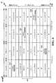
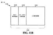
[0064]図11Aは、リソース区分を例示する図1100である。図11Bは、再割り振りされたリソース分配を例示する図1150である。LTE−Dピア発見の場合、チャネルリソースは、2次元リソースブロック(RB)1102として編成されうる。複数のデバイスが同じRB上でそれらのそれぞれのピア発見信号を同時に送るときに信号衝突が生じえ、したがって、どの信号も発見されないことがありうる。 [0064] FIG. 11A is a diagram 1100 illustrating resource partitioning. FIG. 11B is a diagram 1150 illustrating reallocated resource distribution. For LTE-D peer discovery, channel resources may be organized as a two-dimensional resource block (RB) 1102. When multiple devices send their respective peer discovery signals simultaneously on the same RB, a signal collision can occur and therefore no signal can be discovered.
[0065]図11Aを参照すると、ネットワーク輻輳は、リソースブロック1102全体を共有および専用領域に区分/分割することによって緩和されうる。MTC専用領域1104は、MTCデバイス(すなわち、UEではない)による使用のために割り振られた領域でありうる。UE専用領域1108は、UE(すなわち、MTCデバイスではない)による使用のために割り振られた領域でありうる。UE−MTC共有領域1106は、UEおよびMTCデバイスの両方による使用のために割り振られた領域でありうる。ある態様において、リソースブロック区分は、論理ドメインまたは物理ドメイン中でなされうる。さらなる態様において、リソースブロック区分は、MTCデバイスによって自律的に決められうるか、またはUEあるいはeNBによって制御されうる。 [0065] Referring to FIG. 11A, network congestion may be mitigated by partitioning / partitioning the
[0066]ある態様において、ネットワーク輻輳は、ある時間期間の間、MTCデバイスがバックオフすること(リソースの使用を制限すること)を容易にすることによって緩和されうる。バックオフするという決定は、リソースブロック1102上の、具体的には、それぞれMTC専用領域1104、UE専用領域1108、およびUE−MTC共有領域1106中での信号品質測定値、および互いに品質測定値を比較することに依存しうる。測定された信号品質は、例えば、信号電力、信号対雑音比、および発見されたUE/MTCデバイスの数を含みうる。リソースブロック区分と同様に、バックオフするという決定は、MTCデバイスによって自律的になされうるか、またはUEあるいはeNBによって制御されうる。 [0066] In an aspect, network congestion may be mitigated by facilitating the MTC device to back off (limit resource usage) for a period of time. The decision to back off is determined by signal quality measurements on the
[0067]ある態様において、MTCデバイスは、輻輳制御を起動/管理することを自律的に決めうる。輻輳制御を管理するために、MTCデバイスは、ネットワークが輻輳状態にあるどうかを決めるために、ローカル(近くの)ネットワーク輻輳レベルをモニタしうる。輻輳レベルは、それぞれMTC専用領域1104、UE専用領域1108、およびUE−MTC共有領域1106中でのリソースブロック1102上の信号品質を測定し、互いに測定された信号品質を比較することによって推定されうる。例えば、UE−MTC共有領域1106中でのリソースブロック1102上の平均信号電力が、UE専用領域1108中でのリソースブロック1102上の平均信号電力よりも著しく大きい場合、ネットワークは、輻輳状態にあり、MTCデバイスでの自律的輻輳制御メカニズムが、トリガされうる。 [0067] In an aspect, the MTC device may autonomously decide to activate / manage congestion control. To manage congestion control, the MTC device may monitor local (near) network congestion levels to determine whether the network is in a congestion state. The congestion level can be estimated by measuring the signal quality on the
[0068]輻輳制御メカニズムがトリガされるとき、MTCデバイスは、輻輳制御を緩和するために様々な動作を遂行しうる。例えば、MTCデバイスは、ネットワークがもはや輻輳状態でなくなるまで、ある時間期間の間(例えば、バックオフウィンドウ中)、バックオフすること(リソースの使用を制限すること)を選びうる。バックオフするとき、MTCデバイスは、リソースブロック1102の使用をMTC専用領域1104に制限しうる。加えてまたは代替として、MTCデバイスは、UE−MTC共有領域1106を使用するための選好を下げ、下げられた選好に基づいてUE−MTC共有領域1106を使用することによって、リソースブロック1102の使用を制限しうる。バックオフウィンドウ中に、MTCデバイスは、スリープモードに入りうるか、またはローカルネットワーク輻輳レベルをモニタし続けうる。バックオフウィンドウが終了したとき、MTCデバイスは、上述された動作に基づいて輻輳制御を起動/管理するかどうかを再び決めうる。 [0068] When a congestion control mechanism is triggered, the MTC device may perform various operations to mitigate congestion control. For example, the MTC device may choose to back off (limit resource usage) for a period of time (eg, during a backoff window) until the network is no longer congested. When backoff, the MTC device may restrict the use of the
[0069]ある態様において、UEもまた、ネットワーク輻輳を緩和するために、ローカルネットワーク輻輳レベルをモニタし、周囲のMTCデバイス/UEを管理しうる。MTCデバイスと同様に、UEは、それぞれMTC専用領域1104、UE専用領域1108、およびUE−MTC共有領域1106中でのリソースブロック1102上の信号品質を測定し、互いに測定された信号品質を比較することによってネットワークが輻輳状態にあるかどうかを検出/決定しうる。例えば、UE−MTC共有領域1106中でのリソースブロック1102上の平均信号電力が、UE専用領域1108中でのリソースブロック1102上の平均信号電力よりも著しく大きい場合、ネットワークは、輻輳状態にありうる。 [0069] In an aspect, the UE may also monitor the local network congestion level and manage surrounding MTC devices / UEs to mitigate network congestion. Similar to the MTC device, the UE measures the signal quality on the
[0070]ネットワーク輻輳が検出されるとき、UEは、MTCデバイス/UEが輻輳を緩和するためのアクションを遂行することを促すために、輻輳制御信号(例えば、図10中の信号1024、1026、および1028)を周囲のMTCデバイス/UEにブロードキャストしうる。輻輳制御信号は、ネットワーク輻輳を決定するためのしきい値、ネットワーク輻輳レベル、要求されたバックオフの量(例えば、リソースブロック1102のMTC専用領域、UE専用領域、および/または、UE−MTC共有領域を使用することを控えるために要求された量の時間またはアクセス確率)、MTCデバイス識別子、UE識別子、および/または、輻輳を緩和するためのアクションを遂行すべきMTCデバイス/UEのグループの識別子を含みうる。図11Bを参照すると、UEはまた、リソースブロック1102のリソースを、再割り振りされたMTC専用領域1110、再割り振りされたUE専用領域1114、および再割り振りされたUE−MTC共有領域1112に再区分/再割り振りしうる。リソース区分情報もまた、輻輳制御信号中に含まれうる。輻輳制御信号を受信した後で、MTCデバイスは、割り振られたチャネルリソースを使用することを制限されえ、したがって、輻輳制御信号中で要求された量の時間の間、そのようなリソースを使用することからバックオフする。代替として、MTCデバイスは、輻輳レベルにしたがってバックオフ時間の量を自律的に決定しうる。 [0070] When network congestion is detected, the UE may use congestion control signals (eg, signals 1024, 1026, FIG. 10 in FIG. 10) to prompt the MTC device / UE to take action to mitigate the congestion. And 1028) may be broadcast to surrounding MTC devices / UEs. The congestion control signal may include a threshold for determining network congestion, a network congestion level, a requested amount of backoff (eg, MTC dedicated area, UE dedicated area and / or UE-MTC sharing of resource block 1102). The amount of time or access probability required to refrain from using the region), the MTC device identifier, the UE identifier, and / or the identifier of the group of MTC devices / UEs to perform actions to mitigate congestion Can be included. Referring to FIG. 11B, the UE also repartitions / resources the
[0071]ある態様において、eNBは、ネットワーク全体について輻輳制御を支援しうる。UEは、ローカル輻輳レベルをeNBに周期的にレポートしうる。UEはまた、UEがバックオフしたいと望む周囲のMTCデバイス/UEのグループの識別子および/またはピア発見パフォーマンスのような他の情報をレポートしうる。レポートされた情報にしたがって、eNBは、リソースブロック1102のリソースを、再割り振りされたMTC専用領域1110、再割り振りされたUE専用領域1114、および再割り振りされたUE−MTC共有領域1112に再区分/再割り振りしうる。eNBは、リソースブロック1102中で使用するためのリソースをいつ切り替えるかを示す、ネットワーク中のUEのためのしきい値(再シャッフルしきい値(reshuffle threshold))を指定しうる。eNBはまた、ネットワーク中のMTCデバイス/UEのグループについてバックオフタイムの量を指定しうる。 [0071] In an aspect, the eNB may support congestion control for the entire network. The UE may periodically report the local congestion level to the eNB. The UE may also report other information such as identifiers of surrounding MTC devices / UE groups that the UE wishes to back off and / or peer discovery performance. According to the reported information, the eNB repartitions / resources the
[0072]eNBは、ネットワーク規模の輻輳制御信号(例えば、図10中の信号1022)をネットワーク中の全てのUEおよびMTCデバイスにブロードキャストしうる。輻輳制御信号は、ネットワーク輻輳を決定するためのしきい値、ローカル輻輳レベル、ネットワーク輻輳レベル、リソース区分情報、UEのための再シャッフルしきい値、要求されたバックオフの量(例えば、リソースブロック1102のMTC専用領域、UE専用領域、および/または、UE−MTC共有領域を使用することを控えるために要求された量の時間またはアクセス確率)、MTC識別子、UE識別子、および/または、輻輳を緩和するためのアクションを遂行すべきターゲットMTCデバイス/UEのグループの識別子を含みうる。輻輳制御信号を受信した後で、ネットワークのターゲットMTCデバイス/UEは、割り振られたチャネルを使用することを制限されえ、したがって、輻輳制御信号中で要求された量の時間の間、そのようなリソースを使用することからバックオフする。代替として、MTCデバイス/UEは、輻輳レベルにしたがってバックオフ時間の量を自律的に決定しうる。UEはさらに、輻輳制御信号中に含まれた再シャッフルしきい値にしたがって、リソースブロック1102中で使用するためのリソースを切り替えうる。 [0072] The eNB may broadcast a network-wide congestion control signal (eg,
[0073]ある態様において、通信ネットワークは、中央コントローラノード(CCN:central controller node)、永続的アクセスデバイス(PAD:persistent access device)、および一時的ランダムアクセスデバイス(TRAD:temporarily random access device)の3つのタイプのデバイスを含みうる。ある態様において、CCNの例は、eNBであり、PADの例は、UEであり、TRADの例は、MTCデバイスである。CCNは、ネットワークの中央コントローラとして機能しうる。PADは、CCNとのアップリンクおよびダウンリンク接続の両方が可能な高電力デバイスでありうる。TRADは、CCNとのダウンリンク接続は可能だが、アップリンク接続は可能でない、低電力デバイスでありうる。PADおよびTRADは、他の周囲のPADおよびTRADとの接続が可能でありうる。PADおよびTRADは、共通ピア発見チャネル上でピア発見信号を送りえ、全ての周囲のPADおよびTRADは、そのようなピア発見信号を復号しうる。ピア発見リソース(例えば、リソースブロック)は、PAD単独によって使用されることができるPAD専用領域、TRAD単独によって使用されることができるTRAD専用領域、およびPADとTRADとの両方によって使用されることができるPAD−TRAD共有領域に分割/区分されうる。リソース区分は、論理ドメイン中または物理ドメイン中でなされうる。輻輳制御は、各PADが可能な限り多くの周囲のPADおよびTRADを発見することができるように、PADおよびTADが信号衝突を避けるために共通チャネルを適切に使用することを可能にする。 [0073] In an aspect, a communication network includes a central controller node (CCN), a persistent access device (PAD), and a temporarily random access device (TRAD). One type of device may be included. In certain aspects, an example of a CCN is an eNB, an example of a PAD is a UE, and an example of a TRAD is an MTC device. The CCN can function as a central controller for the network. A PAD may be a high power device capable of both uplink and downlink connections with a CCN. A TRAD may be a low power device that allows a downlink connection with a CCN but not an uplink connection. PAD and TRAD may be able to connect with other surrounding PADs and TRADs. PAD and TRAD can send peer discovery signals on a common peer discovery channel, and all surrounding PADs and TRADs can decode such peer discovery signals. Peer discovery resources (eg, resource blocks) are used by PAD dedicated regions that can be used by PAD alone, TRAD dedicated regions that can be used by TRAD alone, and by both PAD and TRAD. It can be divided / partitioned into possible PAD-TRAD shared areas. Resource partitioning can be done in a logical domain or in a physical domain. Congestion control allows PADs and TADs to properly use common channels to avoid signal collisions so that each PAD can discover as many surrounding PADs and TRADs as possible.
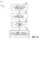
[0074]図12は、輻輳制御の方法のフローチャート1200である。方法は、MTCデバイスによって遂行されうる。ステップ1202では、MTCデバイスは、リソースブロック(例えば、リソースブロック1102)の少なくとも2つの領域中でのそれぞれの信号品質を測定する。それぞれの信号品質を測定することは、リソースブロックの第1の領域中での第1の信号品質、リソースブロックの第2の領域中での第2の信号品質、およびリソースブロックの第3の領域中での第3の信号品質を測定することを含みうる。ある態様において、第1の領域は、少なくとも1つのMTCデバイスに対して割り振られた第1のリソース(例えば、MTC専用領域1104)を含み、第2の領域は、少なくとも1つのMTCデバイスおよび少なくとも1つのUEに対して割り振られた第2のリソース(例えば、UE−MTC共有領域1106)を含み、第3の領域は、少なくとも1つのUEに対して割り振られた第3のリソース(例えば、UE専用領域1108)を含む。ある態様において、第1の信号品質、第2の信号品質、または第3の信号品質は、信号電力、信号対雑音比、発見されたMTCデバイスまたはUEの数、使用されているリソースの数、および/または、UEまたはMTCが発見されることができるリソースの数でありうる。 [0074] FIG. 12 is a
[0075]ステップ1204では、MTCデバイスは、それぞれの信号品質を互いに比較する。MTCデバイスはさらに、測定された信号品質に基づいて、ネットワーク輻輳レベルに関連するしきい値を計算しうる。ステップ1206では、MTCデバイスは、比較に基づいてネットワーク輻輳レベルを決定する。 [0075] In
[0076]ステップ1208では、MTCデバイスは、ネットワーク輻輳レベルに基づいて、少なくとも2つの領域中にそれぞれ含まれたリソースを使用するかどうかを決める。ある態様において、MTCデバイスは、ネットワーク輻輳レベルに基づいて、第1の領域の第1のリソースまたは第2の領域の第2のリソースのうちの少なくとも1つを使用するかどうかを決める。 [0076] In
[0077]さらなる態様においては、MTCデバイスは、ネットワーク輻輳レベルがしきい値を上回るときに、ある時間期間の間、第1の領域の第1のリソースまたは第2の領域の第2のリソースのうちの少なくとも1つを使用することを控えることによって決める。その時間期間中に、MTCデバイスは、スリープモードをアクティブ化しうる。代替として、その時間期間中に、MTCデバイスは、第1の信号品質、第2の信号品質、および第3の信号品質を測定し、第1の信号品質、第2の信号品質、および第3の信号品質を互いに比較し、比較に基づいてネットワーク輻輳レベルを決定し続けうる。 [0077] In a further aspect, the MTC device allows the first resource in the first region or the second resource in the second region for a period of time when the network congestion level exceeds a threshold. Decide by refraining from using at least one of them. During that time period, the MTC device may activate sleep mode. Alternatively, during that time period, the MTC device measures the first signal quality, the second signal quality, and the third signal quality, and the first signal quality, the second signal quality, and the third signal quality are measured. Can be compared with each other and the network congestion level can continue to be determined based on the comparison.
[0078]別の態様においては、MTCデバイスは、ネットワーク輻輳レベルがしきい値を上回るときに、リソースブロックの使用を第1の領域の第1のリソースに制限することによって決める。さらなる別の態様においては、ネットワーク輻輳レベルがしきい値を上回るとき、MTCデバイスは、第2の領域の第2のリソースを使用するための選好を下げ、下げられた選好に基づいて第2の領域の第2のリソースを使用することによって決める。 [0078] In another aspect, the MTC device determines by restricting the use of resource blocks to the first resource in the first region when the network congestion level exceeds a threshold. In yet another aspect, when the network congestion level is above the threshold, the MTC device reduces the preference for using the second resource in the second region and sets the second based on the reduced preference. Decide by using the second resource of the region.
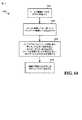
[0079]図13は、輻輳制御の方法のフローチャート1300である。方法は、UEによって遂行されうる。ステップ1302では、UEは、リソースブロック(例えば、リソースブロック1102)の少なくとも2つの領域中でのそれぞれの信号品質を測定しうる。それぞれの信号品質を測定することは、リソースブロックの第1の領域中での第1の信号品質、リソースブロックの第2の領域中での第2の信号品質、およびリソースブロックの第3の領域中での第3の信号品質を測定することを含みうる。ある態様において、第1の領域は、少なくとも1つのMTCデバイスに対して割り振られた第1のリソース(例えば、MTC専用領域1104)を含み、第2の領域は、少なくとも1つのMTCデバイスおよび少なくとも1つのUEに対して割り振られた第2のリソース(UE−MTC共有領域1106)を含み、第3の領域は、少なくとも1つのUEに対して割り振られた第3のリソース(UE専用領域1108)を含む。ある態様において、第1の信号品質、第2の信号品質、または第3の信号品質は、信号電力、信号対雑音比、発見されたMTCデバイスまたはUEの数、使用されているリソースの数、および/または、UEまたはMTCデバイスが発見されることができるリソースの数でありうる。 [0079] FIG. 13 is a
[0080]ステップ1304では、UEは、それぞれの信号品質を互いに比較する。UEはさらに、測定された信号品質に基づいて、ネットワーク輻輳レベルに関連するしきい値を計算しうる。ステップ1306では、UEは、比較に基づいてネットワーク輻輳レベルを決定する。 [0080] In
[0081]ステップ1308では、UEは、ネットワーク輻輳レベルがしきい値を上回るときに、少なくとも2つの領域中にそれぞれ含まれたリソースを使用することを控えるために、少なくとも1つのMTCデバイスまたは他のUEを識別する。ある態様においては、UEは、ネットワーク輻輳レベルがしきい値を上回るときに、第1のリソース、第2のリソース、または第3のリソースのうちの少なくとも1つを使用することを控えるために、少なくとも1つのMTCデバイスまたは他のUEを識別することによって識別する。 [0081] In
[0082]ステップ1310では、UEは、ネットワーク輻輳レベルに基づいて、リソースブロックの第1のリソース、第2のリソース、および第3のリソースを再割り振りする。再割り振りすることは、リソースブロックを再割り振りされた第1の領域、再割り振りされた第2の領域、および再割り振りされた第3の領域に分割することを含みうる。再割り振りされた第1の領域は、少なくとも1つのMTCデバイスに対して再割り振りされた第1のリソース(例えば、再割り振りされたMTC専用領域1110)を含みうる。再割り振りされた第2の領域は、少なくとも1つのMTCデバイスおよび少なくとも1つのUEに対して再割り振りされた第2のリソース(例えば、再割り振りされたUE−MTC共有領域1112)を含みうる。再割り振りされた第3の領域は、少なくとも1つのUEに対して再割り振りされた第3のリソース(例えば、再割り振りされたUE専用領域1114)を含みうる。 [0082] In
[0083]ステップ1312では、UEは、ネットワーク輻輳レベルがしきい値を上回るときに、輻輳制御信号を少なくとも1つの識別されたMTCデバイスまたは他の識別されたUEに送信する。輻輳制御信号は、ネットワーク輻輳を決定するためのしきい値、ネットワーク輻輳レベル、第1のリソース、第2のリソース、または第3のリソースのうちの少なくとも1つを使用することを控えるために要求された量の時間、MTCデバイス識別子、UE識別子、および/または、リソース割り振り情報を含みうる。 [0083] In
[0084]図14は、輻輳制御の方法のフローチャート1400である。方法は、基地局(例えば、eNB)によって遂行されうる。ステップ1402では、基地局は、少なくとも1つのローカル輻輳レベルをそれぞれ少なくとも1つのUEから受信する。ステップ1404では、基地局は、少なくとも1つのローカル輻輳レベルに基づいてネットワーク輻輳レベルを決定する。 [0084] FIG. 14 is a
[0085]ステップ1406では、少なくとも1つのローカル輻輳レベルまたはネットワーク輻輳レベルに基づいて、基地局は、1つまたは複数のアクションを遂行しうる。例えば、基地局は、リソースブロック(例えば、リソースブロック1102)のリソースを第1の領域、第2の領域、および第3の領域に割り振りえ、第1の領域は、少なくとも1つのMTCデバイスに対して割り振られた第1のリソース(例えば、MTC専用領域1104)を含み、第2の領域は、少なくとも1つのMTCデバイスおよび少なくとも1つのUEに対して割り振られた第2のリソース(例えば、UE−MTC共有領域1106)を含み、第3の領域は、少なくとも1つのUEに対して割り振られた第3のリソース(例えば、UE専用領域1108)を含む。別の例において、基地局は、少なくとも1つのUEのための再シャッフルしきい値を決定しうる。さらなる例において、基地局は、第1のリソース、第2のリソース、または第3のリソースのうちの少なくとも1つを使用することを控えるために、少なくとも1つのMTCデバイスまたはUEを識別しうる。 [0085] In
[0086]ステップ1408では、基地局は、ネットワーク輻輳レベルに基づいて、輻輳制御信号を少なくとも1つのUEおよび/または少なくとも1つのMTCデバイスに送信する。輻輳制御信号は、ネットワーク輻輳を決定するためのしきい値、少なくとも1つのローカル輻輳レベル、ネットワーク輻輳レベル、リソースブロックのリソース割り振り、少なくとも1つのUEのための再シャッフルしきい値、第1のリソース、第2のリソース、または第3のリソースのうちの少なくとも1つを使用することを控えるために要求された量の時間、MTCデバイス識別子、および/または、UE識別子を含みうる。 [0086] In
[0087]図15は、例証的な装置1502中の異なるモジュール/手段/コンポーネント間でのデータフローを例示する概念的なデータフロー図1500である。装置は、UE1550と信号を通信する、および/または、基地局1570から信号を受信する、MTCデバイスでありうる。装置は、受信モジュール1504、信号品質処理モジュール1506、輻輳制御モジュール1508、リソース使用決定モジュール1510、および送信モジュール1512を含む。 [0087] FIG. 15 is a conceptual data flow diagram 1500 illustrating data flow between different modules / means / components in an
[0088]信号品質処理モジュール1506は、リソースブロック(例えば、リソースブロック1102)の少なくとも2つの領域中での(受信モジュール1504を介して受信された信号の)それぞれの信号品質を測定する。それぞれの信号品質を測定することは、リソースブロックの第1の領域中での第1の信号品質、リソースブロックの第2の領域中での第2の信号品質、およびリソースブロックの第3の領域中での第3の信号品質を測定することを含みうる。ある態様において、第1の領域は、少なくとも1つのMTCデバイスに対して割り振られた第1のリソース(例えば、MTC専用領域1104)を含み、第2の領域は、少なくとも1つのMTCデバイスおよび少なくとも1つのUEに対して割り振られた第2のリソース(例えば、UE−MTC共有領域1106)を含み、第3の領域は、少なくとも1つのUEに対して割り振られた第3のリソース(例えば、UE専用領域1108)を含む。ある態様において、第1の信号品質、第2の信号品質、または第3の信号品質は、信号電力、信号対雑音比、発見されたMTCデバイスまたはUEの数、使用されているリソースの数、および/または、UEまたはMTCが発見されることができるリソースの数でありうる。 [0088] The signal
[0089]輻輳制御モジュール1508は、それぞれの信号品質を互いに比較する。輻輳制御モジュール1508はまた、測定された信号品質に基づいて、ネットワーク輻輳レベルに関連するしきい値を計算しうる。輻輳制御モジュール1508はさらに、比較に基づいてネットワーク輻輳レベルを決定する。 [0089] The
[0090]リソース使用決定モジュール1510は、ネットワーク輻輳レベルに基づいて、少なくとも2つの領域中にそれぞれ含まれたリソースを使用するかどうかを決める。ある態様において、リソース使用決定モジュール1510は、ネットワーク輻輳レベルに基づいて、第1の領域の第1のリソースまたは第2の領域の第2のリソースのうちの少なくとも1つを使用するかどうかを決める。 [0090] The resource
[0091]さらなる態様においては、リソース使用決定モジュール1510は、ネットワーク輻輳レベルがしきい値を上回るときに、ある時間期間の間、第1の領域の第1のリソースまたは第2の領域の第2のリソースのうちの少なくとも1つを使用することを控えることによって決める。その時間期間中に、輻輳制御モジュール1508は、スリープモードをアクティブ化しうる。代替として、その時間期間中に、信号品質処理モジュール1506は、第1の信号品質、第2の信号品質、および第3の信号品質を測定し続け、輻輳制御モジュール1508は、第1の信号品質、第2の信号品質、および第3の信号品質を互いに比較し、比較に基づいてネットワーク輻輳レベルを決定し続けうる。 [0091] In a further aspect, the resource
[0092]別の態様においては、リソース使用決定モジュール1510は、ネットワーク輻輳レベルがしきい値を上回るときに、リソースブロックの使用を第1の領域の第1のリソースに制限することによって決める。さらなる別の態様においては、ネットワーク輻輳レベルがしきい値を上回るとき、リソース使用決定モジュール1510は、第2の領域の第2のリソースを使用するための選好を下げ、下げられた選好に基づいて第2の領域の第2のリソースを使用することによって決める。 [0092] In another aspect, the resource
[0093]装置は、前述された図12のフローチャート中のアルゴリズムのステップの各々を遂行する追加のモジュールを含みうる。そのため、前述された図12のフローチャート中の各ステップは、モジュールによって遂行され、装置は、それらのモジュールのうちの1つまたは複数を含みうる。モジュールは、記載された処理/アルゴリズムを行うように特に構成された1つまたは複数のハードウェアコンポーネントでありうるか、記載された処理/アルゴリズムを遂行するように構成されたプロセッサによってインプリメントされうるか、プロセッサによるインプリメンテーションのためにコンピュータ可読媒体内に記憶されうるか、またはそれらの何らかの組み合わせでありうる。 [0093] The apparatus may include additional modules that perform each of the steps of the algorithm in the flowchart of FIG. 12 described above. Therefore, each step in the flowchart of FIG. 12 described above is performed by modules, and the apparatus may include one or more of those modules. A module may be one or more hardware components specifically configured to perform the described processing / algorithm, or may be implemented by a processor configured to perform the described processing / algorithm, or processor Can be stored in a computer readable medium for implementation by or some combination thereof.
[0094]図16は、例証的な装置1602中の異なるモジュール/手段/コンポーネント間でのデータフローを例示する概念的なデータフロー図1600である。装置は、別のUE1650、基地局1670、および/またはMTCデバイス1690と信号を通信するUEでありうる。装置は、受信モジュール1604、信号品質処理モジュール1606、輻輳制御モジュール1608、識別モジュール1610、リソース再割り振りモジュール1612、および送信モジュール1614を含む。 [0094] FIG. 16 is a conceptual data flow diagram 1600 illustrating data flow between different modules / means / components in an
[0095]信号品質処理モジュール1606は、リソースブロック(例えば、リソースブロック1102)の少なくとも2つの領域中での(受信モジュール1604を介して受信された信号の)それぞれの信号品質を測定しうる。それぞれの信号品質を測定することは、リソースブロックの第1の領域中での第1の信号品質、リソースブロックの第2の領域中での第2の信号品質、およびリソースブロックの第3の領域中での第3の信号品質を測定することを含みうる。ある態様において、第1の領域は、少なくとも1つのMTCデバイスに対して割り振られた第1のリソース(例えば、MTC専用領域1104)を含み、第2の領域は、少なくとも1つのMTCデバイスおよび少なくとも1つのUEに対して割り振られた第2のリソース(UE−MTC共有領域1106)を含み、第3の領域は、少なくとも1つのUEに対して割り振られた第3のリソース(UE専用領域1108)を含む。ある態様において、第1の信号品質、第2の信号品質、または第3の信号品質は、信号電力、信号対雑音比、発見されたMTCデバイスまたはUEの数、使用されているリソースの数、および/または、UEまたはMTCデバイスが発見されることができるリソースの数でありうる。 [0095] The signal
[0096]輻輳制御モジュール1608は、それぞれの信号品質を互いに比較する。輻輳制御モジュール1608はまた、測定された信号品質に基づいて、ネットワーク輻輳レベルに関連するしきい値を計算しうる。輻輳制御モジュール1608はさらに、比較に基づいてネットワーク輻輳レベルを決定する。 [0096] The
[0097]識別モジュール1610は、ネットワーク輻輳レベルがしきい値を上回るときに、少なくとも2つの領域中にそれぞれ含まれたリソースを使用することを控えるために、少なくとも1つのMTCデバイス(例えば、MTCデバイス1690)または他のUE(例えば、他のUE1650)を識別する。ある態様においては、識別モジュール1610は、ネットワーク輻輳レベルがしきい値を上回るときに、第1のリソース、第2のリソース、または第3のリソースのうちの少なくとも1つを使用することを控えるために、少なくとも1つのMTCデバイス1690または他のUE1650を識別することによって識別する。 [0097] The
[0098]リソース再割り振りモジュール1612は、ネットワーク輻輳レベルに基づいて、リソースブロックの第1のリソース、第2のリソース、および第3のリソースを再割り振りする。再割り振りすることは、リソースブロックを再割り振りされた第1の領域、再割り振りされた第2の領域、および再割り振りされた第3の領域に分割することを含みうる。再割り振りされた第1の領域は、少なくとも1つのMTCデバイスに対して再割り振りされた第1のリソース(例えば、再割り振りされたMTC専用領域1110)を含みうる。再割り振りされた第2の領域は、少なくとも1つのMTCデバイスおよび少なくとも1つのUEに対して再割り振りされた第2のリソース(例えば、再割り振りされたUE−MTC共有領域1112)を含みうる。再割り振りされた第3の領域は、少なくとも1つのUEに対して再割り振りされた第3のリソース(例えば、再割り振りされたUE専用領域1114)を含みうる。 [0098] The
[0099]輻輳制御信号1608は、ネットワーク輻輳レベルがしきい値を上回るときに、輻輳制御信号を少なくとも1つの識別されたMTCデバイス1690または他の識別されたUE1650に(送信モジュール1614を介して)送信する。輻輳制御信号は、ネットワーク輻輳を決定するためのしきい値、ネットワーク輻輳レベル、第1のリソース、第2のリソース、または第3のリソースのうちの少なくとも1つを使用することを控えるために要求された量の時間、MTCデバイス識別子、UE識別子、および/または、リソース割り振り情報を含みうる。 [0099] The
[00100]装置は、前述された図13のフローチャート中のアルゴリズムのステップの各々を遂行する追加のモジュールを含みうる。そのため、前述された図13のフローチャート中の各ステップは、モジュールによって遂行され、装置は、それらのモジュールのうちの1つまたは複数を含みうる。モジュールは、記載された処理/アルゴリズムを行うように特に構成された1つまたは複数のハードウェアコンポーネントでありうるか、記載された処理/アルゴリズムを遂行するように構成されたプロセッサによってインプリメントされうるか、プロセッサによるインプリメンテーションのためにコンピュータ可読媒体内に記憶されうるか、またはそれらの何らかの組み合わせでありうる。 [00100] The apparatus may include additional modules that perform each of the steps of the algorithm in the flowchart of FIG. 13 described above. Therefore, each step in the flowchart of FIG. 13 described above is performed by modules, and the apparatus may include one or more of those modules. A module may be one or more hardware components specifically configured to perform the described processing / algorithm, or may be implemented by a processor configured to perform the described processing / algorithm, or processor Can be stored in a computer readable medium for implementation by or some combination thereof.
[00101]図17は、例証的な装置1702中の異なるモジュール/手段/コンポーネント間でのデータフローを例示する概念的なデータフロー図1700である。装置は、基地局(例えば、eNB)でありうる。装置は、受信モジュール1704、輻輳制御モジュール1706、識別モジュール1710、リソース再割り振りモジュール1710、および送信モジュール1712を含む。 [00101] FIG. 17 is a conceptual data flow diagram 1700 illustrating data flow between different modules / means / components in an
[00102]輻輳制御モジュールは、少なくとも1つのローカル輻輳レベルをそれぞれ少なくとも1つのUE(例えば、1750)から(受信モジュール1704を介して)受信する。輻輳制御モジュール1706は、少なくとも1つのローカル輻輳レベルに基づいてネットワーク輻輳レベルを決定する。 [00102] The congestion control module receives (via the receiving module 1704) at least one local congestion level from each of at least one UE (eg, 1750). The
[00103]少なくとも1つのローカル輻輳レベルまたはネットワーク輻輳レベルに基づいて、装置1702は、1つまたは複数のアクションを遂行しうる。例えば、リソース再割り振りモジュール1710は、リソースブロック(例えば、リソースブロック1102)のリソースを第1の領域、第2の領域、および第3の領域に割り振りえ、第1の領域は、少なくとも1つのMTCデバイスに対して割り振られた第1のリソース(例えば、MTC専用領域1104)を含み、第2の領域は、少なくとも1つのMTCデバイスおよび少なくとも1つのUEに対して割り振られた第2のリソース(例えば、UE−MTC共有領域1106)を含み、第3の領域は、少なくとも1つのUEに対して割り振られた第3のリソース(例えば、UE専用領域1108)を含む。別の例において、リソース再割り振りモジュール1710および/または輻輳制御モジュール1706は、少なくとも1つのUE1750のための再シャッフルしきい値を決定しうる。さらなる例において、識別モジュール1708は、第1のリソース、第2のリソース、または第3のリソースのうちの少なくとも1つを使用することを控えるために、少なくとも1つのMTCデバイス(例えば、MTCデバイス1770)またはUE1750を識別しうる。 [00103] Based on at least one local congestion level or network congestion level, the
[00104]輻輳制御モジュール1706は、ネットワーク輻輳レベルに基づいて、輻輳制御信号を少なくとも1つのUE1750および/または少なくとも1つのMTCデバイス1770に(送信モジュールを介して)送信する。輻輳制御信号は、ネットワーク輻輳を決定するためのしきい値、少なくとも1つのローカル輻輳レベル、ネットワーク輻輳レベル、リソースブロックのリソース割り振り、少なくとも1つのUEのための再シャッフルしきい値、第1のリソース、第2のリソース、または第3のリソースのうちの少なくとも1つを使用することを控えるために要求された量の時間、MTCデバイス識別子、および/または、UE識別子を含みうる。 [00104] The
[00105]装置は、前述された図14のフローチャート中のアルゴリズムのステップの各々を遂行する追加のモジュールを含みうる。そのため、前述された図14のフローチャート中の各ステップは、モジュールによって遂行され、装置は、それらのモジュールのうちの1つまたは複数を含みうる。モジュールは、記載された処理/アルゴリズムを行うように特に構成された1つまたは複数のハードウェアコンポーネントでありうるか、記載された処理/アルゴリズムを遂行するように構成されたプロセッサによってインプリメントされうるか、プロセッサによるインプリメンテーションのためにコンピュータ可読媒体内に記憶されうるか、またはそれらの何らかの組み合わせでありうる。 [00105] The apparatus may include additional modules that perform each of the steps of the algorithm in the flowchart of FIG. 14 described above. Thus, each step in the flowchart of FIG. 14 described above is performed by modules, and the apparatus may include one or more of those modules. A module may be one or more hardware components specifically configured to perform the described processing / algorithm, or may be implemented by a processor configured to perform the described processing / algorithm, or processor Can be stored in a computer readable medium for implementation by or some combination thereof.
[00106]図18は、処理システム1814を用いる装置1502’のためのハードウェアインプリメンテーションの例を例示する図1800である。処理システム1814は、一般にバス1824によって表される、バスアーキテクチャを用いてインプリメントされうる。バス1824は、処理システム1814の特定のアプリケーションおよび全体的な設計制約に依存して、任意の数の相互接続バスおよびブリッジを含みうる。バス1824は、プロセッサ1804、モジュール1504、1506、1508、1510、1512、およびコンピュータ可読媒体/メモリ1806によって表される、1つまたは複数のプロセッサおよび/またはハードウェアモジュールを含む様々な回路をともにリンクする。バス1824はまた、タイミングソース、周辺機器、電圧レギュレータ、および電力管理回路のような様々な他の回路をリンクしうるが、それらは、当該技術において良く知られており、したがって、これ以上は説明されない。 [00106] FIG. 18 is a drawing 1800 illustrating an example of a hardware implementation for an apparatus 1502 'using a
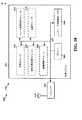
[00107]処理システム1814は、トランシーバ1810に結合されうる。トランシーバ1810は、1つまたは複数のアンテナ1820に結合される。トランシーバ1810は、送信媒体を通じて様々な他の装置と通信するための手段を提供する。トランシーバ1810は、1つまたは複数のアンテナ1820から信号を受信し、受信された信号から情報を抽出し、抽出された情報を処理システム1814、具体的には受信モジュール1504に提供する。加えて、トランシーバ1810は、処理システム1814、具体的には送信モジュール1512から情報を受信し、受信された情報に基づいて、1つまたは複数のアンテナ1820に適用される信号を生成する。処理システム1814は、コンピュータ可読媒体/メモリ1806に結合されたプロセッサ1804を含む。プロセッサ1804は、コンピュータ可読媒体/メモリ1806上に記憶されたソフトウェアの実行を含む、一般の処理を担う。ソフトウェアは、プロセッサ1804によって実行されたとき、処理システム1814に、任意の特定の装置に関して上記に説明された様々な機能を遂行させる。コンピュータ可読媒体/メモリ1806はまた、ソフトウェアを実行するときにプロセッサ1804によって操作されるデータを記憶するために使用されうる。処理システムはさらに、モジュール1504、1506、1508、1510、および1512のうちの少なくとも1つを含む。モジュールは、プロセッサ1804中で実行中であり、コンピュータ可読媒体/メモリ1806中に存在する/記憶されたソフトウェアモジュール、プロセッサ1804に結合された1つまたは複数のハードウェアモジュール、またはそれらの何らかの組み合わせでありうる。処理システム1814は、UE/MTCデバイス650のコンポーネントであり、メモリ660および/またはTXプロセッサ668、RXプロセッサ656、およびコントローラ/プロセッサ659のうちの少なくとも1つを含みうる。 [00107] The
[00108]一構成において、ワイヤレス通信のための装置1502/1502’は、リソースブロックの少なくとも2つの領域中でのそれぞれの信号品質を測定するための手段と、それぞれの信号品質を互いに比較するための手段と、測定された信号品質に基づいてしきい値を計算するための手段と、比較に基づいてネットワーク輻輳レベルを決定するための手段と、ネットワーク輻輳レベルに基づいて、少なくとも2つの領域中にそれぞれ含まれたリソースを使用するかどうかを決めるための手段とを含む。 [00108] In one configuration, an
[00109]前述された手段は、前述された手段によって記載された機能を遂行するように構成された装置1502’の処理システム1814、および/または、装置1502の前述されたモジュールのうちの1つまたは複数でありうる。上記に説明されたように、処理システム1814は、TXプロセッサ668、RXプロセッサ656、およびコントローラ/プロセッサ659を含みうる。そのため、一構成において、前述された手段は、前述された手段によって記載された機能を遂行するように構成されたTXプロセッサ668、RXプロセッサ656、およびコントローラ/プロセッサ659でありうる。 [00109] The aforementioned means is one of the
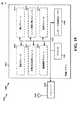
[00110]図19は、処理システム1914を用いる装置1602’のためのハードウェアインプリメンテーションの例を例示する図1900である。処理システム1914は、一般にバス1924によって表される、バスアーキテクチャを用いてインプリメントされうる。バス1924は、処理システム1914の特定のアプリケーションおよび全体的な設計制約に依存して、任意の数の相互接続バスおよびブリッジを含みうる。バス1924は、プロセッサ1904、モジュール1604、1606、1608、1610、1612、1614、およびコンピュータ可読媒体/メモリ1906によって表される、1つまたは複数のプロセッサおよび/またはハードウェアモジュールを含む様々な回路をともにリンクする。バス1924はまた、タイミングソース、周辺機器、電圧レギュレータ、および電力管理回路のような様々な他の回路をリンクしうるが、それらは、当該技術において良く知られており、したがって、これ以上は説明されない。 [00110] FIG. 19 is a drawing 1900 illustrating an example of a hardware implementation for an apparatus 1602 'using a
[00111]処理システム1914は、トランシーバ1910に結合されうる。トランシーバ1910は、1つまたは複数のアンテナ1920に結合される。トランシーバ1910は、送信媒体を通じて様々な他の装置と通信するための手段を提供する。トランシーバ1910は、1つまたは複数のアンテナ1920から信号を受信し、受信された信号から情報を抽出し、抽出された情報を処理システム1914、具体的には受信モジュール1604に提供する。加えて、トランシーバ1910は、処理システム1914、具体的には送信モジュール1614から情報を受信し、受信された情報に基づいて、1つまたは複数のアンテナ1920に適用される信号を生成する。処理システム1914は、コンピュータ可読媒体/メモリ1906に結合されたプロセッサ1904を含む。プロセッサ1904は、コンピュータ可読媒体/メモリ1906上に記憶されたソフトウェアの実行を含む、一般の処理を担う。ソフトウェアは、プロセッサ1904によって実行されたとき、処理システム1914に、任意の特定の装置に関して上記に説明された様々な機能を遂行させる。コンピュータ可読媒体/メモリ1906はまた、ソフトウェアを実行するときにプロセッサ1904によって操作されるデータを記憶するために使用されうる。処理システムはさらに、モジュール1604、1606、1608、1610、1612、および1614のうちの少なくとも1つを含む。モジュールは、プロセッサ1904中で実行中であり、コンピュータ可読媒体/メモリ1906中に存在する/記憶されたソフトウェアモジュール、プロセッサ1904に結合された1つまたは複数のハードウェアモジュール、またはそれらの何らかの組み合わせでありうる。処理システム1914は、UE650のコンポーネントであり、メモリ660および/またはTXプロセッサ668、RXプロセッサ656、およびコントローラ/プロセッサ659のうちの少なくとも1つを含みうる。 [00111] The
[00112]一構成において、ワイヤレス通信のための装置1602/1602’は、リソースブロックの少なくとも2つの領域中でのそれぞれの信号品質を測定するための手段と、それぞれの信号品質を互いに比較するための手段と、比較に基づいてネットワーク輻輳レベルを決定するための手段と、測定された信号品質に基づいてしきい値を計算するための手段と、ネットワーク輻輳レベルがしきい値を上回るときに、少なくとも2つの領域中にそれぞれ含まれたリソースを使用することを控えるために、少なくとも1つのマシンタイプ通信(MTC)デバイスまたは他のUEを識別するための手段と、ネットワーク輻輳レベルがしきい値を上回るときに、輻輳制御信号を少なくとも1つの識別されたMTCデバイスまたは他の識別されたUEに送信するための手段と、ネットワーク輻輳レベルに基づいて、リソースブロックの第1のリソース、第2のリソース、および第3のリソースを再割り振りするための手段とを含む。 [00112] In one configuration, an
[00113]前述された手段は、前述された手段によって記載された機能を遂行するように構成された装置1602’の処理システム1914、および/または、装置1602の前述されたモジュールのうちの1つまたは複数でありうる。上記に説明されたように、処理システム1914は、TXプロセッサ668、RXプロセッサ656、およびコントローラ/プロセッサ659を含みうる。そのため、一構成において、前述された手段は、前述された手段によって記載された機能を遂行するように構成されたTXプロセッサ668、RXプロセッサ656、およびコントローラ/プロセッサ659でありうる。 [00113] The means described above is one of the
[00114]図20は、処理システム2014を用いる装置1702’のためのハードウェアインプリメンテーションの例を例示する図2000である。処理システム2014は、一般にバス2024によって表される、バスアーキテクチャを用いてインプリメントされうる。バス2024は、処理システム2014の特定のアプリケーションおよび全体的な設計制約に依存して、任意の数の相互接続バスおよびブリッジを含みうる。バス2024は、プロセッサ2004、モジュール1704、1706、1708、1710、1712、およびコンピュータ可読媒体/メモリ2006によって表される、1つまたは複数のプロセッサおよび/またはハードウェアモジュールを含む様々な回路をともにリンクする。バス2024はまた、タイミングソース、周辺機器、電圧レギュレータ、および電力管理回路のような様々な他の回路をリンクしうるが、それらは、当該技術において良く知られており、したがって、これ以上は説明されない。 [00114] FIG. 20 is a diagram 2000 illustrating an example of a hardware implementation for an apparatus 1702 'using the
[00115]処理システム2014は、トランシーバ2010に結合されうる。トランシーバ2010は、1つまたは複数のアンテナ2020に結合される。トランシーバ2010は、送信媒体を通じて様々な他の装置と通信するための手段を提供する。トランシーバ2010は、1つまたは複数のアンテナ2020から信号を受信し、受信された信号から情報を抽出し、抽出された情報を処理システム2014、具体的には受信モジュール1704に提供する。加えて、トランシーバ2010は、処理システム2014、具体的には送信モジュール1712から情報を受信し、受信された情報に基づいて、1つまたは複数のアンテナ2020に適用される信号を生成する。処理システム2014は、コンピュータ可読媒体/メモリ2006に結合されたプロセッサ2004を含む。プロセッサ2004は、コンピュータ可読媒体/メモリ2006上に記憶されたソフトウェアの実行を含む、一般の処理を担う。ソフトウェアは、プロセッサ2004によって実行されたとき、処理システム2014に、任意の特定の装置に関して上記に説明された様々な機能を遂行させる。コンピュータ可読媒体/メモリ2006はまた、ソフトウェアを実行するときにプロセッサ2004によって操作されるデータを記憶するために使用されうる。処理システムはさらに、モジュール1704、1706、1708、1710、および1712のうちの少なくとも1つを含む。モジュールは、プロセッサ2004中で実行中であり、コンピュータ可読媒体/メモリ2006中に存在する/記憶されたソフトウェアモジュール、プロセッサ2004に結合された1つまたは複数のハードウェアモジュール、またはそれらの何らかの組み合わせでありうる。処理システム2014は、eNB610のコンポーネントであり、メモリ676および/またはTXプロセッサ616、RXプロセッサ670、およびコントローラ/プロセッサ675のうちの少なくとも1つを含みうる。 [00115] The
[00116]一構成において、ワイヤレス通信のための装置1702/1702’は、少なくとも1つのローカル輻輳レベルをそれぞれ少なくとも1つのユーザ機器(UE)から受信するための手段と、少なくとも1つのローカル輻輳レベルに基づいてネットワーク輻輳レベルを決定するための手段と、ネットワーク輻輳レベルに基づいて、輻輳制御信号を少なくとも1つのUEまたは少なくとも1つのマシンタイプ通信(MTC)デバイスのうちの少なくとも1つに送信するための手段と、リソースブロックのリソースを第1の領域、第2の領域、および第3の領域に割り振るための手段と、ここにおいて、第1の領域は、少なくとも1つのMTCデバイスに対して割り振られた第1のリソースを備え、第2の領域は、少なくとも1つのMTCデバイスおよび少なくとも1つのUEに対して割り振られた第2のリソースを備え、第3の領域は、少なくとも1つのUEに対して割り振られた第3のリソースを備え、少なくとも1つのUEのための再シャッフルしきい値を決定するための手段と、第1のリソース、第2のリソース、または第3のリソースのうちの少なくとも1つを使用することを控えるために、少なくとも1つのMTCデバイスまたはUEを識別するための手段とを含む。 [00116] In one configuration, an
[00117]前述された手段は、前述された手段によって記載された機能を遂行するように構成された装置1702’の処理システム2014、および/または、装置1702の前述されたモジュールのうちの1つまたは複数でありうる。上記に説明されたように、処理システム1714は、TXプロセッサ616、RXプロセッサ670、およびコントローラ/プロセッサ675を含みうる。そのため、一構成において、前述された手段は、前述された手段によって記載された機能を遂行するように構成されたTXプロセッサ616、RXプロセッサ670、およびコントローラ/プロセッサ675でありうる。 [00117] The means described above is one of the
[00118]開示されたプロセス/フローチャート中のステップの特定の順序または階層は、例証的なアプローチの例示であることが理解される。設計の選好に基づいて、これらプロセス/フローチャート中のステップの特定の順序または階層は、再配置されうることが理解される。さらに、いくつかのステップは、組み合わされうるか、または省略されうる。添付の方法の請求項は、サンプルの順序で様々なステップの要素を提示しているが、提示された特定の順序または階層に限定されるようには意図されない。 [00118] It is understood that the specific order or hierarchy of steps in the disclosed processes / flowcharts is illustrative of an illustrative approach. Based on design preferences, it is understood that the specific order or hierarchy of steps in these processes / flowcharts can be rearranged. Further, some steps may be combined or omitted. The accompanying method claims present elements of the various steps in a sample order, but are not intended to be limited to the specific order or hierarchy presented.
[00119]先の説明は、いかなる当業者であっても、本明細書に説明された様々な態様を実施することを可能にするために提供される。これらの態様への様々な修正は、当業者にとって容易に明らかとなり、本明細書に定義された包括的な原理は、他の態様に適用されうる。このことから、特許請求の範囲は、本明細書に示された態様に限定されるように意図されてはいないが、特許請求の範囲の文言と一致する全範囲を付与されるべきであり、ここにおいて、単数形での要素への言及は、そうであると具体的に記載されない限り、「1つおよび1つのみ」を意味するように意図されず、むしろ「1つまたは複数」を意味するように意図される。「例証的(exemplary)」という用語は、本明細書では、「例、実例、または例示としての役割を果たすこと」を意味するように使用される。「例証的」であるとして本明細書に説明されたいずれの態様も、他の態様よりも好ましいまたは有利であるとして必ずしも解釈されるべきではない。そうでないと具体的に記載されない限り、「何らかの/いくつかの/いくらかの(some)」という用語は、1つまたは複数を指す。「A、B、またはCのうちの少なくとも1つ」、「A、B、およびCのうちの少なくとも1つ」、および「A、B、C、またはそれらの任意の組み合わせ」のような組み合わせは、A、B、および/またはCの任意の組み合わせを含み、複数のA、複数のB、または複数のCを含みうる。具体的には、「A、B、またはCのうちの少なくとも1つ」、「A、B、およびCのうちの少なくとも1つ」、および「A、B、C、またはそれらの任意の組み合わせ」のような組み合わせは、Aのみ、Bのみ、Cのみ、AとB、AとC、BとC、またはAとBとCでありえ、ここで、任意のそのような組み合わせは、A、B、またはCの1つまた複数のメンバーを含みうる。当業者に知られている、または後に知られることとなる、本開示全体を通じて説明された様々な態様の要素と構造的および機能的に同等な物は全て、参照によって本明細書に明確に組み込まれ、特許請求の範囲によって包含されるように意図される。その上、本明細書のどの開示も、そのような開示が特許請求の範囲中に明示的に記載されているかどうかにかかわらず、公に献呈されるようには意図されていない。要素が「〜のための手段」というフレーズを使用して明確に記載されていない限り、どの請求項の要素もミーンズプラスファンクションとして解釈されるべきではない。 [00119] The previous description is provided to enable any person skilled in the art to practice the various aspects described herein. Various modifications to these aspects will be readily apparent to those skilled in the art, and the generic principles defined herein may be applied to other aspects. Thus, the claims are not intended to be limited to the embodiments shown herein, but are to be accorded the full scope consistent with the language of the claims, Herein, references to elements in the singular are not intended to mean "one and only one" unless specifically stated otherwise, but rather mean "one or more". Is intended to be. The term “exemplary” is used herein to mean “serving as an example, instance, or illustration”. Any aspect described herein as "exemplary" is not necessarily to be construed as preferred or advantageous over other aspects. Unless specifically stated otherwise, the term “some / some / some” refers to one or more. Combinations such as “at least one of A, B, or C”, “at least one of A, B, and C”, and “A, B, C, or any combination thereof” are , A, B, and / or C, and may include multiple A, multiple B, or multiple C. Specifically, “at least one of A, B, or C”, “at least one of A, B, and C”, and “A, B, C, or any combination thereof” Can be A only, B only, C only, A and B, A and C, B and C, or A and B and C, where any such combination can be A, B , Or one or more members of C. All structurally and functionally equivalent elements of the various aspects described throughout this disclosure that are known to or will be known to those skilled in the art are expressly incorporated herein by reference. And is intended to be encompassed by the claims. Moreover, no disclosure herein is intended to be publicly contributed, regardless of whether such disclosure is expressly recited in the claims. No claim element should be construed as a means plus function unless the element is expressly recited using the phrase “means for”.
Claims (23)
Translated fromJapaneseリソースブロックの少なくとも2つの領域中でのそれぞれの信号品質を測定することと、
前記それぞれの信号品質を互いに比較することと、
前記比較に基づいてネットワーク輻輳レベルを決定することと、
前記ネットワーク輻輳レベルに基づいて、前記少なくとも2つの領域中にそれぞれ含まれたリソースを使用するかどうかを決めることと
を備える、方法。A method of congestion control in a machine type communication (MTC) device, comprising:
Measuring respective signal quality in at least two regions of the resource block;
Comparing the respective signal qualities with each other;
Determining a network congestion level based on the comparison;
Determining whether to use resources respectively contained in the at least two regions based on the network congestion level.
前記第1の領域は、少なくとも1つのMTCデバイスに対して割り振られた第1のリソースを備え、前記第2の領域は、前記少なくとも1つのMTCデバイスおよび少なくとも1つのユーザ機器(UE)に対して割り振られた第2のリソースを備え、前記第3の領域は、前記少なくとも1つのUEに対して割り振られた第3のリソースを備え、
前記決めることは、前記ネットワーク輻輳レベルに基づいて、前記第1の領域の前記第1のリソースまたは前記第2の領域の前記第2のリソースのうちの少なくとも1つを使用するかどうかを決めることを備える、請求項1に記載の方法。The measuring the respective signal quality comprises first signal quality in a first region of the resource block, second signal quality in a second region of the resource block, and the resource block Measuring a third signal quality in the third region of
The first region comprises a first resource allocated for at least one MTC device, and the second region is for the at least one MTC device and at least one user equipment (UE). A second resource allocated, the third region comprising a third resource allocated to the at least one UE;
The determining determines whether to use at least one of the first resource of the first region or the second resource of the second region based on the network congestion level. The method of claim 1, comprising:
前記ネットワーク輻輳レベルがしきい値を上回るときに、ある時間期間の間、前記第1の領域の前記第1のリソースまたは前記第2の領域の前記第2のリソースのうちの少なくとも1つを使用することを控えることを備える、請求項2に記載の方法。The decision is
When the network congestion level is above a threshold, use at least one of the first resource in the first region or the second resource in the second region for a period of time The method of claim 2, comprising refraining from doing so.
スリープモードをアクティブ化すること、または、
前記第1の信号品質、前記第2の信号品質、および前記第3の信号品質を測定することと、
前記第1の信号品質、前記第2の信号品質、および前記第3の信号品質を互いに比較することと、
前記比較に基づいて前記ネットワーク輻輳レベルを決定することと
を行い続けること
をさらに備える、請求項3に記載の方法。During the time period,
Activate sleep mode, or
Measuring the first signal quality, the second signal quality, and the third signal quality;
Comparing the first signal quality, the second signal quality, and the third signal quality with each other;
4. The method of claim 3, further comprising: continuing to determine the network congestion level based on the comparison.
信号電力、
信号対雑音比、
発見されたMTCデバイスまたはUEの数、
使用されているリソースの数、または、
UEまたはMTCデバイスが発見されることができるリソースの数
のうちの少なくとも1つを備える、請求項2に記載の方法。The first signal quality, the second signal quality, or the third signal quality is:
Signal power,
Signal-to-noise ratio,
The number of discovered MTC devices or UEs,
The number of resources used, or
The method according to claim 2, comprising at least one of the number of resources by which a UE or MTC device can be discovered.
前記ネットワーク輻輳レベルがしきい値を上回るときに、前記リソースブロックの使用を前記第1の領域の前記第1のリソースに制限することを備える、請求項2に記載の方法。The decision is
3. The method of claim 2, comprising restricting use of the resource block to the first resource in the first region when the network congestion level is above a threshold.
前記第2の領域の前記第2のリソースを使用するための選好を下げることと、
前記下げられた選好に基づいて前記第2の領域の前記第2のリソースを使用することと
を備える、請求項2に記載の方法。When the network congestion level exceeds a threshold, the determining is
Reducing the preference for using the second resource of the second region;
Using the second resource of the second region based on the lowered preference.
リソースブロックの少なくとも2つの領域中でのそれぞれの信号品質を測定することと、
前記それぞれの信号品質を互いに比較することと、
前記比較に基づいてネットワーク輻輳レベルを決定することと、
前記ネットワーク輻輳レベルがしきい値を上回るときに、前記少なくとも2つの領域中にそれぞれ含まれたリソースを使用することを控えるために、少なくとも1つのマシンタイプ通信(MTC)デバイスまたは他のUEを識別することと、
前記ネットワーク輻輳レベルが前記しきい値を上回るときに、輻輳制御信号を前記少なくとも1つの識別されたMTCデバイスまたは他の識別されたUEに送信することと
を備える、方法。A method of congestion control in user equipment (UE),
Measuring respective signal quality in at least two regions of the resource block;
Comparing the respective signal qualities with each other;
Determining a network congestion level based on the comparison;
Identify at least one machine type communication (MTC) device or other UE to refrain from using resources respectively contained in the at least two regions when the network congestion level exceeds a threshold To do
Transmitting a congestion control signal to the at least one identified MTC device or other identified UE when the network congestion level exceeds the threshold.
前記第1の領域は、少なくとも1つのMTCデバイスに対して割り振られた第1のリソースを備え、前記第2の領域は、前記少なくとも1つのMTCデバイスおよび少なくとも1つのUEに対して割り振られた第2のリソースを備え、前記第3の領域は、前記少なくとも1つのUEに対して割り振られた第3のリソースを備え、
前記識別することは、前記ネットワーク輻輳レベルが前記しきい値を上回るときに、前記第1のリソース、前記第2のリソース、または前記第3のリソースのうちの少なくとも1つを使用することを控えるために、前記少なくとも1つのMTCデバイスまたは前記他のUEを識別することを備える、請求項9に記載の方法。The measuring the respective signal quality comprises first signal quality in a first region of the resource block, second signal quality in a second region of the resource block, and the resource block Measuring a third signal quality in the third region of
The first region comprises a first resource allocated to at least one MTC device, and the second region includes a first resource allocated to the at least one MTC device and at least one UE. 2 resources, wherein the third region comprises a third resource allocated to the at least one UE,
The identifying refrains from using at least one of the first resource, the second resource, or the third resource when the network congestion level exceeds the threshold. 10. The method of claim 9, comprising identifying the at least one MTC device or the other UE for.
信号電力、
信号対雑音比、
発見されたMTCデバイスまたはUEの数、
使用されているリソースの数、または、
UEまたはMTCデバイスが発見されることができるリソースの数
のうちの少なくとも1つを備える、請求項10に記載の方法。The first signal quality, the second signal quality, or the third signal quality is:
Signal power,
Signal-to-noise ratio,
The number of discovered MTC devices or UEs,
The number of resources used, or
The method of claim 10, comprising at least one of the number of resources by which a UE or MTC device can be discovered.
ネットワーク輻輳を決定するためのしきい値、
前記ネットワーク輻輳レベル、
前記第1のリソース、前記第2のリソース、または前記第3のリソースのうちの前記少なくとも1つを使用することを控えるために要求された量の時間、
MTCデバイス識別子、
UE識別子、または、
リソース割り振り情報
のうちの少なくとも1つを備える、請求項10に記載の方法。The congestion control signal is:
A threshold for determining network congestion,
Said network congestion level,
An amount of time requested to refrain from using the at least one of the first resource, the second resource, or the third resource;
MTC device identifier,
UE identifier, or
The method of claim 10, comprising at least one of resource allocation information.
前記リソースブロックを再割り振りされた第1の領域、再割り振りされた第2の領域、および再割り振りされた第3の領域に分割することを備え、
前記再割り振りされた第1の領域は、前記少なくとも1つのMTCデバイスに対して再割り振りされた第1のリソースを備え、
前記再割り振りされた第2の領域は、前記少なくとも1つのMTCデバイスおよび前記少なくとも1つのUEに対して再割り振りされた第2のリソースを備え、
前記再割り振りされた第3の領域は、前記少なくとも1つのUEに対して再割り振りされた第3のリソースを備える、請求項10に記載の方法。Reallocating the first resource, the second resource, and the third resource of the resource block based on the network congestion level, the reallocating comprising:
Dividing the resource block into a reallocated first area, a reallocated second area, and a reallocated third area;
The reallocated first region comprises a first resource reallocated to the at least one MTC device;
The reallocated second region comprises a second resource reallocated to the at least one MTC device and the at least one UE;
The method of claim 10, wherein the reallocated third region comprises a third resource reallocated for the at least one UE.
少なくとも1つのローカル輻輳レベルをそれぞれ少なくとも1つのユーザ機器(UE)から受信することと、
前記少なくとも1つのローカル輻輳レベルに基づいてネットワーク輻輳レベルを決定することと、
前記ネットワーク輻輳レベルに基づいて、輻輳制御信号を前記少なくとも1つのUEまたは少なくとも1つのマシンタイプ通信(MTC)デバイスのうちの少なくとも1つに送信することと
を備える、方法。A method of congestion control at a base station,
Receiving at least one local congestion level from each of at least one user equipment (UE);
Determining a network congestion level based on the at least one local congestion level;
Transmitting a congestion control signal to at least one of the at least one UE or at least one machine type communication (MTC) device based on the network congestion level.
リソースブロックのリソースを第1の領域、第2の領域、および第3の領域に割り振ること、ここにおいて、前記第1の領域は、少なくとも1つのMTCデバイスに対して割り振られた第1のリソースを備え、前記第2の領域は、前記少なくとも1つのMTCデバイスおよび前記少なくとも1つのUEに対して割り振られた第2のリソースを備え、前記第3の領域は、前記少なくとも1つのUEに対して割り振られた第3のリソースを備える、
前記少なくとも1つのUEのための再シャッフルしきい値を決定すること、または、
前記第1のリソース、前記第2のリソース、または前記第3のリソースのうちの少なくとも1つを使用することを控えるために、少なくとも1つのMTCデバイスまたはUEを識別すること
のうちの少なくとも1つをさらに備える、請求項15に記載の方法。Based on the at least one local congestion level or the network congestion level,
Allocating resources of resource blocks to a first region, a second region, and a third region, wherein the first region allocates a first resource allocated to at least one MTC device The second region comprises a second resource allocated to the at least one MTC device and the at least one UE, and the third region allocated to the at least one UE. Provided third resource,
Determining a reshuffle threshold for the at least one UE, or
At least one of identifying at least one MTC device or UE to refrain from using at least one of the first resource, the second resource, or the third resource The method of claim 15, further comprising:
ネットワーク輻輳を決定するためのしきい値、
前記少なくとも1つのローカル輻輳レベル、
前記ネットワーク輻輳レベル、
前記リソースブロックの前記リソース割り振り、
前記少なくとも1つのUEのための前記再シャッフルしきい値、
前記第1のリソース、前記第2のリソース、または前記第3のリソースのうちの前記少なくとも1つを使用することを控えるために要求された量の時間、
MTCデバイス識別子、または、
UE識別子
のうちの少なくとも1つを備える、請求項16に記載の方法。The congestion control signal is:
A threshold for determining network congestion,
The at least one local congestion level;
Said network congestion level,
The resource allocation of the resource block;
The reshuffle threshold for the at least one UE;
An amount of time requested to refrain from using the at least one of the first resource, the second resource, or the third resource;
MTC device identifier, or
The method of claim 16, comprising at least one of UE identifiers.
リソースブロックの少なくとも2つの領域中でのそれぞれの信号品質を測定するための手段と、
前記それぞれの信号品質を互いに比較するための手段と、
前記比較に基づいてネットワーク輻輳レベルを決定するための手段と、
前記ネットワーク輻輳レベルがしきい値を上回るときに、前記少なくとも2つの領域中にそれぞれ含まれたリソースを使用することを控えるために、少なくとも1つのマシンタイプ通信(MTC)デバイスまたは他のUEを識別するための手段と、
前記ネットワーク輻輳レベルが前記しきい値を上回るときに、輻輳制御信号を前記少なくとも1つの識別されたMTCデバイスまたは他の識別されたUEに送信するための手段と
を備える、UE。User equipment (UE) for congestion control,
Means for measuring respective signal quality in at least two regions of the resource block;
Means for comparing said respective signal qualities with each other;
Means for determining a network congestion level based on the comparison;
Identify at least one machine type communication (MTC) device or other UE to refrain from using resources respectively contained in the at least two regions when the network congestion level exceeds a threshold Means for
Means for transmitting a congestion control signal to the at least one identified MTC device or other identified UE when the network congestion level is above the threshold.
前記第1の領域は、少なくとも1つのMTCデバイスに対して割り振られた第1のリソースを備え、前記第2の領域は、前記少なくとも1つのMTCデバイスおよび少なくとも1つのUEに対して割り振られた第2のリソースを備え、前記第3の領域は、前記少なくとも1つのUEに対して割り振られた第3のリソースを備え、
前記識別するための手段は、前記ネットワーク輻輳レベルが前記しきい値を上回るときに、前記第1のリソース、前記第2のリソース、または前記第3のリソースのうちの少なくとも1つを使用することを控えるために、前記少なくとも1つのMTCデバイスまたは前記他のUEを識別するように構成される、請求項18に記載のUE。The means for measuring the respective signal quality includes a first signal quality in a first region of the resource block, a second signal quality in a second region of the resource block, and the Configured to measure a third signal quality in a third region of the resource block;
The first region comprises a first resource allocated to at least one MTC device, and the second region includes a first resource allocated to the at least one MTC device and at least one UE. 2 resources, wherein the third region comprises a third resource allocated to the at least one UE,
The means for identifying uses at least one of the first resource, the second resource, or the third resource when the network congestion level exceeds the threshold. 19. The UE of claim 18, configured to identify the at least one MTC device or the other UE to refrain from
信号電力、
信号対雑音比、
発見されたMTCデバイスまたはUEの数、
使用されているリソースの数、または、
UEまたはMTCデバイスが発見されることができるリソースの数
のうちの少なくとも1つを備える、請求項19に記載のUE。The first signal quality, the second signal quality, or the third signal quality is:
Signal power,
Signal-to-noise ratio,
The number of discovered MTC devices or UEs,
The number of resources used, or
The UE of claim 19, comprising at least one of a number of resources on which a UE or MTC device can be discovered.
ネットワーク輻輳を決定するためのしきい値、
前記ネットワーク輻輳レベル、
前記第1のリソース、前記第2のリソース、または前記第3のリソースのうちの前記少なくとも1つを使用することを控えるために要求された量の時間、
MTCデバイス識別子、
UE識別子、または、
リソース割り振り情報
のうちの少なくとも1つを備える、請求項19に記載のUE。The congestion control signal is:
A threshold for determining network congestion,
Said network congestion level,
An amount of time requested to refrain from using the at least one of the first resource, the second resource, or the third resource;
MTC device identifier,
UE identifier, or
The UE of claim 19, comprising at least one of resource allocation information.
前記リソースブロックを再割り振りされた第1の領域、再割り振りされた第2の領域、および再割り振りされた第3の領域に分割するように構成され、
前記再割り振りされた第1の領域は、前記少なくとも1つのMTCデバイスに対して再割り振りされた第1のリソースを備え、
前記再割り振りされた第2の領域は、前記少なくとも1つのMTCデバイスおよび前記少なくとも1つのUEに対して再割り振りされた第2のリソースを備え、
前記再割り振りされた第3の領域は、前記少なくとも1つのUEに対して再割り振りされた第3のリソースを備える、請求項19に記載のUE。Further comprising means for reallocating the first resource, the second resource, and the third resource of the resource block based on the network congestion level, the means for reallocating,
Configured to divide the resource block into a reallocated first area, a reallocated second area, and a reallocated third area;
The reallocated first region comprises a first resource reallocated to the at least one MTC device;
The reallocated second region comprises a second resource reallocated to the at least one MTC device and the at least one UE;
The UE of claim 19, wherein the reallocated third region comprises a third resource reallocated for the at least one UE.
Applications Claiming Priority (3)
| Application Number | Priority Date | Filing Date | Title |
|---|---|---|---|
| US14/250,031 | 2014-04-10 | ||
| US14/250,031US9591509B2 (en) | 2014-04-10 | 2014-04-10 | Congestion control scheme |
| PCT/US2015/018863WO2015156925A2 (en) | 2014-04-10 | 2015-03-05 | Congestion control scheme |
Publications (1)
| Publication Number | Publication Date |
|---|---|
| JP2017516381Atrue JP2017516381A (en) | 2017-06-15 |
Family
ID=52693062
Family Applications (1)
| Application Number | Title | Priority Date | Filing Date |
|---|---|---|---|
| JP2016561727APendingJP2017516381A (en) | 2014-04-10 | 2015-03-05 | Congestion control scheme |
Country Status (7)
| Country | Link |
|---|---|
| US (1) | US9591509B2 (en) |
| EP (1) | EP3130116A2 (en) |
| JP (1) | JP2017516381A (en) |
| KR (1) | KR20160145042A (en) |
| CN (1) | CN106165458A (en) |
| BR (1) | BR112016023612A2 (en) |
| WO (1) | WO2015156925A2 (en) |
Cited By (2)
| Publication number | Priority date | Publication date | Assignee | Title |
|---|---|---|---|---|
| EP4525509A1 (en) | 2023-09-15 | 2025-03-19 | Toyota Jidosha Kabushiki Kaisha | Communication control device, communication control method, non-transitory storage medium, and ue |
| EP4525510A1 (en) | 2023-09-15 | 2025-03-19 | Toyota Jidosha Kabushiki Kaisha | Communication control device, communication control method, non-transitory storage medium, and user equipment |
Families Citing this family (11)
| Publication number | Priority date | Publication date | Assignee | Title |
|---|---|---|---|---|
| KR102280577B1 (en)* | 2014-08-01 | 2021-07-23 | 삼성전자 주식회사 | Transmission Power Control Method in D2D communication and Apparatus thereof |
| JP6368659B2 (en)* | 2015-02-24 | 2018-08-01 | 株式会社日立製作所 | Base station congestion management system and base station congestion management method |
| CN107734544B (en)* | 2016-08-11 | 2021-05-07 | 上海诺基亚贝尔股份有限公司 | Method and apparatus for congestion control |
| CN108632866B (en)* | 2017-03-22 | 2020-10-27 | 展讯通信(上海)有限公司 | Resource occupation conflict processing method and base station |
| KR102380619B1 (en)* | 2017-08-11 | 2022-03-30 | 삼성전자 주식회사 | Method and apparatus of efficient congestion control in a mobile communication system |
| WO2019218126A1 (en) | 2018-05-14 | 2019-11-21 | Oppo广东移动通信有限公司 | Method for controlling network congestion, terminal device, and network device |
| US11616723B2 (en)* | 2018-12-05 | 2023-03-28 | Intel Corporation | Techniques to reduce network congestion |
| US11388632B2 (en)* | 2019-01-10 | 2022-07-12 | Qualcomm Incorporated | Pre-reservation resource management |
| CN110213773B (en)* | 2019-06-05 | 2022-02-18 | 中国联合网络通信集团有限公司 | Method and device for judging cell network capacity expansion requirement |
| US11523377B2 (en)* | 2020-02-14 | 2022-12-06 | T-Mobile Usa, Inc. | LTE resource allocation controller |
| EP4158822A1 (en)* | 2020-05-29 | 2023-04-05 | Telefonaktiebolaget LM Ericsson (publ) | Generic resource model for observability |
Family Cites Families (15)
| Publication number | Priority date | Publication date | Assignee | Title |
|---|---|---|---|---|
| US7230924B2 (en) | 2001-03-28 | 2007-06-12 | At&T Corp. | Method and apparatus for communications traffic engineering |
| US7269152B2 (en)* | 2003-02-14 | 2007-09-11 | Motorola, Inc. | Method and apparatus for transmitting information within a communication system |
| DE112005003146T5 (en) | 2004-12-17 | 2008-02-21 | MeshNetworks, Inc., Schaumburg | System and method for controlling congestion in multi-hop wireless networks |
| US20070104096A1 (en) | 2005-05-25 | 2007-05-10 | Lga Partnership | Next generation network for providing diverse data types |
| US7636550B2 (en)* | 2005-06-23 | 2009-12-22 | Autocell Laboratories, Inc. | System and method for determining channel quality in a wireless network |
| CN102656911A (en) | 2009-12-18 | 2012-09-05 | 日本电气株式会社 | Mobile communication system, constituent apparatuses thereof, traffic leveling method and program |
| MX2012009268A (en) | 2010-02-12 | 2012-11-12 | Interdigital Patent Holdings | Access control and congestion control in machine-to-machine communication. |
| US8982694B2 (en) | 2010-09-01 | 2015-03-17 | Telefonaktiebolaget L M Ericsson (Publ) | Localized congestion exposure |
| US8559326B2 (en) | 2010-11-16 | 2013-10-15 | Edgecast Networks, Inc. | Bandwidth modification for transparent capacity management in a carrier network |
| GB2493917B (en)* | 2011-08-19 | 2016-04-06 | Sca Ipla Holdings Inc | Telecommunications apparatus and methods for multicast transmissions |
| US8873387B2 (en) | 2011-12-13 | 2014-10-28 | Verizon Patent And Licensing Inc. | Network congestion control for machine-type communications |
| CN104115422B (en) | 2012-02-06 | 2018-09-25 | 英特尔公司 | Signaling for the communication of configurating downlink link cooperative multi-point |
| US9374476B2 (en) | 2012-02-24 | 2016-06-21 | Alcatel Lucent | System and method for network access vending |
| US9585054B2 (en) | 2012-07-19 | 2017-02-28 | Interdigital Patent Holdings, Inc. | Method and apparatus for detecting and managing user plane congestion |
| US10574417B2 (en) | 2013-03-04 | 2020-02-25 | Qualcomm Incorporated | Method and apparatus for MTC device association schemes |
- 2014
- 2014-04-10USUS14/250,031patent/US9591509B2/enactiveActive
- 2015
- 2015-03-05JPJP2016561727Apatent/JP2017516381A/enactivePending
- 2015-03-05WOPCT/US2015/018863patent/WO2015156925A2/enactiveApplication Filing
- 2015-03-05CNCN201580018543.9Apatent/CN106165458A/enactivePending
- 2015-03-05BRBR112016023612Apatent/BR112016023612A2/ennot_activeApplication Discontinuation
- 2015-03-05EPEP15711004.0Apatent/EP3130116A2/ennot_activeWithdrawn
- 2015-03-05KRKR1020167029831Apatent/KR20160145042A/ennot_activeWithdrawn
Cited By (2)
| Publication number | Priority date | Publication date | Assignee | Title |
|---|---|---|---|---|
| EP4525509A1 (en) | 2023-09-15 | 2025-03-19 | Toyota Jidosha Kabushiki Kaisha | Communication control device, communication control method, non-transitory storage medium, and ue |
| EP4525510A1 (en) | 2023-09-15 | 2025-03-19 | Toyota Jidosha Kabushiki Kaisha | Communication control device, communication control method, non-transitory storage medium, and user equipment |
Also Published As
| Publication number | Publication date |
|---|---|
| WO2015156925A3 (en) | 2016-01-21 |
| KR20160145042A (en) | 2016-12-19 |
| US9591509B2 (en) | 2017-03-07 |
| EP3130116A2 (en) | 2017-02-15 |
| CN106165458A (en) | 2016-11-23 |
| US20150296403A1 (en) | 2015-10-15 |
| BR112016023612A2 (en) | 2017-08-15 |
| WO2015156925A2 (en) | 2015-10-15 |
Similar Documents
| Publication | Publication Date | Title |
|---|---|---|
| TWI778940B (en) | Method and apparatus for power control in d2d/wan coexistence networks | |
| JP6407894B2 (en) | Method and apparatus for accessing dormant cells | |
| US9591509B2 (en) | Congestion control scheme | |
| JP6242875B2 (en) | Method and apparatus for providing transmit power control for devices involved in D2D communication | |
| CN104322126B (en) | Method and apparatus for determining available resources for D2D communication | |
| US9788328B2 (en) | Joint scheduling of device-to-device (D2D) links and wide area network (WAN) uplink (UL) user equipments (UEs) | |
| JP6599370B2 (en) | Feedback control for D2D communication | |
| JP2019527987A (en) | Congestion control for LTE-V2V using decoding based channel busy ratio determination | |
| JP2018509072A (en) | Relay signaling between UE and network | |
| JP2018524925A (en) | D2D resource signaling in case of dynamic LTE-TDD reconfiguration | |
| JP2018515993A (en) | Resource allocation and message identification for control signals in cellular systems | |
| JP6556744B2 (en) | Signaling for partial frequency reuse (FFR) for D2D communication | |
| KR102182948B1 (en) | Ibe aware channel selection | |
| US20170048036A1 (en) | Extending lte-d discovery for v2v | |
| JP2018525923A (en) | LTE (registered trademark) -Direct communication for vehicle-to-vehicle | |
| US20150085789A1 (en) | Time coordination to improve throughput for d2d broadcast |