JP2017512574A - Capture device having a capture structure comprising a tube section - Google Patents
Capture device having a capture structure comprising a tube sectionDownload PDFInfo
- Publication number
- JP2017512574A JP2017512574AJP2016559248AJP2016559248AJP2017512574AJP 2017512574 AJP2017512574 AJP 2017512574AJP 2016559248 AJP2016559248 AJP 2016559248AJP 2016559248 AJP2016559248 AJP 2016559248AJP 2017512574 AJP2017512574 AJP 2017512574A
- Authority
- JP
- Japan
- Prior art keywords
- capture
- tube section
- slit
- distal
- wire
- Prior art date
- Legal status (The legal status is an assumption and is not a legal conclusion. Google has not performed a legal analysis and makes no representation as to the accuracy of the status listed.)
- Granted
Links
Images


Classifications
- A—HUMAN NECESSITIES
- A61—MEDICAL OR VETERINARY SCIENCE; HYGIENE
- A61B—DIAGNOSIS; SURGERY; IDENTIFICATION
- A61B17/00—Surgical instruments, devices or methods
- A61B17/22—Implements for squeezing-off ulcers or the like on inner organs of the body; Implements for scraping-out cavities of body organs, e.g. bones; for invasive removal or destruction of calculus using mechanical vibrations; for removing obstructions in blood vessels, not otherwise provided for
- A61B17/221—Gripping devices in the form of loops or baskets for gripping calculi or similar types of obstructions
- A—HUMAN NECESSITIES
- A61—MEDICAL OR VETERINARY SCIENCE; HYGIENE
- A61B—DIAGNOSIS; SURGERY; IDENTIFICATION
- A61B17/00—Surgical instruments, devices or methods
- A61B17/00234—Surgical instruments, devices or methods for minimally invasive surgery
- A—HUMAN NECESSITIES
- A61—MEDICAL OR VETERINARY SCIENCE; HYGIENE
- A61B—DIAGNOSIS; SURGERY; IDENTIFICATION
- A61B17/00—Surgical instruments, devices or methods
- A61B17/00234—Surgical instruments, devices or methods for minimally invasive surgery
- A61B2017/00358—Snares for grasping
- A—HUMAN NECESSITIES
- A61—MEDICAL OR VETERINARY SCIENCE; HYGIENE
- A61B—DIAGNOSIS; SURGERY; IDENTIFICATION
- A61B17/00—Surgical instruments, devices or methods
- A61B2017/00526—Methods of manufacturing
- A—HUMAN NECESSITIES
- A61—MEDICAL OR VETERINARY SCIENCE; HYGIENE
- A61B—DIAGNOSIS; SURGERY; IDENTIFICATION
- A61B17/00—Surgical instruments, devices or methods
- A61B2017/00831—Material properties
- A61B2017/00867—Material properties shape memory effect
- A—HUMAN NECESSITIES
- A61—MEDICAL OR VETERINARY SCIENCE; HYGIENE
- A61B—DIAGNOSIS; SURGERY; IDENTIFICATION
- A61B17/00—Surgical instruments, devices or methods
- A61B2017/00831—Material properties
- A61B2017/00902—Material properties transparent or translucent
- A—HUMAN NECESSITIES
- A61—MEDICAL OR VETERINARY SCIENCE; HYGIENE
- A61B—DIAGNOSIS; SURGERY; IDENTIFICATION
- A61B17/00—Surgical instruments, devices or methods
- A61B17/22—Implements for squeezing-off ulcers or the like on inner organs of the body; Implements for scraping-out cavities of body organs, e.g. bones; for invasive removal or destruction of calculus using mechanical vibrations; for removing obstructions in blood vessels, not otherwise provided for
- A61B17/221—Gripping devices in the form of loops or baskets for gripping calculi or similar types of obstructions
- A61B2017/2215—Gripping devices in the form of loops or baskets for gripping calculi or similar types of obstructions having an open distal end
- A—HUMAN NECESSITIES
- A61—MEDICAL OR VETERINARY SCIENCE; HYGIENE
- A61B—DIAGNOSIS; SURGERY; IDENTIFICATION
- A61B90/00—Instruments, implements or accessories specially adapted for surgery or diagnosis and not covered by any of the groups A61B1/00 - A61B50/00, e.g. for luxation treatment or for protecting wound edges
- A61B90/39—Markers, e.g. radio-opaque or breast lesions markers
- A61B2090/3954—Markers, e.g. radio-opaque or breast lesions markers magnetic, e.g. NMR or MRI
Landscapes
- Health & Medical Sciences (AREA)
- Life Sciences & Earth Sciences (AREA)
- Surgery (AREA)
- Heart & Thoracic Surgery (AREA)
- Public Health (AREA)
- Veterinary Medicine (AREA)
- Engineering & Computer Science (AREA)
- Biomedical Technology (AREA)
- General Health & Medical Sciences (AREA)
- Animal Behavior & Ethology (AREA)
- Molecular Biology (AREA)
- Medical Informatics (AREA)
- Nuclear Medicine, Radiotherapy & Molecular Imaging (AREA)
- Vascular Medicine (AREA)
- Orthopedic Medicine & Surgery (AREA)
- Surgical Instruments (AREA)
- Cardiology (AREA)
- Oral & Maxillofacial Surgery (AREA)
- Transplantation (AREA)
Abstract
Translated fromJapaneseDescription
Translated fromJapanese本発明は、チューブセクションからスリットを形成して曲げ広げることによって一体的に形成された捕獲構造を有する、捕獲器具に関するものであって、その捕獲構造は近位のベース部分と、近位のベース部分から軸方向前方へ向かって延びる遠位の捕獲部分と、を有し、かつ、被覆から前方へ出るように移動された、広げられた捕獲部分を有する捕獲位置と、少なくとも部分的に被覆内へ戻るように移動された、しっかりとたたみ込まれた捕獲部分を有する固持位置と、の間で移動することができる。この種の捕獲器具は、特に医療用の捕獲器具として、好ましくは然るべきカテーテル器具を使用しながら、人又は動物の組織から異物、血の塊、石、あるいは他の沈殿物を除去もしくは捕獲することができるようにするために、使用される。 The present invention relates to a capture device having a capture structure integrally formed by forming a slit from a tube section and bending it wide, the capture structure comprising a proximal base portion and a proximal base. A capture position having an extended capture portion having a distal capture portion extending axially forward from the portion and moved forward out of the coverage, and at least partially within the coverage And can be moved between a holding position with a tightly folded capture portion that has been moved back. This type of capture device, particularly as a medical capture device, removes or captures foreign bodies, blood clots, stones or other precipitates from human or animal tissue, preferably using appropriate catheter devices. Used to allow
この種の器具の既知のタイプにおいては、広げられた捕獲部分がバスケット形状を有し、すなわち捕獲バスケットを形成し、その捕獲バスケットは、たたみ込んで被覆内に収容されるように、かつその被覆から前方へ出るように移動させることができ、これによってバスケット形状に広がる。その場合に、石などは、ワイヤバスケットの長手軸線に対して横方向にその最大の直径及びそれに伴って最大の開口幅の領域内で、ワイヤバスケット内へ捕獲することができる。というのは、この領域内では、バスケットを形成する捕獲構造の隣接するワイヤ部分が、その最大の間隔を有し、これによってそこにバスケットの周側に相当する捕獲開口部が形成されるからである。ワイヤバスケットを少なくとも部分的に被覆内へ引き戻すことによって、ワイヤバスケットがたたみ込まれて、捕獲した対象を密に包囲して、これによってその対象をしっかりと保持する。次に、ワイヤバスケットは、被覆及び捕獲した対象と共に、該当する組織通路から出るように移動することができる。この種類の石捕獲バスケット器具又はバルーンカテーテルは、たとえば特許文献1及び特許文献2に開示されている。 In known types of devices of this type, the unfolded capture portion has a basket shape, i.e. forms a capture basket, which is folded and received within the coating, and the coating Can be moved out from the front, thereby spreading into a basket shape. In that case, stones or the like can be trapped in the wire basket within the region of its maximum diameter and concomitantly maximum opening width transverse to the longitudinal axis of the wire basket. This is because in this region, adjacent wire portions of the capture structure forming the basket have their maximum spacing, thereby forming a capture opening corresponding to the circumferential side of the basket. is there. By pulling the wire basket at least partially back into the coating, the wire basket is folded to tightly surround the captured object, thereby holding the object firmly. The wire basket can then be moved out of the appropriate tissue passage with the covered and captured object. This type of stone capture basket device or balloon catheter is disclosed, for example, in US Pat.
この種の捕獲器具の他の既知のタイプは、いわゆる捕獲ループ器具であって、捕獲ループ器具において、捕獲構造は、1つあるいは複数の協働するワイヤループから形成されており、このワイヤループは、前側をルーズにしたり固定したりすることができる。たとえば特許文献3を参照。 Another known type of capture device of this type is a so-called capture loop device, in which the capture structure is formed from one or more cooperating wire loops, The front side can be loosened or fixed. See, for example, US Pat.
特許文献4には、フィルタワイヤ構造が開示されており、このフィルタワイヤ構造は、組織通路内、特に血管内に留まるように位置決めされ、これによって、粒子もしくは血の塊を捕獲して、それによって塞栓症を防止するように、設計されている。フィルタワイヤ構造は、チューブセクションからスリットを形成して曲げ広げることによって一体的に形成されており、かつゴブレット形状を有し、そのゴブレット形状が遠位の端部において、前方へ向かい、かつやや径方向外側を向いたV字状の尖端をもって終了している。このV字状に尖った遠位のゴブレット端部は、チューブセクションの最も外側の遠位の終端部分内で、チューブセクションに付属の特別なスリットを形成することからもたらされる。この遠位のチューブセクション端部から形成される、複数の開放したスリットが、遠位のチューブセクション端部の前で距離をもって終了する、複数の開放したスリットの間に位置する、複数の閉鎖された軸方向のスリットと交互に設けられ、その場合に軸方向に重なり合った領域内では、軸方向の開放したスリットと閉鎖されたスリットとは、ほぼ等しい幅であって、チューブセクションからスリットの間に形成されるワイヤセクションよりもずっと幅狭である。遠位の端部には、開放したスリットが、円錐状に拡幅して前方へ向かって延びているので、遠位の端部において、ワイヤセクションのそれぞれ2つがつながり合う湾曲領域の半径は、最大でワイヤセクションのそこにおける幅の大きさにほぼ等しい。これによって、このワイヤセクション結合の前方へ向かって尖るV字形状は、フィルタワイヤ構造が曲げ広げられた後も変わらない。 U.S. Patent No. 6,057,051 discloses a filter wire structure that is positioned to remain within a tissue passage, particularly a blood vessel, thereby capturing particles or blood clots thereby Designed to prevent embolism. The filter wire structure is integrally formed by forming a slit from the tube section and bending it wide, and has a goblet shape, and the goblet shape is forward-facing at the distal end and slightly diameter. It ends with a V-shaped tip pointing outward in the direction. This V-shaped pointed distal goblet end results from forming a special slit associated with the tube section in the outermost distal end portion of the tube section. A plurality of open slits formed from this distal tube section end are closed between a plurality of open slits ending with a distance in front of the distal tube section end. In this case, the axially open and closed slits are approximately equal in width in the region of the axial overlap, in which case the axially open and closed slits are approximately equal in width. It is much narrower than the wire section formed. At the distal end, an open slit extends conically and forwards, so that at the distal end, the radius of the curved region where each two of the wire sections connect is the maximum. Is approximately equal to the width of the wire section there. Thereby, the V-shape pointed forward of this wire section connection does not change after the filter wire structure is bent and spread.
本発明の技術的な課題は、良好な捕獲機能性と高い機能信頼性を提供し、かつ比較的わずかな手間と費用で形成される、冒頭で挙げた種類の捕獲器具を利用できるようにすることである。 The technical problem of the present invention is to provide a capture device of the type mentioned at the beginning, which provides good capture functionality and high functional reliability and is formed with relatively little effort and expense. That is.
本発明はこの問題を、請求項1の特徴を有する捕獲器具を用意することによって解決している。この捕獲器具において、捕獲部分は広げた状態において遠位の捕獲開口部を備えたゴブレット形状を有している。この場合に捕獲開口部というのは、ここでは捕獲構造の最大の開口幅の領域を意味し、この領域は、捕獲すべき対象がこの領域を通して捕獲構造の内部へ達するように定められ、かつ整えられている。この目的のために、捕獲構造を形成するために使用されるチューブセクションの遠位の端部領域内へ、チューブセクション端部から適切な長さの複数の開放した軸方向のスリットと、遠位のチューブセクション端部の前で距離をもって終了する、複数の開放した軸方向のスリットの間に位置する複数の閉鎖された軸方向のスリットが形成されており、この場合に、閉鎖された軸方向のスリットは開放した軸方向のスリットよりも長く、したがって近位の方向に開放した軸方向のスリットを越えて延びている。軸方向の開放したスリットと閉鎖したスリットとの間に残るチューブセクション領域が、ワイヤセクションを形成し、そのワイヤセクションは、チューブセクションを曲げ広げることによって捕獲開口部の周囲部分を形成する。捕獲部分は、必要な場合には、捕獲構造が完全に被覆内へ戻るように移動される場合に、広げられたゴブレット形状の状態から、再び完全にチューブセクションに相当する形状へたたみ込み、もしくはたたんでまとめることができる。 The present invention solves this problem by providing a capture device having the features of claim 1. In this capture device, the capture portion has a goblet shape with a distal capture opening in the expanded state. In this case, the capture opening means here the region of the maximum opening width of the capture structure, which is defined and arranged in such a way that the object to be captured reaches inside the capture structure through this region. It has been. For this purpose, a plurality of open axial slits of appropriate length from the tube section end into the distal end region of the tube section used to form the capture structure, and the distal A plurality of closed axial slits are formed between the plurality of open axial slits, ending with a distance in front of the tube section end of the tube section, in this case closed axial This slit is longer than the open axial slit and therefore extends beyond the open axial slit in the proximal direction. The tube section region remaining between the axial open and closed slits forms a wire section, which forms the peripheral portion of the capture opening by bending the tube section. The capture portion, if necessary, convolves again from the expanded goblet-shaped state to the shape corresponding to the tube section again when the capture structure is moved back completely into the coating, or Can be folded and put together.
本発明に係る捕獲器具によって、身体組織内の石及び他の粒子を好ましいやり方で前方から捕獲することができ、すなわち、これらは前方から遠位の捕獲開口部を通して軸方向にゴブレット形状に広げられた捕獲部分内へ達する。そのために、捕獲構造は、同様に、軸方向前方へ移動することができる。このようにして、遠位の方向において組織壁の近傍に位置する粒子も、問題なく捕獲される。本発明に係る器具は、フィルタ又はステントの形式で血管及び他の身体の管から異物を除去し、もしくは捕獲するために使用することもできる。 With the capture device according to the invention, stones and other particles in body tissue can be captured from the front in a favorable manner, i.e. they are spread axially through the front and distal capture openings in a goblet shape. Reach into the capture part. To that end, the capture structure can likewise move axially forward. In this way, particles located in the vicinity of the tissue wall in the distal direction are also captured without problems. The device according to the invention can also be used to remove or capture foreign objects from blood vessels and other body vessels in the form of filters or stents.
本発明に係る捕獲器具は、その捕獲構造がパイプから一体的に形成されることにより、比較的わずかな手間と費用で形成され、そのチューブセクションはこの目的のために既知のやり方でスリットを形成されて、曲げ広げられる。ワイヤセクションを結合するための溶接箇所は、省くことができる。遠位のチューブセクション端部において開口して開くスリットが適切な長さを有することによって、チューブセクションから軸方向の開放したスリットと閉鎖されたスリットによってその軸方向の重なり領域内に形成されるワイヤセクションが、捕獲開口部の周を、すなわち広げられた捕獲部分のゴブレット形状の遠位の端縁を、形成する。したがって開放した軸方向のスリットの長さによって、周囲の長さとそれに伴って捕獲横断面もしくは捕獲ゴブレットの開口幅も予め定められる。開放した軸方向のスリットの長さが増すにつれて、捕獲ゴブレットの周囲の長さ及びそれに伴って捕獲横断面も増大する。閉鎖された軸方向のスリットは、近位において開放した軸方向のスリットを越えて延びているので、それらが近位の領域内でチューブセクションを開放した軸方向のスリットの後方で後方のワイヤセクションへ分割し、それらのワイヤセクションが広げられた状態において捕獲ゴブレットのためのゴブレット本体を形成し、その場合にこのゴブレット本体がその遠位の端部において、説明したように、前方のワイヤセクションによって形成されるゴブレット端縁をもって終了している。その場合に各後方のワイヤセクションが、2つの前方のワイヤセクションに分岐する。 The capture device according to the present invention is formed with relatively little effort and expense, as its capture structure is integrally formed from a pipe, and its tube section forms a slit in a known manner for this purpose. And bend and spread. The welds for joining the wire sections can be omitted. A wire formed in the axial overlap region by an axially open and closed slit from the tube section by having an appropriate length open and open slit at the distal tube section end The section forms the periphery of the capture opening, ie the goblet-shaped distal edge of the unfolded capture portion. Therefore, depending on the length of the opened axial slit, the peripheral length and the opening width of the capture cross section or capture goblet are determined in advance. As the length of the open axial slit increases, the perimeter of the capture goblet and the capture cross section increase accordingly. The closed axial slits extend beyond the open axial slits proximally so that the rear wire section behind the axial slits that opened the tube section in the proximal region To form a goblet body for the capture goblet in the unfolded state, in which case the goblet body at its distal end, as described, by the front wire section It ends with a goblet edge formed. In that case, each rear wire section branches into two front wire sections.
本発明の展開において、チューブセクションから軸方向の開放したスリットと閉鎖されたスリットによって形成される、それぞれ隣接する2つの前方のワイヤセクションが、湾曲領域を介してつながり、その湾曲領域の半径RDは湾曲領域内のワイヤセクションの幅bDの少なくとも2.5倍の大きさ、すなわちRD=2.5xbDである。ワイヤセクションはこの寸法設計措置によってゴブレット端縁を形成しながら、破断の危険なしに、極めて効果的に曲げ広がり、その場合に使用中に組織損傷のリスクをもたらすおそれのある、ゴブレット端縁領域の尖りが回避されることが明らかにされている。In the development of the invention, two adjacent front wire sections, each formed by an axially open and closed slit from the tube section, are connected via a curved region, the radius RD of the curved region. at least 2.5 times as large as the width bD of the wire section of the curved region, i.e., RD = 2.5xbD. The wire section forms a goblet edge by this dimensional design measure, but bends and spreads very effectively without risk of breakage, in which case there is a risk of tissue damage during use that could pose a risk of tissue damage. It has been shown that sharpness is avoided.
本発明の展開において、捕獲開口部の周囲の長さUは、チューブセクションから軸方向の開放したスリットと閉鎖されたスリットによって形成されるワイヤセクションの数2nを開放した軸方向のスリットの長さLによって乗算した積の70%以上であり、すなわちU≧0.7x2nLである。この寸法設計措置が、いずれにせよ軸方向に鈍角の、鋭角ではないV字状の部分を有するゴブレット端縁を備えた比較的大きい捕獲横断面を用意することを、可能にする。 In the development of the present invention, the length U around the capture opening is the length of the axial slit that opens the number 2n of wire sections formed by the axially open and closed slits from the tube section. 70% or more of the product multiplied by L, ie U ≧ 0.7 × 2 nL. This dimensional design measure makes it possible to provide a relatively large capture cross section with a goblet edge having a non-sharp, V-shaped part that is obtuse in the axial direction anyway.
それぞれ使用される曲げ広げ工程にしたがって、本発明の展開においては、広げられた状態において、ゴブレット直径が、遠位の方向に、線形に又は漸増的に増加し、又はゴブレット直径の増加が、遠位の方向に、次第に減少する領域を有する捕獲部分のための、様々なゴブレット形状が得られる。 Depending on the bend unfolding process used, in the deployment of the present invention, in the unfolded state, the goblet diameter increases linearly or incrementally in the distal direction, or the increase in the goblet diameter is far away. Various goblet shapes are obtained for the capture portion having progressively decreasing regions in the direction of the position.
本発明の展開において、広げられた状態において捕獲部分のゴブレット形状の最大の横断面は、捕獲開口部の横断面よりも大きい。これが、所定の適用場合において、捕獲した粒子をたたみ込まれた捕獲ゴブレット内にしっかりと保持することを容易にすることができる。 In the development of the invention, the maximum cross section of the goblet shape of the capture part in the unfolded state is larger than the cross section of the capture opening. This can facilitate holding the captured particles firmly within the convolved capture goblet for a given application.
本発明の展開において、捕獲部分はチューブセクション内に他の、第2の閉鎖された軸方向のスリットを有しており、そのスリットは、前方へ向かってその遠位の端部をもって、第1の閉鎖された軸方向のスリットの遠位の端部と近位の端部の間の高さに延びており、後方へ向かってはその近位の端部をもって、第1の閉鎖された軸方向のスリットの近位の端部の後方に延びている。これが、この場合において第1と第2の閉鎖された軸方向のスリットによって形成されるゴブレット本体のワイヤ分岐する構造を可能にする。 In the development of the present invention, the capture portion has another second closed axial slit in the tube section, the slit having its distal end towards the front, the first The first closed shaft extends to a height between the distal and proximal ends of the closed axial slit of the first closed shaft Extends behind the proximal end of the directional slit. This allows a wire branching structure of the goblet body formed in this case by the first and second closed axial slits.
本発明の展開において、捕獲構造及び/又は被覆及び/又は被覆内で軸方向に移動可能に案内される、捕獲構造用の引っ張りワイヤには、全面又は部分面あるいは点状に磁気共鳴(MR)マーカー材料が設けられている。これが、その捕獲構造がMR視認可能であることによって、捕獲器具を然るべき適用において効果的に使用することを、可能にする。 In the development of the invention, the pulling wire for the capture structure, which is guided axially movable within the capture structure and / or the covering and / or the covering, is magnetically resonated (MR) in whole, partial or point form. Marker material is provided. This allows the capture device to be used effectively in the appropriate application by virtue of its capture structure being MR visible.
本発明の好ましい実施例を図面に示し、以下で詳細に説明する。 Preferred embodiments of the invention are shown in the drawings and are described in detail below.
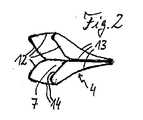
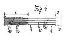
図1から7に示す捕獲器具は、捕獲構造1を有しており、その捕獲構造は、図4に展開して示すチューブセクション2からスリットを形成して曲げ広げることによって一体的に形成されている。捕獲構造1は、近位のスリットのないベース部分3と、それから軸方向前方へ延びる遠位の捕獲部分4とを有している。 The capture device shown in FIGS. 1 to 7 has a capture structure 1, which is integrally formed by forming a slit from the tube section 2 shown in FIG. Yes. The capture structure 1 has a proximal slit-
捕獲構造1は、その近位の終端領域において引っ張りワイヤと称される操作部材5によって遠位の終端領域と結合されており、その操作部材は被覆6内で軸方向に移動可能に案内されている。結合は、好ましくは、たとえば接着又は溶接結合によって、捕獲構造1の近位の終端部分がそのままで、軸方向に移動しないように操作部材5の遠位の終端領域と結合されることによって、実現されている。それによって捕獲構造1は、操作部材5の然るべき軸方向の操作運動によって軸方向前方へも、軸方向後方へも移動することができる。引っ張りワイヤ5と被覆6は、好ましくは弾性的に撓むことができる材料から形成されている。図1において捕獲構造1は、捕獲位置で示されており、その捕獲位置において捕獲構造は被覆6から完全に前方へ出るように移動されており、かつ捕獲部分4が完全に広げられた状態をとっている。引っ張りワイヤ5を引き戻し、及び/又は被覆6を押し出すために、捕獲構造1は被覆6内へ完全に引き込むことができ、その場合にその捕獲部分4がたたみ込まれ、すなわち被覆6の内径までたたみ込まれる。捕獲部分4は、この完全にたたみ込まれた位置において、大体において図4に示す、チューブセクション3にスリットを形成して曲げ広げる前に存在するような、形状をとる。捕獲構造1を得るためにチューブセクション3にスリットを形成して曲げ広げるための技術は、当業者には周知である。捕獲構造1のために、それに適した材料が使用され、その材料は弾性的に曲がって広がり、かつ粘結又は硬化のような処理プロセスによって弾性的に曲げ広げた状態に固定される。そのためにたとえば、NiTi合金のような、超弾性的な材料が一般に用いられる。 The capture structure 1 is connected in its proximal end region to a distal end region by means of an operating member 5 called a pull wire, which is guided in an axially movable manner in the
特に図1から3に明らかなように、捕獲部分4は展開された状態において遠位の捕獲開口部7を備えたゴブレット構造を有しており、その捕獲開口部が同時に捕獲構造1の最大の開口幅を表す。したがってこの捕獲器具は医療用の適用においては、たとえば石捕獲器具として、患者の身体組織内の石又は粒子を前から捕獲部分4内へ捕獲するために用いられる。これがこの器具を従来の捕獲バスケット構造から区別し、その従来のものにおいては粒子が器具長手軸に対して横方向に、すなわち径方向に、前と後ろがほぼ閉鎖したワイヤバスケット内へ捕獲される。 As can be seen in particular in FIGS. 1 to 3, the capture part 4 has a goblet structure with a
図3は、粒子8、たとえば腎石を前から捕獲開口部7を通して器具及びそれに伴ってゴブレット形状の捕獲部分4の長手軸線9に対して平行に近位方向Pに、このように捕獲することを示している。これが、前方と後方が閉鎖した捕獲バスケットを有する器具に比較して捕獲プロセスを容易にすることができる。というのは、捕獲プロセスのために器具は、第1に軸方向のみに移動させればよく、横方向に移動させる必要がないからである。さらに、これは、粒子が軸方向においてその後ろに位置する脈管壁のすぐ前にある場合に、粒子の捕獲を容易にすることができる。 FIG. 3 shows that particles 8, such as nephrolith, are thus captured in the proximal direction P parallel to the longitudinal axis 9 of the instrument and concomitantly the goblet-shaped capture part 4 through the
特に図2と4から明らかなように、チューブセクション2はスリットを形成する場合に特殊なスリット構造を設けられ、そのスリット構造は遠位のチューブセクション端部において開放して開口するスリット10と、距離をおいて遠位のチューブセクション端部の前で終了する、中間に位置する閉鎖された軸方向のスリット11とを有している。閉鎖された軸方向のスリット11は、遠位の開放したスリット10を越えて近位方向に後方へ延びている。このスリット構造によって、該当する遠位のチューブセクション部分から、第1の前方のワイヤセクション12と第2の後方のワイヤセクション13が形成されている。その場合に前方のワイヤセクション12は、開放したスリット10と閉鎖されたスリット11が重なり合う軸方向の領域内にあり、その場合に開放したスリット10と閉鎖されたスリット11は周方向に交代する。後方のワイヤセクション13は、閉鎖されたスリット11が開放したスリット10を越えて近位に延びる軸方向の領域内にある。その場合に移行領域において、各後方のワイヤセクション13が2つの前方のワイヤセクション12に分岐する。 2 and 4, the tube section 2 is provided with a special slit structure when forming a slit, which slit structure is open and open at the distal tube section end; With a closed axial slit 11 located in the middle, ending in front of the distal tube section end at a distance. A closed axial slit 11 extends rearward in the proximal direction beyond the distal
閉鎖されたスリット11が遠位のチューブセクション端部の前で終了する間隔が、湾曲したワイヤセクション領域12aのワイヤセクション幅bDを定め、その間隔を介して各前方のワイヤセクション12が隣接する前方のワイヤセクション12と遠位で関わり合う。図示の例においては半円形状に湾曲したこのワイヤ結合領域12aの幅bDは、たとえば、図5から明らかなように、それと結合された前方のワイヤセクション12の幅にほぼ相当することができる。さらに図5から明らかなように、この湾曲したワイヤ結合領域12aの曲率半径RDは、ワイヤ結合領域12aの直径もしくは幅bDよりもずっと大きい。然るべきスリット形成によって、この距離半径RDはこのワイヤセクション幅bDの少なくとも2.5倍、すなわちRD≧2.5xbDである。その結果、スリットを形成されたチューブセクションを捕獲部分4のゴブレット形状へ曲げ広げる場合に、前方のチューブセクション12はその湾曲した結合領域12a内で、ワイヤ結合領域12a内の破断の危険なしに、比較的大きくなる場合のある所望の曲げ広げ角度まで曲げ広げることができ、その場合に必要に応じて、捕獲構造1のために遠位の方向に鋭く近づくように延びる各終端構造が回避される。図6は、結合領域12aを介して結合された2つのワイヤセクション12をその破線で示す平行な初期位置から180°曲げ広げられた位置へ曲げ広げる例を示している。The spacing at which the closed slit 11 ends in front of the distal tube section end defines the wire section width bD of the curved
チューブセクション2の上述したスリット構造によって、捕獲部分4が所望のように遠位の捕獲開口部7を有する上述したゴブレット形状に曲げ広げられる。その場合に、図2から明らかなように、後方のワイヤセクション13がゴブレット本体を、そして前方のワイヤセクション12が捕獲ゴブレット4の周端縁14、すなわち遠位の捕獲開口部7の端縁、を形成する。したがって前方のワイヤセクション12の長さ及びその数が、捕獲ゴブレット4の遠位の端縁の最大の長さを定め、もしくは形成する。換言すると、図4に示すように、遠位の開放したスリット10がチューブセクション2に適切な長さLで形成され、その長さは、捕獲部分4を所望のゴブレット形状に曲げ広げることができるように選択されており、その場合にゴブレット端縁及びそれに伴って流入開口部7の実効進入横断面の周囲も、開放したスリット10及びそれに伴って前方のワイヤセクション12のこの長さLにより、かつ前方のワイヤセクション12がそのワイヤ結合領域12aにおいて曲げ広げられる寸法によって定められる。 The above-described slit structure of the tube section 2 causes the capture portion 4 to bend and expand into the above-described goblet shape with the
図4に示す例において、スリット構造はそれぞれ4つの遠位の開放したスリット12と4つの閉鎖したスリット11を有し、したがって4つの数nの後方のワイヤセクション11と2倍の8つの数2nの前方のワイヤセクション12を有している。なお、本発明の代替的な変形例において、任意の数nの閉鎖された、もしくは遠位の開放したスリットを設けることができ、すなわち数nは1より大きい任意の整数とすることができる。 In the example shown in FIG. 4, the slit structure has four distal
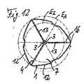
上述した寸法比率は、図7に示すような、捕獲ゴブレット4もしくはその捕獲開口部7の上面図を用いて説明される。図7の例の開放又は閉鎖したパイプスリットの数n=4及びそれに伴って4つの後方のワイヤセクション11の数n=4と8つの前方のワイヤセクション12の2倍の数2n=8から明らかなように、ゴブレット端縁4は、8つの前方のワイヤセクション12にその4つの結合領域12aを加えて形成される。したがってこのゴブレット端縁の長さは大体において、前方のワイヤセクション12の長さLの約8倍に、それに対してずっと小さい大きさの4つのワイヤ結合領域12aを加えたものとなる。ゴブレット端縁14は、軸方向に投影して、内円EIと外円EAとの間に位置し、その場合に外円EAが捕獲ゴブレット4の外径を定め、内円EIが捕獲開口部円を表し、その捕獲開口部円はゴブレット端縁14に縁取られた捕獲開口部7を近似的に良好に表している。The dimensional ratio described above will be described using a top view of the capture goblet 4 or its
前方のワイヤセクション12がそのワイヤ結合領域12aにおいて、図6の例におけるように、約180°曲げ広げられた場合に、ほぼ平面内に位置するゴブレット端縁4が生じ、かつゴブレット端縁4の周囲の長さは捕獲開口部円EIの周囲の長さUよりわずかに大きいだけであって、その周囲の長さはその半径REからU=2πREの関係によって定められる。換言すると、この実効捕獲開口部円EIの周囲の長さUは、ゴブレット端縁4の実際の周囲の長さよりわずかに小さいだけであって、この実際の周囲の長さは、チューブセクション2から形成されたワイヤセクション12、13の軸方向の開放したスリット10と閉鎖したスリット11の数2nを開放した軸方向のスリット10の長さLで乗算した積2nLにワイヤ結合領域12aによる長さを加えたものによって与えられる。When the
したがって遠位の開放したスリット10の充分に大きい長さLを選択することによって、所望の大きさの捕獲横断面を有する捕獲開口部7が準備される。前方のワイヤセクション12がそのワイヤ結合領域12aにおいて180°より小さい角度だけ曲げ広げられた場合には、より小さい曲げ広げ角度によってゴブレット端縁4の波形の推移が生じ、それによってゴブレット端縁長さは実効捕獲開口部円EIの周囲の長さUに比較して幾分増大する。好ましい実施形態において、捕獲開口部円EIの周囲の長さUは、前方のワイヤセクション12の数2nとその長さLの積2nLの少なくとも70%の値に維持される。それによって比較的大きい捕獲開口部7と適度に波打ったゴブレット端縁14の推移とを有する捕獲部分4の好ましいゴブレット形状がもたらされる。Accordingly, by selecting a sufficiently large length L of the distal
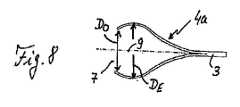
捕獲ゴブレット4のために、スリットを形成された遠位のチューブセクション領域内へ曲げ広げるために挿入される適切な曲げ型を使用することによって、任意の所望の形状が実現される。図8から10は、3つの代表的な例を示している。図8の実施変形例においては、捕獲構造は捕獲部分4aを有しており、その捕獲部分はベース部分3から遠位の方向へ拡幅がだんだんと少なく、すなわち線形より弱くなっている。その場合に捕獲領域は、遠位の捕獲開口部7の前に距離をおいて最大の直径DEもしくは横断面を占め、そこから捕獲開口部7の幾分小さい直径DOもしくは横断面へ狭まっている。捕獲ゴブレット4aの遠位の狭まりは、捕獲した対象の確実な保持を支援することができる。For the capture goblet 4, any desired shape is achieved by using a suitable bending mold that is inserted to bend and spread into the slit formed distal tube section region. 8 to 10 show three typical examples. In the embodiment variant of FIG. 8, the capture structure has a capture portion 4a, which is gradually less widened in the distal direction from the
図9に示す変形例においては、捕獲ゴブレット4bは、ベース部分3から遠位の方向へその拡幅直径を線形に増大させながら延びている。図10に示す実施変形例においては、捕獲ゴブレット4cは、ベース部分3から始まって遠位の方向へ漸増的に、すなわち線形より強くその直径を増大させながら延びている。なお、図9と10のゴブレット変形例も、捕獲ゴブレット7が被覆6内へ引き戻されて、そのゴブレットワイヤ構造がたたみ込みによって引き絞られて捕獲された対象にぴったり添接し、その対象を静止摩擦力によって前へ滑り抜けないようにすることによって、捕獲した対象の確実な保持を可能にする。 In the modification shown in FIG. 9, the capture goblet 4 b extends from the
図11から16は、本発明に係る捕獲器具の好ましい形態を示しており、その形態は特にMR適用に適しており、かつこの目的のためにそれ自体知られたやり方でMRマーカー材料が設けられている。それについて図11が示す例においては、捕獲構造1は、捕獲構造1のコーティングされた外側面の破線で示唆されるように、全面をMEコーティング材料15によってコーティングされている。 FIGS. 11 to 16 show a preferred form of the capture device according to the invention, which form is particularly suitable for MR applications and is provided with MR marker material in a manner known per se for this purpose. ing. In the example shown in FIG. 11, the capture structure 1 is coated on the entire surface with the
図11の例において、捕獲ゴブレット4は、捕獲端縁14を捕獲ゴブレット4の実効捕獲開口部円EIと外円EAに関して寸法設計するための然るべき順序で、3つの後方のワイヤセクション13とそれに応じて6つの前方のワイヤセクション12によって形成されており、それは、図7の実施例についてn=4の後方と8つの前方のワイヤセクションの場合について説明したのと同様であって、それを参照することができる。In the example of FIG. 11, the capture goblet 4 has three
図12は、図11の実施例の変形を示しており、それにおいて、捕獲構造1の部分面の領域と点状の領域にMRマーキング材料16が設けられている。図13の詳細な図が、互いに間隔をもって相前後して配置された細長いMRマーカー細片16aの列による、後方のワイヤセクション13の部分面のコーティングを示している。その代わりに、あるいはそれに加えて然るべきMRマーカー細片を前方のワイヤセクション12に設けることができる。図14は、詳細な図において、点状のMRマーカースポット16bを示しており、そのマーカースポットはそれぞれ、後方のワイヤセクション13が2つの前方のワイヤセクション12へ分岐する分岐箇所の領域に設けられている。 FIG. 12 shows a variant of the embodiment of FIG. 11, in which
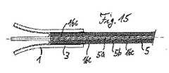
図15は、引っ張りワイヤ5がワイヤコア5aとそれを包囲するコアカバー5bとによって形成される実施変形例を示しており、その場合にMRマーカー材料からなるリング16cが互いに軸方向の間隔をもってワイヤコア5a上に設けられて、カバー5bによって埋め込まれている。図16に示す実施変形例において、チューブ形状の被覆6に軸方向に延びるライン形状のMRマーカー材料16dが設けられており、そのチューブ状の被覆内に引っ張りワイヤ5が軸方向に移動可能に案内されている。なお、図11から16で説明されている、捕獲器具にMR適用のために所望のMR視認を準備する措置は、任意のやり方で互いに組み合わせることができる。 FIG. 15 shows an embodiment in which the pulling wire 5 is formed by a wire core 5a and a core cover 5b surrounding the wire core 5a, in which case the rings 16c made of MR marker material are spaced apart from each other in the axial direction by the wire core 5a. It is provided above and is embedded by the cover 5b. In the embodiment shown in FIG. 16, the tube-shaped
本発明の図示されない実施形態において、捕獲ゴブレットはそのゴブレット本体の領域内に、強く分岐した構造を有している。そのために、遠位で開放したスリットと、それらと軸方向に重なる閉鎖されたスリットの他に、チューブセクションに他の閉鎖されたスリットが形成されており、その場合に他の閉鎖されたスリットは、すでに述べた閉鎖されたスリットと軸方向に重なって、近位方向にそれらを越えて延びている。その場合に好ましくはここでも、他の閉鎖された軸方向のスリットが重なり領域内で他の閉鎖されたスリットと周方向に交代することができる。その場合には、ゴブレット本体の格子状に分岐した構造がもたらされる。 In an unillustrated embodiment of the invention, the capture goblet has a strongly branched structure within the region of the goblet body. For this purpose, in addition to the slits that are open at the distal end and the closed slits that overlap axially with them, other closed slits are formed in the tube section, in which case the other closed slits are , Which overlaps the previously described closed slit axially and extends beyond them in the proximal direction. Here again, preferably again, other closed axial slits can be replaced circumferentially with other closed slits in the overlap region. In that case, a goblet body branched structure is provided.
好ましい実施例についての上述した説明が明らかにするように、本発明は、特に医療用の捕獲構造として、たとえばMR適用においても使用され、かつ前側から異物、粒子などの確実な捕獲を許す、捕獲器具を提供する。その場合に捕獲構造は、製造技術的に好ましいやり方でチューブセクションから一体的に形成される。そのために溶接箇所のようなワイヤ結合をわざわざ形成する必要はない。したがって該当する溶接箇所又は接着箇所あるいは他の何らかの結合箇所の破断又は他の不具合を伴う問題が生じることはない。 As the above description of the preferred embodiment reveals, the present invention is particularly used as a medical capture structure, for example in MR applications, and also allows capture of foreign objects, particles, etc. from the front side. Provide equipment. In that case, the capture structure is integrally formed from the tube section in a manner that is preferred in terms of manufacturing technology. Therefore, it is not necessary to bother to form a wire connection such as a welded part. Therefore, there will be no problem with breakage or other problems at the relevant welded or bonded locations or any other joint location.
Claims (7)
Translated fromJapanese−チューブセクション(2)からスリットを設けて曲げ広げることによって一体的に形成された捕獲構造(1)を有し、前記捕獲構造が、近位のベース部分(3)と、近位のベース部分(3)から軸方向前方へ延びる遠位の捕獲部分(4)と、を有し、また、前記捕獲構造が、捕獲部分が拡げられて被覆(6)から出て前方へ移動した捕獲位置と、前記捕獲部分がしっかりとたたみ込まれて被覆内へ戻るように移動した固持位置と、の間で移動可能である、捕獲器具において、
−前記捕獲部分(4)が、広げられた状態において、遠位の捕獲開口部(7)を備えたゴブレット形状を有し、この構成のために、チューブセクション(2)の遠位の端部領域には、チューブセクションの遠位端部の方向から形成された、適切な長さの複数の開放した軸方向のスリット(10)、が設けられており、前記複数の開放した軸方向のスリットの間には、複数の閉鎖された軸方向のスリット(11)が設けられており、
前記複数の閉鎖された軸方向のスリット(11)は、チューブセクションの遠位端部の前で距離をおいて終了し、前記開放した軸方向のスリットよりも長さが長く、前記開放した軸方向のスリットと閉鎖された軸方向のスリットとによって、ワイヤセクション(12)が、チューブセクションから形成されており、前記チューブセクションを曲げ広げることによって、前記ワイヤセクション(12)が、前記捕獲開口部の周囲部分を形成する、
ことを特徴とする、
捕獲器具。A capture device, in particular a medical capture device,
-Having a capture structure (1) integrally formed by slitting and expanding from the tube section (2), said capture structure comprising a proximal base portion (3) and a proximal base portion; A distal capture portion (4) extending axially forward from (3), and the capture structure has a capture position in which the capture portion has been expanded and moved forward out of the covering (6) A capture device that is movable between a capture position in which the capture portion is tightly folded and moved back into the coating;
The capture portion (4) has, in the unfolded state, a goblet shape with a distal capture opening (7), for this configuration the distal end of the tube section (2) The region is provided with a plurality of open axial slits (10) of appropriate length formed from the direction of the distal end of the tube section, the plurality of open axial slits. In between there are a plurality of closed axial slits (11),
The plurality of closed axial slits (11) terminate at a distance in front of the distal end of the tube section and are longer in length than the open axial slit, the open shaft A wire section (12) is formed from the tube section by a directional slit and a closed axial slit, and by bending and unfolding the tube section, the wire section (12) is Forming the surrounding part of the
It is characterized by
Capture device.
請求項1に記載の捕獲器具。Furthermore, two adjacent wire sections formed by an axially open and closed slit from the tube section are connected to each other via a curved region (12a), the radius of said curved region (RD ) is at least 2.5 times as large as the width (bD ) of the wire section in the curved region,
The capture device according to claim 1.
請求項1又は2に記載の捕獲器具。In addition, the effective capture opening circle perimeter length opened the number (2n) of wire sections (12) formed by the axially open and closed slits from the tube section. 70% or more of the product (2nL) multiplied by the length (L) of the slit in the axial direction,
The capture device according to claim 1 or 2.
請求項1から3のいずれか1項に記載の捕獲器具。Further, the goblet shape of the capture portion has one or more regions in the unfolded state, within which the diameter of the goblet increases linearly or incrementally in a distal direction. Or an increase in the diameter of the goblet gradually decreases in the distal direction,
The capturing device according to any one of claims 1 to 3.
請求項1から4のいずれか1項に記載の捕獲器具。Furthermore, the maximum diameter (DE ) of the goblet shape of the capture part is larger than the diameter (DO ) of the capture opening in the expanded state,
The capturing device according to any one of claims 1 to 4.
請求項1から5のいずれか1項に記載の捕獲器具。In addition, the capture portion has a second closed axial slit in the tube section, the second closed axial slit extending forwardly to the distal end, Extending between the distal and proximal ends of the one closed axial slit and back to the proximal end of the first closed axial slit. Extending to the rear of the proximal end, characterized in that
The capturing device according to any one of claims 1 to 5.
請求項1から6のいずれか1項に記載の捕獲器具。Furthermore, the capture structure and / or the covering (6) and / or the pulling wire (5) for the capturing structure, which is guided axially movable in the covering, can be entirely or partially Alternatively, a magnetic resonance (MR) marking material (16a, 16b, 16c, 16d) is provided in the form of dots.
The capturing device according to any one of claims 1 to 6.
Applications Claiming Priority (3)
| Application Number | Priority Date | Filing Date | Title |
|---|---|---|---|
| DE102014205366.8ADE102014205366B4 (en) | 2014-03-21 | 2014-03-21 | Catch wire instrument with catch wire structure made of tubular piece |
| DE102014205366.8 | 2014-03-21 | ||
| PCT/EP2015/054894WO2015139998A1 (en) | 2014-03-21 | 2015-03-10 | Snare instrument with snare structure composed of a tubular piece |
Publications (2)
| Publication Number | Publication Date |
|---|---|
| JP2017512574Atrue JP2017512574A (en) | 2017-05-25 |
| JP6549609B2 JP6549609B2 (en) | 2019-07-24 |
Family
ID=52649017
Family Applications (1)
| Application Number | Title | Priority Date | Filing Date |
|---|---|---|---|
| JP2016559248AActiveJP6549609B2 (en) | 2014-03-21 | 2015-03-10 | A capture device having a capture structure consisting of tube sections |
Country Status (6)
| Country | Link |
|---|---|
| US (1) | US10478203B2 (en) |
| EP (1) | EP3119292B1 (en) |
| JP (1) | JP6549609B2 (en) |
| CN (1) | CN106456199B (en) |
| DE (1) | DE102014205366B4 (en) |
| WO (1) | WO2015139998A1 (en) |
Families Citing this family (7)
| Publication number | Priority date | Publication date | Assignee | Title |
|---|---|---|---|---|
| DE102014208168A1 (en) | 2014-04-30 | 2015-11-19 | Epflex Feinwerktechnik Gmbh | Fangkelinstrument with distal Fangkelchstruktur |
| DE102017205725B4 (en) | 2017-04-04 | 2018-12-06 | Epflex Feinwerktechnik Gmbh | Medical claw instrument |
| EP4368156A3 (en) | 2017-11-09 | 2024-11-06 | ConvaTec Technologies Inc. | Ostomy monitoring system and method |
| USD893514S1 (en) | 2018-11-08 | 2020-08-18 | 11 Health And Technologies Limited | Display screen or portion thereof with graphical user interface |
| US12357494B2 (en) | 2020-10-15 | 2025-07-15 | Convatec Technologies Inc. | Ostomy systems and methods |
| KR102528715B1 (en)* | 2020-10-28 | 2023-05-04 | 사회복지법인 삼성생명공익재단 | Medical snare apparatus |
| DE102023109898A1 (en) | 2023-04-19 | 2024-10-24 | EPflex Feinwerktechnik GmbH. | Medical guidewire with twisted core wire |
Citations (7)
| Publication number | Priority date | Publication date | Assignee | Title |
|---|---|---|---|---|
| JP2005515830A (en)* | 2002-01-25 | 2005-06-02 | アトリテック, インコーポレイテッド | Atrial appendage blood filtration system |
| JP2007518516A (en)* | 2004-01-22 | 2007-07-12 | レックス メディカル リミテッド パートナーシップ | Vein filter |
| US20080311318A1 (en)* | 2004-11-08 | 2008-12-18 | Epflex Feinwerktechnik Gmbh | Multiwire Unit and Method for Producing the Same |
| US20090192485A1 (en)* | 2008-01-28 | 2009-07-30 | Heuser Richard R | Snare device |
| WO2013179137A2 (en)* | 2012-05-31 | 2013-12-05 | Javelin Medical Ltd. | Systems, methods and devices for embolic protection |
| WO2014008460A2 (en)* | 2012-07-05 | 2014-01-09 | Cognition Medical Corp. | Methods, devices, and systems for postconditioning with clot removal |
| JP2014533970A (en)* | 2011-11-09 | 2014-12-18 | ボストン サイエンティフィック サイムド,インコーポレイテッドBoston Scientific Scimed,Inc. | Occlusion device |
Family Cites Families (17)
| Publication number | Priority date | Publication date | Assignee | Title |
|---|---|---|---|---|
| DE19722429A1 (en) | 1997-05-28 | 1998-12-03 | Optimed Medizinische Instr Gmb | Capturing or reducing gall stones and kidney stones in hollow organs |
| WO2002078632A2 (en) | 2001-04-02 | 2002-10-10 | Acmi Corporation | Retrieval basket for a surgical device and system and method for manufacturing same |
| US7101379B2 (en) | 2001-04-02 | 2006-09-05 | Acmi Corporation | Retrieval basket for a surgical device and system and method for manufacturing same |
| US7063707B2 (en)* | 2002-03-06 | 2006-06-20 | Scimed Life Systems, Inc. | Medical retrieval device |
| US20030187495A1 (en) | 2002-04-01 | 2003-10-02 | Cully Edward H. | Endoluminal devices, embolic filters, methods of manufacture and use |
| WO2004100772A2 (en)* | 2003-05-12 | 2004-11-25 | University Of Florida | Devices and methods for disruption and removal of luninal occlusions |
| US7744604B2 (en) | 2003-11-13 | 2010-06-29 | Lawrence Livermore National Security, Llc | Shape memory polymer medical device |
| US7704266B2 (en) | 2004-01-22 | 2010-04-27 | Rex Medical, L.P. | Vein filter |
| US7166846B2 (en)* | 2004-06-30 | 2007-01-23 | Siemens Medical Solutions Usa, Inc. | Multi-pinhole collimation for nuclear medical imaging |
| US9655633B2 (en)* | 2004-09-10 | 2017-05-23 | Penumbra, Inc. | System and method for treating ischemic stroke |
| ATE480206T1 (en)* | 2006-03-03 | 2010-09-15 | Prescient Medical Inc | ENDOLUMINAL PROSTHESIS FOR THE TREATMENT OF SENSITIVE PLAQUE |
| US10123803B2 (en)* | 2007-10-17 | 2018-11-13 | Covidien Lp | Methods of managing neurovascular obstructions |
| EP2052688B1 (en)* | 2007-10-25 | 2012-06-06 | pfm medical ag | Snare mechanism for surgical retrieval |
| CN102186427B (en)* | 2008-09-22 | 2013-12-18 | 浩特斯博尔技术公司 | flow recovery system |
| US20120116496A1 (en)* | 2010-11-05 | 2012-05-10 | Chuter Timothy A | Stent structures for use with valve replacements |
| US8469970B2 (en)* | 2011-07-11 | 2013-06-25 | Great Aspirations Ltd. | Apparatus for entrapping and extracting objects from body cavities |
| US20130289578A1 (en)* | 2012-04-13 | 2013-10-31 | Yawa-Med, Inc. | Blood clot extraction device |
- 2014
- 2014-03-21DEDE102014205366.8Apatent/DE102014205366B4/enactiveActive
- 2015
- 2015-03-10CNCN201580025972.9Apatent/CN106456199B/ennot_activeExpired - Fee Related
- 2015-03-10EPEP15709151.3Apatent/EP3119292B1/enactiveActive
- 2015-03-10JPJP2016559248Apatent/JP6549609B2/enactiveActive
- 2015-03-10USUS15/127,501patent/US10478203B2/enactiveActive
- 2015-03-10WOPCT/EP2015/054894patent/WO2015139998A1/enactiveApplication Filing
Patent Citations (7)
| Publication number | Priority date | Publication date | Assignee | Title |
|---|---|---|---|---|
| JP2005515830A (en)* | 2002-01-25 | 2005-06-02 | アトリテック, インコーポレイテッド | Atrial appendage blood filtration system |
| JP2007518516A (en)* | 2004-01-22 | 2007-07-12 | レックス メディカル リミテッド パートナーシップ | Vein filter |
| US20080311318A1 (en)* | 2004-11-08 | 2008-12-18 | Epflex Feinwerktechnik Gmbh | Multiwire Unit and Method for Producing the Same |
| US20090192485A1 (en)* | 2008-01-28 | 2009-07-30 | Heuser Richard R | Snare device |
| JP2014533970A (en)* | 2011-11-09 | 2014-12-18 | ボストン サイエンティフィック サイムド,インコーポレイテッドBoston Scientific Scimed,Inc. | Occlusion device |
| WO2013179137A2 (en)* | 2012-05-31 | 2013-12-05 | Javelin Medical Ltd. | Systems, methods and devices for embolic protection |
| WO2014008460A2 (en)* | 2012-07-05 | 2014-01-09 | Cognition Medical Corp. | Methods, devices, and systems for postconditioning with clot removal |
Also Published As
| Publication number | Publication date |
|---|---|
| EP3119292A1 (en) | 2017-01-25 |
| CN106456199A (en) | 2017-02-22 |
| EP3119292B1 (en) | 2023-08-16 |
| US20170143357A1 (en) | 2017-05-25 |
| DE102014205366A1 (en) | 2015-09-24 |
| DE102014205366B4 (en) | 2019-03-28 |
| JP6549609B2 (en) | 2019-07-24 |
| CN106456199B (en) | 2019-01-01 |
| EP3119292C0 (en) | 2023-08-16 |
| WO2015139998A1 (en) | 2015-09-24 |
| US10478203B2 (en) | 2019-11-19 |
Similar Documents
| Publication | Publication Date | Title |
|---|---|---|
| JP2017512574A (en) | Capture device having a capture structure comprising a tube section | |
| US10939932B1 (en) | Expandable surgical devices and methods for making and using them | |
| CN105828730B (en) | Medical retrieval device and method | |
| JP7183153B2 (en) | Methods and apparatus for stent delivery | |
| JP7012114B2 (en) | IVC filter recovery system with releasable capture feature | |
| JP6251184B2 (en) | Recovery snare device and method | |
| JP4932822B2 (en) | Intravascular filter with centering member | |
| US8795317B2 (en) | Embolic obstruction retrieval devices and methods | |
| US10548706B2 (en) | Retrieval snare device and method | |
| EP2515991B1 (en) | Thrombus removal device and system | |
| JP5945119B2 (en) | Apparatus and method for improved stent deployment | |
| US20090221967A1 (en) | Intravascular Device | |
| AU2018220002B2 (en) | Distal capture device for a self-expanding stent | |
| US20190262026A1 (en) | Flexible three-arm snare structure and a method of using the flexible three-arm snare structure to retrieve stones from a human body | |
| US20180271546A1 (en) | Medical Catching-Wire Instrument | |
| CN107427311B (en) | Retrieval device and related method of use | |
| US9452039B2 (en) | Vascular filter | |
| JP4423382B2 (en) | Biological duct insertion wire | |
| JP6188997B1 (en) | Endoscopic treatment tool | |
| JP7636329B2 (en) | Devices, systems and methods for removing vascular obstructions - Patents.com | |
| JP6899482B2 (en) | Universal recovery device for removing obstacles from the body cavity |
Legal Events
| Date | Code | Title | Description |
|---|---|---|---|
| A621 | Written request for application examination | Free format text:JAPANESE INTERMEDIATE CODE: A621 Effective date:20180129 | |
| A711 | Notification of change in applicant | Free format text:JAPANESE INTERMEDIATE CODE: A711 Effective date:20181003 | |
| A521 | Request for written amendment filed | Free format text:JAPANESE INTERMEDIATE CODE: A821 Effective date:20181003 | |
| A131 | Notification of reasons for refusal | Free format text:JAPANESE INTERMEDIATE CODE: A131 Effective date:20181120 | |
| A977 | Report on retrieval | Free format text:JAPANESE INTERMEDIATE CODE: A971007 Effective date:20181122 | |
| A521 | Request for written amendment filed | Free format text:JAPANESE INTERMEDIATE CODE: A523 Effective date:20190214 | |
| A131 | Notification of reasons for refusal | Free format text:JAPANESE INTERMEDIATE CODE: A131 Effective date:20190226 | |
| A521 | Request for written amendment filed | Free format text:JAPANESE INTERMEDIATE CODE: A523 Effective date:20190515 | |
| TRDD | Decision of grant or rejection written | ||
| A01 | Written decision to grant a patent or to grant a registration (utility model) | Free format text:JAPANESE INTERMEDIATE CODE: A01 Effective date:20190528 | |
| A61 | First payment of annual fees (during grant procedure) | Free format text:JAPANESE INTERMEDIATE CODE: A61 Effective date:20190627 | |
| R150 | Certificate of patent or registration of utility model | Ref document number:6549609 Country of ref document:JP Free format text:JAPANESE INTERMEDIATE CODE: R150 | |
| R250 | Receipt of annual fees | Free format text:JAPANESE INTERMEDIATE CODE: R250 | |
| R250 | Receipt of annual fees | Free format text:JAPANESE INTERMEDIATE CODE: R250 | |
| R250 | Receipt of annual fees | Free format text:JAPANESE INTERMEDIATE CODE: R250 | |
| R250 | Receipt of annual fees | Free format text:JAPANESE INTERMEDIATE CODE: R250 |