JP2017510391A - Telescopic drive mechanism - Google Patents
Telescopic drive mechanismDownload PDFInfo
- Publication number
- JP2017510391A JP2017510391AJP2016567160AJP2016567160AJP2017510391AJP 2017510391 AJP2017510391 AJP 2017510391AJP 2016567160 AJP2016567160 AJP 2016567160AJP 2016567160 AJP2016567160 AJP 2016567160AJP 2017510391 AJP2017510391 AJP 2017510391A
- Authority
- JP
- Japan
- Prior art keywords
- drive
- tube
- assembly
- outer tube
- cartridge
- Prior art date
- Legal status (The legal status is an assumption and is not a legal conclusion. Google has not performed a legal analysis and makes no representation as to the accuracy of the status listed.)
- Withdrawn
Links
- 230000007246mechanismEffects0.000titledescription16
- 230000005540biological transmissionEffects0.000claimsabstractdescription27
- 239000003814drugSubstances0.000claimsdescription18
- 238000012377drug deliveryMethods0.000claimsdescription18
- 229940079593drugDrugs0.000claimsdescription16
- 230000008878couplingEffects0.000claimsdescription10
- 238000010168coupling processMethods0.000claimsdescription10
- 238000005859coupling reactionMethods0.000claimsdescription10
- 238000004891communicationMethods0.000claimsdescription3
- 239000012530fluidSubstances0.000claimsdescription3
- 238000013461designMethods0.000description8
- NOESYZHRGYRDHS-UHFFFAOYSA-NinsulinChemical compoundN1C(=O)C(NC(=O)C(CCC(N)=O)NC(=O)C(CCC(O)=O)NC(=O)C(C(C)C)NC(=O)C(NC(=O)CN)C(C)CC)CSSCC(C(NC(CO)C(=O)NC(CC(C)C)C(=O)NC(CC=2C=CC(O)=CC=2)C(=O)NC(CCC(N)=O)C(=O)NC(CC(C)C)C(=O)NC(CCC(O)=O)C(=O)NC(CC(N)=O)C(=O)NC(CC=2C=CC(O)=CC=2)C(=O)NC(CSSCC(NC(=O)C(C(C)C)NC(=O)C(CC(C)C)NC(=O)C(CC=2C=CC(O)=CC=2)NC(=O)C(CC(C)C)NC(=O)C(C)NC(=O)C(CCC(O)=O)NC(=O)C(C(C)C)NC(=O)C(CC(C)C)NC(=O)C(CC=2NC=NC=2)NC(=O)C(CO)NC(=O)CNC2=O)C(=O)NCC(=O)NC(CCC(O)=O)C(=O)NC(CCCNC(N)=N)C(=O)NCC(=O)NC(CC=3C=CC=CC=3)C(=O)NC(CC=3C=CC=CC=3)C(=O)NC(CC=3C=CC(O)=CC=3)C(=O)NC(C(C)O)C(=O)N3C(CCC3)C(=O)NC(CCCCN)C(=O)NC(C)C(O)=O)C(=O)NC(CC(N)=O)C(O)=O)=O)NC(=O)C(C(C)CC)NC(=O)C(CO)NC(=O)C(C(C)O)NC(=O)C1CSSCC2NC(=O)C(CC(C)C)NC(=O)C(NC(=O)C(CCC(N)=O)NC(=O)C(CC(N)=O)NC(=O)C(NC(=O)C(N)CC=1C=CC=CC=1)C(C)C)CC1=CN=CN1NOESYZHRGYRDHS-UHFFFAOYSA-N0.000description8
- 239000003795chemical substances by applicationSubstances0.000description5
- 102000004877InsulinHuman genes0.000description4
- 108090001061InsulinProteins0.000description4
- 229940125396insulinDrugs0.000description4
- 238000013519translationMethods0.000description4
- 101710198884GATA-type zinc finger protein 1Proteins0.000description2
- DTHNMHAUYICORS-KTKZVXAJSA-NGlucagon-like peptide 1Chemical compoundC([C@@H](C(=O)N[C@@H]([C@@H](C)CC)C(=O)N[C@@H](C)C(=O)N[C@@H](CC=1C2=CC=CC=C2NC=1)C(=O)N[C@@H](CC(C)C)C(=O)N[C@@H](C(C)C)C(=O)N[C@@H](CCCCN)C(=O)NCC(=O)N[C@@H](CCCNC(N)=N)C(N)=O)NC(=O)[C@H](CCC(O)=O)NC(=O)[C@H](CCCCN)NC(=O)[C@H](C)NC(=O)[C@H](C)NC(=O)[C@H](CCC(N)=O)NC(=O)CNC(=O)[C@H](CCC(O)=O)NC(=O)[C@H](CC(C)C)NC(=O)[C@H](CC=1C=CC(O)=CC=1)NC(=O)[C@H](CO)NC(=O)[C@H](CO)NC(=O)[C@@H](NC(=O)[C@H](CC(O)=O)NC(=O)[C@H](CO)NC(=O)[C@@H](NC(=O)[C@H](CC=1C=CC=CC=1)NC(=O)[C@@H](NC(=O)CNC(=O)[C@H](CCC(O)=O)NC(=O)[C@H](C)NC(=O)[C@@H](N)CC=1N=CNC=1)[C@@H](C)O)[C@@H](C)O)C(C)C)C1=CC=CC=C1DTHNMHAUYICORS-KTKZVXAJSA-N0.000description2
- 102400000322Glucagon-like peptide 1Human genes0.000description2
- 238000009472formulationMethods0.000description2
- 229940088597hormoneDrugs0.000description2
- 239000005556hormoneSubstances0.000description2
- 238000002347injectionMethods0.000description2
- 239000007924injectionSubstances0.000description2
- 238000003780insertionMethods0.000description2
- 230000037431insertionEffects0.000description2
- 239000007788liquidSubstances0.000description2
- 238000004519manufacturing processMethods0.000description2
- 238000000034methodMethods0.000description2
- 239000000203mixtureSubstances0.000description2
- 238000012544monitoring processMethods0.000description2
- 108090000623proteins and genesProteins0.000description2
- 238000007920subcutaneous administrationMethods0.000description2
- 208000032368Device malfunctionDiseases0.000description1
- 102000018997Growth HormoneHuman genes0.000description1
- 108010051696Growth HormoneProteins0.000description1
- 239000013543active substanceSubstances0.000description1
- -1analogs thereofChemical compound0.000description1
- 238000001514detection methodMethods0.000description1
- 206010012601diabetes mellitusDiseases0.000description1
- 239000000499gelSubstances0.000description1
- 230000014509gene expressionEffects0.000description1
- 239000000122growth hormoneSubstances0.000description1
- 230000002452interceptive effectEffects0.000description1
- 230000009191jumpingEffects0.000description1
- 238000010999medical injectionMethods0.000description1
- 235000016709nutritionNutrition0.000description1
- 239000002831pharmacologic agentSubstances0.000description1
- 102000004196processed proteins & peptidesHuman genes0.000description1
- 108090000765processed proteins & peptidesProteins0.000description1
- 102000004169proteins and genesHuman genes0.000description1
- 239000007787solidSubstances0.000description1
- 239000000243solutionSubstances0.000description1
- 230000005236sound signalEffects0.000description1
- 239000000126substanceSubstances0.000description1
- 239000000725suspensionSubstances0.000description1
Images


Classifications
- A—HUMAN NECESSITIES
- A61—MEDICAL OR VETERINARY SCIENCE; HYGIENE
- A61M—DEVICES FOR INTRODUCING MEDIA INTO, OR ONTO, THE BODY; DEVICES FOR TRANSDUCING BODY MEDIA OR FOR TAKING MEDIA FROM THE BODY; DEVICES FOR PRODUCING OR ENDING SLEEP OR STUPOR
- A61M5/00—Devices for bringing media into the body in a subcutaneous, intra-vascular or intramuscular way; Accessories therefor, e.g. filling or cleaning devices, arm-rests
- A61M5/178—Syringes
- A61M5/31—Details
- A61M5/315—Pistons; Piston-rods; Guiding, blocking or restricting the movement of the rod or piston; Appliances on the rod for facilitating dosing ; Dosing mechanisms
- A61M5/31565—Administration mechanisms, i.e. constructional features, modes of administering a dose
- A61M5/31576—Constructional features or modes of drive mechanisms for piston rods
- A61M5/31583—Constructional features or modes of drive mechanisms for piston rods based on rotational translation, i.e. movement of piston rod is caused by relative rotation between the user activated actuator and the piston rod
- A—HUMAN NECESSITIES
- A61—MEDICAL OR VETERINARY SCIENCE; HYGIENE
- A61M—DEVICES FOR INTRODUCING MEDIA INTO, OR ONTO, THE BODY; DEVICES FOR TRANSDUCING BODY MEDIA OR FOR TAKING MEDIA FROM THE BODY; DEVICES FOR PRODUCING OR ENDING SLEEP OR STUPOR
- A61M5/00—Devices for bringing media into the body in a subcutaneous, intra-vascular or intramuscular way; Accessories therefor, e.g. filling or cleaning devices, arm-rests
- A61M5/178—Syringes
- A61M5/31—Details
- A61M5/315—Pistons; Piston-rods; Guiding, blocking or restricting the movement of the rod or piston; Appliances on the rod for facilitating dosing ; Dosing mechanisms
- A61M5/31511—Piston or piston-rod constructions, e.g. connection of piston with piston-rod
- A—HUMAN NECESSITIES
- A61—MEDICAL OR VETERINARY SCIENCE; HYGIENE
- A61M—DEVICES FOR INTRODUCING MEDIA INTO, OR ONTO, THE BODY; DEVICES FOR TRANSDUCING BODY MEDIA OR FOR TAKING MEDIA FROM THE BODY; DEVICES FOR PRODUCING OR ENDING SLEEP OR STUPOR
- A61M5/00—Devices for bringing media into the body in a subcutaneous, intra-vascular or intramuscular way; Accessories therefor, e.g. filling or cleaning devices, arm-rests
- A61M5/178—Syringes
- A61M5/31—Details
- A61M5/315—Pistons; Piston-rods; Guiding, blocking or restricting the movement of the rod or piston; Appliances on the rod for facilitating dosing ; Dosing mechanisms
- A61M5/31533—Dosing mechanisms, i.e. setting a dose
- A61M5/31545—Setting modes for dosing
- A61M5/31548—Mechanically operated dose setting member
- A61M5/3155—Mechanically operated dose setting member by rotational movement of dose setting member, e.g. during setting or filling of a syringe
- F—MECHANICAL ENGINEERING; LIGHTING; HEATING; WEAPONS; BLASTING
- F16—ENGINEERING ELEMENTS AND UNITS; GENERAL MEASURES FOR PRODUCING AND MAINTAINING EFFECTIVE FUNCTIONING OF MACHINES OR INSTALLATIONS; THERMAL INSULATION IN GENERAL
- F16H—GEARING
- F16H25/00—Gearings comprising primarily only cams, cam-followers and screw-and-nut mechanisms
- F16H25/18—Gearings comprising primarily only cams, cam-followers and screw-and-nut mechanisms for conveying or interconverting oscillating or reciprocating motions
- F16H25/20—Screw mechanisms
- F16H25/2056—Telescopic screws with at least three screw members in coaxial arrangement
- A—HUMAN NECESSITIES
- A61—MEDICAL OR VETERINARY SCIENCE; HYGIENE
- A61M—DEVICES FOR INTRODUCING MEDIA INTO, OR ONTO, THE BODY; DEVICES FOR TRANSDUCING BODY MEDIA OR FOR TAKING MEDIA FROM THE BODY; DEVICES FOR PRODUCING OR ENDING SLEEP OR STUPOR
- A61M5/00—Devices for bringing media into the body in a subcutaneous, intra-vascular or intramuscular way; Accessories therefor, e.g. filling or cleaning devices, arm-rests
- A61M5/178—Syringes
- A61M5/31—Details
- A61M5/315—Pistons; Piston-rods; Guiding, blocking or restricting the movement of the rod or piston; Appliances on the rod for facilitating dosing ; Dosing mechanisms
- A61M5/31511—Piston or piston-rod constructions, e.g. connection of piston with piston-rod
- A61M2005/31518—Piston or piston-rod constructions, e.g. connection of piston with piston-rod designed to reduce the overall size of an injection device, e.g. using flexible or pivotally connected chain-like rod members
- A—HUMAN NECESSITIES
- A61—MEDICAL OR VETERINARY SCIENCE; HYGIENE
- A61M—DEVICES FOR INTRODUCING MEDIA INTO, OR ONTO, THE BODY; DEVICES FOR TRANSDUCING BODY MEDIA OR FOR TAKING MEDIA FROM THE BODY; DEVICES FOR PRODUCING OR ENDING SLEEP OR STUPOR
- A61M5/00—Devices for bringing media into the body in a subcutaneous, intra-vascular or intramuscular way; Accessories therefor, e.g. filling or cleaning devices, arm-rests
- A61M5/178—Syringes
- A61M5/31—Details
- A61M5/315—Pistons; Piston-rods; Guiding, blocking or restricting the movement of the rod or piston; Appliances on the rod for facilitating dosing ; Dosing mechanisms
- A61M5/31565—Administration mechanisms, i.e. constructional features, modes of administering a dose
- A61M5/31576—Constructional features or modes of drive mechanisms for piston rods
- A61M2005/31588—Constructional features or modes of drive mechanisms for piston rods electrically driven
- A—HUMAN NECESSITIES
- A61—MEDICAL OR VETERINARY SCIENCE; HYGIENE
- A61M—DEVICES FOR INTRODUCING MEDIA INTO, OR ONTO, THE BODY; DEVICES FOR TRANSDUCING BODY MEDIA OR FOR TAKING MEDIA FROM THE BODY; DEVICES FOR PRODUCING OR ENDING SLEEP OR STUPOR
- A61M2205/00—General characteristics of the apparatus
- A61M2205/50—General characteristics of the apparatus with microprocessors or computers
- A61M2205/502—User interfaces, e.g. screens or keyboards
- A—HUMAN NECESSITIES
- A61—MEDICAL OR VETERINARY SCIENCE; HYGIENE
- A61M—DEVICES FOR INTRODUCING MEDIA INTO, OR ONTO, THE BODY; DEVICES FOR TRANSDUCING BODY MEDIA OR FOR TAKING MEDIA FROM THE BODY; DEVICES FOR PRODUCING OR ENDING SLEEP OR STUPOR
- A61M2205/00—General characteristics of the apparatus
- A61M2205/58—Means for facilitating use, e.g. by people with impaired vision
- A61M2205/581—Means for facilitating use, e.g. by people with impaired vision by audible feedback
Landscapes
- Health & Medical Sciences (AREA)
- Engineering & Computer Science (AREA)
- Hematology (AREA)
- Anesthesiology (AREA)
- Biomedical Technology (AREA)
- Heart & Thoracic Surgery (AREA)
- Vascular Medicine (AREA)
- Life Sciences & Earth Sciences (AREA)
- Animal Behavior & Ethology (AREA)
- General Health & Medical Sciences (AREA)
- Public Health (AREA)
- Veterinary Medicine (AREA)
- General Engineering & Computer Science (AREA)
- Mechanical Engineering (AREA)
- Infusion, Injection, And Reservoir Apparatuses (AREA)
Abstract
Translated fromJapaneseDescription
Translated fromJapanese本発明は、一般に、伸縮式の駆動機構に関する。特定の態様では、本発明は、薬剤で充填されたカートリッジを受け入れ、その後に、カートリッジから用量を吐出するように適合されたモータ駆動の薬剤送達装置に組み込まれた駆動機構に関する。 The present invention generally relates to a telescopic drive mechanism. In a particular aspect, the present invention relates to a drive mechanism incorporated into a motor-driven drug delivery device adapted to receive a drug-filled cartridge and subsequently dispense a dose from the cartridge.
本発明の開示においては、主として、個別に、または連続して行われる皮下薬剤送達による糖尿病の治療用として意図された薬剤送達装置に対して参照が行われるが、これは、本発明の例示的な使用に過ぎない。 In the disclosure of the present invention, reference will be made primarily to drug delivery devices intended for the treatment of diabetes by individual or sequential subcutaneous drug delivery, which is illustrative of the present invention. Only use.
薬剤で充填されたカートリッジを受け入れ、かつカートリッジから所望するサイズの個別の用量を吐出するように適合された最も一般的なタイプの耐久性のある薬剤送達装置は、手動手段により、または用量設定中に付勢されたばねにより駆動され、カートリッジは、初期の近位の位置を有し、かつピストンロッドにより遠位方向に移動される軸方向に変位可能なピストンを備えるタイプのものである。皮下薬剤送達は、カートリッジと流体連通状態に構成された注射針により行われる。装置は、ペン形状、またはより箱型のいわゆるドーザ(doser)の形態とすることができる。利便性、ユーザの使いやすさを改良するために、かつ例えば、吐出データを検出および記憶するなどさらなる機能を提供するために、薬剤送達装置は、例えば、米国特許第6,514,230号、および米国特許出願公開第2011/306927号で示されるものなど、通常、歯車機構を介してピストンロッドを駆動する電子的に制御されるモータの形態の電気的な駆動手段を備えてきた。 The most common types of durable drug delivery devices adapted to accept and dispense individual doses of a desired size from a cartridge filled with drugs are by manual means or during dose setting The cartridge is of the type with an axially displaceable piston that has an initial proximal position and is moved distally by a piston rod. Subcutaneous drug delivery is performed by an injection needle configured in fluid communication with the cartridge. The device can be in the form of a pen or more so-called dozer. To improve convenience, ease of use for the user, and to provide additional functions such as, for example, detecting and storing ejection data, a drug delivery device is described in, for example, US Pat. No. 6,514,230, And electrical drive means in the form of an electronically controlled motor, typically driving a piston rod via a gear mechanism, such as that shown in US 2011/306927.
モータ駆動の薬剤送達装置は、多くの些細な定型化された作業が自動化され得るので、容易にいくつかの利益を顧客に与えるが、これらの装置は、従来の機械的な装置と比較して、幾分大きく、かつ/または長いことが多く、したがって、搬送し保管するのは実際的ではない。この問題に対処して、WO2002/034315は、遠位方向に伸縮式に拡大されたとき、薬剤カートリッジ中に移動できる伸縮式のピストンロッドを含む駆動機構を備える概してペン形状の薬剤送達デバイスを開示する。ピストンロッドを駆動するためのモータは、装置の全長を低減するために、ピストンロッドに対して同軸にオフセットして配置される。さらにWO97/00091は、医療用注射装置に対する伸縮式の駆動機構を開示する。 Although motor driven drug delivery devices can easily automate many trivial routine tasks, they can easily provide some benefits to the customer, but these devices are in comparison to traditional mechanical devices. It is often somewhat large and / or long and is therefore impractical to transport and store. To address this issue, WO 2002/034315 discloses a generally pen-shaped drug delivery device with a drive mechanism that includes a telescopic piston rod that can move into a drug cartridge when telescopically expanded in a distal direction. To do. The motor for driving the piston rod is arranged coaxially with respect to the piston rod in order to reduce the overall length of the device. Furthermore, WO97 / 00091 discloses a telescopic drive mechanism for a medical injection device.
伸縮式のピストンロッド設計は、小型の設計を得ることができるが、その設計は、複数の他の構成要素と相互作用するいくつかの移動する構成要素を含み、すべてが、限られた空間内に配置される。このような設計は、含まれる構成要素が過度に制約され、装置の動作不良を生じ、かつ/または生産コストが増加し、生産の歩留まりが低くなり得る機械設計となることが多い。 The telescopic piston rod design can result in a compact design, but the design includes several moving components that interact with multiple other components, all in a limited space Placed in. Such a design is often a mechanical design that can overconstrain components involved, cause device malfunctions, and / or increase production costs and reduce production yields.
上記を考慮すると、本発明の目的は、費用効果の高い方法で、高度の信頼性を保証する伸縮式の駆動アセンブリを提供することである。さらなる目的は、このような駆動アセンブリを組み込むモータ駆動の薬剤送達装置を提供することである。 In view of the above, it is an object of the present invention to provide a telescoping drive assembly that ensures a high degree of reliability in a cost effective manner. A further object is to provide a motor driven drug delivery device incorporating such a drive assembly.
本発明の開示においては、上記の目的の1つまたは複数のものに対処する、または以下の開示から、ならびに例示的な実施形態の説明から明らかな目的に対処する実施形態および態様を述べるものとする。 In the disclosure of the present invention, embodiments and aspects addressing one or more of the above objects, or addressing objects apparent from the following disclosure and from the description of exemplary embodiments are set forth. To do.
したがって、本発明の第1の態様によれば、細長い駆動部材、外側管アセンブリ、伝達管、および駆動管を備える駆動アセンブリが提供される。細長い駆動部材は、外ねじを備え、かつ回転軸を画定し、駆動部材は、フレームに対して軸方向にロックされるが自由に回転する構成となるように適合される。外側管アセンブリは、駆動部材に対して軸方向に移動可能であるが、フレームに対して回転しない構成とされるように適合され、また駆動部材の外ねじとねじ係合するナット部材を備える。伝達管は、外ねじを備え、かつ駆動部材と同軸に、外側管アセンブリの内側に配置され、駆動部材に対して軸方向に移動可能であるが回転せず、さらに外側管アセンブリに対して軸方向にロックされるが、自由に回転する。駆動管は、伝達管の外ねじとねじ係合され、また駆動部材と同軸に、かつ外側管アセンブリに対して軸方向に移動可能であるが、回転しないように構成される。外側管アセンブリは、回転軸に対応して、ナット部材に対して回転しないように結合された外側管部分を備え、外側管部分は、例えば、回転軸に直角など、回転軸とは異なる少なくとも1つの軸に対応して、ナット部材に対して枢動することができる。 Thus, according to a first aspect of the present invention, there is provided a drive assembly comprising an elongate drive member, an outer tube assembly, a transmission tube, and a drive tube. The elongate drive member includes an external thread and defines an axis of rotation, and the drive member is adapted to be configured to lock axially but freely rotate relative to the frame. The outer tube assembly includes a nut member that is axially movable relative to the drive member but is adapted to be non-rotating relative to the frame and that is threadedly engaged with an external thread of the drive member. The transmission tube is provided with an external thread and is coaxial with the drive member and is disposed inside the outer tube assembly and is axially movable with respect to the drive member but does not rotate and is further axial with respect to the outer tube assembly. Locks in direction but rotates freely. The drive tube is threadedly engaged with an outer thread of the transmission tube and is coaxial with the drive member and axially movable relative to the outer tube assembly, but is configured not to rotate. The outer tube assembly includes an outer tube portion that is coupled to the nut member so as not to rotate relative to the axis of rotation, the outer tube portion being at least one different from the axis of rotation, eg, perpendicular to the axis of rotation. Corresponding to one axis, it can pivot with respect to the nut member.
本発明のさらなる態様によれば、フレーム、細長い駆動部材、外側管アセンブリ、伝達管、および駆動管を備える駆動アセンブリが提供される。細長い駆動部材は、外ねじを備え、かつ回転軸を画定し、駆動部材は、フレームに対して軸方向にロックされるが、自由に回転するように構成される。外側管アセンブリは、駆動部材に対して軸方向に移動可能であるが、フレームに対して回転しないように構成され、また駆動部材の外ねじとねじ係合するナット部材を備える。伝達管は、外ねじを備え、かつ駆動部材と同軸に、外側管アセンブリの内側に配置され、駆動部材に対して軸方向に移動可能であるが回転でせず、さらに外側管アセンブリに対して軸方向にロックされるが、自由に回転する。駆動管は、伝達管の外ねじとねじ係合され、また駆動部材と同軸に、かつ外側管アセンブリに対して軸方向に移動可能であるが、回転しないように構成される。外側管アセンブリは、回転軸に対応して、ナット部材に対して回転しないように結合された外側管部分を備え、外側管部分は、例えば、回転軸に直角など、回転軸とは異なる少なくとも1つの軸に対応して、ナット部材に対して枢動することができる。 According to a further aspect of the present invention, a drive assembly is provided comprising a frame, an elongate drive member, an outer tube assembly, a transmission tube, and a drive tube. The elongate drive member includes an external thread and defines a rotational axis, the drive member being axially locked relative to the frame but configured to rotate freely. The outer tube assembly includes a nut member that is axially movable relative to the drive member, but is configured not to rotate relative to the frame and that is threadedly engaged with an external thread of the drive member. The transmission tube is provided with an external thread and is disposed coaxially with the drive member and inside the outer tube assembly, is axially movable with respect to the drive member but is not rotatable, and further to the outer tube assembly. Locked axially, but rotates freely. The drive tube is threadedly engaged with an outer thread of the transmission tube and is coaxial with the drive member and axially movable relative to the outer tube assembly, but is configured not to rotate. The outer tube assembly includes an outer tube portion that is coupled to the nut member so as not to rotate relative to the axis of rotation, the outer tube portion being at least one different from the axis of rotation, eg, perpendicular to the axis of rotation. Corresponding to one axis, it can pivot with respect to the nut member.
この構成によれば、ナット自体および外側管アセンブリは、互いに対して、例えば、撓むまたは「揺動する」など、動くことができ、その構成は、なお、望ましい回転の伝達を提供し、これは、含まれる構成要素に対する許容差の制限が少なくてもよい費用効果の高い設計を可能にする。 According to this configuration, the nut itself and the outer tube assembly can move relative to each other, for example, bend or “oscillate”, which configuration still provides the desired rotational transmission, which Enables cost effective designs that may have less tolerance limits on the components involved.
例示的な実施形態では、外側管部分は、ベース部材および管ガイド部材を備えるアセンブリの形態であり、ベース部材はナット部材に結合され、またベース部材および管ガイド部材は、オルダム継手を介して互いに結合される。伝達管は、ベース部材に対して軸方向にロックされるが、自由に回転するように結合することができ、また駆動管は、管ガイド部材に対して軸方向に移動可能であるが、回転しないように結合され得る。 In an exemplary embodiment, the outer tube portion is in the form of an assembly comprising a base member and a tube guide member, the base member is coupled to the nut member, and the base member and the tube guide member are connected to each other via an Oldham coupling. Combined. The transmission tube is axially locked to the base member, but can be coupled to rotate freely, and the drive tube can move axially relative to the tube guide member, but it can rotate. Can be combined to not.
駆動管は、いくつかの外側ガイド突起部を備えることができ、また管ガイド部材は、ガイド突起部を受け入れるように構成されたいくつかの内側ガイド溝を備えることができ、ガイド突起部は、それぞれ、軸方向に、かつ/または円周方向へと外側に湾曲した外側係合面を備え、これは、含まれる構成要素が、正確に位置合せされる必要性を低減する。 The drive tube can include a number of outer guide protrusions, and the tube guide member can include a number of inner guide grooves configured to receive the guide protrusions, the guide protrusions being Each includes an outer engagement surface that is curved axially and / or outwardly in a circumferential direction, which reduces the need for the included components to be accurately aligned.
外側管アセンブリに対するより簡単な代替形態として、外側管部分は、ベース部材部分および管ガイド部材部分を備える単一の部材の形態とすることができ、ベース部材部分はナット部材に結合される。 As a simpler alternative to the outer tube assembly, the outer tube portion may be in the form of a single member comprising a base member portion and a tube guide member portion, the base member portion being coupled to the nut member.
さらなる態様では、上記で述べた駆動アセンブリを備える薬剤送達装置が提供され、装置は、薬剤で充填されたカートリッジを受け入れるように適合されたコンパートメントをさらに備え、カートリッジは、本体部分、軸方向に変位可能なピストン、および流れ導管と流体連通状態に構成されるように適合された遠位の出口部分を備える。駆動管は、装填されたカートリッジのピストンに直接または間接的に係合し、かつ軸方向に移動させて、それによりカートリッジから薬剤を吐出するように適合され、また電子的に制御される駆動機構が、細長い駆動部材を回転させるように提供される。駆動機構は、モータと、モータを制御するためのコントローラとを備えることができる。コントローラは、例えば、スマートフォンを用いる無線手段によるなど、装置が外部ソースと通信できるようにする受信器および/または送信器に関連付けられる、または備えることができる。このように、吐出された用量の記録を、スマートフォンに転送することができる、またはスマートフォンを使用して、事前設定された用量サイズを簡便に入力することもできる。 In a further aspect, a drug delivery device comprising the drive assembly described above is provided, the device further comprising a compartment adapted to receive a cartridge filled with the drug, the cartridge being a body portion, axially displaced. A possible piston and a distal outlet portion adapted to be configured in fluid communication with the flow conduit. The drive tube is directly and indirectly engaged with the piston of the loaded cartridge and moved axially, thereby being adapted to eject drug from the cartridge and electronically controlled drive mechanism Is provided to rotate the elongate drive member. The drive mechanism can include a motor and a controller for controlling the motor. The controller can be associated with or provided with a receiver and / or transmitter that allows the device to communicate with an external source, such as by wireless means using a smartphone. In this way, a record of the dispensed dose can be transferred to a smartphone, or a preset dose size can be conveniently entered using the smartphone.
薬剤送達装置は、ユーザが、吐出すべき薬剤の用量を設定することができる設定手段を備えることができる。設定手段は、例えば、1つまたは複数のユーザ入力キー、またはPCもしくはスマートフォンなど外部ソースからの設定入力を受け取るように適合された上記で述べた有線もしくは無線受信器などの設定装置の形態とすることができる。 The drug delivery device can comprise a setting means that allows the user to set the dose of drug to be dispensed. The setting means may be in the form of a setting device such as a wired or wireless receiver as described above adapted to receive one or more user input keys or setting inputs from an external source such as a PC or a smartphone, for example. be able to.
本明細書で使用される場合、「薬剤」という用語は、液体、溶液、ゲル、または微細懸濁液など、制御された方法でカニューレもしくは中空の針などの送達手段を通過できる任意の流動性のある薬剤を包含することを意味し、1つまたは複数の薬作用物質を含む。代表的な薬剤は、ペプチド(例えば、インスリン、インスリンを含む薬剤、GLP−1を含む薬剤、ならびにそれらの誘導体)などの医薬品、タンパク質、およびホルモン、生物学的に誘導された、もしくは活性作用物質、ホルモンおよび遺伝子ベースの作用物質、栄養的な製剤、ならびに固体(調合された)もしくは液体の形態の他の物質を含む。例示的な実施形態の説明では、インスリンを含む薬剤の使用に対して参照が行われるが、これは、その類似体、ならびに1つまたは複数の他の薬剤との組合せを含む。 As used herein, the term “agent” refers to any fluidity that can pass through a delivery means such as a cannula or hollow needle in a controlled manner, such as a liquid, solution, gel, or fine suspension. And includes one or more pharmacological agents. Exemplary agents are pharmaceuticals, proteins and hormones, biologically derived or active agents such as peptides (eg, insulin, agents containing insulin, agents containing GLP-1, and derivatives thereof) , Hormone and gene based agents, nutritional formulations, and other substances in solid (formulated) or liquid form. In the description of the exemplary embodiment, reference is made to the use of a drug that includes insulin, including analogs thereof, as well as combinations with one or more other drugs.
以下で、本発明の例示的な実施形態が、図面を参照してさらに述べられる。 In the following, exemplary embodiments of the invention will be further described with reference to the drawings.
図では、同様の構造は、主として、同様の参照数字により識別される。 In the figures, similar structures are primarily identified by similar reference numerals.
以下で、「上側」および「下側」、「右」および「左」、「水平」および「垂直」などの用語、または同様の相対的表現が使用される場合、これらのものは、添付図を参照するだけのものであり、必ずしも実際の使用状況を指すものではない。示された図は、概略図であり、したがって、様々な構造の構成ならびにその相対的な寸法は、例示目的に限って提供されるように意図されている。部材または要素という用語が所与の構成要素に対して使用される場合、概して、述べられた実施形態において、その構成要素は単一の構成要素であることを示すが、同じ部材または要素が、代替的に、いくつかの下位の構成要素を含むことができ、したがって、述べられた構成要素の2つ以上のものを、例えば、単一の射出成形された部分として製作されるなど、単一の構成要素として提供することもできる。用語「アセンブリ」は、述べられた構成要素が、必ずしも、所与の組立手順中に単一の、または機能的なアセンブリを提供するように組み立てられることを示唆するものではなく、機能的により密接に関連するものとして、共にグループ化された構成要素を記述するために使用されるに過ぎない。 In the following, when terms such as “upper” and “lower”, “right” and “left”, “horizontal” and “vertical”, or similar relative expressions are used, these are attached figures. It does not necessarily indicate the actual usage status. The figures shown are schematic and therefore various structural configurations as well as their relative dimensions are intended to be provided for illustrative purposes only. Where the term member or element is used for a given component, it will generally indicate that in the described embodiment the component is a single component, but the same member or element may be Alternatively, several subcomponents can be included, and thus two or more of the described components can be single, eg, fabricated as a single injection molded part It can also be provided as a component. The term “assembly” does not imply that the described components are necessarily assembled to provide a single or functional assembly during a given assembly procedure, but more functionally closer. Is only used to describe components that are grouped together.
本発明の例示的な実施形態の記述を参照する前に、このような機構の概略的な動作原理をよりよく理解するために、従来の伸縮式駆動アセンブリを述べるものとする。 Before referring to the description of the exemplary embodiment of the present invention, a conventional telescopic drive assembly will be described in order to better understand the general operating principle of such a mechanism.
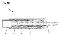
より具体的には、図1Aは、ねじ付きの主ねじ2、ねじ付きの近位部分4を有する外側管3、遠位の自由端6および近位のねじ付き部分7を有する内側駆動管5、および外側にねじが付けられた伝達管8を備える伸縮式駆動アセンブリ1を示す。動作状態では、アセンブリは、フレーム(図示せず)に取り付けられる。主ねじは、軸方向ならびに回転するz軸を画定する。 More specifically, FIG. 1A shows a threaded
主ねじ2は、いくつかの手段によりz軸に関してその近位端で回転駆動され、かつ3つの構成要素と相互作用する、すなわち、フレーム(図示せず)とのz軸平行移動ロック、外側管の近位のねじ付き部分4とのねじインターフェース、および伝達管8との摺動回転ロックインターフェースである。主ねじが回転すると、フレームに対して摺動回転ロックインターフェースを有する外側管は、主ねじのピッチおよび回転速度で決められる速度でz軸に沿って平行移動する。伝達管8は、3つのインターフェースを有する、すなわち、主ねじとの摺動回転ロックインターフェース、外側管とのz軸平行移動ロック9、および駆動管の近位のねじ付き部分7とのねじインターフェースである。主ねじが回転すると、摺動回転ロックは、伝達管に、同じ速度で回転するように強制する。伝達管が回転すると、外側管に対して摺動回転ロックインターフェースを有する内側駆動管は、外側管の平行移動速度に加えて、ピッチおよび回転速度により決められる速度でz軸に沿って平行移動する。示されているように、主ねじが回転したとき、外側管は、遠位方向に移動し、また内側管は、外側管の外へと遠位方向に「伸縮される」、これは図1Bで示されている。 The
伸縮式駆動アセンブリの適正な機能のために、すべてのインターフェースは、内側管が前方に駆動されると、比較的長い距離に沿って自由に平行移動し、かつ/または回転し続ける必要があり、そのためには、構成要素が可動性を確実に維持するように、構成要素に対する小さな許容差が必要になり得る。さらに、構成要素間の隙間を最小化することにより、伸縮式駆動アセンブリの寸法を可能な限り小さく保つことが望ましい可能性がある。これは、さらに小さな構成要素の許容差が必要になり得る。これらの問題に対処するために、本発明の実施形態は、構成要素間でさらなる自由度を可能にする特別な運動学的継手を提供する。 For proper functioning of the telescoping drive assembly, all interfaces must be free to translate and / or continue to rotate along a relatively long distance when the inner tube is driven forward, This may require a small tolerance for the component to ensure that the component remains mobile. Furthermore, it may be desirable to keep the dimensions of the telescopic drive assembly as small as possible by minimizing the gap between the components. This may require even smaller component tolerances. To address these issues, embodiments of the present invention provide special kinematic joints that allow additional degrees of freedom between components.
本発明の例示的な実施形態を参照すると、図2Aは、ねじ付きの主ねじ120、外側管アセンブリ、内側駆動管150、および伝達管180を備える伸縮式駆動アセンブリ100を開示する。構成要素は、基本的に上記で述べた従来設計のものと同じ機能的関係を有するが、外側管部材を置き換える外側管アセンブリは、示された実施形態で、概してリング形状のオルダム継手部材160を介してベース部材140に結合されるガイド管130、ならびにベース部材に収容されるナット部材170の形態の4つの部材を備える。図2Bは、図1Bで示された状態に対応する部分的に伸縮された状態にある伸縮式駆動アセンブリ100を示す。 Referring to an exemplary embodiment of the present invention, FIG. 2A discloses a
図2A、図3、および図4を参照すると以下では、伸縮式駆動アセンブリ100の個々の構成要素のより詳細な記述が与えられる。より具体的には、主ねじ120は、外側のねじ山121と、入力シャフトとして働き、かつ例えば、歯車などの駆動部材を取り付けることのできる1対の対向する平坦な面を有する近位端122と、フレーム部材の対応する座に係合するように適合された部分的に球形な表面部分123とを備える。ねじ山の長さに沿って、伝達管180上の対向する内側面に係合し、それにより、その間に摺動回転ロックインターフェースを提供するように適合された2つの対向する共面の摺動面124が提供される。 With reference to FIGS. 2A, 3, and 4, a more detailed description of the individual components of the
ナット部材170は、ベース部材の対応する座142に係合するように適合された部分的に球形な表面部分172と、ベース部材の対応するヒンジ座143に係合するように適合された1対の対向する半径方向に突き出た丸いヒンジピン173と、主ねじの外ねじ121に係合するように適合された内側ねじとを備え、z軸に回転ロックを提供するピンは、なお、ナット部材が、ピンにより画定されるヒンジ軸に対応して枢動できるようにする(通常、数度の回転)。代替的に、ナット部材がベース部材で「カルダン的に」動くことを可能にするようにさらなるヒンジを提供することもできる。 The
ベース部材140は、オルダム継手部材上の、1対の近位方向に突き出たフック部分164上の対応する面に係合し、それによりそれらの間に1対の摺動回転ロックインターフェースを提供するように適合された1対の対向する共面の摺動面144と、伝達管上の近位のフランジ部分185を把持し、かつ係合し、それによりz軸平行移動ロックを提供するように適合された1対の対向する遠位方向に突き出たフック部分145と、フレーム部材に形成された対応するガイドスロットに係合し、それによりそれらの間にスプライン摺動回転ロックインターフェースを提供するように適合された1対の軸方向に延びる対向するガイド突起部146とをさらに備える。ガイド突起部の外側面は、含まれる構成要素が正確に位置合せされる必要性を低減するために、軸方向および/または円周方向に湾曲させることができる。対向するフック部分145は、対向する摺動面144に対して、90度オフセットされる。
オルダム継手部材160は、継手部材をベース部材に軸方向にロックするように適合された、内側を向いたフック縁部を備える上記で述べたフック部分164と、フック部分164に対して90度オフセットして配置され、かつガイド管上の1対の近位方向に突き出たフック部分136上の対応する面に係合して、それらの間で摺動回転ロックインターフェースを提供するように適合された1対の対向する横断的な外側隆起構造166とを備える。回転ロックをさらに提供するために、オルダム継手部材は、ベース部材フック部分145を受け入れるように適合された1対の対向する切欠き165と、フック部分164の1対の対向する遠位方向を向いた延長部167とを備え、その延長部は、ガイド管の1対の対応する切欠き137に受け入れられるように適合される。
ガイド管130は、上記で述べたフック部分136および切欠き165,ならびに内側駆動管150上に形成された対応する近位のガイド突起部152に係合し、それによりそれらの間にスプライン摺動回転ロックインターフェースを提供するように適合された1対の軸方向に延びる対向するガイド溝132を備える。ガイド突起部の外側面は、含まれる構成要素が正確に位置合せされる必要性を低減するために、軸方向および/または円周方向に湾曲させることができる。
伝達管180は、内側駆動管上の対応する近位の内ねじ151(図2Aを参照のこと)に係合するように適合された外ねじ181と、主ねじ摺動面に係合する上記で述べた内側面を提供する1対の対向する共面の壁部分184と、ベース部材フック部分145により軸方向にロックされて保持される上記で述べた近位のフランジ部分185と、主ねじを支持するように適合された1対の対向する内側軸方向に方向付けられた突起部186(図2Aを参照のこと)とを備える。 The
内側駆動管150は、上記で述べた内ねじ151、およびガイド突起部152、ならびに伝達管を支持するように適合された1対の対向する内側軸方向を向いた突起部156を備える。 The
示されるように、述べられた伸縮式駆動アセンブリ100は、アセンブリの伝達効率を妨げることなく、駆動アセンブリの高められた柔軟性をそれぞれが提供する2つの別個の機構を備える。より具体的には、ベース部材140またはガイド管130とのオルダム継手部材160の組み合わされたインターフェースは、ガイド管が、ベース部材の回転するz軸に直角な平面内で動くことができるように提供するが、ベース部材とガイド管の間の回転ロックも提供する。したがって、ナット部材とベース部材の間で形成されるヒンジは、ナット部材と、したがって主ねじとが、ヒンジ軸に対応して枢動できるようにするが、ナット部材とベース部材の間の回転ロックも提供する。2つの機構は、別個のものであり、かつ独立しているので、第1の代替的な実施形態では、ベース部材およびガイド部材は、単一の要素として形成され得るが、同様に第2の代替の実施形態では、ベース部材、オルダム継手部材、およびガイド管は、単一の要素として形成することができる。 As shown, the described
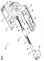
図5および図6を参照すると、モータ駆動の「箱型の」薬剤送達装置200が述べられ、装置は、円筒形の本体部分と、遠位の針が貫通可能な隔壁を有する遠位の出口部分と、近位の開放端部分と、吐出機構(以下を参照のこと)の一部を形成するピストン駆動体がピストンに係合できるようにする近位面を有する軸方向に変位可能なピストンとを備える薬物カートリッジを受け入れるように適合される。カートリッジは、例えば、インスリン、GLP−1、または成長ホルモン製剤の形態の薬剤を含むことができる。カートリッジは、針ハブ取付台の形態の遠位の結合手段を備えることができる。 Referring to FIGS. 5 and 6, a motor-driven “box-shaped”
より具体的には、ペン装置は、キャップ部分201と、上側ハウジング部材220および下側ハウジング部材230により形成される主部分202とを備え、ハウジング部材は、薬剤吐出機構および関連するコントローラ電子装置233が配置される近位の駆動アセンブリ部分と、再充電可能なエネルギー源231(電池)が配置される遠位部分とを有する内部を形成する。遠位部分は、遠位の開口部242を介して薬剤で充填された透明なカートリッジを受け入れるように適合された前面装填式のカートリッジホルダコンパートメント232をさらに備え、受け入れられたカートリッジは、ハウジング部材に取り付けられたカートリッジホルダロッキングアセンブリ240により定位置に保持される。ばねで作動される、軸方向に移動可能なカートリッジ付勢部材(図示せず)は、カートリッジホルダコンパートメント内で近位に配置される。対応するカートリッジ付勢部材は、EP出願第14159913.4号で述べられている。 More specifically, the pen device comprises a
上側ハウジング部材は、ユーザがそれを通してディスプレイ(図示せず)を観察できる窓部221と、ユーザ入力キーとを備える。示された実施形態では、1対の用量設定入力キー225、226は、ディスプレイに示された薬剤の望ましい用量を手動で設定するように働き、次いで、遠位に配置された放出ボタン227が作動したとき、その用量を吐出することができる。側面開口部228は、例えば、USBなどの電気的なコネクタを挿入可能にし、コネクタは電池に充電を提供し、ならびに例えば、PCなどの外部装置との間でデータ送信を可能にする。さらにコントローラ電子装置は、受信器および/または送信器と関連付ける、または備えることができ、装置が、例えば、Bluetooth,NFC、またはWi−Fiなどの無線手段により外部ソースと通信できるようにする。このように、吐出された用量の記録を、PCまたはスマートフォンに転送することもでき、あるいはスマートフォンを、事前設定された用量サイズを簡便に入力するために使用することもできる。 The upper housing member includes a
薬剤吐出機構は、フレーム部材250と、モータおよび歯車アセンブリ260と、上記で述べた伸縮式駆動アセンブリ100とを備え、内側駆動管150は、装填されたカートリッジのピストンの近位の自由面と係合するように適合された遠位部分151を備える。本発明の一部を形成するものではないが、駆動管遠位部分は、例えば、WO2013/144152で開示されるように、近接検出を用いるなど、駆動管とピストンの間の接触を検出するための電子的なセンサ手段を備えることができる。代替的に、例えば、電流を監視することによるなど、モータに対する負荷を監視することにより、接触を検出することもできる。フレーム部材250は、ベースプレート部分251と、モータおよび歯車アセンブリを受け入れるように適合された短い第1の管状の支持体252と、伸縮式駆動アセンブリを受け入れるように適合された、より長い同軸に配置された第2の管状の支持体253とを備える。モータおよび歯車アセンブリの回転する出力シャフト261は、取り付けられたとき、ベースプレート部分の第1の開口部を通って突き出し、かつ伸縮式駆動アセンブリの入力シャフトは、ベースプレートの第2の開口部を通して突き出し、2つのシャフトは、出力または入力シャフト上に取り付けられた1対の伝達歯車265、266により回転するように結合される。第2の管状の支持体は、ベース部材のガイド突起部146と係合し、それによりフレームとベース部材の間で、またガイド管との間で摺動回転ロックインターフェースを提供するように適合された1対の対向するガイド溝256を備える。 The drug delivery mechanism includes a
カートリッジホルダロッキングアセンブリ240は、受入れ開口部242と、1対の対向する可撓性のあるカートリッジホルダアーム244とを有するハウジング241を備え、各アームは、把持肩部245を備える。作動部材として働くハウジングは、装置の主部分上に取り付けられ、受入れ開口部の中心を通る軸に対応して、例えば、90度回転するように適合され、作動部材の前後回転は、把持肩部の、閉じた位置または開口位置への出入の動きを制御する。示された実施形態では、把持肩部245は、Novo Nordisk A/S社、デンマークにより製作され、かつ販売されるPenfill(登録商標)で提供され、米国特許第5,693,027号で述べられるように、円周方向に離間された複数の把持歯部を備えて、カートリッジハブ取付台を把持するように意図された複数の間隙を提供する。作動部材は、主ハウジングと同一面になるように回転され、カートリッジホルダアームがその動作する閉じた保持位置に後退される動作位置と、作動部材が主ハウジングと非同一面となるように回転され、カートリッジホルダアームが開放された装填位置へと延ばされ、カートリッジを取り外し、新しいものと交換できるようにする装填/非装填位置とを有する。示された実施形態では、作動部材に対するカートリッジホルダアームの動きは、対応するアームガイドトラック246に受け入れられるハウジングガイド突起部により制御される。把持肩部は、部分的に挿入されたカートリッジを把持し、カートリッジを、付勢手段の力に抗して完全に挿入される位置へと近位方向に移動させるように適合され得る。上記で述べたタイプの前面装填式のカートリッジホルダアセンブリは、WO2013/124119で開示される。 The cartridge
新しいカートリッジが挿入されたとき、駆動吐出手段は、近位に位置するピストンを有する新しいカートリッジが挿入可能である状態にある必要がある、すなわち、駆動管150は、後退されている必要がある。これは、モータで駆動管を後退させるために、ユーザが入力キーを動作させることにより手動で、またはロッキングアセンブリもしくは挿入されたカートリッジにより動作されるスイッチ手段により自動的に行うことができる。例えば、スイッチは、付勢部材により動作されるように構成することができ、スイッチは、付勢部材が、初期の非装填の遠位位置にある場合の初期の第1の状態と、付勢部材が作動位置へと近位方向に移動した場合の作動された第2の状態とを有する。付勢部材は、挿入されたカートリッジの近位部分に係合し、それにより、遠位方向への付勢力を加えるように適合され、かつカートリッジホルダロッキングアセンブリが、閉じた状態から開放状態へと作動された場合、受入れ開口部を通して少なくとも部分的に装填されたカートリッジを移動するように適合される。このような機構では、カートリッジが装填され、定位置にロックされたので、スイッチ手段が、第1の状態から第2の状態に作動されたとき、後退した駆動管150は、遠位方向に移動して、装填されたカートリッジのピストンに係合し、また駆動管は、スイッチ手段が第2の状態から第1の状態へと作動されたとき後退され、装填されたカートリッジが開放され、遠位方向に移動する。対応するスイッチ機構は、EP出願第14159913.4号に述べられている。 When a new cartridge is inserted, the drive ejection means needs to be ready for insertion of a new cartridge with a proximally located piston, i.e.
ユーザがカートリッジ(完全にまたは部分的に空であり得る)を取り外したいと望むとき、ユーザは、作動部材をその装填/非装填位置へと回転し、それにより、カートリッジホルダの把持肩部は、その開放位置へと移動され、これは、付勢部材の遠位方向に向けられた付勢力によりカートリッジを近位方向に押すことができる。カートリッジがカートリッジホルダから「飛び出す」、または摺動して外れるのを阻止するために、わずかな摩擦が、カートリッジホルダと装填されたカートリッジの間で提供され得る。付勢部材は、ばねにより遠位方向に移動されるので、付勢部材は、カートリッジスイッチの係合を解除する。閉じた状態から開放状態へのカートリッジスイッチの作動は、2つのアクションが行われたと想定され得ることを装置コントローラに知らせる、すなわち(i)カートリッジホルダが開いていること、および(ii)挿入されたカートリッジが、付勢部材により遠位方向に押されており、これは、駆動管の、図2Aに対応するその完全に後退した位置へと後退を開始することである。ピストン管を後退させるには、何らかの時間がかかるので、ユーザは、ピストン管が完全に後退される前に、通常、カートリッジを取り外すことになるが、すべての位置におけるピストン管は、カートリッジホルダの完全に内側に位置するので、意図されない損傷に対して保護される。通常の使用状況中ではピストン管は、ユーザが新しいカートリッジを挿入するとき、完全に後退されるものと想定されるが、新しいカートリッジの挿入が、「速すぎる」のを阻止するために、ユーザは、例えば、音声信号などで、装置がカートリッジを受け入れる用意ができたことを示す信号を待つように指示され得る。 When the user wishes to remove the cartridge (which may be completely or partially empty), the user rotates the actuating member to its loading / unloading position so that the gripping shoulder of the cartridge holder Moved to its open position, which can push the cartridge proximally by a biasing force directed distally of the biasing member. A slight friction can be provided between the cartridge holder and the loaded cartridge to prevent the cartridge from “jumping” out of the cartridge holder or sliding off. Since the biasing member is moved in the distal direction by the spring, the biasing member releases the engagement of the cartridge switch. Actuation of the cartridge switch from the closed state to the open state informs the device controller that two actions can be assumed to have taken place: (i) the cartridge holder is open, and (ii) inserted The cartridge is pushed distally by the biasing member, which is to begin to retract the drive tube to its fully retracted position corresponding to FIG. 2A. Since it takes some time to retract the piston tube, the user will usually remove the cartridge before the piston tube is fully retracted, but the piston tube in all positions Because it is located inside, it is protected against unintended damage. During normal use, the piston tube is assumed to be fully retracted when the user inserts a new cartridge, but in order to prevent the insertion of a new cartridge from being "too fast" For example, an audio signal may be instructed to wait for a signal indicating that the device is ready to accept the cartridge.
例示的な実施形態の上記の説明では、様々な構成要素に対して前述の機能を提供する様々な構造および手段が、当業者である読者に本発明の概念が明らかになる程度に述べられてきた。様々な構成要素に対する詳細な構成および仕様は、本明細書で提示された方針に沿って当業者により実施される通常の設計手順の対象であると考えられる。 In the above description of exemplary embodiments, various structures and means for providing the aforementioned functionality for various components have been set forth to the extent that the concept of the invention will be apparent to those skilled in the art. It was. Detailed configurations and specifications for the various components are considered to be the subject of normal design procedures performed by those skilled in the art in accordance with the policies presented herein.
Claims (9)
Translated fromJapanese外ねじ(121)を備え、かつ回転軸を画定する細長い駆動部材(120)であり、前記フレームに対して軸方向にロックされるが、自由に回転するように構成された駆動部材(120)と、
前記駆動部材に対して軸方向に移動可能であるが、前記フレームに対して回転しないように構成される外側管アセンブリであり、前記駆動部材の外ねじとねじ係合されるナット部材(170)を備える外側管アセンブリと、
外ねじ(181)を備える伝達管(180)であり、
前記駆動部材と同軸に、かつ前記外側管アセンブリの内側に配置され、
前記駆動部材に対して軸方向に移動可能であるが、回転しないように構成され、かつ
前記外側管アセンブリに対して軸方向にロックされるが、自由に回転するように構成される、伝達管(180)と、
前記伝達管の外ねじとねじ係合される駆動管(150)であり、
前記駆動部材と同軸に配置され、かつ
前記外側管アセンブリに対して軸方向に移動可能であるが、回転しないように構成される、駆動管(150)とを備え、
前記外側管アセンブリが、前記回転軸に対応して、前記ナット部材に対して回転しないように結合される外側管部分(130、140、160)を備え、前記外側管部分は、前記回転軸に直角な少なくとも1つの軸に対応して、前記ナット部材に対して枢動することができる、駆動アセンブリ(100)。A frame (250);
An elongate drive member (120) comprising an outer screw (121) and defining a rotational axis, the drive member (120) being axially locked to the frame but configured to rotate freely When,
A nut member (170) that is axially movable relative to the drive member, but is an outer tube assembly configured to not rotate relative to the frame and is threadedly engaged with an external thread of the drive member An outer tube assembly comprising:
A transmission tube (180) comprising an external screw (181);
Disposed coaxially with the drive member and inside the outer tube assembly;
A transmission tube that is axially movable with respect to the drive member but is configured not to rotate and is axially locked with respect to the outer tube assembly but configured to rotate freely. (180),
A drive tube (150) threadedly engaged with an external thread of the transmission tube;
A drive tube (150) disposed coaxially with the drive member and axially movable relative to the outer tube assembly, but configured to not rotate;
The outer tube assembly includes an outer tube portion (130, 140, 160) that is coupled to the nut member so as not to rotate with respect to the rotation shaft, and the outer tube portion is connected to the rotation shaft. A drive assembly (100) capable of pivoting relative to the nut member corresponding to at least one axis at right angles.
前記ベース部材は、前記ナット部材に結合され、かつ
前記ベース部材および前記管ガイド部材は、オルダム継手(160)を介して互いに結合される、請求項1に記載の駆動アセンブリ。The outer tube portion is in the form of an assembly comprising a base member (140) and a tube guide member (130);
The drive assembly of claim 1, wherein the base member is coupled to the nut member, and the base member and the tube guide member are coupled to each other via an Oldham coupling (160).
前記ガイド突起部は、それぞれ、前記軸方向に外側に向けて湾曲した外側係合面を備える、請求項4に記載の駆動アセンブリ。The drive tube (150) includes a number of outer guide protrusions (152), and the tube guide member (130) includes a number of inner guide grooves (132) configured to receive the guide protrusions. And each of the guide protrusions includes an outer engagement surface that is curved outward in the axial direction.
前記細長い駆動部材を回転させるように適合された電子的に制御される駆動手段(260)とをさらに備え、
前記駆動管が、装填されたカートリッジの前記ピストンに直接または間接的に係合し、かつ軸方向に移動させて、それにより前記カートリッジから薬剤を吐出するように適合されている、請求項1から6のいずれか一項に記載の駆動アセンブリ(100)を備える、薬剤送達装置(200)。A compartment (232) adapted to receive a cartridge filled with a medicament, wherein the cartridge is adapted to be configured in fluid communication with a body portion, an axially displaceable piston, and a flow conduit. A compartment (232) comprising a distal outlet portion,
Electronically controlled drive means (260) adapted to rotate the elongate drive member;
2. The drive tube is adapted to engage directly or indirectly with the piston of a loaded cartridge and move axially thereby ejecting a drug from the cartridge. A drug delivery device (200) comprising the drive assembly (100) of any one of claims 6.
Applications Claiming Priority (3)
| Application Number | Priority Date | Filing Date | Title |
|---|---|---|---|
| EP14000379.9 | 2014-02-03 | ||
| EP14000379 | 2014-02-03 | ||
| PCT/EP2015/052149WO2015114158A1 (en) | 2014-02-03 | 2015-02-03 | Telescopic drive arrangement |
Publications (1)
| Publication Number | Publication Date |
|---|---|
| JP2017510391Atrue JP2017510391A (en) | 2017-04-13 |
Family
ID=50068774
Family Applications (1)
| Application Number | Title | Priority Date | Filing Date |
|---|---|---|---|
| JP2016567160AWithdrawnJP2017510391A (en) | 2014-02-03 | 2015-02-03 | Telescopic drive mechanism |
Country Status (5)
| Country | Link |
|---|---|
| US (1) | US20170007774A1 (en) |
| EP (1) | EP3102260A1 (en) |
| JP (1) | JP2017510391A (en) |
| CN (1) | CN105979989A (en) |
| WO (1) | WO2015114158A1 (en) |
Cited By (1)
| Publication number | Priority date | Publication date | Assignee | Title |
|---|---|---|---|---|
| WO2024004330A1 (en)* | 2022-06-28 | 2024-01-04 | テルモ株式会社 | Medicinal solution administration device |
Families Citing this family (26)
| Publication number | Priority date | Publication date | Assignee | Title |
|---|---|---|---|---|
| US9656019B2 (en) | 2007-10-02 | 2017-05-23 | Medimop Medical Projects Ltd. | Apparatuses for securing components of a drug delivery system during transport and methods of using same |
| US10420880B2 (en) | 2007-10-02 | 2019-09-24 | West Pharma. Services IL, Ltd. | Key for securing components of a drug delivery system during assembly and/or transport and methods of using same |
| BRPI0817907B8 (en) | 2007-10-02 | 2021-06-22 | Lamodel Ltd | apparatus for administering a substance to an individual |
| WO2015165992A1 (en) | 2014-05-02 | 2015-11-05 | Novo Nordisk A/S | Telescopic drive arrangement for drug delivery device |
| US10149943B2 (en) | 2015-05-29 | 2018-12-11 | West Pharma. Services IL, Ltd. | Linear rotation stabilizer for a telescoping syringe stopper driverdriving assembly |
| CN113181477B (en)* | 2015-06-04 | 2023-07-14 | 麦迪麦珀医疗工程有限公司 | Cartridge insertion for drug delivery device |
| US10086145B2 (en) | 2015-09-22 | 2018-10-02 | West Pharma Services Il, Ltd. | Rotation resistant friction adapter for plunger driver of drug delivery device |
| US9987432B2 (en) | 2015-09-22 | 2018-06-05 | West Pharma. Services IL, Ltd. | Rotation resistant friction adapter for plunger driver of drug delivery device |
| US10576207B2 (en) | 2015-10-09 | 2020-03-03 | West Pharma. Services IL, Ltd. | Angled syringe patch injector |
| US11318254B2 (en) | 2015-10-09 | 2022-05-03 | West Pharma. Services IL, Ltd. | Injector needle cap remover |
| EP3711793B1 (en) | 2016-01-21 | 2021-12-01 | West Pharma Services IL, Ltd. | A method of connecting a cartridge to an automatic injector |
| US10646643B2 (en) | 2016-01-21 | 2020-05-12 | West Pharma. Services IL, Ltd. | Needle insertion and retraction mechanism |
| JP6885960B2 (en) | 2016-01-21 | 2021-06-16 | ウェスト ファーマ サービシーズ イスラエル リミテッド | Drug delivery device with visual indicators |
| US11389597B2 (en) | 2016-03-16 | 2022-07-19 | West Pharma. Services IL, Ltd. | Staged telescopic screw assembly having different visual indicators |
| US10376647B2 (en)* | 2016-03-18 | 2019-08-13 | West Pharma. Services IL, Ltd. | Anti-rotation mechanism for telescopic screw assembly |
| US11338090B2 (en) | 2016-08-01 | 2022-05-24 | West Pharma. Services IL, Ltd. | Anti-rotation cartridge pin |
| JP7059251B2 (en) | 2016-08-01 | 2022-04-25 | ウェスト ファーマ サービシーズ イスラエル リミテッド | A spring that prevents the door from closing halfway |
| EP3630226A1 (en) | 2017-05-30 | 2020-04-08 | West Pharma. Services Il, Ltd. | Modular drive train for wearable injector |
| US11583634B2 (en) | 2017-11-03 | 2023-02-21 | Sanofi | Plunger and drug delivery device |
| JP7402799B2 (en) | 2017-12-22 | 2023-12-21 | ウェスト ファーマ サービシーズ イスラエル リミテッド | Syringes available with different cartridge sizes |
| CN109443828A (en)* | 2018-10-29 | 2019-03-08 | 迈卓泰科(天津)医疗科技有限公司 | A kind of threaded connection sampler barrel |
| GB2584730B (en)* | 2019-06-14 | 2022-04-13 | Owen Mumford Ltd | Drug delivery device assembly |
| CN110440178A (en)* | 2019-07-16 | 2019-11-12 | 闫志伟 | A kind of intelligent integrated lamps and lanterns based on city management security protection |
| CN111098297B (en)* | 2020-01-21 | 2024-01-16 | 深圳瀚维智能医疗科技有限公司 | Telescoping mechanism of manipulator and manipulator |
| CN115704475A (en)* | 2021-08-16 | 2023-02-17 | 江苏鲁汶仪器股份有限公司 | Magnetic fluid sealing shaft |
| DE102023134801A1 (en)* | 2023-12-12 | 2025-06-12 | Deutsches Zentrum für Luft- und Raumfahrt e.V. | Heliostat |
Family Cites Families (8)
| Publication number | Priority date | Publication date | Assignee | Title |
|---|---|---|---|---|
| DE804455C (en)* | 1949-10-14 | 1951-04-23 | Hauptner Instrumentenfabrik H | Precision injection syringe |
| WO1997000091A1 (en)* | 1995-06-14 | 1997-01-03 | Berney Jean Claude | Linear-transmission syringe plunger |
| JP3664406B1 (en)* | 2004-09-16 | 2005-06-29 | サイエンティフィックテクノロジーズ有限会社 | Power transmission method and apparatus having load-sensitive thrust amplification mechanism |
| US7887521B2 (en)* | 2006-05-17 | 2011-02-15 | Alcon Research, Ltd. | Ophthalmic injection system |
| BRPI0817907B8 (en)* | 2007-10-02 | 2021-06-22 | Lamodel Ltd | apparatus for administering a substance to an individual |
| US9345836B2 (en)* | 2007-10-02 | 2016-05-24 | Medimop Medical Projects Ltd. | Disengagement resistant telescoping assembly and unidirectional method of assembly for such |
| WO2010076792A1 (en)* | 2008-12-31 | 2010-07-08 | Medingo Ltd. | Portable medical fluid delivery device with drive screw articulated with reservoir plunger |
| EP2332600A1 (en)* | 2009-12-09 | 2011-06-15 | F. Hoffmann-La Roche AG | A method of filling a container with a liquid drug |
- 2015
- 2015-02-03JPJP2016567160Apatent/JP2017510391A/ennot_activeWithdrawn
- 2015-02-03USUS15/115,781patent/US20170007774A1/ennot_activeAbandoned
- 2015-02-03CNCN201580007057.7Apatent/CN105979989A/ennot_activeWithdrawn
- 2015-02-03EPEP15705221.8Apatent/EP3102260A1/ennot_activeWithdrawn
- 2015-02-03WOPCT/EP2015/052149patent/WO2015114158A1/enactiveApplication Filing
Cited By (1)
| Publication number | Priority date | Publication date | Assignee | Title |
|---|---|---|---|---|
| WO2024004330A1 (en)* | 2022-06-28 | 2024-01-04 | テルモ株式会社 | Medicinal solution administration device |
Also Published As
| Publication number | Publication date |
|---|---|
| CN105979989A (en) | 2016-09-28 |
| WO2015114158A1 (en) | 2015-08-06 |
| EP3102260A1 (en) | 2016-12-14 |
| US20170007774A1 (en) | 2017-01-12 |
Similar Documents
| Publication | Publication Date | Title |
|---|---|---|
| JP2017510391A (en) | Telescopic drive mechanism | |
| JP2017513537A (en) | Telescopic drive mechanism with Oldham coupling | |
| JP6228935B2 (en) | Drug delivery device having a front insertion structure | |
| JP6681388B2 (en) | Drug delivery device with cartridge alignment features | |
| JP6637062B2 (en) | Drug delivery device with dose reset mechanism | |
| JP6644793B2 (en) | Spring driven drug delivery device | |
| JP2016522038A (en) | Drug delivery device having means for disabling the release mechanism | |
| US10137254B2 (en) | Telescopic drive arrangement for drug delivery device | |
| JP2017502809A (en) | Transmission mechanism for a motor-driven drug delivery device | |
| JP2016537058A (en) | Drug delivery device with front loading function | |
| CN105705181A (en) | Medicament delivery device | |
| CN108136130B (en) | Method of making a prefilled drug delivery device | |
| JP2017527405A (en) | Drug delivery device with piston driver distal feature | |
| JP2025010244A (en) | AUTOINJECTION DEVICE WITH RECONFIGURATION CAPABILITY FOR MULTIPLE CHAMBER DRUG CARTRIDGES - Patent application | |
| JP6893507B2 (en) | Drug delivery device with a slender drive mechanism | |
| JP6932644B2 (en) | Drug delivery device with a spring mechanism | |
| US20160271335A1 (en) | Drive Mechanism for an Injection Device |
Legal Events
| Date | Code | Title | Description |
|---|---|---|---|
| A621 | Written request for application examination | Free format text:JAPANESE INTERMEDIATE CODE: A621 Effective date:20180131 | |
| A761 | Written withdrawal of application | Free format text:JAPANESE INTERMEDIATE CODE: A761 Effective date:20190107 |