JP2017506961A - System for introducing pulsation in fluid output for oral care devices - Google Patents
System for introducing pulsation in fluid output for oral care devicesDownload PDFInfo
- Publication number
- JP2017506961A JP2017506961AJP2016554843AJP2016554843AJP2017506961AJP 2017506961 AJP2017506961 AJP 2017506961AJP 2016554843 AJP2016554843 AJP 2016554843AJP 2016554843 AJP2016554843 AJP 2016554843AJP 2017506961 AJP2017506961 AJP 2017506961A
- Authority
- JP
- Japan
- Prior art keywords
- flow
- assembly
- fluid
- nozzle
- instrument
- Prior art date
- Legal status (The legal status is an assumption and is not a legal conclusion. Google has not performed a legal analysis and makes no representation as to the accuracy of the status listed.)
- Granted
Links
Images


Classifications
- A—HUMAN NECESSITIES
- A61—MEDICAL OR VETERINARY SCIENCE; HYGIENE
- A61C—DENTISTRY; APPARATUS OR METHODS FOR ORAL OR DENTAL HYGIENE
- A61C1/00—Dental machines for boring or cutting ; General features of dental machines or apparatus, e.g. hand-piece design
- A61C1/02—Dental machines for boring or cutting ; General features of dental machines or apparatus, e.g. hand-piece design characterised by the drive of the dental tools
- A—HUMAN NECESSITIES
- A61—MEDICAL OR VETERINARY SCIENCE; HYGIENE
- A61C—DENTISTRY; APPARATUS OR METHODS FOR ORAL OR DENTAL HYGIENE
- A61C17/00—Devices for cleaning, polishing, rinsing or drying teeth, teeth cavities or prostheses; Saliva removers; Dental appliances for receiving spittle
- A61C17/02—Rinsing or air-blowing devices, e.g. using fluid jets or comprising liquid medication
- A—HUMAN NECESSITIES
- A61—MEDICAL OR VETERINARY SCIENCE; HYGIENE
- A61C—DENTISTRY; APPARATUS OR METHODS FOR ORAL OR DENTAL HYGIENE
- A61C1/00—Dental machines for boring or cutting ; General features of dental machines or apparatus, e.g. hand-piece design
- A61C1/0061—Air and water supply systems; Valves specially adapted therefor
- A—HUMAN NECESSITIES
- A61—MEDICAL OR VETERINARY SCIENCE; HYGIENE
- A61C—DENTISTRY; APPARATUS OR METHODS FOR ORAL OR DENTAL HYGIENE
- A61C17/00—Devices for cleaning, polishing, rinsing or drying teeth, teeth cavities or prostheses; Saliva removers; Dental appliances for receiving spittle
- A61C17/02—Rinsing or air-blowing devices, e.g. using fluid jets or comprising liquid medication
- A61C17/028—Rinsing or air-blowing devices, e.g. using fluid jets or comprising liquid medication with intermittent liquid flow
- B—PERFORMING OPERATIONS; TRANSPORTING
- B05—SPRAYING OR ATOMISING IN GENERAL; APPLYING FLUENT MATERIALS TO SURFACES, IN GENERAL
- B05B—SPRAYING APPARATUS; ATOMISING APPARATUS; NOZZLES
- B05B1/00—Nozzles, spray heads or other outlets, with or without auxiliary devices such as valves, heating means
- B05B1/02—Nozzles, spray heads or other outlets, with or without auxiliary devices such as valves, heating means designed to produce a jet, spray, or other discharge of particular shape or nature, e.g. in single drops, or having an outlet of particular shape
- B05B1/08—Nozzles, spray heads or other outlets, with or without auxiliary devices such as valves, heating means designed to produce a jet, spray, or other discharge of particular shape or nature, e.g. in single drops, or having an outlet of particular shape of pulsating nature, e.g. delivering liquid in successive separate quantities
- B05B1/083—Nozzles, spray heads or other outlets, with or without auxiliary devices such as valves, heating means designed to produce a jet, spray, or other discharge of particular shape or nature, e.g. in single drops, or having an outlet of particular shape of pulsating nature, e.g. delivering liquid in successive separate quantities the pulsating mechanism comprising movable parts
- B05B1/086—Nozzles, spray heads or other outlets, with or without auxiliary devices such as valves, heating means designed to produce a jet, spray, or other discharge of particular shape or nature, e.g. in single drops, or having an outlet of particular shape of pulsating nature, e.g. delivering liquid in successive separate quantities the pulsating mechanism comprising movable parts with a resiliently deformable element, e.g. sleeve
- G—PHYSICS
- G06—COMPUTING OR CALCULATING; COUNTING
- G06F—ELECTRIC DIGITAL DATA PROCESSING
- G06F30/00—Computer-aided design [CAD]
- G06F30/20—Design optimisation, verification or simulation
- G—PHYSICS
- G06—COMPUTING OR CALCULATING; COUNTING
- G06F—ELECTRIC DIGITAL DATA PROCESSING
- G06F30/00—Computer-aided design [CAD]
- G06F30/30—Circuit design
- G06F30/32—Circuit design at the digital level
- G06F30/327—Logic synthesis; Behaviour synthesis, e.g. mapping logic, HDL to netlist, high-level language to RTL or netlist
- G—PHYSICS
- G06—COMPUTING OR CALCULATING; COUNTING
- G06F—ELECTRIC DIGITAL DATA PROCESSING
- G06F30/00—Computer-aided design [CAD]
- G06F30/30—Circuit design
- G06F30/39—Circuit design at the physical level
- G06F30/392—Floor-planning or layout, e.g. partitioning or placement
- G—PHYSICS
- G06—COMPUTING OR CALCULATING; COUNTING
- G06F—ELECTRIC DIGITAL DATA PROCESSING
- G06F30/00—Computer-aided design [CAD]
- G06F30/30—Circuit design
- G06F30/39—Circuit design at the physical level
- G06F30/394—Routing
Landscapes
- Engineering & Computer Science (AREA)
- Health & Medical Sciences (AREA)
- Theoretical Computer Science (AREA)
- Physics & Mathematics (AREA)
- Computer Hardware Design (AREA)
- Public Health (AREA)
- Life Sciences & Earth Sciences (AREA)
- Veterinary Medicine (AREA)
- General Health & Medical Sciences (AREA)
- Animal Behavior & Ethology (AREA)
- Dentistry (AREA)
- Epidemiology (AREA)
- Evolutionary Computation (AREA)
- General Engineering & Computer Science (AREA)
- Geometry (AREA)
- General Physics & Mathematics (AREA)
- Oral & Maxillofacial Surgery (AREA)
- Water Supply & Treatment (AREA)
- Computer Networks & Wireless Communication (AREA)
- Architecture (AREA)
- Nozzles (AREA)
Abstract
Translated fromJapaneseDescription
Translated fromJapanese本発明は、一般に、歯間洗浄に使用される口腔ケア器具に関し、特に、その器具からの出力される流体ジェットを妨害することによって流体パルスを生成することに関係する。 The present invention relates generally to oral care devices used for interdental cleaning, and more particularly to generating fluid pulses by interfering with an output fluid jet from the device.
歯肉(歯ぐき)の健康及び歯周病の予防は、歯間領域からの歯垢除去に関係なく重要であるけれども、歯間歯石の除去は、歯肉の健康のメンテナンス、歯周病の予防及び齲歯の減少のために重要である。 Although gingival health and prevention of periodontal disease are important regardless of plaque removal from the interproximal area, removal of interdental calculus is important for maintaining gingival health, preventing periodontal disease and caries. Is important for the reduction of
従って、種々の試みが、歯間洗浄及び歯肉ケアをより効果的にすることに関連して行われてきた。そのような試みは、流体ジェット及び流体液滴の器具を含む。流体ジェットは、歯間領域内の侵入深さ、歯石除去の効率及び歯ぐき領域の治療に対して効果的な技術であると証明されてきた。スラグ(slug)として知られることもある一連の液体パルスを形成するウォータージェットの脈動が、より大きく且つ局在化された衝撃応力を用いて効果的であり、それは、連続的なパルス/スラグのハンマリング効果;洗浄されている表面にわたる個々のパルス/スラグのより大きな速度;水の量に対する衝撃が与えられる領域の改善された比;歯質(substrate)からバイオフィルムを剥離するプロセスを高める荷重サイクル;及び、エネルギー損失を最小にする傾向がある短期間の荷重;のためであると示されてきた。 Accordingly, various attempts have been made in connection with making interdental cleaning and gingival care more effective. Such attempts include fluid jet and fluid droplet instruments. Fluid jets have proven to be an effective technique for penetration depth in the interdental region, the efficiency of calculus removal and the treatment of the gum region. The pulsation of the water jet, forming a series of liquid pulses, sometimes known as slugs, is effective with larger and localized impact stress, which is a continuous pulse / slag Hammering effect; greater speed of individual pulses / slag across the surface being cleaned; improved ratio of impacted area to the amount of water; load that enhances the process of peeling the biofilm from the substrate Has been shown to be due to cycles; and short-term loads that tend to minimize energy loss.
種々の機械的アプローチが、ウォータージェットを効果的に妨害して液体スラグを生成するのに使用されてきた。これらは、溝、穴又はスプロケットを含有する回転ディスク、遠心ローター、圧電駆動装置、急速弁駆動及び爆発的な沸騰を含む。これらの技術のうちそれぞれが、ウォータージェットから一連の液体パルス/スラグを実際に生成するけれども、これらは、複雑さ、費用及び短い寿命という欠点を有する。 Various mechanical approaches have been used to effectively block water jets to produce liquid slag. These include rotating disks containing grooves, holes or sprockets, centrifugal rotors, piezoelectric drives, rapid valve drives and explosive boiling. Although each of these technologies actually produces a series of liquid pulses / slag from a water jet, they have the disadvantages of complexity, cost and short lifetime.
従って、種々の既知の機械的且つ類似の駆動システム/方法に付随したエネルギー損失及び短い寿命を回避する、継続的なジェットから液体脈動を生成するシステムが望ましい。 Accordingly, a system that generates liquid pulsations from a continuous jet that avoids the energy loss and short life associated with various known mechanical and similar drive systems / methods is desirable.
従って、歯間領域を洗浄する口腔ケア器具が、流体ジェット流を生成する器具;ノズルアセンブリであって、該ノズルアセンブリからの開口部に流体ジェット流を方向づけるノズルアセンブリ;及び、ノズルアセンブリ内で支持部材によって支持される液体流インタラプタアセンブリ;を含み、インタラプタアセンブリは、ノズルを通る流体流によって最初の位置からそらされて、その流れを一時的に妨害し、次に、流れが減少するに従い上記の最初の位置まで戻り、流体流内に周期性の撹乱を導入し、ノズルの出口開口部から一連の流体パルスを生成する。 Accordingly, an oral care device that cleans the interdental area is a device that generates a fluid jet stream; a nozzle assembly that directs the fluid jet stream to an opening from the nozzle assembly; and a support within the nozzle assembly A liquid flow interrupter assembly supported by the member, wherein the interrupter assembly is diverted from its initial position by the fluid flow through the nozzle to temporarily obstruct its flow and then as described above as the flow decreases. Returning to the initial position, introducing periodic disturbances in the fluid flow, generating a series of fluid pulses from the outlet opening of the nozzle.
本発明は、歯間の洗浄において有用な器具から送達される流体ジェット流を、典型的には流体ジェット出力の形で妨害して、機械的/電気的に駆動される脈動装置に対抗して乱流特徴の使用を介して液体パルス、バースト又はスラグと呼ばれる脈動出力を生成するシステムである。乱流は、典型的には、エネルギー損失のため回避されるけれども、乱流と非乱流との移行範囲で作動することによって、層流を有して分散させられる一過性の渦の離脱が発生する。より高い渦度によって、器具のノズルを出るに従い流体パルス/スラグが安定化される。 The present invention counteracts mechanical / electrically driven pulsation devices by interfering with fluid jet flow delivered from appliances useful in interdental cleaning, typically in the form of fluid jet output. A system that generates pulsatile output called liquid pulses, bursts or slugs through the use of turbulence features. Although turbulence is typically avoided due to energy loss, transient vortex shedding separated by laminar flow by operating in the turbulent and non-turbulent transition range Will occur. The higher vorticity stabilizes the fluid pulse / slag as it exits the instrument nozzle.
本発明の実施形態は、流体がノズルアセンブリを通って移動するに従い流体と接触する変形可能な要素を含む。作動中及び機能中、その要素が流れによってそらされるに従い、その断面は流れを撹乱させるように変わり、そらす力を減らす。そらす力が減るに従い、要素は、その最初の位置まで戻り、器具のノズルから周期性の脈動液体流をもたらす。 Embodiments of the present invention include a deformable element that contacts the fluid as it moves through the nozzle assembly. During operation and function, as the element is deflected by the flow, the cross-section changes to disturb the flow, reducing the diverting force. As the diverting force decreases, the element returns to its initial position, resulting in a periodic pulsating liquid flow from the instrument nozzle.
乱流は、レイノルズ数Re=(pu2)/(μu/L)(p=流体密度、u=平均流速、μ=粘性係数及びL=特性長)として既知の無次元数によって特徴づけることができる。10,000よりも大きいレイノルズ数の流体流は典型的には乱流であり、低いレイノルズ数の流れは典型的には層状のままである。液体流の妨害をもたらす本構成は、乱流と層流との境界層の変化次第である。層/乱流の移行はレイノルズ数によって同定されないけれども、移行は、物体のサイズが徐々に増えるか、若しくは、流体の粘性が減らされる場合に、又は、流体の密度が増える場合に発生する。Turbulence can be characterized by a dimensionless number known as Reynolds number Re = (pu2 ) / (μu / L) (p = fluid density, u = average flow velocity, μ = viscosity coefficient and L = characteristic length). it can. Reynolds number fluid flows greater than 10,000 are typically turbulent and low Reynolds number flows typically remain laminar. This configuration, which results in disturbance of the liquid flow, depends on the boundary layer change between turbulent and laminar flow. Although the laminar / turbulent transition is not identified by the Reynolds number, the transition occurs when the size of the object increases gradually, or when the fluid viscosity is decreased, or when the fluid density increases.
液体流インタラプタアセンブリの種々の実施形態が以下に示され且つ記載される。 Various embodiments of the liquid flow interrupter assembly are shown and described below.
本発明の一実施形態が、図1A及び1Bにおいて示されている。図1Aは、流体ジェットを使用する歯間洗浄器具のノズルアセンブリ10を示している。流体ジェット器具の一例が、特許文献1において示されている。他の流体ジェット器具も使用することができる。ノズルアセンブリの基部が11で示されており、さらに、出口開口部12を含む。示されている実施形態において、出口開口部は、直径が約1.2mmである。ノズルアセンブリは、プラスチック等の硬質材料から作製される。ノズル内で出口12の前に画定されるのはチャンバ14である。チャンバ14は後方部分16を含み、後方部分16を通って、器具からの流体の流れが方向づけられる。示されている実施形態において、チャンバの内面は、先端領域に向かって徐々に狭くなるように、ポイント17にて約15°内側に曲がって進む。この斜めの部分は約6mmの長さであり、さらに、18で参照される。流れ部材20は、チャンバ14内で支持されている。 One embodiment of the present invention is shown in FIGS. 1A and 1B. FIG. 1A shows a
示されている実施形態において、支持は、図1Bにおいて示されている可撓性の部材21である。示されている実施形態において、可撓性の部材21は、125マイクロメートルの厚さであり、さらに、流れ部材20とノズルの内面との間で延びる。可撓性の部材21は、作動中、カンチレバーのように作用する。示されている実施形態において、可撓性の部材21は、他の場所に置くこともできたけれども、内面が内側に曲がって進み始める17にて置かれている。示されている実施形態において、流れ部材は約2mmの長さであり、さらに、その前端にて先細りの部分24を有して概して円筒形であり、先細り部分は、ノズルチャンバの一致する先細り部分18と実質的に同じ角度を有する。流体圧力は、ノズルの入口にて約30psiである。 In the embodiment shown, the support is the
作動中、流れ部材がその最初の位置にある状態で、部材20の周りのノズルチャンバ内に器具からの液体が流れるに従い、液体は可撓性の支持部材21を押し、流れ部材20を、ノズルが閉まって流れを妨害するようになるまで出口に向かって動かす。ノズルを通る流れが減らされ、次に、止められるに従い、可撓性の支持部材に対する力は、流れ部材に対する支持部材の構成により解放されるため、流れ部材は、チャンバ内のその最初の位置まで戻り、復活した流体の流れをノズルの出口から出す。これによって、ノズルの出口12を出る妨害された脈動の流れ、すなわち脈動流が生成される。各パルス/スラグの周波数及び長さは、液体の流量、ノズルの出口と比較した流れ部材の断面積の比だけでなく、支持部材のばね定数及び流れ部材の質量によって決定される。チャンバの角度は、各パルスのいずれかの側での流速の増加/減少に影響を与え、パルスの形状をもたらす。 In operation, with the flow member in its initial position, as the liquid from the instrument flows into the nozzle chamber around the
図2A〜2Dは、脈動流体流を生成するための別の実施形態を4つの異形を用いて示している。いずれの場合にも、翼(ハイドロフォイル)が、ノズルチャンバ内でばねによって支持されている。示されている実施形態において、流れ部材は、翼の構成並びに支持ばねの構成及び配置に応じて、2つのタイプの並進運動及び2つのタイプの回転運動を有する。 2A-2D illustrate another embodiment for generating a pulsating fluid flow, with four variants. In either case, the wing (hydrofoil) is supported by a spring in the nozzle chamber. In the illustrated embodiment, the flow member has two types of translational movements and two types of rotational movements depending on the configuration of the wings and the configuration and arrangement of the support springs.
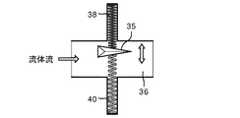
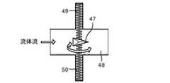
図2Aは、ノズルチャンバ30、並びに、ばね34及び36によってノズルチャンバ内で支持されるハイドロフォイルの翼32を例示している。図2Aは、1つの軸において他の軸よりも実質的に堅いばねによる、チャンバを通る液体流の方向における前後の翼の並進運動を示している。図2Bは、ノズルチャンバを通る液体流に対して90°であるばね38及び40の方向における経路に沿ったチャンバ36内での翼35の動きを示している。翼の構成は、翼を持ち上げ、次に、流れがまず減少し、次に妨害されるに従い解放するようなものである。図2Cは、ばね44及び46の方向に対して90°の軸を中心としたチャンバ43内での翼42の回転を示しており、図2Dは、ばね49及び50の軸を中心としたチャンバ48内での翼47の回転を示している。回転は、ページの面において非対称的な表面を有した翼を構成し、ページ内に及びページから回転させることによってもたらされる。 FIG. 2A illustrates a
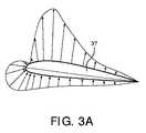
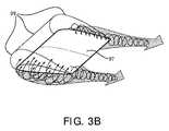
ハイドロフォイルの翼が位置を変えるに従い、翼の「尾部」のフラッターが脈動及び渦の離脱をもたらす。この効果は、翼37に関連して図3A及び3Bにおいて示されている。圧力プロファイルは39で参照されている。尾部が急に動くに従い渦が生じ、その渦は、最終的には離れることになる。離脱の間の流体に対する抗力の変化は、翼の後ろでの安定した渦の確立の間に、翼をその平衡位置まで戻す。 As the hydrofoil wing changes position, the wing “tail” flutter causes pulsations and vortex shedding. This effect is illustrated in FIGS. 3A and 3B in connection with
図2Bに関連して、液体が非対称的な翼を過ぎて流れるに従い、翼の前縁37のわずかな運動(持ち上げ)をもたらす。前縁がチャンバ内で位置を変えるに従い、流れはチャンバのその領域を介して減り、揚力を減らす。ハイドロフォイルの翼のサイズは、並進運動であろうが回転運動であろうが、チャンバ内でのその運動の結果として液体流を妨害するのに、もし完全には妨害しなければ、ほぼ妨害するのに十分でなければならない。場合によっては、翼に対するダメージを防ぐために、きわどい妨害が望ましくあり得る。 With reference to FIG. 2B, as the liquid flows past the asymmetric wing, it causes a slight movement (lifting) of the leading
図2A〜2Dのいずれの場合にも、プロセスが次に周期的に繰り返され得るように、ばねは、翼にその最初の位置まで戻るのを強制する傾向がある。渦の離脱と翼の振動との組み合わせは、ノズルの出口からの流体の脈動を引き起こす。ばねの堅さ、液体の流量、振動するハイドロフォイルの翼の質量、及び、器具からの出口の部分に対するチャネルの断面の比が、実際の流れの間のパルス周波数に影響を与える。 In any of FIGS. 2A-2D, the spring tends to force the wing to return to its initial position so that the process can then be repeated periodically. The combination of vortex shedding and blade vibration causes fluid pulsations from the nozzle outlet. The stiffness of the spring, the liquid flow rate, the oscillating hydrofoil wing mass, and the ratio of the channel cross-section to the exit portion from the instrument influence the pulse frequency during the actual flow.
図4は、要素54によって(示されているように)水平方向に又は垂直方向に、流れに対して90°にてチャンバ53内で吊るされる複数の平らで可撓性なフラップ又はリボン52を含む。図4は、ノズルチャンバの側方断面であるため、流体流はページ内にある。従来のブラインドと同様に、リボンは共に柔軟に接続されており、上部のリボン及び下部のリボンは、ゴム又はプラスチックカードによってチャンバの壁に接続されている。従って、リボンは自由に動く。複数のリボンを通る液体流は、要素が流体流の力の下で動くに従い、個々の要素/リボンの波状の動きをもたらし、ノズルから流れの脈動が結果として生じる。 FIG. 4 shows a plurality of flat flexible flaps or
さらに別の実施形態が、拡張可能なブラダー60を含む図5において示されている。ブラダー60は、器具からの流体入口62とノズルの出口での流体出口64との間で延びる可撓性のアセンブリである。拡張可能なブラダー60は、典型的には硬質のプラスチック又は金属から作製される堅いリングによって接続された複数の伸縮可能な部分を含む。示されている実施形態において、ブラダーの構成は、ブラダーアセンブリの長手方向に沿って間隔をあけてリングを固定している。 Yet another embodiment is shown in FIG. 5 including an
隣接するリング間の個々の伸縮可能な部分は、ブラダーを通る液体圧力が増すか又は減るに従い自由に拡張し且つ収縮し、リングは、連続的な部分の拡張を制限する。機能上、液体流が62にてブラダーに入るに従い、その流れは、外側にブラダーを拡張し始めて、第1のブラダー部分70に第1のOリング72まで外側に拡張させる。これによって、矢印74によって示されているように、流れに対する循環ゾーンが生じる。流れは、次のブラダー部分76、リング78まで続く。これは、前の部分70内の圧力の減少をもたらし、その部分のブラダーの収縮を結果としてもたらす。このパターンは、それぞれ後の部分において繰り返され、それぞれの部分内で連続的な半乱流の循環をもたらし、さらに、出口64にてハンマリング(脈動)液体をもたらす。間隔をあけられた堅いリングに対するブラダー部分の弾性だけでなく、弾性部分及び堅い(リング)部分の寸法比、流体の流量、リングの間隔、及び、個々の伸縮可能なブラダー部分の数も、出口からの結果として生じる液体パルスの周波数及び形状を調整する能力を提供する。液体パルスの振幅は、ブラダー部分の弾性によって大いに制御される。図5のブラダーの実施形態の結果は、非定常状態の流量条件において達成される最良のものである。 Individual stretchable portions between adjacent rings freely expand and contract as the liquid pressure through the bladder increases or decreases, and the rings limit the expansion of the continuous portion. Functionally, as the liquid flow enters the bladder at 62, the flow begins to expand the bladder outward and causes the
ブラダーアセンブリ内の結果として生じる乱流は、渦を開始し且つそれらの渦を離脱するが、絶え間なく続く渦を維持しない程度に十分でなければならず、それは、液体の流れからエネルギーを奪い、さらに、結果として生じる液体パルスの振幅を減らすだけでなく、作動のノイズも増やすためである。 The resulting turbulence in the bladder assembly must be sufficient to initiate vortices and leave those vortices, but not to maintain a continuous vortex, which takes energy from the liquid flow, Furthermore, not only is the amplitude of the resulting liquid pulse reduced, but also the operating noise is increased.
従って、歯間腔を洗浄するための出力される脈動液体流を生成するためにノズル内に置くことができる種々の構造的構成が開示されてきた。脈動流体流は、増加した洗浄効果を有する。脈動流体の出力は、ノズルチャンバ内の流れ部材に作用する液体流自体によって成し遂げられ、さらに、別の駆動システムを要求することはない。 Accordingly, various structural configurations have been disclosed that can be placed in a nozzle to produce an output pulsating liquid flow for cleaning the interdental space. The pulsating fluid flow has an increased cleaning effect. The output of the pulsating fluid is achieved by the liquid flow itself acting on the flow member in the nozzle chamber and does not require a separate drive system.
本発明の好ましい実施形態が、例示の目的で開示されてきたけれども、種々の変更、修正及び置換が、付随の特許請求の範囲によって定められる本発明の真意から逸脱することなくその実施形態に組み込まれてもよいということが理解されるべきである。 While preferred embodiments of the invention have been disclosed for purposes of illustration, various changes, modifications and substitutions may be incorporated into the embodiments without departing from the spirit of the invention as defined by the appended claims. It should be understood that it may be.
Claims (9)
Translated fromJapanese流体ジェット流を生成する器具、
該器具に対するノズルアセンブリであり、該ノズルアセンブリからの開口部に前記流体ジェット流を方向づけるノズルアセンブリ、及び、
前記ノズルアセンブリ内で支持部材によって支持される液体流インタラプタアセンブリ、
を含み、
前記インタラプタアセンブリは、前記ノズルを通る流体流によって最初の位置からそらされて、その流れを一時的に妨害し、次に、前記流れが減少するに従い前記最初の位置まで戻り、前記流体流内に周期性の撹乱を導入し、前記ノズルの出口開口部から一連の流体パルスを生成する、器具。An oral care device for cleaning the interdental area,
An instrument for generating a fluid jet stream,
A nozzle assembly for the instrument, the nozzle assembly directing the fluid jet stream to an opening from the nozzle assembly; and
A liquid flow interrupter assembly supported by a support member within the nozzle assembly;
Including
The interrupter assembly is diverted from its initial position by the fluid flow through the nozzle to temporarily obstruct its flow, and then returns to the initial position as the flow decreases, into the fluid flow. An instrument that introduces periodic disturbances and generates a series of fluid pulses from an outlet opening of the nozzle.
Applications Claiming Priority (3)
| Application Number | Priority Date | Filing Date | Title |
|---|---|---|---|
| US201461948244P | 2014-03-05 | 2014-03-05 | |
| US61/948,244 | 2014-03-05 | ||
| PCT/IB2015/050947WO2015132684A1 (en) | 2014-03-05 | 2015-02-09 | System for introducing pulsation into a fluid output for an oral care appliance |
Publications (2)
| Publication Number | Publication Date |
|---|---|
| JP2017506961Atrue JP2017506961A (en) | 2017-03-16 |
| JP6517834B2 JP6517834B2 (en) | 2019-05-22 |
Family
ID=52684590
Family Applications (1)
| Application Number | Title | Priority Date | Filing Date |
|---|---|---|---|
| JP2016554843AExpired - Fee RelatedJP6517834B2 (en) | 2014-03-05 | 2015-02-09 | A system for introducing pulsations into the fluid output to an oral care device |
Country Status (5)
| Country | Link |
|---|---|
| US (1) | US10642948B2 (en) |
| EP (1) | EP3113719B1 (en) |
| JP (1) | JP6517834B2 (en) |
| CN (1) | CN106102650B (en) |
| WO (1) | WO2015132684A1 (en) |
Families Citing this family (4)
| Publication number | Priority date | Publication date | Assignee | Title |
|---|---|---|---|---|
| CN108043602B (en)* | 2018-01-30 | 2023-07-25 | 广州大学 | An Adaptive Turbulent Nozzle |
| US10935156B2 (en) | 2019-02-11 | 2021-03-02 | Cantok International Inc. | Fluid control valve system and device for intermittently stopping fluid flow |
| CN117227987B (en)* | 2023-11-14 | 2024-03-12 | 中国空气动力研究与发展中心计算空气动力研究所 | Unilateral expansion tail spray groove integrally designed with control surface |
| GB2638747A (en)* | 2024-02-29 | 2025-09-03 | Dyson Technology Ltd | Dental cleaning appliance |
Citations (7)
| Publication number | Priority date | Publication date | Assignee | Title |
|---|---|---|---|---|
| US4184805A (en)* | 1978-03-09 | 1980-01-22 | Lee Arnold | Fluid energy converting method and apparatus |
| US4365752A (en)* | 1981-05-04 | 1982-12-28 | Avery Waisbren | Water pulsating unit for oral syringe |
| US4512514A (en)* | 1983-10-07 | 1985-04-23 | Elcott Teleb M | Fluid pulsation apparatus |
| WO1994017690A1 (en)* | 1993-02-15 | 1994-08-18 | Euronica Corporation | Tooth-brushing machine |
| US6305617B1 (en)* | 1994-05-03 | 2001-10-23 | Michael Yu | Oscillating disk dental hygiene device |
| US20080295509A1 (en)* | 2004-11-15 | 2008-12-04 | The Regents Of The University Of Michigan | Fluid motion energy converter |
| US20120183926A1 (en)* | 2011-01-17 | 2012-07-19 | Pinchas Shalev | Dental treatment apparatus and method |
Family Cites Families (21)
| Publication number | Priority date | Publication date | Assignee | Title |
|---|---|---|---|---|
| US3509874A (en)* | 1967-09-27 | 1970-05-05 | Theodore Stillman | Dental cleansing and massaging apparatus |
| US3840033A (en) | 1972-04-21 | 1974-10-08 | Hanson S | Water pressure drain cleaning device |
| DE2544534C3 (en) | 1975-10-04 | 1981-03-19 | Kuno Moser, GmbH, Fabrik für Feinmechanik und Elektrotechnik, 7731 Unterkirnach | Spray device for cleaning and care of teeth and gums |
| US4239409A (en)* | 1978-08-18 | 1980-12-16 | Osrow Products Co., Inc. | Brush assembly with pulsating water jet discharge |
| CA1217759A (en) | 1983-07-08 | 1987-02-10 | Intech Oil Tools Ltd. | Drilling equipment |
| US4532530A (en) | 1984-03-09 | 1985-07-30 | Xerox Corporation | Bubble jet printing device |
| US5095893A (en)* | 1991-04-23 | 1992-03-17 | Rawden Jr Walter J | Faucet connected oral cleaning device with pulsating flow |
| JPH0759800A (en) | 1993-08-25 | 1995-03-07 | Matsushita Electric Works Ltd | Oral cavity washing device |
| AU2904697A (en) | 1996-05-18 | 1997-12-09 | Andergauge Limited | Downhole apparatus |
| US6171268B1 (en)* | 1998-09-28 | 2001-01-09 | Eli Zhadanov | Attachment for a rotatable device for washing, cleaning, massaging, etc. |
| US6081945A (en)* | 1998-11-13 | 2000-07-04 | Keene; Linda | Rotary hydrotherapy nozzle |
| US20060078844A1 (en)* | 2004-10-07 | 2006-04-13 | Goldman Paul D | Oral care systems, oral care devices and methods of use |
| CZ299412B6 (en) | 2005-03-15 | 2008-07-16 | Ústav geoniky AV CR, v.v.i. | Method of generating pressure pulses and apparatus for making the same |
| JP2006184926A (en) | 2006-02-24 | 2006-07-13 | Fuji Photo Film Co Ltd | Processing agent replenishing apparatus |
| US7362000B1 (en)* | 2006-11-22 | 2008-04-22 | Defrank Michael | Fluid pulsating generator |
| TW200934446A (en) | 2007-10-22 | 2009-08-16 | Colgate Palmolive Co | Oral care implement with air flossing system |
| JP5734658B2 (en) | 2007-10-22 | 2015-06-17 | コーニンクレッカ フィリップス エヌ ヴェ | Interdental tea screening device with air-driven spray |
| US8162078B2 (en) | 2009-06-29 | 2012-04-24 | Ct Energy Ltd. | Vibrating downhole tool |
| CN201505189U (en)* | 2009-09-27 | 2010-06-16 | 庞艺军 | Pneumatic tooth cleaner |
| CN102724929B (en) | 2009-11-13 | 2016-04-13 | 索南多股份有限公司 | For liquid jet equipment and the method for dental treatment |
| CN102846392A (en)* | 2011-06-29 | 2013-01-02 | 纽楷创电子科技(上海)有限公司 | Tooth cleaning method |
- 2015
- 2015-02-09EPEP15710250.0Apatent/EP3113719B1/enactiveActive
- 2015-02-09CNCN201580011748.4Apatent/CN106102650B/enactiveActive
- 2015-02-09JPJP2016554843Apatent/JP6517834B2/ennot_activeExpired - Fee Related
- 2015-02-09WOPCT/IB2015/050947patent/WO2015132684A1/enactiveApplication Filing
- 2015-02-09USUS15/117,845patent/US10642948B2/enactiveActive
Patent Citations (8)
| Publication number | Priority date | Publication date | Assignee | Title |
|---|---|---|---|---|
| US4184805A (en)* | 1978-03-09 | 1980-01-22 | Lee Arnold | Fluid energy converting method and apparatus |
| US4365752A (en)* | 1981-05-04 | 1982-12-28 | Avery Waisbren | Water pulsating unit for oral syringe |
| US4512514A (en)* | 1983-10-07 | 1985-04-23 | Elcott Teleb M | Fluid pulsation apparatus |
| WO1994017690A1 (en)* | 1993-02-15 | 1994-08-18 | Euronica Corporation | Tooth-brushing machine |
| US5623746A (en)* | 1993-02-15 | 1997-04-29 | Euronica Corporation | Tooth-brushing machine |
| US6305617B1 (en)* | 1994-05-03 | 2001-10-23 | Michael Yu | Oscillating disk dental hygiene device |
| US20080295509A1 (en)* | 2004-11-15 | 2008-12-04 | The Regents Of The University Of Michigan | Fluid motion energy converter |
| US20120183926A1 (en)* | 2011-01-17 | 2012-07-19 | Pinchas Shalev | Dental treatment apparatus and method |
Also Published As
| Publication number | Publication date |
|---|---|
| JP6517834B2 (en) | 2019-05-22 |
| US20170007382A1 (en) | 2017-01-12 |
| CN106102650A (en) | 2016-11-09 |
| EP3113719B1 (en) | 2019-10-23 |
| US10642948B2 (en) | 2020-05-05 |
| WO2015132684A1 (en) | 2015-09-11 |
| EP3113719A1 (en) | 2017-01-11 |
| CN106102650B (en) | 2018-10-30 |
Similar Documents
| Publication | Publication Date | Title |
|---|---|---|
| JP6517834B2 (en) | A system for introducing pulsations into the fluid output to an oral care device | |
| JP5281642B2 (en) | Positioning / guide tip assembly for a droplet spray tooth cleaning system | |
| US20090001196A1 (en) | Nozzle for Droplet Jet System Used in Oral Care Appliances | |
| JP5934161B2 (en) | Nozzle and liquid material discharge apparatus including the nozzle | |
| JP6853822B2 (en) | Spray device and spray nozzle body | |
| CN101835439B (en) | Interdental gap cleaner with air-driven jet | |
| TWI617274B (en) | Spouting device | |
| JP2015503382A (en) | Oral care device with hydrodynamic cavitation action | |
| JP7742389B2 (en) | Pulsed or resonant irrigation syringe | |
| CN107638965A (en) | Gondola water faucet jet flow generating device | |
| TR201809677T4 (en) | Washing arm assembly for the dishwasher. | |
| CN101340854B (en) | System for use with a droplet cleaning device for clearing an impact area for the droplets | |
| US20100021397A1 (en) | Droplet cleaning fluid used for cleaning teeth which includes a polymer additive | |
| JP6699072B2 (en) | Water discharge device | |
| JP2005161156A (en) | Rotary nozzle apparatus | |
| US6883734B1 (en) | Method and device for stabilizing slit fluid jet | |
| JPS5827679A (en) | Pipe cleaning method and apparatus | |
| CN114340445A (en) | Full brushing zone spray-brushing combination | |
| JP6193442B2 (en) | Liquid material discharge device | |
| CN120115442A (en) | A flushing device and flushing apparatus containing the same | |
| JP2002102808A (en) | Cavitation nozzle | |
| LITVINENKO et al. | Kinematics of a turbulent boundary layer(flow velocity field) |
Legal Events
| Date | Code | Title | Description |
|---|---|---|---|
| A521 | Request for written amendment filed | Free format text:JAPANESE INTERMEDIATE CODE: A523 Effective date:20160906 | |
| A621 | Written request for application examination | Free format text:JAPANESE INTERMEDIATE CODE: A621 Effective date:20180206 | |
| A131 | Notification of reasons for refusal | Free format text:JAPANESE INTERMEDIATE CODE: A131 Effective date:20181218 | |
| A977 | Report on retrieval | Free format text:JAPANESE INTERMEDIATE CODE: A971007 Effective date:20181214 | |
| A521 | Request for written amendment filed | Free format text:JAPANESE INTERMEDIATE CODE: A523 Effective date:20190311 | |
| TRDD | Decision of grant or rejection written | ||
| A01 | Written decision to grant a patent or to grant a registration (utility model) | Free format text:JAPANESE INTERMEDIATE CODE: A01 Effective date:20190326 | |
| A61 | First payment of annual fees (during grant procedure) | Free format text:JAPANESE INTERMEDIATE CODE: A61 Effective date:20190418 | |
| R150 | Certificate of patent or registration of utility model | Ref document number:6517834 Country of ref document:JP Free format text:JAPANESE INTERMEDIATE CODE: R150 | |
| R250 | Receipt of annual fees | Free format text:JAPANESE INTERMEDIATE CODE: R250 | |
| R250 | Receipt of annual fees | Free format text:JAPANESE INTERMEDIATE CODE: R250 | |
| LAPS | Cancellation because of no payment of annual fees |