JP2017506574A - System and method for positioning a bone cutting guide - Google Patents
System and method for positioning a bone cutting guideDownload PDFInfo
- Publication number
- JP2017506574A JP2017506574AJP2016572369AJP2016572369AJP2017506574AJP 2017506574 AJP2017506574 AJP 2017506574AJP 2016572369 AJP2016572369 AJP 2016572369AJP 2016572369 AJP2016572369 AJP 2016572369AJP 2017506574 AJP2017506574 AJP 2017506574A
- Authority
- JP
- Japan
- Prior art keywords
- block
- cutting
- bone
- positioning
- distal
- Prior art date
- Legal status (The legal status is an assumption and is not a legal conclusion. Google has not performed a legal analysis and makes no representation as to the accuracy of the status listed.)
- Pending
Links
- 238000005520cutting processMethods0.000titleclaimsabstractdescription272
- 210000000988bone and boneAnatomy0.000titleclaimsabstractdescription180
- 238000000034methodMethods0.000titleclaimsabstractdescription82
- 238000001356surgical procedureMethods0.000claimsabstractdescription37
- 230000000399orthopedic effectEffects0.000claimsabstractdescription36
- 239000007943implantSubstances0.000claimsdescription104
- 210000000689upper legAnatomy0.000claimsdescription30
- 210000002303tibiaAnatomy0.000description24
- 230000015654memoryEffects0.000description15
- 239000004698PolyethyleneSubstances0.000description14
- -1polyethylenePolymers0.000description14
- 229920000573polyethylenePolymers0.000description14
- 238000013150knee replacementMethods0.000description13
- 238000005553drillingMethods0.000description12
- 238000002271resectionMethods0.000description11
- 238000003384imaging methodMethods0.000description9
- 210000003127kneeAnatomy0.000description9
- 238000003860storageMethods0.000description9
- 238000010586diagramMethods0.000description8
- 238000004519manufacturing processMethods0.000description6
- 230000008569processEffects0.000description6
- 230000005291magnetic effectEffects0.000description5
- 238000002324minimally invasive surgeryMethods0.000description5
- 210000003484anatomyAnatomy0.000description4
- 238000004891communicationMethods0.000description4
- 230000006870functionEffects0.000description4
- 230000033001locomotionEffects0.000description4
- 238000002360preparation methodMethods0.000description4
- 238000012545processingMethods0.000description4
- 230000002159abnormal effectEffects0.000description3
- 230000008901benefitEffects0.000description3
- 238000012790confirmationMethods0.000description3
- 230000000670limiting effectEffects0.000description3
- 239000000463materialSubstances0.000description3
- 230000003287optical effectEffects0.000description3
- 238000004513sizingMethods0.000description3
- 230000003068static effectEffects0.000description3
- 238000011541total hip replacementMethods0.000description3
- 241000567769Isurus oxyrinchusSpecies0.000description2
- 241001227561ValgusSpecies0.000description2
- 230000005540biological transmissionEffects0.000description2
- 238000002591computed tomographyMethods0.000description2
- 238000013461designMethods0.000description2
- 238000005516engineering processMethods0.000description2
- 230000007274generation of a signal involved in cell-cell signalingEffects0.000description2
- 238000007689inspectionMethods0.000description2
- 238000002595magnetic resonance imagingMethods0.000description2
- 239000000203mixtureSubstances0.000description2
- 210000003205muscleAnatomy0.000description2
- 210000004417patellaAnatomy0.000description2
- 238000007493shaping processMethods0.000description2
- 2380000101463D printingMethods0.000description1
- CNJDUYZRDNUEMN-UHFFFAOYSA-NNC(CCC1N=C1C1)CC2C3=C1C=C3C2Chemical compoundNC(CCC1N=C1C1)CC2C3=C1C=C3C2CNJDUYZRDNUEMN-UHFFFAOYSA-N0.000description1
- 241000628418SalcusSpecies0.000description1
- 241001422033ThestylusSpecies0.000description1
- 210000000588acetabulumAnatomy0.000description1
- 230000009471actionEffects0.000description1
- 238000005452bendingMethods0.000description1
- 230000008859changeEffects0.000description1
- 230000001010compromised effectEffects0.000description1
- 238000004590computer programMethods0.000description1
- 238000011161developmentMethods0.000description1
- 230000018109developmental processEffects0.000description1
- 230000004069differentiationEffects0.000description1
- 238000006073displacement reactionMethods0.000description1
- 210000002310elbow jointAnatomy0.000description1
- 238000009472formulationMethods0.000description1
- 239000012634fragmentSubstances0.000description1
- 230000005021gaitEffects0.000description1
- 210000004394hip jointAnatomy0.000description1
- 230000003993interactionEffects0.000description1
- 230000002452interceptive effectEffects0.000description1
- 230000005865ionizing radiationEffects0.000description1
- 230000002427irreversible effectEffects0.000description1
- 210000001503jointAnatomy0.000description1
- 210000005067joint tissueAnatomy0.000description1
- 210000002414legAnatomy0.000description1
- 239000004973liquid crystal related substanceSubstances0.000description1
- 239000003550markerSubstances0.000description1
- 230000013011matingEffects0.000description1
- 238000012986modificationMethods0.000description1
- 230000004048modificationEffects0.000description1
- 238000004806packaging method and processMethods0.000description1
- 230000036961partial effectEffects0.000description1
- 229920003023plasticPolymers0.000description1
- 239000004033plasticSubstances0.000description1
- 238000004321preservationMethods0.000description1
- 230000002829reductive effectEffects0.000description1
- 239000004065semiconductorSubstances0.000description1
- 210000000323shoulder jointAnatomy0.000description1
- 210000004872soft tissueAnatomy0.000description1
- 239000007787solidSubstances0.000description1
- 238000010561standard procedureMethods0.000description1
- 230000001954sterilising effectEffects0.000description1
- 238000004659sterilization and disinfectionMethods0.000description1
- 239000003826tabletSubstances0.000description1
- 210000001519tissueAnatomy0.000description1
- 238000012546transferMethods0.000description1
- 238000012384transportation and deliveryMethods0.000description1
Images


Classifications
- A—HUMAN NECESSITIES
- A61—MEDICAL OR VETERINARY SCIENCE; HYGIENE
- A61B—DIAGNOSIS; SURGERY; IDENTIFICATION
- A61B34/00—Computer-aided surgery; Manipulators or robots specially adapted for use in surgery
- A61B34/10—Computer-aided planning, simulation or modelling of surgical operations
- A—HUMAN NECESSITIES
- A61—MEDICAL OR VETERINARY SCIENCE; HYGIENE
- A61B—DIAGNOSIS; SURGERY; IDENTIFICATION
- A61B17/00—Surgical instruments, devices or methods
- A61B17/14—Surgical saws
- A61B17/15—Guides therefor
- A61B17/154—Guides therefor for preparing bone for knee prosthesis
- A61B17/155—Cutting femur
- A—HUMAN NECESSITIES
- A61—MEDICAL OR VETERINARY SCIENCE; HYGIENE
- A61B—DIAGNOSIS; SURGERY; IDENTIFICATION
- A61B17/00—Surgical instruments, devices or methods
- A61B17/14—Surgical saws
- A61B17/15—Guides therefor
- A61B17/154—Guides therefor for preparing bone for knee prosthesis
- A61B17/157—Cutting tibia
- A—HUMAN NECESSITIES
- A61—MEDICAL OR VETERINARY SCIENCE; HYGIENE
- A61B—DIAGNOSIS; SURGERY; IDENTIFICATION
- A61B17/00—Surgical instruments, devices or methods
- A61B17/16—Instruments for performing osteoclasis; Drills or chisels for bones; Trepans
- A61B17/17—Guides or aligning means for drills, mills, pins or wires
- A61B17/1739—Guides or aligning means for drills, mills, pins or wires specially adapted for particular parts of the body
- A61B17/1742—Guides or aligning means for drills, mills, pins or wires specially adapted for particular parts of the body for the hip
- A61B17/1746—Guides or aligning means for drills, mills, pins or wires specially adapted for particular parts of the body for the hip for the acetabulum
- A—HUMAN NECESSITIES
- A61—MEDICAL OR VETERINARY SCIENCE; HYGIENE
- A61B—DIAGNOSIS; SURGERY; IDENTIFICATION
- A61B17/00—Surgical instruments, devices or methods
- A61B17/16—Instruments for performing osteoclasis; Drills or chisels for bones; Trepans
- A61B17/17—Guides or aligning means for drills, mills, pins or wires
- A61B17/1739—Guides or aligning means for drills, mills, pins or wires specially adapted for particular parts of the body
- A61B17/1742—Guides or aligning means for drills, mills, pins or wires specially adapted for particular parts of the body for the hip
- A61B17/175—Guides or aligning means for drills, mills, pins or wires specially adapted for particular parts of the body for the hip for preparing the femur for hip prosthesis insertion
- A—HUMAN NECESSITIES
- A61—MEDICAL OR VETERINARY SCIENCE; HYGIENE
- A61B—DIAGNOSIS; SURGERY; IDENTIFICATION
- A61B17/00—Surgical instruments, devices or methods
- A61B17/16—Instruments for performing osteoclasis; Drills or chisels for bones; Trepans
- A61B17/17—Guides or aligning means for drills, mills, pins or wires
- A61B17/1739—Guides or aligning means for drills, mills, pins or wires specially adapted for particular parts of the body
- A61B17/1764—Guides or aligning means for drills, mills, pins or wires specially adapted for particular parts of the body for the knee
- A—HUMAN NECESSITIES
- A61—MEDICAL OR VETERINARY SCIENCE; HYGIENE
- A61B—DIAGNOSIS; SURGERY; IDENTIFICATION
- A61B34/00—Computer-aided surgery; Manipulators or robots specially adapted for use in surgery
- A61B34/20—Surgical navigation systems; Devices for tracking or guiding surgical instruments, e.g. for frameless stereotaxis
- A—HUMAN NECESSITIES
- A61—MEDICAL OR VETERINARY SCIENCE; HYGIENE
- A61B—DIAGNOSIS; SURGERY; IDENTIFICATION
- A61B34/00—Computer-aided surgery; Manipulators or robots specially adapted for use in surgery
- A61B34/30—Surgical robots
- A—HUMAN NECESSITIES
- A61—MEDICAL OR VETERINARY SCIENCE; HYGIENE
- A61B—DIAGNOSIS; SURGERY; IDENTIFICATION
- A61B90/00—Instruments, implements or accessories specially adapted for surgery or diagnosis and not covered by any of the groups A61B1/00 - A61B50/00, e.g. for luxation treatment or for protecting wound edges
- A61B90/10—Instruments, implements or accessories specially adapted for surgery or diagnosis and not covered by any of the groups A61B1/00 - A61B50/00, e.g. for luxation treatment or for protecting wound edges for stereotaxic surgery, e.g. frame-based stereotaxis
- A61B90/11—Instruments, implements or accessories specially adapted for surgery or diagnosis and not covered by any of the groups A61B1/00 - A61B50/00, e.g. for luxation treatment or for protecting wound edges for stereotaxic surgery, e.g. frame-based stereotaxis with guides for needles or instruments, e.g. arcuate slides or ball joints
- A—HUMAN NECESSITIES
- A61—MEDICAL OR VETERINARY SCIENCE; HYGIENE
- A61B—DIAGNOSIS; SURGERY; IDENTIFICATION
- A61B17/00—Surgical instruments, devices or methods
- A61B2017/00526—Methods of manufacturing
- A—HUMAN NECESSITIES
- A61—MEDICAL OR VETERINARY SCIENCE; HYGIENE
- A61B—DIAGNOSIS; SURGERY; IDENTIFICATION
- A61B34/00—Computer-aided surgery; Manipulators or robots specially adapted for use in surgery
- A61B34/10—Computer-aided planning, simulation or modelling of surgical operations
- A61B2034/101—Computer-aided simulation of surgical operations
- A61B2034/102—Modelling of surgical devices, implants or prosthesis
- A61B2034/104—Modelling the effect of the tool, e.g. the effect of an implanted prosthesis or for predicting the effect of ablation or burring
- A—HUMAN NECESSITIES
- A61—MEDICAL OR VETERINARY SCIENCE; HYGIENE
- A61B—DIAGNOSIS; SURGERY; IDENTIFICATION
- A61B34/00—Computer-aided surgery; Manipulators or robots specially adapted for use in surgery
- A61B34/10—Computer-aided planning, simulation or modelling of surgical operations
- A61B2034/101—Computer-aided simulation of surgical operations
- A61B2034/105—Modelling of the patient, e.g. for ligaments or bones
- A—HUMAN NECESSITIES
- A61—MEDICAL OR VETERINARY SCIENCE; HYGIENE
- A61B—DIAGNOSIS; SURGERY; IDENTIFICATION
- A61B34/00—Computer-aided surgery; Manipulators or robots specially adapted for use in surgery
- A61B34/10—Computer-aided planning, simulation or modelling of surgical operations
- A61B2034/107—Visualisation of planned trajectories or target regions
- A—HUMAN NECESSITIES
- A61—MEDICAL OR VETERINARY SCIENCE; HYGIENE
- A61B—DIAGNOSIS; SURGERY; IDENTIFICATION
- A61B34/00—Computer-aided surgery; Manipulators or robots specially adapted for use in surgery
- A61B34/10—Computer-aided planning, simulation or modelling of surgical operations
- A61B2034/108—Computer aided selection or customisation of medical implants or cutting guides
Landscapes
- Health & Medical Sciences (AREA)
- Surgery (AREA)
- Life Sciences & Earth Sciences (AREA)
- Engineering & Computer Science (AREA)
- Animal Behavior & Ethology (AREA)
- Veterinary Medicine (AREA)
- Biomedical Technology (AREA)
- Heart & Thoracic Surgery (AREA)
- Medical Informatics (AREA)
- Molecular Biology (AREA)
- Nuclear Medicine, Radiotherapy & Molecular Imaging (AREA)
- General Health & Medical Sciences (AREA)
- Public Health (AREA)
- Oral & Maxillofacial Surgery (AREA)
- Orthopedic Medicine & Surgery (AREA)
- Dentistry (AREA)
- Robotics (AREA)
- Physical Education & Sports Medicine (AREA)
- Transplantation (AREA)
- Pathology (AREA)
- Surgical Instruments (AREA)
- Prostheses (AREA)
Abstract
Translated fromJapaneseDescription
Translated fromJapanese優先権の主張
本特許出願は、参照によりその全体を本明細書に組み込む、2014年2月28日出願の米国仮特許出願第61/946428号の優先権の利益を主張するものである。This patent application claims the benefit of priority of US Provisional Patent Application No. 61 / 946,428, filed Feb. 28, 2014, which is hereby incorporated by reference in its entirety.
本特許出願は、参照によりその全体を本明細書に組み込む、2015年2月24日出願の米国仮特許出願第62/119901号の優先権の利益を主張するものである。 This patent application claims the benefit of priority of US Provisional Patent Application No. 62/119901, filed February 24, 2015, which is hereby incorporated by reference in its entirety.
本文書は、一般に、コンピュータ援用整形外科手術に関し、さらに詳細には、切削ガイドを対象の骨に対して位置決めし、この切削ガイドを使用して対象の骨を改変するシステムおよび方法に関する。 This document relates generally to computer-aided orthopedic surgery, and more particularly to a system and method for positioning a cutting guide relative to a target bone and using the cutting guide to modify the target bone.
整形外科手術を補助するために、コンピュータ、ロボット工学、および撮像を使用することは、当技術分野では周知である。外科手術手続きを誘導するために使用されるコンピュータ援用ナビゲーションおよびロボット工学システムの研究および開発は、数多く行われている。例えば、精密フリーハンドスカルプタ(PFS)は、ロボット工学外科手術システムを利用して、外科医が骨を所望の形状に正確に切削するのを補助する。人工股関節全置換などの処置では、コンピュータ援用外科手術技術を使用して、外科手術の精度および信頼性を改善している。画像によって誘導される整形外科手術も、骨折時の変位した骨片の正しい解剖学的位置を事前計画して誘導して、骨接合による良好な固定を可能にするのに有用であることが分かっている。 The use of computers, robotics, and imaging to assist in orthopedic surgery is well known in the art. There have been many studies and developments of computer-aided navigation and robotics systems used to guide surgical procedures. For example, a precision freehand sculptor (PFS) utilizes a robotic surgical system to assist a surgeon in precisely cutting bone into a desired shape. Procedures such as total hip replacements use computer-aided surgical techniques to improve surgical accuracy and reliability. Image-guided orthopedic surgery has also proved useful for pre-planning and guiding the correct anatomical position of the displaced bone fragment at the time of the fracture to allow good fixation by osteosynthesis ing.
整形外科手術では、切削ガイドを使用して、外科医が対象の骨の数箇所を切削または修正するのを補助することができる。例えば、人工股関節全置換(THR)または人工膝関節全置換(TKR)などの関節置換術では、大腿骨または脛骨などの対象の骨に、切削ガイドを一時的に取り付けることができる。整形外科手術用切削具を、この切削ガイドとともに使用して、外科医が対象の骨の端部の一部を選択的に切削して、この部分を内部人工器官インプラントで置換できるようにすることができる。対象の骨の準備に使用するために切削ガイドを位置決めすることは、時間のかかる複雑なプロセスになる可能性があり、このことは、患者にとって良い結果を得るために重要である。 In orthopedic surgery, cutting guides can be used to assist the surgeon in cutting or modifying several locations in the subject's bone. For example, in joint replacement procedures such as total hip replacement (THR) or total knee replacement (TKR), a cutting guide can be temporarily attached to a target bone, such as a femur or tibia. An orthopedic surgical cutting tool may be used with the cutting guide to allow the surgeon to selectively cut a portion of the subject's bone end and replace this portion with an endoprosthetic implant. it can. Positioning the cutting guide for use in preparing the target bone can be a time consuming and complex process, which is important for obtaining good results for the patient.
切削ガイドの迅速かつ信頼性の高い位置決めは、人工器官移植などの整形外科手術の結果にとって重要である可能性がある。関節置換術では、例えば、寛骨臼、大腿骨または脛骨などの対象の骨の関節組織の一部分を切除し、変質させて、インプラントをその対象の骨上にしっかりと位置決めできるようにする必要がある。対象の骨の上に位置決めされた切削ガイドを使用して、切削用鋸を誘導して、対象の骨を所望の形状に切除することができる。骨上に切削ガイドを適切に位置決めすると、骨の切除の精度を向上させることができ、手順時間を短縮することができる。これに対して、切削ガイドの位置決めが不適切であると、対象の骨に望ましくない切削表面が生じる可能性があり、これにより、他の多くの問題の中でも、衝突、インプラントの転位率の上昇、インプラントの摩耗および故障がさらに生じる可能性がある。手順時間は、望ましくない切削形状を修正する必要があるために長くなる可能性もある。 Rapid and reliable positioning of the cutting guide can be important for the outcome of orthopedic surgery such as prosthetic implants. In joint replacement, for example, a portion of the joint tissue of the subject's bone, such as the acetabulum, femur, or tibia, must be excised and altered so that the implant can be securely positioned on the subject's bone. is there. A cutting guide positioned over the target bone can be used to guide a cutting saw to cut the target bone into the desired shape. When the cutting guide is properly positioned on the bone, the accuracy of bone resection can be improved and the procedure time can be shortened. In contrast, improper positioning of the cutting guide can result in undesirable cutting surfaces on the target bone, which, among many other problems, increases collisions and implant dislocation rates. Further, wear and failure of the implant can occur. The procedure time can be lengthy due to the need to correct undesirable cutting shapes.
対象の骨の上に切削ガイドを位置決めするには、通常は、外科医がインプラントおよび対象の骨を頭の中でマッピングし、形状、配向および相対位置を比較する必要がある。この方法は、実行するのが困難である可能性があり、信頼性および確実性に欠ける問題が生じる可能性がある。対象の骨に対する人工器官の正しい位置および配向を決定して視覚化することは、実際には困難である可能性がある。コンピュータ援用工具を使用して、外科医が骨に対して切削ガイドを位置決めするのを補助することができる。ただし、コンピュータの援用は、従来の切削ジグの手術中のナビゲーションに限定されることが多い。これらのジグ、これらのジグを位置合わせする工具、およびこれらのジグが支持するインプラントの設計は、全て、一般に供するように妥協したものである。その他のシステムでは、コンピュータを使用して、患者にとって快適な計装と、ときには患者に特有のインプラントとを設計するために使用される患者に特有の画像を解析する。ただし、これらの画像は、電離放射線を使用する(例えば、コンピュータ断層撮影画像)か、あるいは組織の区別で誤差またはギャップを生じやすい(例えば、磁気共鳴撮像)。したがって、発明者等は、患者に特有の違いに合わせたある程度のカスタマイゼーションを見込みながら、外科医が向上した精度、速度および一貫性で対象の骨の上に切削ガイドを高い信頼性で位置決めするのを補助することができるシステムおよび方法が、依然として相当に必要とされていると認識している。 Positioning the cutting guide over the target bone typically requires the surgeon to map the implant and the target bone in the head and compare the shape, orientation and relative position. This method can be difficult to perform and can lead to problems of lack of reliability and certainty. It can be difficult in practice to determine and visualize the correct position and orientation of the prosthesis relative to the bone of interest. Computer aided tools can be used to assist the surgeon in positioning the cutting guide relative to the bone. However, computer assistance is often limited to navigation during surgery of conventional cutting jigs. The designs of these jigs, the tools for aligning these jigs, and the implants they support are all compromised for general use. Other systems use a computer to analyze patient-specific images that are used to design patient-friendly instrumentation and sometimes patient-specific implants. However, these images use ionizing radiation (eg, computed tomography images), or are susceptible to errors or gaps due to tissue differentiation (eg, magnetic resonance imaging). Thus, the inventors have enabled surgeons to reliably position the cutting guide on the target bone with improved accuracy, speed and consistency, while allowing for some customization tailored to patient specific differences. We recognize that there remains a significant need for systems and methods that can assist.
本明細書に記載する様々な実施形態は、特に、対象の骨の上に切削ガイドを位置決めしてその対象の骨の一部分を改変する際の効率および信頼性を向上させる助けとなることができる。例えば、整形外科手術デバイスは、1次位置決めブロックを含むことができる。この整形外科手術デバイスは、1次位置決めブロックに取外し可能に結合される2次位置決め構成要素を含むことができ、この2次位置決め構成要素は、対象の骨に機械加工された準備された係合フィーチャと係合し、1次位置決めブロックを対象の骨上の所定の位置に誘導するように構成されている。この整形外科手術デバイスは、1次位置決めブロックと取外し可能に結合し、切削工具を誘導して対象の骨を切削するように構成された第1の切削ブロックを含むことができる。 Various embodiments described herein can help improve efficiency and reliability, particularly when positioning a cutting guide over a target bone to modify a portion of the target bone. . For example, an orthopedic surgical device can include a primary positioning block. The orthopedic surgical device can include a secondary positioning component that is removably coupled to the primary positioning block, the secondary positioning component being prepared engagement machined into the target bone. It is configured to engage the feature and guide the primary positioning block to a predetermined location on the target bone. The orthopedic surgical device can include a first cutting block that is removably coupled to the primary positioning block and configured to guide a cutting tool to cut the bone of interest.
添付の図面の各図に、例示を目的として様々な実施形態を示す。これらの実施形態は、例証的なものであり、本発明の主題の網羅的または排他的な実施形態として意図されたものではない。 In the accompanying drawings, various embodiments are shown by way of illustration. These embodiments are illustrative and are not intended as exhaustive or exclusive embodiments of the present subject matter.
人工膝関節全置換手術では、選択したインプラントが正しく適合し、自然の健康な膝の幾何学的形状および運動力学を復元することができるように、大腿骨および脛骨で数箇所の精密な切削を行う必要がある。これらのステップを実行するために、従来の人工膝関節全置換(手作業による方法)およびコンピュータ援用外科手術(CAS)による人工膝関節全置換では、ともに、インプラントを受けるように大腿骨および脛骨を準備するために必要なステップを外科医が実行するのを補助する穿孔ガイドまたは切削ガイドを提供する一連のガイドブロックが使用される。 Total knee replacement surgery involves precision cutting of the femur and tibia to ensure that the selected implant fits correctly and restores the natural healthy knee geometry and kinematics. There is a need to do. To perform these steps, conventional total knee replacement (manual method) and total knee replacement with computer-aided surgery (CAS) both require the femur and tibia to receive the implant. A series of guide blocks are used that provide a drilling guide or cutting guide to help the surgeon perform the steps necessary to prepare.
以下で一例として概説する大腿骨を膝置換インプラントのために準備するために使用される従来の手動器具による方法は、遠位切削ガイドブロックを大腿骨上に固定するステップであり、この遠位切削ガイドブロックが、一般に大腿骨の遠位端部に挿入されて、遠位ガイドブロックをインプラントのIMロッド周りの正しい内外反回転角および横回転角と適切な量の遠位切除とを実現する所望の位置に位置付ける髄内ピン(IMロッド)またはねじによって位置付けられるステップ、ガイドブロックに一体化されている場合もガイドブロックに固定可能な別個の要素である場合もある遠位切削ガイドを、遠位ガイドブロックの基準位置に対する所定の位置に位置合わせして、位置付けピンを遠位切削ガイドを通して大腿顆に挿入して、切削ガイドを前表面上の適所に固定するステップ、遠位切削を行って、顆の遠位端部から所定の量の骨を切除するステップ、第2の大腿骨インプラントサイジングガイド(大腿サイザ)を大腿骨の新たに切削された遠位表面上に自由に位置決めし、4−in−1切削ガイドブロックをピンによって適所に固定してインプラントペグ穴を穿孔する前に、前切削部の予想切除レベルと、正しくインプラントサイジングするための前後調節(存在する後顆または前大腿から離れたところを基準とする)と、位置決めブロックの回転位置合わせおよび内外位置とが全て正しいことを保証するステップ、ならびに前後切削を実行し、その後前後面取りおよび切欠き切削を行うステップを一般に含む。なお、矢状面内のインプラントの回転を調節することは、現在代表的に用いられているIMロッド型の器具では、一般に不可能であることに留意されたい。したがって、膝の伸展における大腿骨インプラントの位置は通常IMロッドと平行に設定される。 The conventional manual instrumental method used to prepare the femur for a knee replacement implant, outlined below as an example, is the step of securing a distal cutting guide block on the femur, and this distal cutting Desirably, a guide block is generally inserted into the distal end of the femur to achieve the correct valgus and lateral rotation angles around the IM rod of the implant and the appropriate amount of distal resection A step positioned by an intramedullary pin (IM rod) or screw positioned at the position of the distal cutting guide, which may be integrated into the guide block or a separate element that may be fixed to the guide block Align the guide block to a predetermined position relative to the reference position and insert the positioning pin through the distal cutting guide into the femoral condyle to Fixing the bone in place on the anterior surface; performing distal cutting to excise a predetermined amount of bone from the distal end of the condyle; and a second femoral implant sizing guide (femoral sizer) Before positioning the 4-in-1 cutting guide block in place with a pin and drilling the implant peg hole freely positioning on the newly cut distal surface of the bone, Anteroposterior adjustment for correct implant sizing (relative to the existing posterior condyle or anterior thigh), ensuring that the rotational alignment and internal / external position of the positioning block are all correct, and anteroposterior cutting Generally followed by a step of chamfering and notching after that. It should be noted that adjusting the rotation of the implant in the sagittal plane is generally not possible with the IM rod type instruments typically used today. Therefore, the position of the femoral implant in the knee extension is usually set parallel to the IM rod.
脛骨を準備するために必要なステップは、それほど複雑ではない。一般に、これらのステップは、脛骨の機械的軸を位置合わせするステップと、ガイドブロックの適切な回転(内外反)位置合わせを得て、ガイドブロックを脛骨の近位端部の前表面の適所に固定するステップと、脛骨ガイドブロックの垂直および角度位置を調節して、脛骨切除の所望の後傾およびレベルが得られることを保証するステップと、ガイドブロックを使用して位置付けピンを挿入して、脛骨上のその位置を固定するステップと、ガイドブロックを取り除いて、位置付けピンによって適所に保持された脛骨切除切削ガイドで置き換えるステップと、選択した量の脛骨を切除するステップとを含む。なお、脛骨プレートインプラントの最終的な位置は、このステップでは決定されず、このインプラントが載置される平坦表面のみが決定されることに留意されたい。脛骨プレートインプラントの前後(AP)、内外(ML)、および回転位置決めは、その後、大腿骨インプラントが位置付けされ、切除後の大腿に固定された後で、切除後の脛骨上における最良の適合位置を外科医が判断することによって決定される。 The steps required to prepare the tibia are not very complicated. In general, these steps involve aligning the mechanical axis of the tibia and proper rotation (varus-valgus) alignment of the guide block so that the guide block is in place on the anterior surface of the proximal end of the tibia. Securing, adjusting the vertical and angular position of the tibial guide block to ensure that the desired posterior tilt and level of tibial resection is obtained, and using the guide block to insert a locating pin; Fixing the position on the tibia, removing the guide block and replacing it with a tibial resection cutting guide held in place by a locating pin, and resecting a selected amount of the tibia. Note that the final position of the tibial plate implant is not determined in this step, only the flat surface on which the implant is placed. The anteroposterior (AP), internal / external (ML), and rotational positioning of the tibial plate implant is then used to determine the best fit position on the tibia after resection after the femoral implant is positioned and secured to the resectioned thigh. Determined by judgment of the surgeon.
上述の外科手術手順は、従来の外科手術が行われる場合でも、コンピュータ援用外科手術が行われる場合でも、概ね同様である。CASシステムは、外科手術工具に固定された受動的または能動的なトラッキング可能要素および患者の骨基準点を利用して、3次元空間におけるこれらの物体の位置および配向を決定できるようにすることができる。特定のタイプのCASでは、手術前に撮影された画像、または手術前の患者のスキャンによって作成されたコンピュータ生成モデルを使用して、正確な患者に固有の解剖学的情報を提供することができる。これらの画像またはモデルを使用して、同じ患者の解剖学的要素の実時間位置を登録または較正することができる。これにより、患者の解剖学的要素を後にトラッキングすること、およびこれらの解剖学的要素を外科手術中に使用される外科手術器具に対して相対的に表示することができるようにすることができる。 The surgical procedure described above is generally the same whether a conventional surgical procedure or a computer-aided surgical procedure is performed. The CAS system may utilize passive or active trackable elements fixed to the surgical tool and the patient's bone reference point to allow the position and orientation of these objects in three-dimensional space to be determined. it can. Certain types of CAS can provide accurate patient-specific anatomical information using images taken before surgery or computer-generated models created by pre-surgical patient scans . These images or models can be used to register or calibrate the real-time location of the same patient anatomy. This can allow the patient's anatomical elements to be tracked later and displayed relative to the surgical instrument used during the surgical procedure. .
人工膝関節全置換手術では、例えば、その切削/穿孔位置決めブロックに固定可能で、かつカメラ型CASシステムによってトラッキング可能なトラッカアセンブリなどの位置特定部材を有する切削/穿孔位置決めブロックを使用することができる。このようなトラッキングされる大腿位置決めガイドブロックは、従来の非CAS器具を超える有意な利点を提供することができるが、CASを使用すると、外科手術時間が長くなることが多い。 In total knee replacement surgery, for example, a cutting / drilling positioning block can be used that has a locating member such as a tracker assembly that can be secured to the cutting / drilling positioning block and tracked by a camera-type CAS system. . While such tracked femoral positioning guide blocks can provide significant advantages over conventional non-CAS instruments, the use of CAS often results in longer surgical times.
上述のように、様々な人工膝関節全置換手順は、大腿骨インプラントの設置を可能にするだけの十分な骨を切除するために大腿骨に必要な切削部を作成する同じステップ式の方法を含むことができる。従来の、または非コンピュータ援用の人工膝関節全置換手術では、遠位切削ブロックは、外科医によって位置決めおよび位置合わせされ、切削スロットが遠位切削のための正しい位置に位置合わせされるように大腿骨の前表面上の適所にピン留めされる。CASによる人工膝関節全置換では、CASのナビゲーションによって、遠位ピン穿孔ガイド位置が大腿骨上で位置付けられ、位置付けピンがその中に挿入され、最終的に遠位切削ガイドを固定するために利用されるピン穴が、正確に作成される。一般に、遠位穿孔/切削ガイド部材は、大腿骨に対して相対的に固定される、穿孔/切削ガイドを前誘導プラットフォームに対して、したがって大腿骨の遠位端部に対して所望の位置に位置付けるために穿孔/切削ガイドをその上で選択した測定可能な量だけ近位方向に変位させることができる、前誘導プラットフォームなどのアセンブリの一部を構成する。トラッキングされるガイドブロックは、大腿骨に髄内固定することができ、前誘導プラットフォームは、このトラッキングされるガイドブロックと係合することができる。使用するインプラントのタイプに応じて、最も遠位側の大腿顆と位置合わせされた後で、穿孔/切削ガイドは、使用している特定のインプラント用に切除する骨の量に対応する選択した量だけ、固定された前誘導プラットフォーム上で通常の関節ラインから近位方向に変位させることができる。 As noted above, the various total knee replacement procedures are the same step-by-step method of creating the necessary cuts in the femur to remove enough bone to allow the femoral implant to be installed. Can be included. In conventional or non-computer-aided total knee replacement surgery, the distal cutting block is positioned and aligned by the surgeon so that the cutting slot is aligned in the correct position for distal cutting. Pinned in place on the front surface. In total knee replacement with CAS, CAS navigation positions the distal pin drilling guide position on the femur, the positioning pin is inserted into it, and finally used to fix the distal cutting guide The pin hole to be made is created accurately. Generally, the distal drilling / cutting guide member is fixed relative to the femur, with the drilling / cutting guide in the desired position relative to the anterior guiding platform and thus relative to the distal end of the femur. It forms part of an assembly, such as a pre-guide platform, on which the drilling / cutting guide can be displaced proximally by a measurable amount selected thereon for positioning. The tracked guide block can be fixed intramedullary to the femur and the anterior guidance platform can engage the tracked guide block. Depending on the type of implant used, after alignment with the most distal femoral condyle, the drilling / cutting guide will select the amount corresponding to the amount of bone to be excised for the particular implant being used. Only can be displaced in a proximal direction from the normal joint line on a fixed front guide platform.
CASを使用することにより、インプラント切削ガイドの位置付けを改善することができ、また一体化された基準点によって、骨上でのインプラントの位置付けを改善することができるが、全体としては、以前の手順でCASを使用しても、骨準備を実行する基本的な方法およびシーケンスは変化していない。 By using CAS, the positioning of the implant cutting guide can be improved, and an integrated reference point can improve the positioning of the implant on the bone, but overall the previous procedure The use of CAS in the basic method and sequence for performing bone preparation has not changed.
最近では、代表的にはCTまたはMRIなど、手術前スキャン手順を利用する代替CASシステムの実証が成功している。このシステムは、骨の形状に基づく識別を実現し、所望のインプラント位置を計画することにより、組立型の特定患者用切削ジグ、ならびに具体的な患者の要望および内科医の選択に従って製造前に内科医が位置合わせおよび改変することができる構成要素を有する特定患者用インプラントデバイスを実現することができる。 Recently, alternative CAS systems that utilize pre-operative scanning procedures, such as CT or MRI, have been successfully demonstrated. This system achieves identification based on bone shape and plans the desired implant location so that it can be pre-manufactured according to specific patient requirements and physician choices prior to manufacture according to the specific patient cutting jig Specific patient implant devices having components that can be aligned and modified by a physician can be realized.
この方法の主な特徴は、関連する関節の事前手順撮像を使用することである。通常は内科医へのサービスとして提供されるシステムソフトウェアが、CTまたは別の適当な撮像フォーマットで取り込まれた、損傷した骨についての幾何学的情報を計算し、この情報を、骨表面の3次元(3D)モデルに変換する。変換された3Dモデルは、対応する骨寸法についての情報を含む。外科医は、CASを使用して、大腿骨機能軸(FMA)、大腿骨機能中心(FMC)、大腿骨解剖軸(FMA)、および脛骨機能軸(TMA)を決定し、インプラントの構成要素をその特定の患者の骨の上のどこにどのように配置すべきかを判断する。計画が完了したら、システムソフトウェアは、コンピュータファイルを準備して、計算機数値制御(CNC)マシンや3Dプリンタマシンなど、患者に特有の使い捨ての切削ジグまたは切削ガイドデバイスを作製する直接迅速生成マシンに提供する。切削ジグおよびインプラントデバイスは、事前手順撮像スキャンによって予測された通りに患者の生体内の骨の表面に一致して、切削ジグを患者の膝の1箇所のみに固有的に適合させることができる表面プロフィルを含むことができる。 The main feature of this method is the use of preprocedural imaging of the relevant joints. System software, usually provided as a service to physicians, calculates geometric information about the damaged bone, captured in CT or another suitable imaging format, and uses this information for 3D bone surfaces. (3D) Convert to a model. The transformed 3D model contains information about the corresponding bone dimensions. The surgeon uses CAS to determine the femoral functional axis (FMA), the femoral functional center (FMC), the femoral anatomical axis (FMA), and the tibial functional axis (TMA) and determine the components of the implant Determine where and how to place on the bone of a particular patient. Once planned, the system software prepares the computer file and provides it directly to a rapid generation machine that creates a patient-specific disposable cutting jig or cutting guide device, such as a computer numerical control (CNC) machine or a 3D printer machine To do. A cutting jig and implant device that matches the surface of the bone in the patient's body as predicted by the pre-procedure imaging scan and allows the cutting jig to be specifically adapted to only one location on the patient's knee A profile can be included.
切削ジグの表面プロフィルの幾何学的形状を参照して、穿孔および検査のための案内穴、鋸引きプロセスのためのスロットフィーチャ、ならびにリーミングおよび穿孔のためのブッシュフィーチャを、切削ジグに作成することができる。外科手術中には、特定患者用切削ジグを骨上の所定の位置に適合させて、穿孔、リーミングおよび鋸引きなど、不可欠な骨の切開および成形を誘導することによって、外科医が患者の膝の上にインプラントを所定かつ所望の通りに位置付けることを保証する。 Referring to the geometry of the surface profile of the cutting jig, creating a guide hole for drilling and inspection, a slot feature for the sawing process, and a bushing feature for reaming and drilling in the cutting jig Can do. During the surgical procedure, the surgeon adjusts the patient-specific cutting jig to a predetermined position on the bone to guide vital bone incision and shaping, such as drilling, reaming and sawing, so that the surgeon can Ensures that the implant is positioned in a predetermined and desired manner.
上述のCASシステムは、切削ジグまたはインプラントデバイスの表面を骨の1つまたは複数の表面と一致させるコンピュータ援用較正プロセスを使用する。切削ジグまたはインプラントデバイスは、CTスキャン画像データを使用して作製されるので、手術室内で見当合わせプロセス、トラッキングシステム、またはロボット工学システムを使用する必要はない。したがって、CASシステムは、手作業による標準的なTKA計装と共同するように設計されており、この切削ジグまたはインプラントデバイスは、外科手術時間の短縮をもたらすことができる。ただし、上記のCASシステムでは、事前手順撮像スキャンの追加費用、ならびに特定患者用切削ジグの内科医による検査、作製、滅菌、包装、および手術室への送達のための時間およびコストが必要となる。さらに、特定患者用切削ジグは、遠位大腿骨切削および脛骨切削にしか適していない。4−in−1切削ブロックは、遠位切削が行われた後も依然として、これらの切削のために配置しておかなければならない。上記のCASシステムは、手術中にIMロッドを使用することは解消することができるが、特定患者用の計装(例えば切削ジグ)は、患者の解剖学的構造に十分に適合しないことも多いことが分かっており、事前手順撮像技術の精度に限界があることも明らかになっている。次いで、患者の解剖学的構造に合わせた調節を行って、適切な適合を保証しなければならず、これにより、インプラントの位置決めに誤差が生じる可能性が生じる。 The CAS system described above uses a computer-aided calibration process that matches the surface of the cutting jig or implant device with one or more surfaces of the bone. Since the cutting jig or implant device is made using CT scan image data, there is no need to use a registration process, tracking system, or robotics system in the operating room. Thus, the CAS system is designed to work with standard TKA instrumentation by hand, and this cutting jig or implant device can result in reduced surgical time. However, the CAS system described above requires additional costs for pre-procedure imaging scans, as well as time and cost for inspection, fabrication, sterilization, packaging, and delivery to the operating room by a physician for specific patient cutting jigs. . Furthermore, the specific patient cutting jig is only suitable for distal femur cutting and tibial cutting. 4-in-1 cutting blocks must still be placed for these cuts after the distal cuts have been made. While the above CAS system can eliminate the use of IM rods during surgery, instrumentation for a particular patient (eg, a cutting jig) is often not well suited to the patient's anatomy. It has been found that the accuracy of the pre-procedure imaging technique is limited. Adjustments to the patient's anatomy must then be made to ensure proper fit, which can introduce errors in implant positioning.
人工膝関節全置換手術で使用される上述のシステムは、依然として、適時配置の能力、精度および効率が不足している。 The above-described system used in total knee replacement surgery still lacks the ability, accuracy and efficiency of timely placement.
一例では、コンピュータ制御式外科手術器具を、解剖学的ナビゲーションシステムと組み合わせて使用して、特定サイズ用の特定患者用でない計装と明白に対合する特定の機械加工領域を骨上に配置し、サイジングし、位置付けることができる。このような機器としては、例えば、Blue Belt Technologies社製のNAVIO(登録商標)Surgical System、Mako Surgical社製のRIOロボットアーム対話型整形外科システム、Intuitive Surgical社製のdaVinci Surgical System、およびその他の類似のシステムが含まれ得る。NAVIO(登録商標)システムは、そのナビゲーション構成要素が患者の事前撮像を必要とせず、その代わりに、ナビゲートされるスタイラスを使用して、大腿骨および脛骨などの固定された骨のランドマークと関連付けて実際の患者の解剖学的特徴を決定するので、効果的に使用することができる。NAVIO(登録商標)システムを使用するシステムおよび方法は、参照によりその全体を本明細書に組み込む、Brisson他による「Methods and Systems to Control a Shaping Tool」と題する特許文献1に記載されている。 In one example, a computer-controlled surgical instrument is used in conjunction with an anatomical navigation system to place a specific machined area on the bone that clearly matches a specific patient-specific instrumentation for a specific size. Can be sized, positioned. Examples of such devices include NAVIO (registered trademark) Surgical System manufactured by Blue Belt Technologies, RIO robot arm interactive orthopedic system manufactured by Mako Surgical, daVinci Surgical similar manufactured by Intuit Surgical, and others. Systems may be included. The NAVIO® system does not require pre-imaging of the patient for its navigation component, but instead uses a navigated stylus and a fixed bone landmark such as the femur and tibia. Since it correlates and determines the actual patient anatomical features, it can be used effectively. A system and method for using the NAVIO® system is described in US Pat. No. 6,057,096, entitled “Methods and Systems to Control a Shaping Tool,” by Brisson et al., Which is incorporated herein by reference in its entirety.
一例では、インプラントサイズのデータベースが、CASナビゲーションソフトウェアに含まれている。外科医は、重要な解剖学的ランドマークを全て完全にマッピングすると、CASシステムを使用して、人工膝関節全置換手術または人工膝関節部分置換手術の例では大腿骨機能軸(FMA)、大腿骨機能中心(FMC)、大腿骨解剖軸(FAA)、および脛骨機能軸(TMA)を計算することができる。この特定の患者に特有のコンパイルされたデータにより、外科医は、CASソフトウェアの計画の特徴を使用して、仮想空間内でインプラントの関節面を位置決めし、実際の関節の動きの範囲を通して、インプラントの関節面の選択および位置決めが正しいことを確認することができる。CASシステムを使用するシステムおよび方法は、参照によりその全体を本明細書に組み込む、2014年3月5日出願の「Computer−aided Prosthesis Alignment」と題する特許文献2に記載されている。 In one example, an implant size database is included in the CAS navigation software. Once the surgeon has fully mapped all important anatomical landmarks, the CAS system can be used to create a femoral functional axis (FMA), femur in the example of total knee replacement or partial knee replacement surgery. The functional center (FMC), femoral anatomical axis (FAA), and tibial functional axis (TMA) can be calculated. With this particular patient-specific compiled data, the surgeon uses the planning features of the CAS software to position the implant's joint surface in virtual space and through the range of actual joint motion, It can be confirmed that the selection and positioning of the articular surface is correct. A system and method for using a CAS system is described in US Pat. No. 6,057,028, entitled “Computer-aided Process Alignment”, filed March 5, 2014, which is incorporated herein by reference in its entirety.
手順のこの時点で、通常のCASシステムであれば、最終的な骨の切削を行う準備として適切に配置されるようにCASシステムと相互作用することができる切削ガイドおよび器具を使用することが必要になる。あるいは、MAKOシステムは、ロボットアームを使用して切削ブロックを適所に、切削しようとする骨に対して適切な関係で、保持する。いずれの場合も、計画ステップが終了したら、外科医の次のステップは、切削ガイドを関節面の位置によって決まる適所に固定し、それらの切削ガイドを選択したインプラント裏面の幾何学的形状と関連付け、この特定のインプラントのサイズで必要とされる骨の切除を確認し、次いで骨の切削を実行することであり、このステップは、いったん完了すると、インプラントの位置が内科医の計画が杜撰であったり不適切であったりしたために正しくなかった場合でも、その後のいかなるインプラント位置の変化も許容しないステップである。 At this point in the procedure, if it is a normal CAS system, it is necessary to use cutting guides and instruments that can interact with the CAS system to be properly positioned in preparation for the final bone cut. become. Alternatively, the MAKO system uses a robotic arm to hold the cutting block in place and in the proper relationship to the bone to be cut. In either case, once the planning step is complete, the surgeon's next step is to fix the cutting guides in place determined by the position of the articular surface and associate them with the selected implant back geometry, this Confirming the resection of the bone required for a particular implant size and then performing a bone cut, once this step is complete, the position of the implant may be inconsistent with the physician's plan. This is a step that does not allow any subsequent changes in implant position, even if it is incorrect because it was appropriate.
一例では、本明細書に記載するシステムは、外科手術を実行する上述のシステムを改善することができ、インプラントの適切な配置を確保する助けとなる内科医による相互作用ステップおよび確認ステップをより多く見込むことができる。例えば、CASシステムでインプラントを仮想的に配置した後で、そのまますぐにナビゲートされる切削ブロックの位置決めに進む代わりに、システムは、NAVIO(登録商標)システムのナビゲートおよび制御される器具(バー)を使用して、器具自体はナビゲートする必要なく、一連の浅いバー処理された領域(例えばゾーンまたは係合フィーチャ)を、骨上に設けられる器具の特定の位置に備えることができる骨上の特定の位置に配置することができる。CASシステムの一部であるインプラントデータベースとともに、このデータベースは、インプラントの裏側の特定の位置を関節面と関連付ける追加情報を含むこともできる。このシステムと追加インプラントデータとを組み合わせることにより、外科医が、不可逆的な骨の切除が行われる前に、最終的なインプラント位置の確認のための判断を下すことができるようにすることができる。別の例では、このシステムは、ナビゲートされる切削ゾーンと汎用器具の組合せを使用して、全ての骨の切削を行うことができるようにすることができる。この組合せにより、CASシステムは、事前撮像を行う必要なく、あるいは高価なナビゲーション対応器具または高価なロボットアームの必要なく、患者に特有のインプラントの配置を生成することができる。2014年2月28日出願の「System and Methods for Positioning Bone Cut Guide」と題する特許文献3は、参照によりその全体が本明細書に組み込まれる。 In one example, the system described herein can improve the above-described system for performing a surgical procedure and has more interaction and confirmation steps by a physician to help ensure proper placement of the implant. I can expect. For example, instead of proceeding to positioning a cutting block that is immediately navigated as it is after the implant is virtually placed in the CAS system, the system navigates the NAVIO® system and controls the controlled instrument (bar ) Can be used to provide a series of shallow bar-processed areas (eg, zones or engaging features) at specific locations on the bone provided on the bone without having to navigate the instrument itself. Can be placed at specific positions. Along with the implant database that is part of the CAS system, this database may also contain additional information that associates specific locations on the back side of the implant with the articular surface. This system can be combined with additional implant data to allow the surgeon to make a decision for confirmation of the final implant location before an irreversible bone resection is performed. In another example, the system may allow for all bone cutting to be performed using a combination of a navigated cutting zone and a general purpose instrument. This combination allows the CAS system to generate patient-specific implant placements without the need for pre-imaging or the need for expensive navigation-enabled instruments or expensive robotic arms. Patent Document 3 entitled “System and Methods for Positioning Bone Cut Guide” filed on February 28, 2014 is hereby incorporated by reference in its entirety.
対象の骨を手術する方法は、CASシステムを使用して、通常の固定骨ナビゲーショントラッカ/マーカおよびナビゲーション方法によって大腿骨機能軸(FMA)、大腿骨機能中心(FMC)、大腿骨解剖軸(FAA)、および脛骨機能軸(TMA)を決定するステップを含むことができる。ナビゲートされるスタイラスを使用して、後顆の位置、幅または形状、遠位顆の幅または形状、前大腿骨の滑車グルーブおよび滑車サルカスの幅または位置、脛骨プラトーの幅、傾斜または相対深さ、脛骨プラトーまたは大腿顆上の任意の象牙質化骨の位置または形状、あるいは「ホワイトサイドライン」など、実際の(患者に特有の)骨表面および関節面を記録することができる。インプラントは、骨の上に仮想的に配置して、最良のサイズ一致、所望の伸展ギャップおよび屈曲ギャップ、内外反位置合わせ、大腿骨上の遠位位置、脛骨上の近位位置、後遠位サルカス関節面の大腿骨インプラントの同じ面との一致、大腿骨インプラントの矢状面内の回転または脛骨インプラントの後傾、あるいはインプラントの内外回転が得られるように適合させることができる。 A method of operating a target bone is performed using a CAS system and the femoral functional axis (FMA), femoral functional center (FMC), femoral anatomical axis (FAA) by a conventional fixed bone navigation tracker / marker and navigation method. ), And determining a tibial function axis (TMA). Using the navigated stylus, posterior condyle position, width or shape, distal condyle width or shape, anterior femoral pulley groove and pulley sarcas width or position, tibial plateau width, slope or relative depth The actual (patient-specific) bone surface and articular surface can be recorded, such as the location or shape of any dentinized bone on the tibial plateau or femoral condyle, or “white side line”. The implant is virtually placed on the bone to provide the best size match, desired extension and flexion gap, valgus alignment, distal position on the femur, proximal position on the tibia, posterior distal It can be adapted to obtain coincidence of the sarcus joint surface with the same surface of the femoral implant, rotation in the sagittal plane of the femoral implant or posterior tilt of the tibial implant, or inward and outward rotation of the implant.
一例では、インプラントの幾何学的形状、特に大腿骨およびポリエチレンインサートインプラントの関節面をデータベースを介してCASシステムが知ることができるので、脛骨の構成要素(脛骨プレートおよびポリエチレンインサート)のML回転およびAP回転を、切除後の脛骨上で、大腿骨インプラントに対する最もよく適合する位置に位置合わせすることができる。これにより、歩行運動中に大腿骨の構成要素と脛骨の構成要素の不一致が生じることを回避することができる。 In one example, since the CAS system can know via a database the implant geometry, in particular the femoral and polyethylene insert implant joint surfaces, ML rotation and AP of the tibial components (tibial plate and polyethylene insert) The rotation can be aligned to the best fit position for the femoral implant on the resected tibia. Thereby, it is possible to avoid a mismatch between the femoral component and the tibia component during the walking motion.
仮想インプラントを患者の解剖学的構造に合わせてサイジングした後で、コンピュータは、インプラントの特定の位置における選択された大腿骨および脛骨インプラントの裏側からの代表的な(例えば3〜4mmの)ずれを表す、患者の関節面上の仮想バーゾーンを生成することができる。これらの特定の位置は、遠位切削表面の中央点(AP)、前面取り部および前切削部の頂点、インプラントの滑車グルーブの最深部分、脛骨インプラントの遠位表面、または脛骨切削ガイドのその他の特徴を含むことができる。 After sizing the virtual implant to the patient's anatomy, the computer will display a typical (eg 3-4 mm) deviation from the back of the selected femoral and tibial implant at a particular location of the implant. A virtual bar zone on the patient's articulating surface can be generated. These specific locations include the center point (AP) of the distal cutting surface, the apex of the front and front cuts, the deepest part of the implant pulley groove, the distal surface of the tibial implant, or other tibial cutting guide other Features can be included.
図1Aから図1Bは、いくつかの例による、一般に準備される係合フィーチャ(例えば102)を示す図である。一例では、大腿骨インプラントでは、バー処理のための領域を仮想的に設定した後で、NAVIO(登録商標)システムまたはその他のCASシステムが、係合フィーチャ(バー)102の切削動作を制御して、特定されたゾーン(例えばバーゾーン)において切削を行うことができるようにすることができる。例えば、骨104上の係合フィーチャ102の仮想モデルを作成することができ、次いで、図100Aおよび図100Bに示すように切削を行うことができる。一例では、図100Aは、骨104および係合フィーチャ102の正面図を含み、図100Bは、骨104および係合フィーチャ102の上面図を含む。係合フィーチャ102を骨104に切削形成して、前遠位位置決め固定具の遠位位置決め構成要素を受けるバーゾーンを形成することができる。一例では、システムは、1つまたは複数の位置決め構成要素を受けるための2つ以上の係合フィーチャを含むことができる。例えば、4つの係合フィーチャを使用して、前遠位位置決め固定具の遠位位置決め構成要素を受けることができる。 1A through 1B are diagrams illustrating commonly prepared engagement features (eg, 102), according to some examples. In one example, in a femoral implant, the NAVIO® system or other CAS system controls the cutting action of the engagement feature (bar) 102 after virtually setting the area for bar processing. The cutting can be performed in a specified zone (for example, a bar zone). For example, a virtual model of the
このバーゾーンは、最終的なインプラントサイズの選択とは無関係になるように位置付けることができるので、遠位切削は最初に実行することができる。外科医は、最初に、このバー処理を最も症状の重い(変質している)区画(内側顆または外側顆)で行い、CASシステムで適当な骨の除去が計画されているかどうかを確認することができる。外科医は、また、与えられる特定サイズ用器具を用いて選択したインプラントのML幅をチェックすることもできる。調節を行う必要がある場合には、外科医は、CASの計画ソフトウェア内でインプラントを仮想的に移動させることができ(例えば若干近位方向、ML回転、AP回転など)、それに応じてその他の残りのバー切削を調節することができる。 This bar zone can be positioned so that it is independent of final implant size selection, so distal cutting can be performed first. The surgeon may first perform this bar treatment on the most severe (degenerate) compartment (medial or lateral condyle) to see if the CAS system is planned for proper bone removal. it can. The surgeon can also check the ML width of the selected implant using the given size tool. If adjustments need to be made, the surgeon can virtually move the implant within the CAS planning software (eg, slightly proximal, ML rotation, AP rotation, etc.) and other rest accordingly. Bar cutting can be adjusted.
外科医がインプラントのサイズに満足したら、前骨切除位置を決定することができる。例えば、この位置は、インプラントが前大腿骨と結合する位置とすることができる。この位置は、前大腿骨の切欠きが大きくなりすぎるかどうかの判定を基準として決定することができる。一例では、この器具システムは、IMロッド式の方法に限定されるわけではないので、大腿骨インプラントを矢状面内で回転させて異なるサイズに対応するようにして、インプラントの後の位置決めが患者の関節面に一致することを依然として保証することができる。 Once the surgeon is satisfied with the size of the implant, the anterior bone resection location can be determined. For example, this position can be the position where the implant joins the anterior femur. This position can be determined with reference to determining whether the notch of the anterior femur is too large. In one example, the instrument system is not limited to the IM rod type method, so that the femoral implant can be rotated in the sagittal plane to accommodate different sizes so that post-implant positioning is It can still be guaranteed to match the articular surface.
一例では、内外位置を調節して、全体的な大腿骨の幅と最もよく一致するようにすることができる。別の例では、内外回転を、インプラントのサルカスが患者の既存のホワイトサイドライン(サルカス/滑車グルーブ)位置に一致するように調節することができる。これらの調節により、インプラントの滑車グルーブを患者の膝蓋骨のトラッキングに一致させることができる。全てのインプラントの位置調節が行われたら、前サルカスバーゾーンを仕上げることができる。 In one example, the internal and external positions can be adjusted to best match the overall femoral width. In another example, the internal and external rotation can be adjusted so that the sarcus of the implant matches the patient's existing white sideline (sarcas / pulley groove) position. These adjustments allow the implant pulley groove to match the tracking of the patient's patella. Once all implant positions have been adjusted, the pre-salcus bar zone can be finished.
図2は、いくつかの例による、前遠位位置決め固定具200を概略的に示す図である。バー処理された切削部(例えば図1の係合フィーチャ102)を配置することにより、特定サイズ用固定具の特定位置の位置決めを見込むことができる。特定サイズ用前/遠位位置決め固定具200(ADPF)を配置することにより、インプラントのサイズ、適切な遠位切削深さ、AP位置、ML位置、または適切な前フランジ幅/深さを確認することができる。通常のTKR手順では、インプラントの位置決めまたはサイズの確認は、この時点では、有意な骨の切除がまだ行われていないので不可能である。ADPF200の位置は、2本以上の頭付きねじまたはピン(例えばねじ206)を前大腿骨(例えば骨208)内に配置することによって固定することができる。 FIG. 2 schematically illustrates an anterior
一例では、ADPF200は、骨208上に配置することができる。ADPF200の遠位位置決め構成要素202は、バーゾーン(例えば図1の係合フィーチャ)内にセットすることができる。遠位位置決め構成要素202を使用して、ADPF200の前方位置決めブロック204の位置を設定することができる。遠位位置決め構成要素は、2次位置決め構成要素の具体例を含むことができ、前方位置決めブロックは、1次位置決めブロックの具体例を含むことができる。遠位位置決め構成要素202は、ねじ206を前方位置決めブロック204に付加した後で取り除くことができる。一例では、バーゾーン(例えば図1の係合フィーチャ102)は、CASシステムを使用して決定され、その後、骨208に切削形成される。遠位位置決め構成要素202は、係合フィーチャを用いて、骨208上のCASシステムによって決定された位置に配置することができる。遠位位置決め構成要素202をガイドとして使用して、前方位置決めブロック204を適切に配置することができる。前方位置決めブロック204を使用して、骨208を切削するためのその他の切削構成要素を配置することができる。係合フィーチャまたはバーゾーンは、骨208の目立たない領域(例えば、骨208の機能に影響を及ぼさない領域、後に再度切削される領域、痛みを生じない領域など)に切削形成することができる。遠位位置決め構成要素202を使用して前方位置決めブロック204を誘導することにより、より正確に骨208上に前方位置決めブロック204を配置することができるようになる、あるいはバーゾーンまたは係合フィーチャを目立たない領域に配置することができるようになる。 In one example,
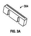
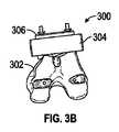
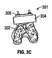
図3Aから図3Dは、いくつかの例による遠位切削ブロックシステム(例えば300、301、または303)を概略的に示す図である。一例では、一般的な切削ブロックは、第1の切削ブロックまたは遠位切削ブロックを含むことができる。一例では、図3Aは、遠位切削ブロック304を示す図である。図3Bは、遠位切削ブロックシステム300内における遠位切削ブロック304を示す図である。一例では、図3Bの遠位切削ブロックシステム300は、前切削ブロック306(例えば遠位位置決め構成要素202によって配置された図2の前方位置決めブロック204)と、骨302とを含む。遠位切削ブロック304は、前方位置決めブロック304を配置するために使用される遠位位置決め構成要素の位置と重複する、骨302に対する位置に配置することができる。例えば、遠位位置決め構成要素は、前方位置決めブロック304を配置するために使用した後で除去し、その後に、図3Bに示すように遠位切削ブロック306を配置することができる。遠位切削ブロック306は、図3Cの遠位切削ブロックシステム301に示すように、遠位切削を行うために使用することができる。 3A-3D schematically illustrate a distal cutting block system (eg, 300, 301, or 303) according to some examples. In one example, a typical cutting block can include a first cutting block or a distal cutting block. In one example, FIG. 3A shows a
一例では、遠位位置決め構成要素を除去した後で、遠位切削ブロック306を、残っている前方位置決めブロック304に取り付けることができる。この遠位切削ブロック306を使用して、遠位切削を行うことができる。図3Dの遠位切削ブロックシステム303に示すように、遠位切削を行った後で、遠位切削ブロック306を除去することができる。前方位置決めブロック304は、適所に留まることができる。一例では、図3Cおよび図3Dに示すように、遠位切削ブロック306を使用して、骨上の係合フィーチャの周りの領域を除去する遠位切削を行うことができる。 In one example, the
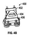
図4Aから図4Bは、いくつかの例による万能アダプタ404および4−in−1切削ブロック406を概略的に示す図である。図4Aは、図4Bの切削ブロックシステム400で使用することができる万能アダプタ404を示す図である。万能アダプタ404を使用して、図4Bに示すように、4−in−1切削ブロック406を前方位置決めブロック402に取り付けることができる。万能アダプタ404を使用して、標準的な4−in−1切削ブロック(例えば4−in−1切削ブロック406)を、前方位置決めブロック402に取り付けることができる。一例では、4−in−1切削ブロック406を取り付ける前に、大腿骨ペグ穴の位置付けを行うことができる。別の例では、外科医が、この時点で、切削ブロックシステム400を使用して、インプラントのML位置決めを精細に調整することができる。一例では、万能アダプタ404は、外科医が4−in−1切削ブロック406を位置決めするのを補助する一方で、万能アダプタ404のタブと対合する近位表面の溝に沿って4−in−1切削ブロックを滑動させることによって、ML位置決めの調節も可能にしている。4−in−1切削ブロック406は、ペグ穴ロケータまたはウィングピンホールを介してねじまたはピンによって取り付けることができる。例えば、遠位位置決め構成要素および4−in−1切削ブロックは、骨に開いた穴を骨への取付けに再利用することができる。 4A-4B schematically illustrate a
一例では、骨または構成要素の穴を使用して構成要素またはブロックを骨に接続することにより、その構成要素またはブロックを骨と確動係合させることができる。これにより、その後の骨の切削の精度を向上させることができる。例えば、構成要素またはブロックを、骨に緩く嵌合させ、その後、その構成要素またはブロックを骨に対してねじ止めまたはピン止めすることによって、正確な係合位置に締結することができる。 In one example, a bone or component hole can be used to positively engage the component or block with the bone by connecting the component or block to the bone. Thereby, the precision of subsequent bone cutting can be improved. For example, a component or block can be tightened into the correct engagement position by loosely fitting the bone or bone and then screwing or pinning the component or block to the bone.
前方位置決めブロック402および万能アダプタ404は、4−in−1切削ブロック406が固定された、または取り付けられた後で、除去することができる。一例では、万能アダプタ404または4−in−1切削ブロック406は、遠位切削ブロックまたは遠位位置決め構成要素によって以前は占められていた領域のうちの1つまたは複数の一部分と重複する位置に、骨に対して相対的に位置決めすることができる。例えば、遠位切削ブロック、遠位位置決め構成要素、万能アダプタ、または4−in−1切削ブロック406のうちの2つ以上を、前方位置決めブロック402の同じ面に取り付けることができる。 The
別の例では、大腿骨は、さらなる大幅な時間短縮をもたらすことができるナビゲートされる穴を使用して準備することができる。ナビゲートされる穴を使用することによって、標準的な手順から、従来のIM遠位切削装置を使用するステップ、大腿骨サイザ装置を使用するステップ、または切削位置ブロックの位置を決定するステップなどのステップを省略することができる。 In another example, the femur can be prepared using a navigated hole that can provide further significant time savings. By using a navigated hole, from a standard procedure, such as using a conventional IM distal cutting device, using a femoral sizer device, or determining the position of a cutting position block, etc. Steps can be omitted.
さらに別の例では、記載する方法およびシステムは、最小侵襲手術(MIS)の人工膝関節全置換(TKR)で使用することができる。例えば、位置決めブロックまたは位置決め構成要素は、内側または外側の位置決めブロックまたは位置決め構成要素を含むことができる。位置決めブロックまたは構成要素は、MIS TKRで使用するように設計することができる、または通常のTKRで使用されるものを修正せずに使用することができる。MIS TKRは、筋肉を避ける(例えば筋肉温存)ために使用される、または最小の関節切開長を使用するときに使用される位置決めブロックまたは構成要素を含むことができる。典型的ではない非MISの手順では、本明細書に記載するデバイス、構成要素、ブロックなどは、特殊な状況で使用するように修正することができる。例えば、外転した膝蓋骨または通常の関節切開長が手順にない場合には、これらの構成要素、ブロック、デバイス、切削部などのうちの1つまたは複数を、外科手術の助けになるように修正することができる。 In yet another example, the methods and systems described can be used in minimally invasive surgery (MIS) total knee replacement (TKR). For example, the positioning block or positioning component can include an inner or outer positioning block or positioning component. The positioning block or component can be designed for use in MIS TKR, or can be used without modification to that used in normal TKR. The MIS TKR can include positioning blocks or components that are used to avoid muscles (eg, muscle preservation) or are used when using minimal arthrotomy lengths. In non-typical non-MIS procedures, the devices, components, blocks, etc. described herein can be modified for use in special situations. For example, if an abducted patella or normal arthrotomy length is not in the procedure, modify one or more of these components, blocks, devices, cuttings, etc. to aid in surgery can do.
本明細書に記載する様々な構成要素、ブロック、デバイス、器具などは、再利用するものであってもよいし、1回使用した後で使い捨てにするものであってもよい。例えば、前方位置決めブロック、遠位位置決め構成要素、遠位切削ブロック、4−in−1切削ブロック、万能アダプタ、脛骨切削ブロック、脛骨プレートトライアル、またはナビゲーションポジショナのうちの1つまたは複数を使い捨てにして1回しか使用しないようにしてもよいし、あるいは再利用するようにしてもよい。一例では、本明細書に記載する構成要素、ブロックなどのうちの1つまたは複数は、変形可能な材料を含むことができる。例えば、構成要素またはブロックを、屈曲変位によって骨との確動係合を可能にするばね状の材料(例えばゴム、プラスティックなど)で構成することができる。一例では、構成要素またはブロックは、単一の一体構成要素またはブロックとして製造または作製することができる。別の例では、構成要素またはブロックは、複数部分(例えば、結合されて1つの構成要素またはブロックとなる2つの部分)で製造または作製することができる。1つの脛骨構成要素を複数部分で製造または作製することにより、骨への確動またはロック接続を容易にすることができる。製造または作製は、従来の製造、3D印刷、彫刻などを含むことができる。 Various components, blocks, devices, instruments, etc. described herein may be reused or disposable after a single use. For example, one or more of an anterior positioning block, a distal positioning component, a distal cutting block, a 4-in-1 cutting block, a universal adapter, a tibial cutting block, a tibial plate trial, or a navigation positioner may be disposable It may be used only once or may be reused. In one example, one or more of the components, blocks, etc. described herein can include a deformable material. For example, the component or block can be constructed of a spring-like material (eg, rubber, plastic, etc.) that allows positive engagement with the bone by bending displacement. In one example, the components or blocks can be manufactured or made as a single unitary component or block. In another example, a component or block can be manufactured or made in multiple parts (eg, two parts that are combined into a single component or block). Manufacturing or making a tibial component in multiple parts can facilitate positive or locking connections to the bone. Manufacturing or fabrication can include conventional manufacturing, 3D printing, engraving, and the like.
一例では、ナビゲーション手順を使用することによって追加される可能性がある追加の手術室(OR)時間は、NAVIO(登録商標)の最適化された器具を使用することによって補償することができる。本明細書に記載する方法およびシステムは、事前手順撮像、あるいは特定患者用切削ガイドまたは特定患者用インプラントを使用しない「特定患者用」膝関節移植を含み得る。 In one example, additional operating room (OR) time that may be added by using a navigation procedure can be compensated for by using NAVIO® optimized instruments. The methods and systems described herein may include pre-procedural imaging or “specific patient” knee implants that do not use specific patient cutting guides or specific patient implants.
図5Aから図5Bは、いくつかの例による脛骨切削ブロック(例えば504Aまたは504B)を概略的に示す図である。一例では、脛骨準備は、大腿骨(またはその他の骨)について上述したのと同様の方法で、同様のシステムを使用して行うことができる。脛骨準備では、インプラントは、計画段階中にNAVIO(登録商標)ソフトウェアを使用して予め位置決めすることができる。NAVIO(登録商標)ソフトウェアを使用すると、最もよく適合するインプラントのサイズおよび位置を使用して切削面を決定することができる。 5A-5B schematically illustrate a tibial cutting block (eg, 504A or 504B) according to some examples. In one example, tibial preparation can be performed using a similar system in a manner similar to that described above for the femur (or other bone). In tibial preparation, the implant can be pre-positioned using the NAVIO® software during the planning phase. Using NAVIO® software, the cutting surface can be determined using the best fit implant size and position.
一例では、NAVIO(登録商標)システムは、脛骨切削ブロック(例えば504Aまたは504B)の位置の正しい後傾角を実現する骨502の単純なバー処理領域(例えば、脛骨上の3つまたは4つのバー領域あるいはゾーン生成係合フィーチャ)を決定することができる。任意のサイズのインプラントについて、単一の左(L)または右(R)のカッタを使用することができる。図5Aに示すように、脛骨切削システム500は、骨502(例えば脛骨)、および脛骨切削ブロック504Aを含むことができる。その他のタイプの脛骨切削ブロックを使用することもできる(例えば図5Bに示す504B)。別の例では、一体化型の位置決めおよび切削ガイドブロックを、位置決めおよび位置付けに使用することができる。 In one example, the NAVIO® system is a simple bar processing area (eg, 3 or 4 bar areas on the tibia) that provides the correct posterior tilt of the position of the tibial cutting block (eg, 504A or 504B). Alternatively, the zone generation engagement feature) can be determined. A single left (L) or right (R) cutter can be used for any size implant. As shown in FIG. 5A, the
一例では、位置的バー切削を行って係合フィーチャを作成した後で、脛骨切削ブロック(例えば504Aまたは504B)を目立たないように脛骨上に配置することができる。脛骨切削ブロック(例えば504Aまたは504B)は、頭付きまたは頭無しピンを用いて適所にピン止めして、その後の骨切削動作中にガイドを固定することができる。脛骨切削ブロック(例えば504Aまたは504B)を使用して脛骨切削を行った後で、適当な厚さの脛骨トライアルプレートまたは適当なポリエチレンインサートトライアルを使用して、適当な膝関節の伸展ギャップまたは屈曲ギャップがないかどうか検査することができる。一例では、脛骨切削ブロック(例えば504Aまたは504B)は、脛骨トライアルプレートまたはポリエチレンインサートトライアルを設置する前に除去することができる。一例では、システムを再位置決めすることによって傾斜角を変更することができる。このシステムを再切削手順に再利用することもできるし、あるいは、特殊な再切削用脛骨切削ブロックを使用して、切削深さを増大させる、または脛骨切削部の後傾を変化させることもできる。 In one example, a tibial cutting block (eg, 504A or 504B) can be placed inconspicuously on the tibia after positional bar cutting has been performed to create the engagement feature. The tibial cutting block (eg, 504A or 504B) can be pinned in place with a headed or headless pin to secure the guide during subsequent bone cutting operations. After tibial cutting using a tibial cutting block (eg, 504A or 504B), use the appropriate thickness of the tibial trial plate or the appropriate polyethylene insert trial to use the appropriate knee extension or flexion gap. Can be inspected for In one example, the tibial cutting block (eg, 504A or 504B) can be removed prior to installing the tibial trial plate or polyethylene insert trial. In one example, the tilt angle can be changed by repositioning the system. The system can be reused for recutting procedures, or a special recutting tibial cutting block can be used to increase the cutting depth or to change the posterior tilt of the tibial cut. .
インプラントの幾何学的形状、特に大腿骨およびポリエチレンインサートインプラントの関節面をデータベースを介してCASシステムが知ることができるので、脛骨の構成要素(脛骨プレートまたはポリエチレンインサート)のML回転またはAP回転を、切除後の脛骨上で位置合わせすることができる。例えば、この位置合わせは、歩行運動中に大腿骨または脛骨の構成要素の不一致が生じないように、大腿骨インプラントに対する最もよく適合する位置を含むことができる。 Since the CAS system can know the implant geometry, in particular the femoral and polyethylene joint implant joint surfaces via a database, ML or AP rotation of the tibial component (tibial plate or polyethylene insert) It can be aligned on the tibia after resection. For example, this alignment can include a best-fit position for the femoral implant so that there are no femoral or tibial component mismatches during walking motion.
膝の伸展中には、大腿骨およびポリエチレンインサートの関節面を適切に位置合わせすることが特に重要である。位置合わせが不適切であると、内側および外側の区画の荷重が非対称になり、それにより患者が不快感を覚えたり、膝の位置が突然変化したり、またはポリエチレンの摩耗速度が速くなったりする恐れがある。非対称な荷重は、また、接着された構成要素が骨から緩む可能性を生じる恐れもある。 During knee extension, it is particularly important to properly align the articulating surfaces of the femur and the polyethylene insert. Improper alignment can cause the inner and outer compartment loads to become asymmetric, which can cause patient discomfort, sudden knee changes, or increased polyethylene wear rates. There is a fear. Asymmetric loads can also cause the bonded components to loosen from the bone.
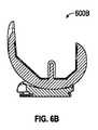
図6Aから図6Bは、いくつかの例による適切に配置された大腿骨インプラント(例えば600Aまたは600B)を概略的に示す図である。図6AのML断面図に示すように、また図6BのAP図に示すように、伸展状態の通常の大腿骨インプラントは、理想的には、ポリエチレンインサート上に位置付けることができる。図6Aおよび図6Bは、脚が重量を支承する伸展位置にあるときの、大腿骨構成要素と脛骨構成要素の間の所望の関係を示している。 6A-6B schematically illustrate a properly placed femoral implant (eg, 600A or 600B) according to some examples. As shown in the ML cross-sectional view of FIG. 6A and as shown in the AP view of FIG. 6B, a stretched normal femoral implant can ideally be positioned on a polyethylene insert. 6A and 6B illustrate the desired relationship between the femoral and tibial components when the leg is in the extended position to support weight.
図7は、いくつかの例による、不適切に配置された大腿骨インプラント(例えば、700A、700B、700C、700D、または700E)を概略的に示す図である。図7の様々な例は、相対的なインプラント位置の任意の異常回転が、ポリエチレンインサートの荷重が増大した局所領域と、その結果として生じる歩行運動中の患者の大腿骨に対する脛骨の異常回転(外側または内側)とを生じ、その結果として、ポリエチレンインサートの異常摩耗を生じ、患者に痛みまたは不快感を覚えさせる可能性があることを示している。 FIG. 7 schematically illustrates an improperly positioned femoral implant (eg, 700A, 700B, 700C, 700D, or 700E), according to some examples. The various examples in FIG. 7 show that any abnormal rotation of the relative implant position is caused by localized rotation of the polyethylene insert and the resulting abnormal rotation of the tibia relative to the patient's femur during gait movement (outside Or inside), which results in abnormal wear of the polyethylene insert, which can cause the patient to feel pain or discomfort.
図8は、いくつかの例による脛骨プレートトライアル804およびナビゲーションポジショナ806を概略的に示す図である。脛骨プレートの位置決め誤差が生じる可能性を最小限に抑えるのを助けるために、ナビゲーションシステムを使用して、ナビゲートされるポジショナ806を、脛骨インプラント配置システム800の脛骨キールのための脛骨802の穿孔を行う前に、脛骨プレートトライアル804に取り付けることができる。ピン808を使用して、脛骨プレートトライアル804を脛骨802に取り付けることができる。一例では、脛骨切削ガイドを固定するために既に配置されているピンを使用して、脛骨プレートの位置決め誤差が生じる可能性を最小限に抑えることができる。例えば、ナビゲートされるバーゾーンは、切削ガイドを位置付け、ピン位置を決定するために使用されているが、これを、脛骨プレートトライアルおよびこれらのピンの両方とのインタフェースとなる誘導デバイスと関連付けて使用することができる。これにより、ナビゲーション計画ごとに脛骨プレートトライアルのML回転配向を設定することができる。AP位置は、脛骨(例えばポリエチレン)インサート位置のヌル点を大腿骨インプラントの伸展位置と整列するように位置決めすることができる脛骨プレート上の既知の基準上にスタイラスを配置することによって確認することができる。 FIG. 8 schematically illustrates a
さらに別の例では、最前バーゾーンを、脛骨プラトー中でわずかにより深くすることができる。これにより、脛骨切削を行った後でも、バーゾーンが見えるようにすることができる。バーゾーンを使用して、AP位置のトライアル脛骨プレートの前縁部を識別することもできる。このことと、ピン配置によって決定されるMLまたは回転配置とが相まって、トライアル脛骨プレートを、脛骨上の最適な位置に、大腿骨上に以前に位置付けられた大腿骨トライアルに対して、位置付けることができる。その結果として、インプラントと、したがって大腿骨および脛骨とを、互いに対して理想的な位置にして、患者の快適さを最大限に高め、膝およびインプラントの機能を最大限に高めることができる。 In yet another example, the forefront bar zone can be slightly deeper in the tibial plateau. Thereby, even after performing tibial cutting, the bar zone can be made visible. The bar zone can also be used to identify the leading edge of the trial tibial plate at the AP location. This, coupled with ML or rotational placement determined by pin placement, allows the trial tibial plate to be positioned in an optimal position on the tibia relative to the femoral trial previously located on the femur. it can. As a result, the implant, and thus the femur and tibia, can be in an ideal position relative to each other to maximize patient comfort and maximize knee and implant function.
図1Aから図5Bに示して上述した例では、位置決め構成要素の一部(例えば前方位置決めブロックまたは遠位位置決め構成要素)は、使用中に互いに結合して完成した位置決め構成要素またはガイドを形成する複数の対合構成要素を含むものとして述べている。いくつかの例では、骨に機械加工された係合フィーチャにパチッと嵌まり込む変形可能な(例えばばね状の)材料で作製することができる一体型の位置決め構成要素を使用する。一体型位置決め構成要素または多部品位置決め構成要素などの上述の計装および技術の適用形態は、特定の手順または対象とする関節(例えば肘関節、股関節、肩関節など)の要件に応じて、特定の方法で修正することができる。 In the example shown in FIGS. 1A-5B and described above, portions of the positioning component (eg, an anterior positioning block or a distal positioning component) are coupled together during use to form a completed positioning component or guide. It is described as including a plurality of mating components. Some examples use an integral positioning component that can be made of a deformable (eg, spring-like) material that snaps into engagement features machined into the bone. The instrumentation and technology applications described above, such as integral positioning components or multi-part positioning components, are specific depending on the specific procedure or requirements of the target joint (eg elbow joint, hip joint, shoulder joint, etc.) It can be corrected with this method.
上述の例では、位置決め構成要素または切削ガイドを、前方位置決めブロックなど、特定の計装品がその例示的な手順でどのように使用されるかを示すことができる具体的な名称で呼んでいることもある。これらの具体的な名称は、単に、そこで説明している例示的な手順において、さらに分かりやすくするために使用しているものである。説明した係合フィーチャを作成するための位置決め構成要素の概念および関連する器具は、様々な解剖学的位置における骨または軟組織の切除を含むその他の手順にも適用可能である。 In the above example, the positioning component or cutting guide is referred to by a specific name that can indicate how a particular instrument is used in its exemplary procedure, such as a forward positioning block. Sometimes. These specific names are merely used for clarity in the exemplary procedures described therein. The positioning component concepts and associated instruments for creating the described engagement features are applicable to other procedures including bone or soft tissue resection at various anatomical locations.
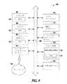
図9は、本明細書に記載する方法の任意の1つまたは複数をコンピュータシステムに実行させる命令をその内部で実行することができるコンピュータシステム900の形態のマシンのブロック図の一例を示すブロック図である。様々な実施形態で、このマシンは、独立型デバイスとして動作することもできるし、あるいは他のマシンに接続する(例えばネットワーク化する)こともできる。ネットワーク型の配備では、マシンは、サーバクライアントネットワーク環境のサーバまたはクライアントマシンの容量内で、あるいはピアツーピア(または分散型)ネットワーク環境のピアマシンとして、動作することができる。このマシンは、パーソナルコンピュータ(PC)、タブレットPC、セットトップボックス(STB)、PDA、携帯電話、ウェブアプライアンス、ネットワークルータ、スイッチまたはブリッジ、あるいはそのマシンが行う動作を指定する命令(逐次またはその他)を実行することができる任意のマシンとすることができる。さらに、図示しているマシンは1つだけであるが、「マシン」という用語は、本明細書に記載する方法の任意の1つまたは複数を実行する命令の1つまたは複数のセットを個別に、または協働して実行する、任意のマシンの集合を含むものとして解釈されるものとする。 FIG. 9 is a block diagram illustrating an example of a block diagram of a machine in the form of a
この例示的なコンピュータシステム900は、バス908を介して互いに通信する、プロセッサ902(中央処理装置(CPU)もしくはグラフィック処理装置(GPU)またはその両方など)、主メモリ904、および静的メモリ906を含む。コンピュータシステム900は、さらに、ビデオ表示装置910(液晶ディスプレイ(LCD)または陰極線管(CRT)など)、英数字入力デバイス912(キーボードなど)、ユーザインタフェース(UI)ナビゲーションデバイス(またはカーソル制御デバイス)914(マウスなど)、ディスクドライブ装置916、信号生成デバイス918(例えばスピーカ)、およびネットワークインタフェースデバイス920を含むことができる。 The
ディスクドライブ装置916は、1組または複数組の命令のセットを記憶する機械可読記憶媒体922と、本明細書に記載する方法または機能の任意の1つまたは複数を実施する、またはそれらによって使用されるデータ構造(例えばソフトウェア)924とを含む。これらの命令924は、機械可読媒体をも構成するコンピュータシステム900、主メモリ904およびプロセッサ900による実行時には、完全に、または少なくとも部分的に、主メモリ904内、静的メモリ906内、またはプロセッサ902内に存在することもできる。一例では、機械可読記憶媒体922に記憶された命令924は、コンピュータシステム900に、骨の特定患者用モデルを決定させ、コンピュータ制御された切削器具を使用して、この特定患者用モデルを使用して骨に係合フィーチャを準備させる命令を含む。これらの命令924は、また、コンピュータシステム900に、骨上に係合フィーチャを準備するために使用される仮想モデルを作成させる命令924も含むことができる。機械可読記憶媒体922は、さらに、コンピュータシステム900にコンピュータ援用外科手術(CAS)システムを操作させる命令924を記憶することができる。 The
例示的な実施形態では、機械可読媒体922が単一の媒体であるものとして示しているが、「機械可読媒体」という用語は、1つまたは複数の命令またはデータ構造を記憶する1つまたは複数の媒体(例えば、集中型または分散型データベース、ならびに/あるいは関連するキャッシュおよびサーバ)を含み得る。「機械可読記憶媒体」という用語も、本発明の方法の任意の1つまたは複数をマシンに実行させるマシンによって実行される命令を記憶、符号化、または搬送することができる、あるいはこれらの命令によって使用される、またはこれらの命令と関連付けて使用されるデータ構造を記憶、符号化、または搬送することができる、任意の有形媒体を含むものとして解釈されるものとする。「機械可読記憶媒体」という用語は、したがって、固体状態メモリ、ならびに光媒体および磁気媒体を含む(ただしこれらに限定されない)ものとして解釈されるものとする。機械可読媒体の具体例としては、例えば半導体メモリデバイス(例えば消去可能プログラマブル読取り専用メモリ(EPROM)、電気的消去可能プログラマブル読取り専用メモリ(EEPROM))およびフラッシュメモリデバイスなどの不揮発性メモリ、内蔵ハードディスクおよび取外し可能ディスクなどの磁気ディスク、磁気光ディスク、ならびにCD−ROMおよびDVD−ROMディスクなどが挙げられる。「機械可読記憶媒体」は、特にレジスタメモリ、プロセッサキャッシュ、およびRAMなど、一時的と解釈することができるデバイスも含むものとする。本明細書に与える機械可読媒体および機械可読記憶媒体の定義は、さらに機械可読媒体が「非一時的」であることを特徴とする場合でも適用可能である。例えば、非一時的機械可読記憶媒体など、「非一時的」という言葉が追加されている場合も、依然として、メモリデバイスの中でも特に、レジスタメモリ、プロセッサキャッシュ、およびRAMを包含するものと意図されている。 In the exemplary embodiment, machine-readable medium 922 is shown as being a single medium, but the term “machine-readable medium” refers to one or more that stores one or more instructions or data structures. Media (eg, centralized or distributed databases, and / or associated caches and servers). The term “machine-readable storage medium” can also store, encode, or carry instructions executed by a machine that causes the machine to perform any one or more of the methods of the present invention. It shall be construed as including any tangible medium that can store, encode, or carry data structures used or associated with these instructions. The term “machine-readable storage medium” is therefore to be interpreted as including, but not limited to, solid state memory and optical and magnetic media. Specific examples of machine readable media include, for example, semiconductor memory devices (eg, erasable programmable read only memory (EPROM), electrically erasable programmable read only memory (EEPROM)) and non-volatile memory such as flash memory devices, internal hard disks and Examples include magnetic disks such as removable disks, magnetic optical disks, and CD-ROM and DVD-ROM disks. "Machine-readable storage medium" also includes devices that can be interpreted as temporary, particularly register memory, processor cache, and RAM. The definitions of machine-readable media and machine-readable storage media provided herein are also applicable when the machine-readable media are further characterized as “non-transitory”. Where the term “non-transitory” is added, eg, non-transitory machine-readable storage media, it is still intended to encompass register memories, processor caches, and RAM, among other memory devices. Yes.
様々な例で、命令924は、さらに、伝送媒体を使用して通信ネットワーク926を介して送信または受信することができる。命令924は、ネットワークインタフェースデバイス920と、いくつかの周知の転送プロトコル(例えばHTTP)のうちの任意の1つとを使用して伝送することができる。通信ネットワークの例としては、LAN、WAN、インターネット、携帯電話網、基本電話サービス(POTS)ネットワーク、およびワイヤレスデータネットワーク(例えばWi−FiおよびWiMAXネットワーク)などが挙げられる。「伝送媒体」という用語は、マシンによって実行される命令を記憶、符号化、または搬送することができる任意の無形の媒体を含み、このようなソフトウェアの通信を容易にするデジタルまたはアナログ通信信号あるいはその他の無形の媒体を含むものとして解釈されるものとする。 In various examples,
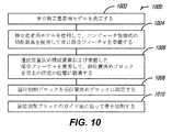
図10は、いくつかの例による骨の整形外科手術に使用されるシステムを動作させる方法1000を示す流れ図である。方法1000は、骨の特定患者用モデルを決定する動作1002と、特定患者用モデルを使用して、コンピュータ制御式の切削器具を使用して骨に係合フィーチャを準備する動作1004とを含むことができる。方法1000は、遠位位置決め構成要素(例えば遠位位置決め構成要素202)および準備した係合フィーチャ(例えば係合フィーチャ102)を使用して、前方位置決めブロック(例えば前方位置決めブロック204)を骨上の所定の位置に誘導する動作1006を含むことができる。一例では、遠位位置決め構成要素は、前方位置決めブロックに取り付けることができる。方法1000は、前方位置決めブロックが対象の骨に取り付けられた後で、遠位位置決め構成要素を取り外すステップを含むことができる。 FIG. 10 is a flow diagram illustrating a method 1000 for operating a system used in bone orthopedic surgery according to some examples. Method 1000 includes an
方法1000は、遠位切削ブロック(例えば遠位切削ブロック304)を前方位置決めブロックに固定する動作10008を含むことができる。一例では、遠位切削ブロックは、遠位位置決め構成要素が取り外された後で、前方位置決めブロックに固定することができる。遠位切削ブロックおよび遠位位置決め構成要素を固定する位置は重複していてもよい。例えば、遠位切削ブロックおよび遠位位置決め構成要素が重複した位置に固定されているとき、一度に一方のみを前方位置決めブロックに取り付ける、または固定することもできる。 Method 1000 can include an act 10008 of securing a distal cutting block (eg, distal cutting block 304) to a front positioning block. In one example, the distal cutting block can be secured to the front positioning block after the distal positioning component has been removed. The positions for securing the distal cutting block and the distal positioning component may overlap. For example, when the distal cutting block and the distal positioning component are secured in overlapping positions, only one can be attached or secured to the front positioning block at a time.
方法1000は、遠位切削ブロックのガイド面に沿って骨を切削する動作1010を含むことができる。一例では、方法1000は、ガイド面に沿って骨を切削した後で遠位切削ブロックを取り外すステップと、万能アダプタ(例えば万能アダプタ404)を使用して4−in−1切削ブロック(例えば4−in−1切削ブロック406)を前方位置決めブロックに取り付けるステップと、4−in−1切削ブロックのガイド面に沿って骨を切削するステップとを含む。 The method 1000 can include an act of cutting 1010 along the guide surface of the distal cutting block. In one example, the method 1000 includes removing a distal cutting block after cutting bone along a guide surface and using a universal adapter (eg, universal adapter 404) to create a 4-in-1 cutting block (eg, 4-in-1). attaching the in-1 cutting block 406) to the anterior positioning block and cutting bone along the guide surface of the 4-in-1 cutting block.
図11は、いくつかの例による、骨の整形外科手術に使用されるシステムを動作させる方法1100を示す流れ図である。方法1100は、骨の特定患者用モデルを決定する動作1102と、特定患者用モデルを使用して、コンピュータ制御式の切削器具を使用して骨に係合フィーチャを準備する動作1104とを含むことができる。方法1100は、準備した係合フィーチャを使用して、脛骨切削ブロック(例えば脛骨切削ブロック504Aまたは504B)を骨の所定の位置に取り付ける動作1106を含むことができる。方法1100は、脛骨切削ブロックのガイド面に沿って骨を切削する動作1108を含むことができる。方法1100を使用して、脛骨トライアルプレートを配置し、必要な場合には骨を再切削することができる。脛骨切削ブロックを再利用して骨を再切削することもできるし、あるいは、新たな再切削脛骨ブロックを使用して骨を再切削することもできる。一例では、切削および必要な場合には再切削の後で、ポリエチレンインサートを骨に取り付けることができる。別の例では、ナビゲートされるポジショナ(例えばナビゲートされるポジショナ806)を脛骨トライアルプレート(例えば脛骨トライアルプレート804)に取り付けて、適当な膝関節の伸展ギャップまたは屈曲ギャップを決定することができる。 FIG. 11 is a flow diagram illustrating a method 1100 for operating a system used in bone orthopedic surgery, according to some examples. Method 1100 includes an
様々な注釈および例
これらの非限定的な例はそれぞれ、単独で成立することもできるし、あるいは様々な順列または組合せで、他の例のうちの1つまたは複数と結合することもできる。Various Annotations and Examples Each of these non-limiting examples can stand alone or can be combined with one or more of the other examples in various permutations or combinations.
例1は、対象の骨の手術に使用される整形外科手術デバイスであって、1次位置決めブロックと、前記1次位置決めブロックに取外し可能に結合される2次位置決め構成要素であり、前記対象の骨に機械加工された準備された係合フィーチャと係合し、前記1次位置決めブロックを対象の骨上の所定の位置に誘導するように構成された2次位置決め構成要素と、前記1次位置決めブロックと取外し可能に結合し、切削工具を誘導して前記対象の骨を切削するように構成された第1の切削ブロックとを含む、整形外科手術デバイスによって実施される主題を含む。 Example 1 is an orthopedic surgical device used for surgery on a bone of a subject, comprising a primary positioning block and a secondary positioning component that is removably coupled to the primary positioning block, A secondary positioning component configured to engage a prepared engagement feature machined into bone and to guide the primary positioning block to a predetermined position on the target bone; and the primary positioning And a first cutting block removably coupled to the block and configured to guide a cutting tool to cut the bone of interest.
例2では、例1の主題は、任意選択で、前記準備された係合フィーチャが、仮想モデルを使用して作成されることを含むことができる。 In Example 2, the subject matter of Example 1 can optionally include the prepared engagement feature being created using a virtual model.
例3では、例1から例2の1つまたは任意の組合せの主題は、任意選択で、前記仮想モデルが、前記対象の骨の特定患者用仮想モデルを含むことを含むことができる。 In Example 3, the subject matter of one or any combination of Examples 1 to 2 can optionally include that the virtual model includes a specific patient virtual model of the subject bone.
例4では、例1から例3の1つまたは任意の組合せの主題は、任意選択で、前記1次位置決めブロックに取外し可能に結合される4−in−1切削ブロックをさらに含むことができる。 In Example 4, the subject matter of one or any combination of Examples 1 to 3 can optionally further include a 4-in-1 cutting block that is removably coupled to the primary positioning block.
例5では、例1から例4の1つまたは任意の組合せの主題は、任意選択で、前記4−in−1切削ブロックが、前記2次位置決め構成要素が取り外された後で、前記1次位置決めブロックに結合されることを含むことができる。 In Example 5, the subject matter of one or any combination of Examples 1 to 4 is optionally that the 4-in-1 cutting block is the primary after the secondary positioning component is removed. Can be coupled to the positioning block.
例6では、例1から例5の1つまたは任意の組合せの主題は、任意選択で、前記4−in−1切削ブロックが、前記2次位置決め構成要素または前記第1の切削ブロックの位置と少なくとも部分的に重複する構成で、前記1次位置決めブロックに取外し可能に結合するように構成されることを含むことができる。 In Example 6, the subject matter of one or any combination of Examples 1 to 5 is optionally that the 4-in-1 cutting block is positioned with the position of the secondary positioning component or the first cutting block. It may include being configured to be removably coupled to the primary positioning block in an at least partially overlapping configuration.
例7では、例1から例6の1つまたは任意の組合せの主題は、任意選択で、前記4−in−1切削ブロックが、万能アダプタを使用して、前記1次位置決めブロックに取外し可能に結合されることを含むことができる。 In Example 7, the subject matter of one or any combination of Examples 1 to 6 is optionally that the 4-in-1 cutting block can be removed from the primary positioning block using a universal adapter. Can be combined.
例8では、例1から例7の1つまたは任意の組合せの主題は、任意選択で、前記4−in−1切削ブロックが、複数の切削を誘導するようにさらに構成されることを含むことができる。 In Example 8, the subject matter of one or any combination of Examples 1 to 7 optionally includes that the 4-in-1 cutting block is further configured to guide a plurality of cuts. Can do.
例9では、例1から例8の1つまたは任意の組合せの主題は、任意選択で、前記4−in−1切削ブロックが、前記1次位置決めブロックおよび前記万能アダプタが取り外されたときに前記複数の切削を誘導するように構成されることを含むことができる。 In Example 9, the subject matter of one or any combination of Examples 1 to 8 is that the 4-in-1 cutting block is optionally configured when the primary positioning block and the universal adapter are removed. Can be configured to guide a plurality of cuts.
例10では、例1から例9の1つまたは任意の組合せの主題は、任意選択で、前記2次位置決め構成要素および前記第1の切削ブロックが、部分的に重複する位置で前記前方位置決めブロックに取外し可能に結合するように構成されることを含むことができる。 In Example 10, the subject matter of one or any combination of Examples 1-9 is optionally the front positioning block at a position where the secondary positioning component and the first cutting block partially overlap Configured to be removably coupled to the device.
例11では、例1から例10の1つまたは任意の組合せの主題は、任意選択で、前記2次位置決め構成要素、前記第1の切削ブロック、および前記1次位置決めブロックが、特定患者用ではないことを含むことができる。 In Example 11, the subject of one or any combination of Examples 1-10 is optionally that the secondary positioning component, the first cutting block, and the primary positioning block are for a particular patient. Can be included.
例12では、例1から例11の1つまたは任意の組合せの主題は、任意選択で、前記1次位置決めブロックが、前方位置決めブロックであり、前記2次位置決め構成要素が、遠位位置決め構成要素であり、前記第1の切削ブロックが、遠位切削ブロックであることを含むことができる。 In Example 12, the subject of one or any combination of Examples 1 to 11 is optionally that the primary positioning block is a front positioning block and the secondary positioning component is a distal positioning component. And wherein the first cutting block is a distal cutting block.
例13は、関節の骨をインプラントのために準備するシステムであって、前記骨に係合フィーチャを準備するように構成されたコンピュータ制御式の切削器具と、前記準備された係合フィーチャと係合するように構成された位置決め固定具であり、1次位置決めブロック、および前記1次位置決めブロックに取外し可能に結合される2次位置決め構成要素を含む位置決め固定具と、前記1次位置決めブロックと取外し可能に結合し、切削工具を誘導して前記骨を切削するように構成された第1の切削ブロックとを含む、システムによって実施される主題を含む。 Example 13 is a system for preparing a bone of a joint for an implant, the computer-controlled cutting instrument configured to prepare an engagement feature on the bone, and the engagement of the prepared engagement feature. A positioning fixture configured to mate, including a primary positioning block and a secondary positioning component removably coupled to the primary positioning block; and the primary positioning block and removal A system-implemented subject matter including a first cutting block that is operatively coupled and configured to guide a cutting tool to cut the bone.
例14では、例13の主題は、任意選択で、万能アダプタを使用して前記1次位置決めブロックに取外し可能に結合し、第2の切削工具を誘導して前記骨を切削するように構成された4−in−1切削ブロックをさらに含むことを含むことができる。 In Example 14, the subject of Example 13 is optionally configured to removably couple to the primary positioning block using a universal adapter and guide a second cutting tool to cut the bone. Further including a 4-in-1 cutting block.
例15では、例13から例14の1つまたは任意の組合せの主題は、任意選択で、前記準備された係合フィーチャが、仮想モデルを使用して作成されることを含むことができる。 In Example 15, the subject matter of one or any combination of Examples 13 through 14 can optionally include the prepared engagement feature being created using a virtual model.
例16では、例13から例15の1つまたは任意の組合せの主題は、任意選択で、前記骨が、大腿骨であることを含むことができる。 In Example 16, the subject matter of one or any combination of Examples 13-15 can optionally include that the bone is a femur.
例17では、例13から例16の1つまたは任意の組合せの主題は、任意選択で、前記コンピュータ制御式の切削器具が、コンピュータ援用外科手術(CAS)システムによって制御されることを含むことができる。 In Example 17, the subject matter of one or any combination of Examples 13 to 16 optionally includes that the computer-controlled cutting instrument is controlled by a computer-aided surgical (CAS) system. it can.
例18では、例13から例17の1つまたは任意の組合せの主題は、任意選択で、前記1次位置決めブロックが、前方位置決めブロックであり、前記2次位置決め構成要素が、遠位位置決め構成要素であり、前記第1の切削ブロックが、遠位切削ブロックであることを含むことができる。 In Example 18, the subject matter of one or any combination of Examples 13 to 17 is optionally that the primary positioning block is a forward positioning block and the secondary positioning component is a distal positioning component. And wherein the first cutting block is a distal cutting block.
例19は、骨の整形外科手術に使用されるシステムを動作させる方法であって、前記骨の特定患者用モデルを決定するステップと、前記特定患者用モデルを使用して、コンピュータ制御式の切削器具を使用して前記骨に係合フィーチャを準備するステップと、2次位置決め構成要素および前記準備した係合フィーチャを使用して、1次位置決めブロックを前記骨上の所定の位置に誘導するステップと、第1の切削ブロックを前記1次位置決めブロックに固定するステップと、前記第1の切削ブロックのガイド面に沿って前記骨を切削するステップとを含む、方法によって実施される主題を含む。 Example 19 is a method of operating a system used in bone orthopedic surgery, determining a patient-specific model of the bone, and using the patient-specific model to perform computer-controlled cutting Providing an engagement feature on the bone using an instrument, and guiding a primary positioning block to a predetermined location on the bone using a secondary positioning component and the prepared engagement feature And a subject implemented by the method comprising: securing a first cutting block to the primary positioning block; and cutting the bone along a guide surface of the first cutting block.
例20では、例19の主題は、任意選択で、前記2次位置決め構成要素が、前記1次位置決めブロックに取り付けられ、前記方法が、前記1次位置決めブロックが前記対象の骨に取り付けられた後で、前記2次位置決め構成要素を取り外すステップをさらに含むことを含むことができる。 In Example 20, the subject matter of Example 19 is optionally after the secondary positioning component is attached to the primary positioning block and the method is after the primary positioning block is attached to the subject's bone. And further including removing the secondary positioning component.
例21では、例19から例20の1つまたは任意の組合せの主題は、任意選択で、前記第1の切削ブロックが、前記2次位置決め構成要素が取り外された後で、前記1次位置決めブロックに固定されることを含むことができる。 In Example 21, the subject matter of one or any combination of Examples 19-20 is optionally that the first cutting block is the primary positioning block after the secondary positioning component has been removed. Can be included.
例22では、例19から例21の1つまたは任意の組合せの主題は、任意選択で、前記ガイド面に沿って前記骨を切削した後で、前記第1の切削ブロックを取り外すステップと、万能アダプタを使用して、4−in−1切削ブロックを前記1次位置決めブロックに取り付けるステップと、前記4−in−1切削ブロックのガイド面に沿って前記骨を切削するステップとをさらに含むことを含むことができる。 In Example 22, the subject matter of one or any combination of Examples 19 to 21 optionally includes removing the first cutting block after cutting the bone along the guide surface; Attaching a 4-in-1 cutting block to the primary positioning block using an adapter; and cutting the bone along a guide surface of the 4-in-1 cutting block. Can be included.
例23では、例19から例22の1つまたは任意の組合せの主題は、任意選択で、前記1次位置決めブロックが、前方位置決めブロックであり、前記2次位置決め構成要素が、遠位位置決め構成要素であり、前記第1の切削ブロックが、遠位切削ブロックであることを含むことができる。 In Example 23, the subject matter of one or any combination of Examples 19-22 is optionally that the primary positioning block is a front positioning block and the secondary positioning component is a distal positioning component And wherein the first cutting block is a distal cutting block.
例24では、例1から例23の1つまたは任意の組合せの主題は、任意選択で、前記1次位置決めブロックが、仮想モデルから作成されることを含むことができる。 In Example 24, the subject matter of one or any combination of Examples 1 to 23 can optionally include the primary positioning block being created from a virtual model.
例25では、例1から例24の1つまたは任意の組合せの主題は、任意選択で、前記2次位置決め構成要素が、仮想モデルから作成されることを含むことができる。 In Example 25, the subject matter of one or any combination of Examples 1 to 24 can optionally include the secondary positioning component being created from a virtual model.
例26では、例1から例25の1つまたは任意の組合せの主題は、任意選択で、前記第1の切削ブロックが、仮想モデルから作成されることを含むことができる。 In Example 26, the subject matter of one or any combination of Examples 1 to 25 can optionally include the first cutting block being created from a virtual model.
例27は、骨の整形外科手術に使用されるシステムを動作させる方法であって、前記骨の特定患者用モデルを決定するステップ、前/遠位位置決め固定具に適合する前記骨の前記特定患者用モデル上の仮想係合フィーチャをモデル化するステップであり、前記前/遠位位置決め固定具が、前方位置決めブロックおよび遠位位置決め構成要素を含むステップ、前記仮想係合フィーチャを使用して、前記骨上で係合フィーチャ切削を行うステップ、前記係合フィーチャ切削を使用して、前記物理的前/遠位位置決め固定具を前記骨に固定するステップ、前記遠位位置決め構成要素を前記骨から取り外すステップ、前記前方位置決めブロックに遠位切削ブロックを取り付けるステップ、前記遠位切削ブロックを使用して、前記骨上で遠位切削を行うステップ、前記遠位切削ブロックを前方位置決めブロックから取り外すステップ、万能アダプタおよび前記前方位置決めブロックを使用して、4−in−1切削ブロックを前記骨に取り付けるステップ、前記前方位置決めブロックおよび前記万能アダプタを取り外すステップ、前記4−in−1切削ブロックを使用して、前記骨上で複数の切削を行うステップ、あるいは前記複数の切削と位置合わせされたインプラントを取り付けるステップを含む方法によって実施される主題を含む。 Example 27 is a method of operating a system used for bone orthopedic surgery, the step of determining a specific patient model of the bone, the specific patient of the bone adapted to an anterior / distal positioning fixture Modeling a virtual engagement feature on a working model, wherein the front / distal positioning fixture includes a front positioning block and a distal positioning component, using the virtual engagement feature, Performing engagement feature cutting on the bone, using the engagement feature cutting to secure the physical anterior / distal positioning fixture to the bone, removing the distal positioning component from the bone Attaching a distal cutting block to the anterior positioning block, performing distal cutting on the bone using the distal cutting block Removing the distal cutting block from the anterior positioning block, attaching a 4-in-1 cutting block to the bone using the universal adapter and the anterior positioning block, removing the anterior positioning block and the universal adapter. A subject implemented by the method comprising the steps of removing, performing a plurality of cuts on the bone using the 4-in-1 cutting block, or attaching an implant aligned with the plurality of cuts. Including.
例28は、骨の整形外科手術に使用されるシステムを動作させる方法であって、前記骨の特定患者用モデルを決定するステップ、脛骨切削ブロックに適合する前記骨の前記特定患者用モデル上の仮想係合フィーチャをモデル化するステップ、前記仮想係合フィーチャを使用して、前記骨上で係合フィーチャ切削を行うステップ、前記係合フィーチャ切削を使用して、ねじまたはピンによって脛骨切削ブロックを前記骨に固定するステップ、前記脛骨切削ブロックを使用して、前記骨上で脛骨切削を行うステップ、前記脛骨切削ブロックを取り外すステップ、前記骨上に脛骨プレートを配置するステップ、ナビゲートされるポジショナを前記脛骨プレートトライアルに取り付けるステップ、前記骨上の前記物理的脛骨プレートを使用して再切削が必要であるかどうかを判定するステップ、あるいは前記骨にポリエチレンインサートを取り付けるステップを含む方法によって実施される主題を含む。 Example 28 is a method of operating a system used in bone orthopedic surgery, determining a patient specific model of the bone, on the patient specific model of the bone that fits a tibial cutting block Modeling virtual engagement features; using the virtual engagement features to perform engagement feature cutting on the bone; using the engagement feature cutting to tibial cutting blocks with screws or pins; Securing to the bone, using the tibial cutting block to perform tibial cutting on the bone, removing the tibial cutting block, placing a tibial plate on the bone, navigated positioner Attaching to the tibial plate trial, re-cutting using the physical tibial plate on the bone Determining whether it is necessary or include the subject matter which is carried out by a method comprising the step of attaching the polyethylene insert the bone.
例29は、コンピュータ援用外科手術ソフトウェア、遠位位置決め部分および前方位置決めブロックを含む前遠位位置決め固定具、遠位切削ブロック、万能アダプタ、または4−in−1切削ブロックを含むシステムによって実施される主題を含む。 Example 29 is implemented by a system that includes computer-aided surgical software, an anterior distal positioning fixture including a distal positioning portion and an anterior positioning block, a distal cutting block, a universal adapter, or a 4-in-1 cutting block. Includes subject.
上記の詳細な説明は、詳細な説明の一部を構成する添付の図面への言及を含む。これらの図面は、例示を目的として、具体的な実施形態を示している。これらの実施形態は、本明細書では「例」とも呼ばれる。このような例は、図示または説明した要素に加えて複数の要素を含むことができる。ただし、本発明者等は、図示または説明した要素のみが設けられた例も企図している。さらに、本発明者等は、特定の例(またはその1つもしくは複数の特徴)、あるいは本明細書で図示または説明したその他の例(またはその1つもしくは複数の特徴)に関連して図示または説明した要素(またはその1つもしくは複数の特徴)の任意の組合せまたは順列を使用した例も企図している。 The above detailed description includes references to the accompanying drawings, which form a part of the detailed description. These drawings show specific embodiments for purposes of illustration. These embodiments are also referred to herein as “examples”. Such examples can include a plurality of elements in addition to those shown or described. However, the inventors contemplate examples in which only the elements shown or described are provided. Further, the inventors have illustrated or described in connection with a particular example (or one or more features thereof) or other examples (or one or more features thereof) shown or described herein. Examples using any combination or permutation of the described elements (or one or more features thereof) are also contemplated.
本明細書と参照により組み込まれる任意の文書との間に一致しない用法がある場合には、本明細書の用法が支配する。 In the event of an inconsistent usage between this specification and any document incorporated by reference, the usage of this specification shall control.
本明細書では、「a」または「an」という用語は、特許文書でよく見られるように、「少なくとも1つ」あるいは「1つまたは複数」の任意の他の場合または用法とは無関係に、1つまたは複数を含むものとして使用されている。本明細書では、「または(もしくは、あるいは)」という用語は、非排他的な「または(もしくは、あるいは)」を意味するものとして使用されており、特に指定がない限り、「AまたはB」は、「BではなくA」と、「AではなくB」と、「AおよびB」とを含む。本明細書では、「including」および「in which」という用語は、それぞれ「comprising」および「wherein」という用語の平易な英語の等価表現として使用されている。また、以下の特許請求の範囲では、「含む」および「備える」という用語は非限定であり、すなわち、ある請求項においてその用語の後に列挙される要素以外の要素を含むシステム、デバイス、物品、組成物、調合物またはプロセスは、依然としてその請求項の範囲内に含まれるものとみなされる。さらに、以下の特許請求の範囲では、「第1」、「第2」および「第3」などの用語は、単に標識として使用されているものであり、それらの対象に数値的な要件を課すためのものではない。 As used herein, the term “a” or “an”, regardless of any other case or usage of “at least one” or “one or more”, as commonly found in patent documents, Used to include one or more. As used herein, the term “or (or)” is used to mean a non-exclusive “or (or)”, and unless otherwise specified, “A or B”. Includes “A instead of B”, “B instead of A”, and “A and B”. As used herein, the terms “including” and “in which” are used as plain English equivalents of the terms “comprising” and “wherein”, respectively. Also, in the following claims, the terms “comprising” and “comprising” are non-limiting, that is, systems, devices, articles, including elements other than those listed after that term in a claim, The composition, formulation or process is still considered to be within the scope of the claims. Further, in the following claims, terms such as “first”, “second” and “third” are merely used as labels and impose numerical requirements on their objects. Not for.
本明細書に記載する方法例は、少なくとも部分的にはマシンまたはコンピュータによって実施することができる。いくつかの例は、上記の例で説明した方法を実行するように電子デバイスを構成するように動作可能な命令で符号化されたコンピュータ可読媒体または機械可読媒体を含むことができる。このような方法の実施態様は、マイクロコード、アセンブリ言語コード、高水準言語コードなどのコードを含むことができる。このようなコードは、様々な方法を実行するコンピュータ可読命令を含むことができる。コードは、コンピュータプログラム製品の一部を形成することができる。さらに、一例では、コードは、実行中、またはその他のときなどに、1つまたは複数の揮発性の、非一時的な、または不揮発性の有形コンピュータ可読媒体に有形に記憶することができる。これらの有形のコンピュータ可読媒体の例としては、ハードディスク、取外し可能磁気ディスク、取外し可能光ディスク(例えばコンパクトディスクおよびデジタルビデオディスク)、磁気カセット、メモリカードまたはスティック、ランダムアクセスメモリ(RAM)、読取り専用メモリ(ROM)などが含まれ得るが、これらに限定されるわけではない。 The example methods described herein can be implemented at least in part by a machine or a computer. Some examples may include a computer readable or machine readable medium encoded with instructions operable to configure an electronic device to perform the methods described in the examples above. Such method implementations may include code such as microcode, assembly language code, high-level language code, and the like. Such code may include computer readable instructions that perform various methods. The code can form part of a computer program product. Further, in one example, the code can be tangibly stored on one or more volatile, non-transitory or non-volatile tangible computer readable media, such as during execution or at other times. Examples of these tangible computer readable media include hard disks, removable magnetic disks, removable optical disks (eg, compact disks and digital video disks), magnetic cassettes, memory cards or sticks, random access memory (RAM), read-only memory. (ROM) and the like may be included, but are not limited thereto.
上記の説明は、制限的なものではなく、例示的なものと意図されている。例えば、上述の例(あるいはその1つまたは複数の特徴)は、互いに組み合わせて使用することができる。上記の説明を検討すれば、例えば当業者なら、その他の実施形態を使用することもできる。要約書は、連邦規則法典第37巻1.72(b)に準拠して、読者が技術的な開示の性質を素早く確認することができるようにするために提供したものである。要約書は、特許請求の範囲の範囲または意味を解釈または制限するために使用されることはないという理解の下で提出されたものである。また、上記の詳細な説明では、様々な特徴をグループ化して、本開示を簡素化することもできる。これは、請求されない開示されている特徴が任意の請求項にとって不可欠であることを意図しているものとして解釈すべきではない。逆に、本発明の主題は、特定の開示した実施形態の一部の特徴にあることもある。したがって、以下の特許請求の範囲は、例または実施形態として詳細な説明に組み込まれ、各請求項は、それ自体で別個の実施形態として成立しており、このような実施形態は、様々な組合せまたは順列で互いに結合することができるもいのと企図されている。 The above description is intended to be illustrative rather than limiting. For example, the above-described examples (or one or more features thereof) can be used in combination with each other. In light of the above description, other embodiments may be used, for example, by one of ordinary skill in the art. The abstract is provided to allow readers to quickly ascertain the nature of the technical disclosure in accordance with Federal Regulations Code Vol. 37, 1.72 (b). It is submitted with the understanding that it will not be used to interpret or limit the scope or meaning of the claims. In the above detailed description, various features can be grouped to simplify the present disclosure. This should not be interpreted as intending that an unclaimed disclosed feature is essential to any claim. On the contrary, the subject matter of the invention may be a feature of some of the specific disclosed embodiments. Thus, the following claims are hereby incorporated into the detailed description as examples or embodiments, each claim standing on its own as a separate embodiment, and such embodiments can be combined in various combinations. Or it is contemplated that they can be joined together in a permutation.
102 係合フィーチャ
104 骨
200 前遠位位置決め固定具
202 遠位位置決め構成要素
204 前位位置決めブロック
206 ねじ
208 骨
300 遠位切削ブロックシステム
301 遠位切削ブロックシステム
302 骨
303 遠位切削ブロックシステム
304 遠位切削ブロック
306 前切削ブロック
400 切削ブロックシステム
402 前方位置決めブロック
404 万能アダプタ
406 4−in−1切削ブロック
500 脛骨切削システム
502 骨
504A 脛骨切削ブロック
504B 脛骨切削ブロック
600A 大腿骨インプラント
600B 大腿骨インプラント
700A 大腿骨インプラント
700B 大腿骨インプラント
700C 大腿骨インプラント
700D 大腿骨インプラント
700E 大腿骨インプラント
800 脛骨インプラント配置システム
802 脛骨
804 脛骨プレートトライアル
806 ナビゲーションポジショナ
808 ピン
900 コンピュータシステム
902 プロセッサ
904 主メモリ
906 静的メモリ
908 バス
910 ビデオ表示装置
912 英数字入力デバイス
914 ユーザインタフェースナビゲーションデバイス
916 ディスクドライブ装置
918 信号生成デバイス
920 ネットワークインタフェースデバイス
922 機械可読記憶媒体
924 データ構造102
Claims (23)
Translated fromJapanese1次位置決めブロックと、
前記1次位置決めブロックに取外し可能に結合される2次位置決め構成要素であり、
前記対象の骨に機械加工された準備された係合フィーチャと係合し、
前記1次位置決めブロックを対象の骨上の所定の位置に誘導する
ように構成された2次位置決め構成要素と、
前記1次位置決めブロックと取外し可能に結合し、
切削工具を誘導して前記対象の骨を切削する
ように構成された第1の切削ブロックと、
を含むことを特徴とする整形外科手術デバイス。An orthopedic surgical device used for surgery on a target bone,
A primary positioning block;
A secondary positioning component removably coupled to the primary positioning block;
Engaging a prepared engagement feature machined into the bone of interest;
A secondary positioning component configured to guide the primary positioning block to a predetermined position on the target bone;
Removably coupled to the primary positioning block;
A first cutting block configured to guide a cutting tool to cut the target bone;
An orthopedic surgical device comprising:
前記骨に係合フィーチャを準備するように構成されたコンピュータ制御式の切削器具と、
前記準備された係合フィーチャと係合するように構成された位置決め固定具であり、
1次位置決めブロック、および
前記1次位置決めブロックに取外し可能に結合される2次位置決め構成要素
を含む位置決め固定具と、
前記1次位置決めブロックと取外し可能に結合し、
切削工具を誘導して対象の骨を切削する
ように構成された第1の切削ブロックと、
を含むことを特徴とするシステム。A system for preparing joint bones for implants,
A computer controlled cutting instrument configured to provide an engaging feature in the bone;
A positioning fixture configured to engage with the prepared engagement feature;
A positioning fixture including a primary positioning block and a secondary positioning component removably coupled to the primary positioning block;
Removably coupled to the primary positioning block;
A first cutting block configured to guide a cutting tool to cut a target bone;
A system characterized by including.
第2の切削工具を誘導して前記骨を切削する
ように構成された4−in−1切削ブロックをさらに含む、請求項13に記載のシステム。Removably coupled to the primary positioning block using a universal adapter,
The system of claim 13, further comprising a 4-in-1 cutting block configured to guide a second cutting tool to cut the bone.
前記骨の特定患者用モデルを決定するステップと、
前記特定患者用モデルを使用して、コンピュータ制御式の切削器具を使用して前記骨に係合フィーチャを準備するステップと、
2次位置決め構成要素および前記準備した係合フィーチャを使用して、1次位置決めブロックを前記骨上の所定の位置に誘導するステップと、
第1の切削ブロックを前記1次位置決めブロックに固定するステップと、
前記第1の切削ブロックのガイド面に沿って前記骨を切削するステップと、
を含むことを特徴とする方法。A method of operating a system used in bone orthopedic surgery,
Determining a specific patient model of the bone;
Using the patient specific model to prepare engaging features in the bone using a computer controlled cutting tool;
Guiding a primary positioning block to a predetermined position on the bone using a secondary positioning component and the prepared engagement feature;
Fixing a first cutting block to the primary positioning block;
Cutting the bone along a guide surface of the first cutting block;
A method comprising the steps of:
万能アダプタを使用して、4−in−1切削ブロックを前記1次位置決めブロックに取り付けるステップと、
前記4−in−1切削ブロックのガイド面に沿って前記骨を切削するステップと
をさらに含む、請求項19に記載の方法。Removing the first cutting block after cutting the bone along the guide surface;
Attaching a 4-in-1 cutting block to the primary positioning block using a universal adapter;
20. The method of claim 19, further comprising cutting the bone along a guide surface of the 4-in-1 cutting block.
Applications Claiming Priority (5)
| Application Number | Priority Date | Filing Date | Title |
|---|---|---|---|
| US201461946428P | 2014-02-28 | 2014-02-28 | |
| US61/946,428 | 2014-02-28 | ||
| US201562119901P | 2015-02-24 | 2015-02-24 | |
| US62/119,901 | 2015-02-24 | ||
| PCT/US2015/018161WO2015131138A1 (en) | 2014-02-28 | 2015-02-27 | System and methods for positioning bone cut guide |
Publications (1)
| Publication Number | Publication Date |
|---|---|
| JP2017506574Atrue JP2017506574A (en) | 2017-03-09 |
Family
ID=54006213
Family Applications (1)
| Application Number | Title | Priority Date | Filing Date |
|---|---|---|---|
| JP2016572369APendingJP2017506574A (en) | 2014-02-28 | 2015-02-27 | System and method for positioning a bone cutting guide |
Country Status (6)
| Country | Link |
|---|---|
| US (7) | US20150245879A1 (en) |
| EP (1) | EP3110345B1 (en) |
| JP (1) | JP2017506574A (en) |
| AU (3) | AU2015222741B2 (en) |
| CA (1) | CA2940999A1 (en) |
| WO (1) | WO2015131138A1 (en) |
Families Citing this family (23)
| Publication number | Priority date | Publication date | Assignee | Title |
|---|---|---|---|---|
| US9622820B2 (en)* | 2012-05-03 | 2017-04-18 | Siemens Product Lifecycle Management Software Inc. | Feature-driven rule-based framework for orthopedic surgical planning |
| US9427334B2 (en) | 2013-03-08 | 2016-08-30 | Stryker Corporation | Bone pads |
| WO2014198796A1 (en) | 2013-06-11 | 2014-12-18 | Minmaxmedical | System for positioning a surgical device |
| EP3110344B1 (en) | 2014-02-28 | 2020-02-19 | Blue Belt Technologies, Inc. | System and methods for positioning bone cut guide |
| JP2017506574A (en) | 2014-02-28 | 2017-03-09 | ブルー・ベルト・テクノロジーズ・インコーポレーテッド | System and method for positioning a bone cutting guide |
| US10045826B2 (en)* | 2015-01-20 | 2018-08-14 | Mako Surgical Corporation | Systems and methods for repairing bone with multiple tools |
| US10390954B2 (en)* | 2015-02-17 | 2019-08-27 | Biocomposites Limited | Method to introduce an implantable device to fill a bone void whilst minimising pressurisation |
| JP6934861B2 (en) | 2015-11-24 | 2021-09-15 | シンク サージカル, インコーポレイテッド | Active robot pin placement in total knee osteoarthritis |
| US12220137B2 (en) | 2015-11-24 | 2025-02-11 | Think Surgical, Inc. | Cut guide for arthroplasty procedures |
| US12178532B2 (en) | 2015-11-24 | 2024-12-31 | Think Surgical, Inc. | Robotic alignment of a tool or pin with a virtual plane |
| US12082893B2 (en) | 2015-11-24 | 2024-09-10 | Think Surgical, Inc. | Robotic pin placement |
| CN105310741B (en)* | 2015-12-07 | 2018-01-23 | 上海昕健医疗技术有限公司 | Total knee replacement digitizes deep guide plate |
| WO2018076114A1 (en) | 2016-10-28 | 2018-05-03 | Orthosoft Inc. | Robotic cutting workflow |
| EP3547937B1 (en)* | 2016-11-30 | 2022-07-06 | Blue Belt Technologies, Inc. | Implant cutting block pin placement |
| US11076919B1 (en) | 2017-05-19 | 2021-08-03 | Smith & Nephew, Inc. | Surgical tool position tracking and scoring system |
| US11166775B2 (en) | 2017-09-15 | 2021-11-09 | Mako Surgical Corp. | Robotic cutting systems and methods for surgical saw blade cutting on hard tissue |
| US10987171B2 (en)* | 2017-11-10 | 2021-04-27 | Smith & Nephew, Inc. | Orthopedic systems, components, and methods |
| RU180998U1 (en)* | 2018-04-02 | 2018-07-03 | Анастасия Викторовна Филиппова | An individual resection unit for performing femoral filings during knee replacement |
| EP4483833A3 (en) | 2019-04-12 | 2025-03-19 | MAKO Surgical Corp. | Robotic systems for manipulating a cutting guide for a surgical instrument |
| CA3114820C (en) | 2020-04-16 | 2023-10-03 | Orthosoft Ulc | Devices and methods for posterior resection in robotically assisted partial knee arthroplasties |
| US12376868B2 (en) | 2020-04-16 | 2025-08-05 | Orthosoft Ulc | Devices and methods for posterior resection in robotically assisted partial knee arthroplasties |
| US20230118581A1 (en)* | 2021-10-18 | 2023-04-20 | E. Marlowe Goble | Knee arthroplasty alignment methods, systems, and instruments |
| US11771440B1 (en) | 2022-08-01 | 2023-10-03 | Kevin Ray Myers | Burring devices, systems, and methods |
Family Cites Families (88)
| Publication number | Priority date | Publication date | Assignee | Title |
|---|---|---|---|---|
| US4524766A (en) | 1982-01-07 | 1985-06-25 | Petersen Thomas D | Surgical knee alignment method and system |
| US4759350A (en) | 1986-10-17 | 1988-07-26 | Dunn Harold K | Instruments for shaping distal femoral and proximal tibial surfaces |
| US4841975A (en) | 1987-04-15 | 1989-06-27 | Cemax, Inc. | Preoperative planning of bone cuts and joint replacement using radiant energy scan imaging |
| DE3717871C3 (en) | 1987-05-27 | 1995-05-04 | Georg Prof Dr Schloendorff | Method and device for reproducible visual representation of a surgical intervention |
| JPH02503519A (en) | 1987-05-27 | 1990-10-25 | サージカル ナビゲーション テクノロジース インコーポレーティッド(アン アフィリエイティッド カンパニー オブ ソファマー ダンネク グループ インコーポレーティッド) | Method and apparatus for reproducibly optically displaying surgical procedures |
| US4979949A (en) | 1988-04-26 | 1990-12-25 | The Board Of Regents Of The University Of Washington | Robot-aided system for surgery |
| US5086401A (en) | 1990-05-11 | 1992-02-04 | International Business Machines Corporation | Image-directed robotic system for precise robotic surgery including redundant consistency checking |
| US5129909A (en) | 1991-03-13 | 1992-07-14 | Sutherland Charles J | Apparatus and method for making precise bone cuts in total knee replacement |
| US5344423A (en) | 1992-02-06 | 1994-09-06 | Zimmer, Inc. | Apparatus and method for milling bone |
| US5474559A (en) | 1993-07-06 | 1995-12-12 | Zimmer, Inc. | Femoral milling instrumentation for use in total knee arthroplasty with optional cutting guide attachment |
| US5496324A (en) | 1994-06-20 | 1996-03-05 | Zimmer, Inc. | Proximal body milling apparatus |
| US5514139A (en) | 1994-09-02 | 1996-05-07 | Hudson Surgical Design, Inc. | Method and apparatus for femoral resection |
| US5682886A (en) | 1995-12-26 | 1997-11-04 | Musculographics Inc | Computer-assisted surgical system |
| US5824085A (en) | 1996-09-30 | 1998-10-20 | Integrated Surgical Systems, Inc. | System and method for cavity generation for surgical planning and initial placement of a bone prosthesis |
| US5880976A (en) | 1997-02-21 | 1999-03-09 | Carnegie Mellon University | Apparatus and method for facilitating the implantation of artificial components in joints |
| US6205411B1 (en) | 1997-02-21 | 2001-03-20 | Carnegie Mellon University | Computer-assisted surgery planner and intra-operative guidance system |
| US5916220A (en) | 1998-02-02 | 1999-06-29 | Medidea, Llc | Bone cutting guide and method to accommodate different-sized implants |
| US6701174B1 (en) | 2000-04-07 | 2004-03-02 | Carnegie Mellon University | Computer-aided bone distraction |
| US6711432B1 (en) | 2000-10-23 | 2004-03-23 | Carnegie Mellon University | Computer-aided orthopedic surgery |
| FR2816200A1 (en)* | 2000-11-06 | 2002-05-10 | Praxim | DETERMINING THE POSITION OF A KNEE PROSTHESIS |
| ES2304430T3 (en)* | 2001-01-29 | 2008-10-16 | The Acrobot Company Limited | ROBOTS WITH ACTIVE LIMITATION. |
| US8062377B2 (en)* | 2001-03-05 | 2011-11-22 | Hudson Surgical Design, Inc. | Methods and apparatus for knee arthroplasty |
| US20030153978A1 (en) | 2002-02-08 | 2003-08-14 | Whiteside Biomechanics, Inc. | Apparatus and method of ligament balancing and component fit check in total knee arthroplasty |
| TW200304608A (en) | 2002-03-06 | 2003-10-01 | Z Kat Inc | System and method for using a haptic device in combination with a computer-assisted surgery system |
| US9155544B2 (en) | 2002-03-20 | 2015-10-13 | P Tech, Llc | Robotic systems and methods |
| US6757582B2 (en) | 2002-05-03 | 2004-06-29 | Carnegie Mellon University | Methods and systems to control a shaping tool |
| US8801720B2 (en) | 2002-05-15 | 2014-08-12 | Otismed Corporation | Total joint arthroplasty system |
| JP4439393B2 (en) | 2002-06-17 | 2010-03-24 | メイザー サージカル テクノロジーズ リミテッド | Robots for use with orthopedic inserts |
| US7736368B2 (en)* | 2002-08-23 | 2010-06-15 | Orthosoft Inc. | Surgical universal positioning block and tool guide |
| US8052695B2 (en) | 2002-10-11 | 2011-11-08 | Ge Medical Systems Global Technology Company Llc | Adjustable instruments for use with an electromagnetic localizer |
| US7029477B2 (en) | 2002-12-20 | 2006-04-18 | Zimmer Technology, Inc. | Surgical instrument and positioning method |
| ATE495706T1 (en) | 2003-11-14 | 2011-02-15 | Smith & Nephew Inc | ADJUSTABLE SURGICAL CUTTING SYSTEMS |
| US7815645B2 (en) | 2004-01-14 | 2010-10-19 | Hudson Surgical Design, Inc. | Methods and apparatus for pinplasty bone resection |
| US20050171545A1 (en) | 2004-01-30 | 2005-08-04 | Howmedica Osteonics Corp. | Knee computer-aided navigation instruments |
| US7608079B1 (en) | 2004-03-05 | 2009-10-27 | Biomet Manufacturing Corp. | Unicondylar knee apparatus and system |
| US20050234465A1 (en) | 2004-03-31 | 2005-10-20 | Mccombs Daniel L | Guided saw with pins |
| DE602004019551D1 (en)* | 2004-12-08 | 2009-04-02 | Perception Raisonnement Action | Device for positioning a bone cutting guide |
| US20060195111A1 (en) | 2005-01-25 | 2006-08-31 | Orthosoft Inc. | Universal positioning block assembly |
| US7374563B2 (en)* | 2005-02-18 | 2008-05-20 | Howmedica Osteonics Corp. | Apparatus and method for guiding a surgical instrument for shaping the end of a bone |
| GB0504172D0 (en) | 2005-03-01 | 2005-04-06 | King S College London | Surgical planning |
| US9421019B2 (en) | 2005-04-07 | 2016-08-23 | Omnilife Science, Inc. | Robotic guide assembly for use in computer-aided surgery |
| CA2610799C (en)* | 2005-06-03 | 2014-08-05 | Depuy Ireland Limited | Instrument for use in a joint replacement procedure |
| US20070118055A1 (en) | 2005-11-04 | 2007-05-24 | Smith & Nephew, Inc. | Systems and methods for facilitating surgical procedures involving custom medical implants |
| CN105030296A (en)* | 2006-02-06 | 2015-11-11 | 康复米斯公司 | Patient selectable joint arthroplasty devices and surgical tools |
| US20070239153A1 (en) | 2006-02-22 | 2007-10-11 | Hodorek Robert A | Computer assisted surgery system using alternative energy technology |
| US8282646B2 (en) | 2006-02-27 | 2012-10-09 | Biomet Manufacturing Corp. | Patient specific knee alignment guide and associated method |
| US7949386B2 (en) | 2006-03-21 | 2011-05-24 | A2 Surgical | Computer-aided osteoplasty surgery system |
| US8560047B2 (en)* | 2006-06-16 | 2013-10-15 | Board Of Regents Of The University Of Nebraska | Method and apparatus for computer aided surgery |
| US8016833B2 (en) | 2006-12-20 | 2011-09-13 | Howmedica Osteonics Corp. | Femoral cutting block |
| WO2008118524A2 (en) | 2007-01-26 | 2008-10-02 | Zimmer, Inc. | Instrumented linkage system |
| GB2447702A (en) | 2007-03-23 | 2008-09-24 | Univ Leeds | Surgical bone cutting template |
| GB0712290D0 (en) | 2007-06-25 | 2007-08-01 | Depuy Orthopaedie Gmbh | Surgical instrument |
| US8197486B2 (en) | 2007-09-20 | 2012-06-12 | Depuy Products, Inc. | Surgical cutting guide |
| EP2194889B1 (en) | 2007-09-30 | 2015-09-23 | DePuy Products, Inc. | Customized patient-specific orthopaedic surgical instrumentation |
| US8979855B2 (en) | 2007-09-30 | 2015-03-17 | DePuy Synthes Products, Inc. | Customized patient-specific bone cutting blocks |
| US9265589B2 (en) | 2007-11-06 | 2016-02-23 | Medtronic Navigation, Inc. | System and method for navigated drill guide |
| KR100873014B1 (en) | 2008-05-16 | 2008-12-09 | 의료법인 장산의료재단 | Robotic Joint Cutting System |
| US8078440B2 (en) | 2008-09-19 | 2011-12-13 | Smith & Nephew, Inc. | Operatively tuning implants for increased performance |
| US9017334B2 (en)* | 2009-02-24 | 2015-04-28 | Microport Orthopedics Holdings Inc. | Patient specific surgical guide locator and mount |
| CN102458270A (en)* | 2009-06-24 | 2012-05-16 | 定制Med整形(私人)有限公司 | A positioning guide and a bone cutting guide system |
| US8403935B2 (en) | 2009-11-10 | 2013-03-26 | Wright Medical Technology, Inc. | Adjustable revision guide |
| US8632547B2 (en)* | 2010-02-26 | 2014-01-21 | Biomet Sports Medicine, Llc | Patient-specific osteotomy devices and methods |
| AU2011239570A1 (en) | 2010-04-14 | 2012-11-01 | Smith & Nephew, Inc. | Systems and methods for patient- based computer assisted surgical procedures |
| US9386994B2 (en) | 2010-06-11 | 2016-07-12 | Smith & Nephew, Inc. | Patient-matched instruments |
| US9011453B2 (en) | 2010-09-10 | 2015-04-21 | Zimmer, Inc. | Bone preserving intraoperative downsizing system for orthopaedic implants |
| US8617170B2 (en) | 2010-09-29 | 2013-12-31 | DePuy Synthes Products, LLC | Customized patient-specific computer controlled cutting system and method |
| CA3054709C (en)* | 2010-10-29 | 2022-04-12 | The Cleveland Clinic Foundation | System and method for association of a guiding aid with a patient tissue |
| US10070869B2 (en) | 2011-02-25 | 2018-09-11 | Orthosoft Inc. | Bone and tool tracking with MEMS in computer-assisted surgery |
| US8715289B2 (en) | 2011-04-15 | 2014-05-06 | Biomet Manufacturing, Llc | Patient-specific numerically controlled instrument |
| US9220510B2 (en) | 2011-06-15 | 2015-12-29 | Perception Raisonnement Action En Medecine | System and method for bone preparation for an implant |
| US8764760B2 (en)* | 2011-07-01 | 2014-07-01 | Biomet Manufacturing, Llc | Patient-specific bone-cutting guidance instruments and methods |
| EP2739251A4 (en) | 2011-08-03 | 2015-07-29 | Conformis Inc | Automated design, selection, manufacturing and implantation of patient-adapted and improved articular implants, designs and related guide tools |
| US9289264B2 (en) | 2011-12-29 | 2016-03-22 | Mako Surgical Corp. | Systems and methods for guiding an instrument using haptic object with collapsing geometry |
| WO2013136303A1 (en) | 2012-03-16 | 2013-09-19 | Custom Med Orthopaedics Proprietary Limited | A positioning guide for positioning a bone cutting guide assembly and a bone cutting guide system |
| US20130317523A1 (en) | 2012-05-22 | 2013-11-28 | Todd Borus | Total Knee Arthroplasty Apparatus and Method of Use |
| US9782261B2 (en) | 2013-02-25 | 2017-10-10 | Stryker Corporation | Anatomically guided instrumentation for trochlear groove replacement |
| US9427334B2 (en) | 2013-03-08 | 2016-08-30 | Stryker Corporation | Bone pads |
| EP2967522A4 (en) | 2013-03-13 | 2016-11-02 | Think Surgical Inc | Systems and methods for pre-operative planning and precise bone tunnel placement for ligament reconstruction |
| WO2014145373A2 (en) | 2013-03-15 | 2014-09-18 | Curexo Technology Corporation | Process for creating bone cavities for bone healing |
| US9427336B2 (en) | 2013-08-23 | 2016-08-30 | Stryker Corporation | Intraoperative dynamic trialing |
| CN105849857A (en) | 2013-12-31 | 2016-08-10 | Dh科技发展私人贸易有限公司 | Ion guide for mass spectrometry |
| EP3110344B1 (en)* | 2014-02-28 | 2020-02-19 | Blue Belt Technologies, Inc. | System and methods for positioning bone cut guide |
| JP2017506574A (en) | 2014-02-28 | 2017-03-09 | ブルー・ベルト・テクノロジーズ・インコーポレーテッド | System and method for positioning a bone cutting guide |
| US10420611B2 (en) | 2014-03-05 | 2019-09-24 | Blue Belt Technologies, Inc. | Computer-aided prosthesis alignment |
| US20160045268A1 (en) | 2014-08-15 | 2016-02-18 | Stryker Corporation | Surgical plan options for robotic machining |
| US9414846B2 (en) | 2014-10-22 | 2016-08-16 | Bullseye Hip Replacement, Llc | Devices and methods for knee replacement |
| US10448958B2 (en) | 2015-06-23 | 2019-10-22 | The Trustees Of Dartmouth College | Method of enhancing interdigitation of bone cement to bone for attachment of prosthesis to bone during arthroplasty |
| AU2016290962B2 (en) | 2015-07-08 | 2021-04-08 | Zimmer, Inc. | Patient-specific instrumentation for implant revision surgery |
- 2015
- 2015-02-27JPJP2016572369Apatent/JP2017506574A/enactivePending
- 2015-02-27USUS14/634,422patent/US20150245879A1/ennot_activeAbandoned
- 2015-02-27WOPCT/US2015/018161patent/WO2015131138A1/enactiveApplication Filing
- 2015-02-27CACA2940999Apatent/CA2940999A1/ennot_activeAbandoned
- 2015-02-27AUAU2015222741Apatent/AU2015222741B2/enactiveActive
- 2015-02-27USUS15/121,692patent/US10098649B2/enactiveActive
- 2015-02-27EPEP15755754.7Apatent/EP3110345B1/enactiveActive
- 2016
- 2016-08-26USUS15/248,914patent/US10105152B2/enactiveActive
- 2017
- 2017-02-09USUS15/428,357patent/US10130428B2/enactiveActive
- 2018
- 2018-06-28USUS16/021,844patent/US10912613B2/enactiveActive
- 2020
- 2020-02-03AUAU2020200777Apatent/AU2020200777B2/enactiveActive
- 2021
- 2021-01-13USUS17/148,026patent/US11864837B2/enactiveActive
- 2021-04-14USUS17/230,451patent/US11890059B2/enactiveActive
- 2022
- 2022-07-04AUAU2022204789Apatent/AU2022204789A1/ennot_activeAbandoned
Also Published As
| Publication number | Publication date |
|---|---|
| AU2015222741B2 (en) | 2019-11-07 |
| US20170007274A1 (en) | 2017-01-12 |
| US20170151019A1 (en) | 2017-06-01 |
| CA2940999A1 (en) | 2015-09-03 |
| US11864837B2 (en) | 2024-01-09 |
| US20150245879A1 (en) | 2015-09-03 |
| US10105152B2 (en) | 2018-10-23 |
| US10098649B2 (en) | 2018-10-16 |
| EP3110345A4 (en) | 2017-11-22 |
| US20210128246A1 (en) | 2021-05-06 |
| US20210228278A1 (en) | 2021-07-29 |
| AU2020200777A1 (en) | 2020-02-20 |
| US10912613B2 (en) | 2021-02-09 |
| US10130428B2 (en) | 2018-11-20 |
| EP3110345B1 (en) | 2024-04-24 |
| AU2020200777B2 (en) | 2022-03-31 |
| EP3110345A1 (en) | 2017-01-04 |
| AU2022204789A1 (en) | 2022-07-21 |
| WO2015131138A1 (en) | 2015-09-03 |
| US20180303555A1 (en) | 2018-10-25 |
| US20160361075A1 (en) | 2016-12-15 |
| US11890059B2 (en) | 2024-02-06 |
| AU2015222741A1 (en) | 2016-09-15 |
Similar Documents
| Publication | Publication Date | Title |
|---|---|---|
| US11864837B2 (en) | System and methods for positioning bone cut guide | |
| AU2020201466B2 (en) | Customized patient-specific revision surgical instruments and method | |
| US10743951B2 (en) | Systems and methods for repairing bone with multiple tools | |
| US20220183768A1 (en) | Systems and methods for initial assessment warnings | |
| JP6526966B2 (en) | Apparatus and method for providing a reference indicator to a patient's tissue | |
| US8444651B2 (en) | Patient-specific surgical guidance tool and method of use | |
| JP5784485B2 (en) | Method of manufacturing a semi-customized prosthesis for orthopedic surgery and a semi-custom knee implant modified according to the patient | |
| US11903651B2 (en) | System and method for pre-operatively determining desired alignment of a knee joint | |
| JP2016052541A (en) | Systems and methods for patient-based computer assisted surgical procedures | |
| US20160270855A1 (en) | Patient-Specific Surgical Guidance Tool and Method of Use | |
| US20130211411A1 (en) | Tool For Use In Knee Surgery | |
| US20200197023A1 (en) | A patient specific template and method for partial knee replacement | |
| AU2016290962A1 (en) | Patient-specific instrumentation for implant revision surgery | |
| Figueroa et al. | New and evolving technologies for knee arthroplasty—computer navigation and robotics: state of the art | |
| US20170367849A1 (en) | Instrumentation and methods for knee arthroplasty |