JP2017504410A - Heart valve prosthesis - Google Patents
Heart valve prosthesisDownload PDFInfo
- Publication number
- JP2017504410A JP2017504410AJP2016546499AJP2016546499AJP2017504410AJP 2017504410 AJP2017504410 AJP 2017504410AJP 2016546499 AJP2016546499 AJP 2016546499AJP 2016546499 AJP2016546499 AJP 2016546499AJP 2017504410 AJP2017504410 AJP 2017504410A
- Authority
- JP
- Japan
- Prior art keywords
- valve
- prosthesis
- shape
- constraining
- leaflet
- Prior art date
- Legal status (The legal status is an assumption and is not a legal conclusion. Google has not performed a legal analysis and makes no representation as to the accuracy of the status listed.)
- Granted
Links
Images


Classifications
- A—HUMAN NECESSITIES
- A61—MEDICAL OR VETERINARY SCIENCE; HYGIENE
- A61F—FILTERS IMPLANTABLE INTO BLOOD VESSELS; PROSTHESES; DEVICES PROVIDING PATENCY TO, OR PREVENTING COLLAPSING OF, TUBULAR STRUCTURES OF THE BODY, e.g. STENTS; ORTHOPAEDIC, NURSING OR CONTRACEPTIVE DEVICES; FOMENTATION; TREATMENT OR PROTECTION OF EYES OR EARS; BANDAGES, DRESSINGS OR ABSORBENT PADS; FIRST-AID KITS
- A61F2/00—Filters implantable into blood vessels; Prostheses, i.e. artificial substitutes or replacements for parts of the body; Appliances for connecting them with the body; Devices providing patency to, or preventing collapsing of, tubular structures of the body, e.g. stents
- A61F2/02—Prostheses implantable into the body
- A61F2/24—Heart valves ; Vascular valves, e.g. venous valves; Heart implants, e.g. passive devices for improving the function of the native valve or the heart muscle; Transmyocardial revascularisation [TMR] devices; Valves implantable in the body
- A61F2/2412—Heart valves ; Vascular valves, e.g. venous valves; Heart implants, e.g. passive devices for improving the function of the native valve or the heart muscle; Transmyocardial revascularisation [TMR] devices; Valves implantable in the body with soft flexible valve members, e.g. tissue valves shaped like natural valves
- A—HUMAN NECESSITIES
- A61—MEDICAL OR VETERINARY SCIENCE; HYGIENE
- A61F—FILTERS IMPLANTABLE INTO BLOOD VESSELS; PROSTHESES; DEVICES PROVIDING PATENCY TO, OR PREVENTING COLLAPSING OF, TUBULAR STRUCTURES OF THE BODY, e.g. STENTS; ORTHOPAEDIC, NURSING OR CONTRACEPTIVE DEVICES; FOMENTATION; TREATMENT OR PROTECTION OF EYES OR EARS; BANDAGES, DRESSINGS OR ABSORBENT PADS; FIRST-AID KITS
- A61F2/00—Filters implantable into blood vessels; Prostheses, i.e. artificial substitutes or replacements for parts of the body; Appliances for connecting them with the body; Devices providing patency to, or preventing collapsing of, tubular structures of the body, e.g. stents
- A61F2/02—Prostheses implantable into the body
- A61F2/24—Heart valves ; Vascular valves, e.g. venous valves; Heart implants, e.g. passive devices for improving the function of the native valve or the heart muscle; Transmyocardial revascularisation [TMR] devices; Valves implantable in the body
- A61F2/2409—Support rings therefor, e.g. for connecting valves to tissue
- A—HUMAN NECESSITIES
- A61—MEDICAL OR VETERINARY SCIENCE; HYGIENE
- A61F—FILTERS IMPLANTABLE INTO BLOOD VESSELS; PROSTHESES; DEVICES PROVIDING PATENCY TO, OR PREVENTING COLLAPSING OF, TUBULAR STRUCTURES OF THE BODY, e.g. STENTS; ORTHOPAEDIC, NURSING OR CONTRACEPTIVE DEVICES; FOMENTATION; TREATMENT OR PROTECTION OF EYES OR EARS; BANDAGES, DRESSINGS OR ABSORBENT PADS; FIRST-AID KITS
- A61F2/00—Filters implantable into blood vessels; Prostheses, i.e. artificial substitutes or replacements for parts of the body; Appliances for connecting them with the body; Devices providing patency to, or preventing collapsing of, tubular structures of the body, e.g. stents
- A61F2/02—Prostheses implantable into the body
- A61F2/24—Heart valves ; Vascular valves, e.g. venous valves; Heart implants, e.g. passive devices for improving the function of the native valve or the heart muscle; Transmyocardial revascularisation [TMR] devices; Valves implantable in the body
- A61F2/2412—Heart valves ; Vascular valves, e.g. venous valves; Heart implants, e.g. passive devices for improving the function of the native valve or the heart muscle; Transmyocardial revascularisation [TMR] devices; Valves implantable in the body with soft flexible valve members, e.g. tissue valves shaped like natural valves
- A61F2/2418—Scaffolds therefor, e.g. support stents
- A—HUMAN NECESSITIES
- A61—MEDICAL OR VETERINARY SCIENCE; HYGIENE
- A61F—FILTERS IMPLANTABLE INTO BLOOD VESSELS; PROSTHESES; DEVICES PROVIDING PATENCY TO, OR PREVENTING COLLAPSING OF, TUBULAR STRUCTURES OF THE BODY, e.g. STENTS; ORTHOPAEDIC, NURSING OR CONTRACEPTIVE DEVICES; FOMENTATION; TREATMENT OR PROTECTION OF EYES OR EARS; BANDAGES, DRESSINGS OR ABSORBENT PADS; FIRST-AID KITS
- A61F2210/00—Particular material properties of prostheses classified in groups A61F2/00 - A61F2/26 or A61F2/82 or A61F9/00 or A61F11/00 or subgroups thereof
- A61F2210/0014—Particular material properties of prostheses classified in groups A61F2/00 - A61F2/26 or A61F2/82 or A61F9/00 or A61F11/00 or subgroups thereof using shape memory or superelastic materials, e.g. nitinol
- A—HUMAN NECESSITIES
- A61—MEDICAL OR VETERINARY SCIENCE; HYGIENE
- A61F—FILTERS IMPLANTABLE INTO BLOOD VESSELS; PROSTHESES; DEVICES PROVIDING PATENCY TO, OR PREVENTING COLLAPSING OF, TUBULAR STRUCTURES OF THE BODY, e.g. STENTS; ORTHOPAEDIC, NURSING OR CONTRACEPTIVE DEVICES; FOMENTATION; TREATMENT OR PROTECTION OF EYES OR EARS; BANDAGES, DRESSINGS OR ABSORBENT PADS; FIRST-AID KITS
- A61F2220/00—Fixations or connections for prostheses classified in groups A61F2/00 - A61F2/26 or A61F2/82 or A61F9/00 or A61F11/00 or subgroups thereof
- A61F2220/0025—Connections or couplings between prosthetic parts, e.g. between modular parts; Connecting elements
- A61F2220/0033—Connections or couplings between prosthetic parts, e.g. between modular parts; Connecting elements made by longitudinally pushing a protrusion into a complementary-shaped recess, e.g. held by friction fit
- A—HUMAN NECESSITIES
- A61—MEDICAL OR VETERINARY SCIENCE; HYGIENE
- A61F—FILTERS IMPLANTABLE INTO BLOOD VESSELS; PROSTHESES; DEVICES PROVIDING PATENCY TO, OR PREVENTING COLLAPSING OF, TUBULAR STRUCTURES OF THE BODY, e.g. STENTS; ORTHOPAEDIC, NURSING OR CONTRACEPTIVE DEVICES; FOMENTATION; TREATMENT OR PROTECTION OF EYES OR EARS; BANDAGES, DRESSINGS OR ABSORBENT PADS; FIRST-AID KITS
- A61F2220/00—Fixations or connections for prostheses classified in groups A61F2/00 - A61F2/26 or A61F2/82 or A61F9/00 or A61F11/00 or subgroups thereof
- A61F2220/0025—Connections or couplings between prosthetic parts, e.g. between modular parts; Connecting elements
- A61F2220/0091—Connections or couplings between prosthetic parts, e.g. between modular parts; Connecting elements connected by a hinged linkage mechanism, e.g. of the single-bar or multi-bar linkage type
- A—HUMAN NECESSITIES
- A61—MEDICAL OR VETERINARY SCIENCE; HYGIENE
- A61F—FILTERS IMPLANTABLE INTO BLOOD VESSELS; PROSTHESES; DEVICES PROVIDING PATENCY TO, OR PREVENTING COLLAPSING OF, TUBULAR STRUCTURES OF THE BODY, e.g. STENTS; ORTHOPAEDIC, NURSING OR CONTRACEPTIVE DEVICES; FOMENTATION; TREATMENT OR PROTECTION OF EYES OR EARS; BANDAGES, DRESSINGS OR ABSORBENT PADS; FIRST-AID KITS
- A61F2250/00—Special features of prostheses classified in groups A61F2/00 - A61F2/26 or A61F2/82 or A61F9/00 or A61F11/00 or subgroups thereof
- A61F2250/0058—Additional features; Implant or prostheses properties not otherwise provided for
- A61F2250/006—Additional features; Implant or prostheses properties not otherwise provided for modular
- A—HUMAN NECESSITIES
- A61—MEDICAL OR VETERINARY SCIENCE; HYGIENE
- A61F—FILTERS IMPLANTABLE INTO BLOOD VESSELS; PROSTHESES; DEVICES PROVIDING PATENCY TO, OR PREVENTING COLLAPSING OF, TUBULAR STRUCTURES OF THE BODY, e.g. STENTS; ORTHOPAEDIC, NURSING OR CONTRACEPTIVE DEVICES; FOMENTATION; TREATMENT OR PROTECTION OF EYES OR EARS; BANDAGES, DRESSINGS OR ABSORBENT PADS; FIRST-AID KITS
- A61F2310/00—Prostheses classified in A61F2/28 or A61F2/30 - A61F2/44 being constructed from or coated with a particular material
- A61F2310/00005—The prosthesis being constructed from a particular material
- A61F2310/00011—Metals or alloys
- A61F2310/00023—Titanium or titanium-based alloys, e.g. Ti-Ni alloys
Landscapes
- Health & Medical Sciences (AREA)
- Engineering & Computer Science (AREA)
- Biomedical Technology (AREA)
- Cardiology (AREA)
- Oral & Maxillofacial Surgery (AREA)
- Transplantation (AREA)
- Heart & Thoracic Surgery (AREA)
- Vascular Medicine (AREA)
- Life Sciences & Earth Sciences (AREA)
- Animal Behavior & Ethology (AREA)
- General Health & Medical Sciences (AREA)
- Public Health (AREA)
- Veterinary Medicine (AREA)
- Prostheses (AREA)
Abstract
Translated fromJapaneseDescription
Translated fromJapanese本発明は心弁用人工器官に関する。この人工器官は、機能不全となった心弁の生理機能を置換するために移植することができる。本発明は、特に房室心弁用の人工器官に関して開発されてきた。 The present invention relates to a heart valve prosthesis. This prosthesis can be transplanted to replace the physiology of a failed heart valve. The present invention has been developed specifically for prostheses for atrioventricular heart valves.
心弁は、人体の心臓の正常な機能を調節する複雑で繊細な器官である。その主な役割は、心腔内の血流を一方向性にすることであって、これは拡張期として知られている心腔が満たされる期間と、収縮期として知られている血液を放出する期間との、両方において欠くことのできないものである。 The heart valve is a complex and delicate organ that regulates the normal functioning of the human heart. Its main role is to make the blood flow in the heart chamber unidirectional, which releases the heart chamber known as diastole and the blood known as systole. It is indispensable in both the period to perform.
血液の拍出効率を最適化するために、心臓の構造は2つの異なる区域、つまり左右の区域から構成され、これらの区域はさらに2つの小区域、つまり心房と心室に細分化されている。右心房および右心室からなる心臓の右側の区域は末梢循環路から血液を受け取り、これを肺循環路に送って酸素化させる。同様に左心房および左心室に細分化されている左側の区域は末梢循環系へと供給し、肺循環路から酸素化された血液を受け取り、これを体循環路へと拍出させる。 In order to optimize blood pumping efficiency, the structure of the heart is composed of two different areas, the left and right areas, which are further subdivided into two sub-areas, the atrium and the ventricle. The area on the right side of the heart, consisting of the right atrium and right ventricle, receives blood from the peripheral circulation and sends it to the pulmonary circulation for oxygenation. Similarly, the left segment, subdivided into the left atrium and left ventricle, supplies the peripheral circulatory system, receives oxygenated blood from the pulmonary circuit and pumps it into the systemic circuit.
心臓内部の血流を一方向的にするため、各房室の出口に弁が位置している。心房の出口に位置する心弁は房室弁と呼ばれ、心臓各側の心房腔を心室腔に接続している。心臓の右側ではこの心弁は三尖弁とも呼ばれ、左側では単に僧帽弁と呼ばれる。最後に、右心室の出口に位置する心弁は肺動脈弁とよばれ、一方、左心室の出口に位置する心弁は大動脈弁と呼ばれる。 In order to make the blood flow inside the heart unidirectional, a valve is located at the outlet of each chamber. The heart valve located at the exit of the atrium is called the atrioventricular valve and connects the atrial cavity on each side of the heart to the ventricular cavity. On the right side of the heart, this heart valve is also called the tricuspid valve, and on the left side is simply called the mitral valve. Finally, the heart valve located at the right ventricular outlet is called the pulmonary valve, while the heart valve located at the left ventricular outlet is called the aortic valve.
心弁の機能に悪影響を与える疾患は、数ある心疾患のうちで最も深刻な部類に入る。このうち、僧帽弁の不全、つまり弁の完全閉鎖が不能となること、は重大な弁機能疾患であるが、これは全身に血液を供給する役割を果たす心臓の左側の拍出能率を下げてしまうことに由来する。 Diseases that adversely affect heart valve function are among the most serious of the many heart diseases. Of these, mitral valve failure, the inability to completely close the valve, is a serious valve dysfunction, which lowers the left heart's ability to pump blood, which serves to supply blood throughout the body. It is derived from that.
現在の先端技術において、深刻な心弁機能障害を治療する標準的な治療法は心弁を移植可能な人工器官で置き換えることである。そうでない場合、主に僧帽弁の機能障害の場合には、修復される。何れにせよ、これは機能不全を起こしている心弁に直接アクセスする開胸手術によって達成される。このような処置には心臓を一時的に停止させ、適当なポンプと酸素交換機器を用いて人工の体外血液循環回路を作成することが必要である。心停止に対処するために用いられる技術の洗練と体外循環システムの改善にもかかわらず、開胸手術は、その侵襲性と手術に要する時間により、リスクが伴う。また、従来の手術で通常用いられる移植可能な人工器官は、修復と置換いずれの場合においても、特殊な縫合技術を用いて移植部位に留置するのに、通常長時間の手術を要する。また、多くの場合、患者が高齢であることや合併症の存在など、患者の全身病状によっては手術を行うことができない。 In current advanced technology, the standard treatment for treating severe heart valve dysfunction is to replace the heart valve with an implantable prosthesis. Otherwise, it is repaired primarily in the case of mitral valve dysfunction. In any case, this is achieved by an open chest surgery that directly accesses the failing heart valve. Such a procedure involves temporarily stopping the heart and creating an artificial extracorporeal blood circulation circuit using an appropriate pump and oxygen exchange device. Despite the sophistication of technology used to address cardiac arrest and improvements in the extracorporeal circulation system, open chest surgery is risky due to its invasiveness and time required for the operation. In addition, an implantable prosthesis normally used in conventional surgery usually requires a long operation to be placed at the transplant site using a special suturing technique in both cases of repair and replacement. Also, in many cases, surgery cannot be performed depending on the patient's general medical condition such as the age of the patient and the presence of complications.
これらの限界を克服するため、経カテーテル処置と呼ばれる侵襲性が非常に低い処置が開発されてきた。この目的のため、放射状に折り畳み可能で自己留置型の人工器官が移植部位で使用される。この人工器官は、血管系内部を案内し、大静脈、大腿動脈、などの末梢血管の内部などから遠隔アクセスを行うことにより、移植部位に達して人工器官を放出できるカテーテルを用いて移植することが可能である。心弁の機能障害は、このようにして、心臓が鼓動している状態で最低限の外科処置のみを用いて正常化することができる。今のところ、経カテーテル術は現在大動脈弁の治療にのみ臨床で使用されている。 In order to overcome these limitations, a very invasive procedure called transcatheter treatment has been developed. For this purpose, a radially foldable self-indwelling prosthesis is used at the implantation site. This prosthesis can be transplanted using a catheter that can guide the inside of the vascular system and reach the transplant site and release the prosthesis by remote access from the inside of peripheral blood vessels such as the vena cava and femoral artery. Is possible. Heart valve dysfunction can thus be normalized using only minimal surgical procedures while the heart is beating. At present, transcatheterization is currently used clinically only for the treatment of aortic valves.
房室弁の機能障害治療に関する状況、特に僧帽弁の機能不全の治療は異なっている。心弁の複雑な生体構造とその周辺構造、疾患の多様性、これらはそれ自身で大きく異なっており、これは心弁に直接的あるいは間接的に影響を及ぼし、経カテーテルから僧帽弁へと確実に且つ効果的に移植するために、必要な条件に合致することを著しく困難としている。 The situation regarding the treatment of atrioventricular dysfunction is different, especially the treatment of mitral valve dysfunction. The complex anatomy of the heart valve and its surrounding structures, and the diversity of the disease, are very different in themselves, which directly or indirectly affect the heart valve, from transcatheter to mitral valve In order to ensure reliable and effective implantation, it is extremely difficult to meet the required conditions.
個々の設計における多様性についても、房室弁の経カテーテル人工器官のために開発された主な技術は、移植部位への留置機構に用いられる手段において主に異なっている。 Also for the diversity in individual designs, the main techniques developed for the atrioventricular transcatheter prosthesis differ primarily in the means used for the implantation site implantation mechanism.
数多くある房室弁用の公知人工器官の中には、種々のフック、ステッチ、締め具、または一以上の心弁部材、あるいは弁輪・弁尖などの周辺生体構造あるいは直接的に、場合によっては物理的に貫通して、係止可能なその他の機械構成部材、を用いて移植部位に留置する機器が含まれる。このような人工器官の例は、特許文献1および特許文献2の出願明細書に説明されており、これらにはそれぞれフックとループからなる2つの外周クラウンが記載されていて、これらにより僧帽弁輪に係止することができる。特許文献3には、自然弁の弁輪および弁尖の両方に係止するステッチおよびフックが記載されている。 Among the many known prostheses for atrioventricular valves are various hooks, stitches, fasteners, or one or more heart valve members, or surrounding anatomy such as annulus and leaflets, or directly, depending on the case. Includes devices that are physically penetrated and placed at the implantation site using other lockable mechanical components. Examples of such prosthetic devices are described in the application of US Pat. Nos. 5,099,086 and 5,028,834, which describe two peripheral crowns each consisting of a hook and a loop, thereby providing a mitral valve. Can be locked to a ring. Patent Document 3 describes a stitch and a hook that are locked to both an annulus and a leaflet of a natural valve.
他の心臓人工器官としては、心室に向かう端に設けられ、自然弁尖またはこれらの自由縁を使用するように設計されたループが設けられた支持構造体を有するものが知られている。心房に向かう端部にはこれに類似する支持構造体のフレアまたはループが設けられており、これによって心弁の心房側の境界が形成される。このようにして自然弁の両側に人工器官が留置される。この留置手段の例は、特許文献4,特許文献5,特許文献6および特許文献7に記載されている。 Other cardiac prostheses are known that have a support structure provided at the end towards the ventricle and provided with a natural leaflet or loop designed to use these free edges. A similar support structure flare or loop is provided at the end toward the atrium to form the atrial boundary of the heart valve. In this way, the prosthesis is placed on both sides of the natural valve. Examples of the detention means are described in Patent Document 4, Patent Document 5, Patent Document 6, and Patent Document 7.
明確に定められた手順に沿って移植される2つの独立な部品からなる心臓人工器官も知られている。一般に、この手順において第1の略円形部品を自然房室弁へと別々に独立に、通常は弁輪と水平に移植する。数分から数日に渡る期間の後、心臓人工器官の第2の部品が移植される。第2の部品は人工弁尖を備え、自然弁が直接関わらない直接的な機械接続部を介して、第1の部品を留置部材として使用する。この設計手段の例は特許文献8、特許文献9、特許文献10、特許文献11および特許文献12に記載されている。特定の実施形態の設計が大きく異なる場合でも、これらの特許文献は同じ留置原理に基づく手段を記載している。 Cardiac prostheses are also known that consist of two independent parts that are implanted along a well-defined procedure. Generally, in this procedure, the first generally circular part is implanted separately into the natural atrioventricular valve, usually horizontally with the annulus. After a period of minutes to days, the second part of the heart prosthesis is implanted. The second part comprises an artificial leaflet and uses the first part as an indwelling member through a direct mechanical connection that is not directly related to the natural valve. Examples of this design means are described in Patent Literature 8, Patent Literature 9,
他に、移植前段階で互いに分離している分離部品を備え、前記分離部品の最終留置において全部品と自然弁の両方が直接関わることが必要な心臓人工器官が知られている。特許文献13にその一例が記載されており、これはワイヤまたはバンド、等の線形部材が僧帽弁の周りに放たれ、その後自身が閉鎖し、弁尖を取り囲むようになっている。この線形部材は弁部品の束縛リングとして機能し、これは特許文献13では、自然僧帽弁内部で拡張する人工弁尖、を備えた円筒構造体として記載されている。自然弁尖はこのようにして線形部材と弁部品との間に挟まれたままとなり、様々な部品との間の摩擦により、移植部位に人工器官システムの留置部を形成する。特許文献14には、自然僧帽弁に対応して配置される環状部材を備える人工器官の別の例が記載されている。この器官の配置は弁輪下または弁輪上どちらの場合も可能であるが、弁輪下の場合にはこの構造体はいくつかの部品に分けられて、開放形状と閉鎖形状の二重の形状を有するようになっていて、弁輪上の場合には閉鎖形状のシンプルな単一構造となっている。何れの場合にも、この環状部材は自身をそれぞれ独立的に留置することなく、自然弁尖を弁輪の挿入部付近で完全に取り囲むように配置されている。人工弁尖を備える第2の移植可能部材は、僧帽弁および第1の環状部材の内部で拡張しており、第1の環状部材に係合している。種々の部品との間に生じる強固な結合により、自然弁尖を2つの部品で塞ぐことができ、信頼性があり長寿命の留置と、逆流に対して有効な緊密性を確実にすることができる。 In addition, a cardiac prosthesis is known that includes separate parts that are separated from each other in the pre-implantation stage, and that all parts and the natural valve need to be directly involved in the final placement of the separate parts. An example of this is described in US Pat. No. 6,057,033, in which a linear member, such as a wire or band, is released around the mitral valve and then closes itself to surround the leaflet. This linear member functions as a constraining ring for the valve component, which is described in US Pat. No. 6,057,089 as a cylindrical structure with an artificial leaflet that expands inside the natural mitral valve. The natural leaflet thus remains sandwiched between the linear member and the valve component, and friction between the various components forms an indwelling portion of the prosthetic system at the implantation site.
上記公知人工器官は、機能不全を起こしている房室弁を経カテーテル型の人工器官で適切に置換するための、数多くの必須要件に十分に合致したものではない。これらの多くは、人工器官の全周に沿って途切れることがなく、長期間安定的な移植部位の生体構造との接触を確実に行うことができない。この要件は確実性とバランス性を有する留置と、人工器官の周辺に逆流通路が形成されてしまうことの防止の両方を達成するための基本的な要件である。 The known prostheses do not fully meet a number of essential requirements for properly replacing dysfunctional atrioventricular valves with transcatheter prostheses. Many of these do not break along the entire circumference of the prosthesis and cannot reliably make contact with the anatomy of the transplant site stable for a long period of time. This requirement is a basic requirement for achieving both indwelling with certainty and balance, and prevention of the formation of a backflow passage around the prosthesis.
公知の人工器官のほとんどが考慮していない別の能態は、人工器官が自然弁輪に半径方向の力を加えることなく、逆流に対して周縁の緊密性を得られなければならない点にある。房室弁の機能を妨げる疾患は通常、時に弁輪のみの拡張現象に関わるものであるが、心腔が関わる場合もある。したがって、すでに病理的に拡張しがちな生体構造に半径方向の力を加えると、疾患自体を悪化せせるだけでなく、人工器官の機能を長期間保証できなくなる。特許文献13および特許文献14に記載された人工器官はこの能態に関するものであるが、互いに独立な複数の部品から構成される問題がある。これにより人工器官の移植術が複雑化し、思い通りの理想的な機能が果たされるために、人工器官が最終位置で正しく組立てられることが保証されなっくなる。さらに、これらの人工器官は経年的に不安定で頑丈でない虞がある。 Another feature that most of the known prostheses do not consider is that the prosthesis must be able to obtain a tightness of the periphery against backflow without applying radial forces on the natural annulus. . Diseases that interfere with the function of the atrioventricular valve are usually associated with dilatation of the annulus only, but may also involve the heart chamber. Therefore, if a radial force is applied to a anatomy that already tends to expand pathologically, it not only exacerbates the disease itself but also cannot guarantee the function of the prosthesis for a long period of time. The prosthesis described in Patent Document 13 and
本発明は機能不全を起こしている房室心弁用の人工器官に関し、これにより低侵襲性、すなわち完全な経カテーテル移植技術の利用と、移植に必要な時間を大幅に削減することが可能となり、従来技術の問題点が解決される。 The present invention relates to a prosthetic device for an atrioventricular heart valve that is dysfunctional, thereby making it possible to use minimally invasive, ie, the use of a complete transcatheter implantation technique and to significantly reduce the time required for implantation. The problems of the prior art are solved.
本発明は、移植用に畳まれた形状から作動拡張形状へと拡張可能な、自然心弁の弁尖機能を再現可能な人工弁尖が設けられた弁部と、前記弁部を取り囲んでこの広がりを前記作動拡張形状に束縛する束縛部と、前記弁部を前記束縛部へと安定的に接続する接続部と、を備える心弁用人工器官に関するものである。 The present invention includes a valve portion provided with an artificial leaflet capable of reproducing a leaflet function of a natural heart valve that can be expanded from a folded shape for transplantation to an operation expanded shape, and surrounding the valve portion. The present invention relates to a heart valve prosthesis comprising a constraining part that constrains the spread to the working expansion shape, and a connection part that stably connects the valve part to the constraining part.
より具体的には、弁部は人工弁尖のすべてを支持し、同時に血流が心室に充満するのに十分な導管を形成する中央支持部を備える。接続部は、好ましくは一組の成形可撓部材を備え、これにより中央支持部と束縛部の間の物理的な連結と構造的一体性が確実となる。以下、人工器官のこれら部材を一般的に接続部材と呼ぶこととする。 More specifically, the valve includes a central support that supports all of the prosthetic leaflets and at the same time forms a conduit sufficient for blood flow to fill the ventricles. The connection preferably comprises a set of molded flexible members, which ensures a physical connection and structural integrity between the central support and the restraint. Hereinafter, these members of the prosthesis are generally referred to as connection members.
第1の形態によれば、当該人工器官は単一的で途切れることのない構造を有するが、機能的には分化しており、房室弁または周辺の生体部位に半径方向の力を加えることなく、自身を房室弁に留置、封着させることができる。一方、当該人工器官は自身を自然弁に緊密に一体化させるのに適した人工器官であって、血流を一方的にする機能を置き換えるだけでなく、その形状や寸法が安定し、疾患によって拡張と逸脱が次々と起こらないようにする。 According to the first embodiment, the prosthesis has a single and uninterrupted structure, but is functionally differentiated and applies a radial force to the atrioventricular valve or a surrounding living body part. And can be placed and sealed in the atrioventricular valve. On the other hand, the prosthesis is a prosthesis suitable for tightly integrating itself with the natural valve, not only replacing the function of unilateral blood flow, but also its shape and dimensions are stable, depending on the disease Make sure that expansion and deviation do not occur one after another.
ここに記載される人工器官移植技術は、内視鏡または経カテーテル術などの低侵襲移植技術、より一般的には体外循環装置の必要がなく心臓の鼓動を止めることのない移植技術が含まれる。この人工器官は、外科手術を用いた直接のアクセスにより、しかしより小さなサイズで、移植部位へ移植させることもできる。 Prosthetic organ transplant techniques described herein include minimally invasive transplant techniques such as endoscopy or transcatheter surgery, and more generally transplant techniques that do not require an extracorporeal circulation device and do not stop the heartbeat. . The prosthesis can also be implanted at the site of implantation by direct access using surgery, but at a smaller size.
内視鏡または経カテーテル、および一般的な低侵襲移植術に特に関連して、当該人工器官は、その全部あるいは一部が選択的に拡張可能となる、半径方向に小さなスペースを取ることのできる構造を有する。この特徴は、超弾性のある材料、つまり弾性場に留まり続け永久的な歪みを生じさせることのない、構造体の各部品が大きく変形できる材料を用いて得られるものである。例えば、ニチノールの名称で商用的に知られているニッケルとチタンの等原子比合金は、この種の超弾性を有している。 With particular reference to endoscopes or transcatheters, and general minimally invasive implantation, the prosthesis can take up a small radial space, all or part of which can be selectively expanded. It has a structure. This feature can be obtained by using a superelastic material, that is, a material in which each part of the structure can be greatly deformed without staying in the elastic field and causing permanent distortion. For example, an equiatomic alloy of nickel and titanium known commercially under the name Nitinol has this kind of superelasticity.
当該人工器官の一形態によれば、束縛部は房室弁の弁尖の裏側でこれを完全に取り囲むように配置される。自然弁の内側にある中央支持部が束縛部に接触するまで拡張することにより、心弁の弁尖を人工器官構造体の内側で確実に挟持して塞ぐという効果を達成することができる。束縛部が弁輪の直下、弁輪のごく近辺の位置に留置された場合、人工器官と自然弁の相互作用により移植部位に留置機能が備わり、人工器官が正常に機能するために必要な流体の緊密性が作られる。さらに自然弁尖を弁輪面におけるその挿入ライン付近に固定することにより、その生体構造まで安定して、人工器官の長期的な機能を台無しにし、また患者の臨床像が悪化する要因となる病的拡張が次々と起こるというリスクが回避される。人工器官は移植時に単体であるので、中央支持部と束縛部の機械的な連続性によって、これらの相互位置および人工器官を自然弁尖に組み込む方法が明確となり、また使用者または移植手順に依存しなくなる。 According to one form of the prosthesis, the restraint is positioned so as to completely surround the back of the valve leaflet of the atrioventricular valve. By expanding until the central support part inside the natural valve comes into contact with the restraint part, it is possible to achieve the effect of reliably pinching and closing the leaflet of the heart valve inside the prosthetic structure. When the restraint is placed in the immediate vicinity of the annulus and in the immediate vicinity of the annulus, the fluid is necessary for the prosthesis to function normally because the implant site has an indwelling function due to the interaction between the prosthesis and the natural valve. The closeness of is made. Furthermore, by fixing the natural leaflet near the insertion line on the annulus surface, the anatomy is stabilized, the long-term function of the prosthesis is spoiled, and the clinical image of the patient deteriorates. The risk of continual expansion is avoided. Since the prosthesis is a single piece at the time of implantation, the mechanical continuity of the central support and restraint makes it clear how these mutual positions and how to incorporate the prosthesis into the natural leaflet and depend on the user or the implantation procedure No longer.
当該人工器官の別の形態によれば、束縛部は上から見て略環状の形状を有する構造によって得られるものであり、自然弁全体を途切れなく取り囲むことができる。この略環状の形状は大動脈弁輪の生体構造に最も適合する形状に応じて予め成形することが可能で、例えば卵型、楕円、豆形、などに成形できる。さらにこの略環状の形状は二次元、つまり平坦とすることができるが、三次元、例えば自然弁輪の鞍型の生体形状に合わせて成形することもできる。この形状により、この周縁部分が形成される間、自然弁との途切れることのない結合が形成されて、バランスの取れた留置が達成され、また逆流した血流が通過する経路が形成されないようになっている。 According to another form of the prosthesis, the constraining portion is obtained by a structure having a substantially annular shape when viewed from above, and can surround the entire natural valve without interruption. This substantially annular shape can be formed in advance according to the shape that best fits the anatomy of the aortic annulus, and can be formed into, for example, an egg shape, an ellipse, or a bean shape. Further, the substantially annular shape can be two-dimensional, that is, flat, but can also be formed in conformity with a three-dimensional shape, for example, a saddle-shaped biological shape of a natural annulus. With this shape, a seamless connection with the natural valve is formed while this peripheral part is formed, so that balanced indwelling is achieved and a path through which the backflowed blood flow passes is not formed. It has become.
当該人工器官の別の形態によれば、束縛部は長手方向、つまり周囲方向の長さに関して実質的に非伸縮性であるが、移植術で確保するスペースを小さくするために変形可能である。非伸縮性構造の必要性は、中央支持部の拡張に有効な束縛部材を備えることの必要性から生じたものである。このようにして、中央部材によって及ぼされる半径方向の力、これは自然弁尖に安定的な留置を形成するためにも必要である、が束縛部によって完全に支持されると、これにより周辺の生体構造に及ぼされる半径方向の応力が回避される。形状に関する変形の必要性は、低侵襲性の外科的な処置、場合によっては経カテーテル処置の両方の移植術との適合性の必要性から生じるものである。 According to another form of the prosthesis, the constraining part is substantially non-stretchable with respect to the length in the longitudinal direction, i.e. the circumferential direction, but can be deformed in order to reduce the space reserved for the implantation. The need for a non-stretchable structure arises from the need to provide a constraining member that is effective for expanding the central support. In this way, the radial force exerted by the central member, which is also necessary to form a stable placement on the natural leaflet, but when fully supported by the restraint, this causes the peripheral Radial stress exerted on the anatomy is avoided. The need for deformation in shape arises from the need for compatibility with both minimally invasive surgical procedures, and possibly transcatheter procedures.
房室弁は、腱索と乳頭を有し、いわゆる弁尖の自由縁と心室壁に物理的な連続性を形成する弁下器官によって特徴付けられる。これらの弁尖はこのようにして両自由縁の心室構造体に連結され、つまり一方は弁輪を介して、他方の自由縁は腱索を介して連結される。当該人工器官の別の形態によれば、束縛部は開放した形状から実質的に閉鎖した環状形状に組立可能であって、弁尖の裏側において、心室内壁と弁尖自身との間にできたスペースに挿入可能となっている。つまり、束縛部は初期の一時的な開放形状を構成することで自然房室弁の裏側での位置決めが可能となり、また、実際に移植術を開始するにあたり、自然弁を完全に取り囲み、また中央支持部の拡張に対して好適に対抗するのに適した実質的に閉鎖した作動形状に構成できるような状態でなければならない。 The atrioventricular valve has a chord and a nipple, and is characterized by a subvalvular organ that forms physical continuity in the so-called free leaflet and ventricular wall. These leaflets are thus connected to the ventricular structure of both free edges, i.e. one via the annulus and the other free edge via the chordae. According to another form of the prosthesis, the constraining portion can be assembled from an open shape to a substantially closed annular shape, and is formed on the back side of the leaflet between the intraventricular wall and the leaflet itself. It can be inserted into a space. In other words, the constrained portion can be positioned on the back side of the natural atrioventricular valve by configuring the initial temporary open shape, and when the transplantation is actually started, the natural valve is completely surrounded by the central valve. The condition must be such that it can be configured in a substantially closed operating configuration suitable to preferably counter the expansion of the support.
当該人工器官の特定の形態によれば、束縛部の開放形状は環状構造体を所定の位置に従って切断することにより得ることができる。 According to the specific form of the prosthesis, the open shape of the constraining portion can be obtained by cutting the annular structure according to a predetermined position.
当該人工器官の別の特定の形態によれば、束縛部の開放形状は束縛部を2以上の、必ずしも対称でない、区分または分割要素へと分割することにより得ることができる。束縛部の物理的な連続性は、各部分を隣接する区分へと直接連結することによって、または接続部材のシステム、例えば一より多い区分を同時に中央部材に固定するようなシステムを介して再構築することができる。前述の解決手段では、接続部材自身が束縛部の様々な区分とのブリッジおよび結合部として機能する。 According to another particular form of the prosthesis, the open shape of the constraining part can be obtained by dividing the constraining part into two or more, not necessarily symmetrical, sections or dividing elements. The physical continuity of the restraints can be reconstructed by connecting each part directly to an adjacent section or via a system of connecting members, for example a system that fixes more than one section to the central member at the same time. can do. In the above solution, the connecting member itself functions as a bridge and a coupling part with various sections of the binding part.
具体的な例により、本発明の主旨を何ら制限することなく、僧帽への人工器官の移植について説明することができる。第一の解決手段によれば、束縛部は2つの交連部に合わせて環状構造体を切断することにより得られる2つの区分を有する。この場合、束縛部の一つの区分は心弁の後弓に略一致、つまり弁輪における後尖の挿入ラインに一致し、一方、他の区分は前弓、つまり弁輪における前尖の挿入ラインに一致する。このような形状において、各区分の中央部分の近辺に接続部材を設けることは好都合であることがわかった。この解決手段により、自然弁を取り囲む束縛部の位置決めが簡素となる。また、移植術の初期段階において、各区分は半径方向のスペースをほとんど占有しない形状へと変形可能である。そして人工器官が心室内部に挿入される際、各区分は、未だコンパクトな形状で、対応する弁尖の裏側に容易に挿入させることが可能で、その後、各々の区分を独立に、場合によっては中央支持構造体を畳まれた状態に保ったまま、開放させることができる。各区分の端部に位置する簡易ロック機構、例えばメカニカルファスナー等、によって、束縛部に、変形可能で伸縮性のない閉鎖構造を復元させることが可能である。 By way of specific examples, the implantation of a prosthesis into a mitral can be described without any limitation on the gist of the present invention. According to the first solution, the constraining part has two sections obtained by cutting the annular structure in accordance with the two commissures. In this case, one section of the constraining portion approximately coincides with the posterior arch of the heart valve, i.e., coincides with the insertion line of the posterior leaflet in the annulus, while the other section corresponds to the anterior arch, that is, the insertion line of the anterior leaflet in the annulus Matches. In such a shape, it has been found convenient to provide a connecting member in the vicinity of the central portion of each section. This solution simplifies the positioning of the constraining portion surrounding the natural valve. Also, in the initial stage of transplantation, each section can be transformed into a shape that occupies little radial space. And when the prosthesis is inserted into the ventricle, each section is still in a compact shape and can be easily inserted behind the corresponding leaflet, and then each section can be independently and in some cases The central support structure can be opened while kept folded. It is possible to restore the deformable and non-stretchable closing structure to the constrained portion by a simple lock mechanism, such as a mechanical fastener, located at the end of each section.
人工器官の他の能態によれば、束縛部の各区分は、分割の数や方法によらず、残りの人工器官構造体、特に人工弁尖が設けられる弁部から一時的に分離させることができる。このようにして束縛部の各区分を心室腔へと挿入させ、中央支持部に対し、その時々で、自然弁を部分的にまたは全体的に囲んで配置させることができる。その後、中央支持構造体が、全ての接続部材と共に、移植部位近くの心室腔へと挿入される。この場合にも、束縛部の物理的連続性は、人工器官構造体と全く同様に、各区分を隣接する部分に直接連結するか、またはより多くの区分を接続部材と同じシステムに連結させるか、またはこれら2つの方法の組み合わせによって、移植前に再構築することができる。 According to other features of the prosthesis, each section of the restraint may be temporarily separated from the rest of the prosthetic structure, especially the valve part where the prosthetic leaflets are provided, regardless of the number or method of division. Can do. In this way, each section of the restraint can be inserted into the ventricular cavity, and the central support can be placed partially or entirely surrounding the central support at any given time. The central support structure is then inserted with all connecting members into the ventricular cavity near the implantation site. Again, the physical continuity of the restraint is similar to the prosthetic structure, whether each segment is connected directly to an adjacent part or more segments are connected to the same system as the connecting member. Or can be reconstructed prior to transplantation by a combination of these two methods.
人工心弁との連結を行う部位で自然弁尖が損傷するリスクを低減させるために、
束縛部の全部または一部を素材で覆うことが可能で、この素材は動物の心膜など生物由来のもの、PETまたはPTFEなどの人工由来のもの、シリコーン、ポリウレタンなどのポリマー素材、またはこれら2つの組み合わせ、例えば内部が組織薄で覆われたポリマー素材などである。束縛部の素材の外側被覆の存在により、中央支持部と同様、周辺細胞組織による内皮化を促進させ、人工器官が周辺生理環境と一体化する能力を向上させるというさらなる利点を有する。In order to reduce the risk of damage to the natural leaflets at the site of connection with the prosthetic heart valve,
It is possible to cover all or part of the binding part with a material, such as a material derived from a living organism such as an animal pericardium, a material derived from an artificial material such as PET or PTFE, a polymer material such as silicone or polyurethane, or these 2 For example, a polymer material whose inside is covered with a thin tissue. The presence of the outer covering of the material of the restraint has the further advantage of promoting endothelialization by surrounding cellular tissue and improving the ability of the prosthesis to integrate with the surrounding physiological environment, similar to the central support.
当該人工器官の別の能態によれば、上記束縛部は同時に、束縛部自身によって定められる平面に起こる変形に対して可撓性があるが、この平面の外側で起こる直接的な変形に対して十分な剛体があることが分かった。この性質により束縛部と中央支持部の空間的な基準が正常に保たれるため、これらを移植術、患者個別の生体構造、および人工器官自身を位置決めさせる方法とは関係なく、中央部材の所定の部分に沿って十分接触していることになる。したがって、中央支持部に連結域を適切に形成することが可能となり、束縛部の部分形状を適切にかつ外傷なく受け入れることができるようになっている。例えば、中央部材の外側に、適当に形成された溝を設けたり、円錐台成形部を配置させたり、動物心膜などの生物由来の追加素材、またはPET或いはPTFE、シリコーンポリマーなどからなる人工由来の追加素材を用いて小さな円周クッションを作ることができる。支持部材と束縛部との連結を改善するか、または接触面を大きくすることによって、これら2つの部材間において自然弁の強固な留置が達成されると同時に、加わる圧力を低く抑えられる。この上記能態によって自然弁尖に対する障害と損傷のリスクが大きく下がるため、人工器官の長期的な信頼性という側面からして有益である。 According to another feature of the prosthesis, the restraint is at the same time flexible against deformations that occur in a plane defined by the restraint itself, but against direct deformations that occur outside this plane. And found that there is enough rigid body. Because of this property, the spatial reference of the constrained part and the central support part is normally maintained, so that the central member is not limited to the predetermined method of positioning the central member regardless of the implantation method, the individual anatomy of the patient, and the method of positioning the prosthesis itself. It is in sufficient contact along the part. Accordingly, it is possible to appropriately form the connection area in the central support portion, and it is possible to receive the partial shape of the binding portion appropriately and without any damage. For example, an appropriately formed groove is provided on the outside of the central member, a frustoconical molded part is disposed, an additional material derived from organisms such as animal pericardium, or an artificial origin made of PET, PTFE, silicone polymer, or the like A small circumferential cushion can be made using additional materials. By improving the connection between the support member and the constraining portion or by increasing the contact surface, a strong placement of the natural valve can be achieved between these two members, and at the same time, the applied pressure can be kept low. This above-described condition greatly reduces the risk of injury and damage to the natural leaflets, which is beneficial from the long-term reliability aspect of the prosthesis.
他の能態によれば、当該人工器官は中央支持部を備える弁部を束縛部へと安定的に連結させるのに好適な機構を備えている。また、束縛部を人工器官の中心体と切り離して、自然房室弁の弁尖の後ろに完全に配置できるように位置決めするためには、最終的な移植の前に人工器官の主な2つの部分を連結可能な機構が存在することが必要である。2つの部分をロックする機構、つまり人工器官の構造的な一体性を回復させる操作は、経カテーテル処置に適応性する方法、つまり最新の介入技術による、各部品の遠隔操作を用いて行われる。このロック機構はガイドワイヤの使用を前提としており、ガイドワイヤに、連結機構が関わる構造部品が拘束される。詳細には、このロック機構は、束縛部における一以上の構造体と、中央弁部材における一以上の構造体を有している。ガイドワイヤの作用によって、これらの構造体が互いに安定的に整列、連結し、これによって人工器官の構造一体性が回復する。 According to another aspect, the prosthesis includes a mechanism suitable for stably connecting the valve portion including the central support portion to the restraint portion. In order to position the restraint section away from the central body of the prosthesis so that it can be completely placed behind the leaflets of the natural atrioventricular valve, There needs to be a mechanism that can connect the parts. The mechanism that locks the two parts, i.e., the operation that restores the structural integrity of the prosthesis, is performed using a method that is adaptable to transcatheter procedures, i.e., using remote control of each part by state-of-the-art intervention techniques. This lock mechanism is premised on the use of a guide wire, and structural parts related to the coupling mechanism are restrained by the guide wire. Specifically, this locking mechanism has one or more structures in the restraint portion and one or more structures in the central valve member. The guide wire acts to stably align and connect the structures to each other, thereby restoring the structural integrity of the prosthesis.
当該人工器官の特定の能態によれば、束縛部が細分された各区分は中空構造体の存在により一以上のガイドワイヤに拘束されており、中空構造体にガイドワイヤが貫通可能となっている。この解決手段によれば、自然弁の周りに配置されていたガイドワイヤシステムと同じガイドワイヤシステムをまず用いて、束縛部を自然弁の弁尖の後ろに案内し、正しく配置させることが可能で、その後、ロック機構を作動させることも可能である。 According to the specific function of the prosthesis, each section into which the constrained portion is subdivided is constrained by one or more guide wires due to the presence of the hollow structure, so that the guide wire can pass through the hollow structure. Yes. According to this solution, using the same guide wire system as the guide wire system that has been placed around the natural valve, it is possible to guide the restraint part behind the leaflets of the natural valve and arrange it correctly. Thereafter, the locking mechanism can be operated.
本発明の別の特定の能態によれば、人工器官の束縛部にある中空構造体に対して安定的な機械的結合を可能にする形状に応じて、中央支持部はその周囲に一以上のガイドワイヤの通過に適する中空構造を有する。 According to another particular feature of the invention, the central support is one or more around its periphery, depending on the shape that allows a stable mechanical connection to the hollow structure in the restraint of the prosthesis. It has a hollow structure suitable for passage of the guide wire.
本発明の別の特定の能態によれば、束縛部の各区分には連結機構が設けられており、これにより半径方向に最低限のスペースしかとらない直線形状まで弾性的に変形可能となる。このようにして、束縛部の各区分を移植部位に導入、配置させることを小径のカテーテルの内部で行うことが可能となり、これにより処置がより安全で低侵襲性になる。本発明の一以上の実施例ならびに補助的な特徴および関連する利点に伴う解決手段は、下記の詳細な説明を参照に添付の図面と共に解釈されるべきであって、当該詳細な説明は純粋に説明の目的のために提供され制限的な意図はなく、また簡単のため、同じ部材には同一または同様の説明がなされるものとし、説明は繰り返さないこととする。この意味で図面が縮尺通りとは限らず、具体例が強調および/または簡素化される場合も多々あるが、これは特に明記しない限り、単に説明される構造および手順の概念を説明するために用いるものとする。 According to another specific feature of the present invention, each section of the constraining portion is provided with a coupling mechanism, so that it can be elastically deformed to a linear shape that takes up minimal space in the radial direction. . In this way, each section of the restraint can be introduced and placed at the site of implantation within the small diameter catheter, making the procedure safer and less invasive. The solution to one or more embodiments of the invention, as well as supporting features and related advantages, should be construed in conjunction with the accompanying drawings with reference to the following detailed description. It is provided for the purpose of explanation and is not intended to be limiting, and for the sake of simplicity, the same or similar description shall be given to the same member and the description will not be repeated. In this sense, the drawings are not necessarily drawn to scale, and there are many instances where specific examples are emphasized and / or simplified, unless otherwise stated, merely to illustrate the concepts of the structures and procedures described. Shall be used.
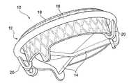
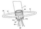
図1Aおよび図1Bは、図面をよく理解するために2つの異なる側面から見たものであって、本発明の実施形態に従い房室弁の機能を置換するために用いられる移植可能な人工器官10の概略図である。 FIGS. 1A and 1B are two different aspects for better understanding of the drawings and are intended to be used to replace the function of an atrioventricular valve according to an embodiment of the present invention. FIG.
図1Aおよび図1Bに図示される人工器官10は、自然弁との境界および支持部を形成する人工器官構造体12と、内部に固定された一連の可撓性人工弁尖14と、によって形成される。人工器官構造体12は単一に形成されるが、その中には機能的に互いに異なり概念的に認識することのできる3つの部分が認められる。実際には中央支持部16と、束縛部18と、前記中央支持部16と前記束縛部18を一体化させる一組の接続部材20と、が認められる。 The
人工器官構造体12は、その各部材と同様に、人工器官の安全性および機能に影響を与えることなく折り畳みできるように設計されている。したがって人工器官の半径方向のサイズを一時的に小さくし、人工心臓を位置決め、移植させる、低侵襲性の手術技術または公知の経カテーテル術と適合させて、人工器官を小口径のアクセスポートから心腔へと導入することができる。言い換えると、経心尖などの直接的な低侵襲性アプローチ、または経腔経由のアプローチから人工器官を心腔内部、移植部位近くに運搬することのできる、径サイズの小さなカテーテルの内部に人工器官10を挿入することが可能であって、人工器官をそこに配置、移植させて、自然弁を機能的に置換している。 The
以下は人工器官構造体をなす様々な部分を説明したものである。中央支持部16は、人工器官の血液流路の導管を定める人工器官構造体の一部分である。中央支持部16の内部には可撓性の人工弁尖が固定されており、これにより導管内の血流が一方向性となる。各人工弁尖14は中央支持部16の内側面と接するシール縁部を有し、また反対側の縁部は自身が人工器官10内部の血流パターンに応じて自由に配置されている。順流の条件下、つまり開放した心弁形状では、人工心弁14は実質的に血流方向に曲がり、自由縁部が中央支持部16の軸から遠ざかり、血流の妨げが最小限となる。一方、閉鎖された心弁形状において、人工弁尖14は血流方向を横断するように位置し、各人工弁尖14の自由縁部が隣接する人工弁尖の自由縁部に接触して、導管の開口部を完全に塞ぐようになっている。このようにして、心弁の主な機能、つまり内部の血流を一方向性にする機能が働いて、逆流が防止され、また順流への干渉が最小限に抑えられる。 The following describes the various parts of the prosthetic structure. The
図1Aおよび図1Bに図示される実施形態において、3つの人工弁尖14があるが、3つは円筒口にある弁尖の最適な数である。しかしながら、弁尖の数が2など、それよりも少ない数だったとしても、或いは3よりも多い数だったとしても、その作動原理が大きく変化することはない。中央支持部16は放射状に折り畳み可能な弾性構造体であって、その弾性回復性により、閉鎖した人工弁尖14の自由縁との接合、つまり接触を保つ最大径を越える径まで拡張する性質がある。 In the embodiment illustrated in FIGS. 1A and 1B, there are three
束縛部18は、中央支持部16の自由な拡張を抑えて制限する人工器官構造体の一部であって、人工弁尖14間の接合を保つことに適合する最大の半径を越えないようにしている。束縛部18は実質的に環状の形状を有し、長手方向に非伸縮性となっており、つまり中央支持部16が内部で拡張し、外側に対し半径方向の力が加わっても、周囲方向の長さを大きく変わらないようになっている。移植術の際、移植部位に合わせて人工器官10の最終的な解放の位置決めがなされると、自然房室弁の外側に束縛部18が配置されて弁尖を完全に取り囲み、同時に中央支持部16が自然弁の弁尖の内側で房室弁口の軸上に実質的に位置する。最終的な開放の後、中央支持部16が拡張して束縛部18に触れ、これが外面に連結する。人工器官構造体の設計によって、自然弁尖は人工器官10の2つの部分の結合部の内部に挟まれたままとなる。さらに束縛部18は自然弁輪を安定化させ、中央支持部16によって及ぼされる半径方向の力を、人工器官の効果的な留置を保証しつつ、周辺の生体構造へ及ぼされないようにする機能を有するが、これは普通、房室弁を機能不全にさせる疾患に関連する変性プロセスおよび拡張プロセスにより影響を受ける。 The
最後に、一連の接続部材20は中央支持部16と束縛部18を物理的に結合させる人工器官構造体12の一部分で、人工器官構造体12を途切れのない一体的なものにしている。この一体的な構造によって人工器官がより安全で効果的になり、人工器官の留置機構が安定的で耐久性のあるものとなり、また以下の図面に説明される具体例から分かるように、迅速で再現性のある人工器官の位置決めによって移植術が単純化、加速化される。 Finally, the series of connecting
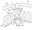
説明の単純化のため、図1Aおよび図1B、ならびにその後の図面において、中央支持部16の外径は束縛部18の内径よりもその寸法が小さく示されている。つまりこれらの図面では、完全に拡張した形状で互いに接触しない人工器官構造体12のこれら2つの部品が示されている。中央支持部16が束縛部18よりも大きい寸法を有することも可能である。この場合には人工器官構造体12の2つの部分の間に干渉があり、束縛部18が拡張抑制作用を発揮すると、人工器官構造体12の2つの部分に挟まれている組織の厚みとは関係なく、実際に中央支持部16が束縛部18に半径方向の力が与えられる。この半径方向の圧力により自然弁の弁尖への留置安定性が向上する。 For simplicity of explanation, the outer diameter of the
図1Aおよび図1Bに説明される本発明の実施形態をさらに説明するため、この具体例として以下に、左心房と左心室の間に位置する心弁である僧帽弁を置換する人工器官を説明する。この目的のために、心臓左側の解剖断面図を図2に示す。ここに、心室の後壁と左心房を取り除くと現れる、心臓左側の長手軸に沿う断面が示されている。これから後弓から突出した僧帽弁が可視可能であって、後尖は前面に、前尖は開口部の反対側に位置している。心弁の平面上の弁尖の挿入ラインに、僧帽弁輪が認められる。後尖と前尖の間を通過する弁輪の領域は交連部位と示されている。選択された解剖断面は、腱索および乳頭筋からなる弁下器官も明確に示している。この弁下器官によって弁尖自由縁と心室壁との連続性が形成される。 To further illustrate the embodiment of the present invention illustrated in FIGS. 1A and 1B, a specific example of this is the following: a prosthesis that replaces the mitral valve, which is a heart valve located between the left atrium and the left ventricle. explain. For this purpose, a cross-sectional view of the left side of the heart is shown in FIG. Here, a section along the longitudinal axis of the left side of the heart, which appears when the posterior wall of the ventricle and the left atrium are removed, is shown. The mitral valve protruding from the posterior bow is now visible, with the posterior leaflet on the front and the anterior leaflet on the opposite side of the opening. A mitral annulus is found in the insertion line of the leaflets on the plane of the heart valve. The area of the annulus that passes between the posterior leaflet and the anterior leaflet is indicated as the commissural site. The selected anatomical section also clearly shows the subvalvular organ consisting of chordae and papillary muscles. This subvalve organ creates continuity between the leaflet free edge and the ventricular wall.
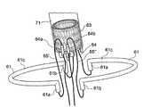
図3は、図1に記載された人工器官10の、本発明の具体的な実施形態による使用例を示す。図3に示された説明図は、僧帽弁内部で拡張し血流の人工器官内の通路を形成する中央支持部16を示す。人工弁尖14はこの通路の内部にあって、血流を一方向性にする働きをする。中央支持部16は自然僧帽弁の内部にあり、一方、人工器官の束縛部18は自然弁尖の裏側に位置し、中央支持部16の拡張に対する制限抑制具として、僧帽弁を外側から取り囲んでいる。移植された人工器官が僧帽弁輪にストレスを一切かけないように人工器官構造体12が設計されている様子が明らかである。人工器官構造体における2揃いの接続部材20は、各自然弁尖の中線に近い弁下スペース内部にて僧帽弁を横切っており、この領域で解放しやすい腱索の束との干渉が防止される。具体的な解剖図によれば、図3は接続アーム20のグループの一方、つまり後尖を横切るもののみが示されている。同様の配置は前尖の中央部にも対称的に形成されており、図3では隠れたままになっている。各弁尖の中央部において、図2の後尖に示されているように、自由縁から突出した腱索の束に解剖学的な孔が有効的に形成されている点に注目されたい。各弁尖は実際、腱索によって両乳頭筋へと接続され、これは心室のほぼ反対側の場所に認められる。腱索の櫛状部にあるこの孔は、人工器官構造体の接続部材20の良好な通路を構成する。 FIG. 3 shows an example of the use of the
図3からは、臨界収縮期の全期に渡って、房室弁が閉鎖すると、心室内圧が最大値を取るときに、心室内圧によって人工器官が心房へと推進し、接続部材20が人工器官の留置に役立つ様子も明らかである。また自然弁尖の裏側で分離している束縛部18と共に、接続部材20が中央支持部16を弁輪に確実に固定する一構造体として機能し、人工器官構造体の内部に自然弁尖を捕捉し挟み込むことによる留置動作が効果的に組み込まれている様子が明らかである。 From FIG. 3, when the atrioventricular valve is closed over the entire period of the critical systole, when the intraventricular pressure takes the maximum value, the prosthetic device is pushed to the atrium by the intraventricular pressure, and the connecting
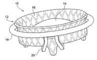
図4は本発明の別の実施形態による人工器官構造体22の別の型を示す。この実施形態において人工器官構造体の束縛部24は環状の非伸縮性形状を保つが、一軸に引き伸ばされた楕円形状をしており、図1で図示される略円形の束縛部18の代替選択肢となっている。図を簡単にするために弁尖は図示せず、これは説明の目的には不要であって、さらに圧縮された形状にて中央支持部16が示されており、これは最終解放前の移植術の最中に想定される形状の一例として示されている。 FIG. 4 illustrates another type of
図4に示された形状を参照して、接続部材20に腕部が設けられることがいかに適当であるか注目すべきであり、これは比較的厚い断面(説明のため0.25mmから0.75mmの範囲内とするがこれに限られない)、と非常に大きな横断寸法(例えば0.5mから3mmまでの範囲とするが、これには限られない)を有している。このような寸法決め、特にループを用いた設計により、接続部材20は半径方向に可撓性を有するが、接線方向、つまり軸方向へ加重がかかった場合に剛性を有する。したがって、図4に図示されるように、これらは中央支持部16が未だ圧縮された形状にありながら束縛部が配置されるような場合に、束縛部24(若しくは18)と中央支持部16との間に形成された半径方向の距離の変化を補うのに適している。同時に、これらは移植術の最中にこれら2つの部材の間の基準を明確に保つことに適しており、例えば、僧帽弁輪に接して人工器官を位置決めする際、中央部材に対し束縛部品が外れるのを防止する。 With reference to the shape shown in FIG. 4, it should be noted how appropriate it is for the connecting
伸長、楕円、または豆型の、対称または非対称の形状を有する束縛部24は、疾患が存在していたとしても、自身を大動脈弁輪の生体形状に連結させる上でより好適な場合が多い。また、移植術の第一段階では、心室腔に既に配置された人工器官の束縛部24は、自然弁輪の心室側面と実質的に適合するものでなければならない。また、束縛部24を弁輪における弁尖の挿入ラインに近接して配置することにより、最も厚くて頑丈な弁尖部位において留置の寿命が確実となり、同時に、心弁の全周縁に沿って弁尖の連続性が存在することで、逆流に対する完全な緊密性が確実となる。最後の点に関して言えば、弁尖の長さは交連部位で大きく減少しており、ここにて心弁の2つの弁尖の移行がある点を考慮しなければならない。したがって、心室で人工器官が低すぎる場所に配置されると、これによって束縛部と中央部材の連結部に挟まれた弁尖の連続性が、交連領域の位置で阻害されるリスクが高まり、自身が主弓部までに制限される。 An elongated, elliptical, or bean-shaped, symmetric or
密閉リングの連続性が欠如すると人工器官導管の外部に漏れ口が形成され、逆流に対する人工器官の緊密性が失われる。人工器官の弁輪部の形状を、治療する疾患と生体構造に応じて選択することによって、当該構造体自身を自然弁輪に近い、自然弁尖の裏側へと、より簡単に、またより効果的に位置決めさせることができ、各部位に応じた形状によって位置決めが促進される。最新技術で知られている簡単な病態生理的な考察に基づいて、弁輪部位に最も適する形状を、スペースの鞍状形状などに応じて、二次元と三次元の両方から選択することができる。 The lack of continuity of the sealing ring creates a leak outside the prosthetic conduit and loses the prosthetic tightness to backflow. By selecting the shape of the annulus of the prosthesis according to the disease to be treated and the anatomy, it is easier and more effective to move the structure itself to the back of the natural leaflet, close to the natural annulus. Positioning is facilitated, and positioning is facilitated by a shape corresponding to each part. Based on simple pathophysiological considerations known in the state of the art, the most suitable shape for the annulus area can be selected from both 2D and 3D depending on the saddle shape of the space, etc. .
自然弁輪と結合する初期段階で環状部に採用される形状、特に人工弁尖の最適な作動条件を保証する人工器官の開口部の形状は、拡張された人工器官構造体の最終形状に必ずしも影響しない点に注意されたい。もちろん、本発明の種々の実施形態に応じ、相当の自由度をもって束縛部の湾曲に対する剛性を変化させ、また異方性弾性を有する断面を形成しつつ、該当部分を長手方向の非伸縮性の必須要件に合致させることも可能である。環状部は、その部材自身によって定められる平面上に留まるような変形に対して十分な可撓性があり、一方この平面から逸脱する直接的な変形に対して十分な剛性を有するように設計することができる。このような設計により、器具を最適な移植部部分に位置決めする際、束縛部が人工器官の軸方向に変形しなくなり、中央支持部の外面における連結域に対し誤って配置されることが防止される。同時に、平面上での変形により、自身が中央支持部の拡張形状に完全に適合することができ、さらには、人工弁尖を有する支持部材に予め定めされた作動形状が必要とされる人工弁尖の正常な動作が妨げられることなく、2つの構造体の間に途切れることのない結合が促進される。上記の例として、束縛部は自然弁輪に連結させるのに適当な楕円形状に設計することが可能で、同時に自然弁の弁輪下の環状溝に配置させるとき、当該平面の外側での変形に対して剛性を有することにより、前記束縛部を位置決め段階の間ずっと平坦に保つことが可能で、また最終的な移植時に、その平面における変形性によって支持部材の最終円筒形状に適合するようになっている。 The shape adopted for the annulus at the initial stage of coupling with the natural annulus, especially the shape of the prosthetic opening that guarantees the optimal operating conditions of the prosthetic leaflets, is not necessarily the final shape of the expanded prosthetic structure. Note that there is no effect. Of course, according to various embodiments of the present invention, the rigidity of the restraint portion with respect to the curvature is changed with a considerable degree of freedom, and the corresponding portion is made non-stretchable in the longitudinal direction while forming a cross section having anisotropic elasticity. It is also possible to meet essential requirements. The annulus is designed to be flexible enough to deform in such a way that it stays on a plane defined by the member itself, while being sufficiently rigid against direct deformation deviating from this plane. be able to. Such a design prevents the restraint from being deformed in the axial direction of the prosthesis when positioning the instrument in the optimal implant part and is prevented from being misplaced relative to the connection area on the outer surface of the central support. The At the same time, due to the deformation on the plane, the valve itself can be completely adapted to the expanded shape of the central support part, and further, a prosthetic valve that requires a predetermined operating shape for the support member having the prosthetic valve leaflet The uninterrupted coupling between the two structures is facilitated without disturbing the normal operation of the apex. As an example of the above, the constraining portion can be designed to have an elliptical shape suitable for being connected to the natural annulus, and at the same time, when being arranged in the annular groove under the annulus of the natural valve, So that the restraint can be kept flat during the positioning phase and adapted to the final cylindrical shape of the support member due to its deformability in its plane during final implantation. It has become.
単に例示の目的のため、本発明の一般的性質を制限することなく、上記の異方性弾性応答性の性質を持つ束縛部26が人工器官構造体に一体化された実施形態が図5Aに示されており、また、より明確にするため、図5Bでは分離した形で図示されている。束縛部26は略管状に形成され、その可撓性は選ばれた寸法および位置を有する一連の開口部28によって調節される。図5Aおよび図5Bに示された例において、開口部28は、2つの主ジェネレーターに沿って配列しており、一方は束縛部26の内面に、他方は外面に設けられる。これにより上側と下側に1つずつ、2つの連続バンド30a,30bが形成され、これにより平面外側の変形に対して環状部が剛性化する。このような剛性はバンドの幅に応じたものである。個々の開口部の寸法および隣接する開口部との距離は、一方で、平面内の可撓性に対する弾性的な性質を定めている。 For purposes of illustration only, without limiting the general nature of the invention, an embodiment in which the restraining
束縛部32の実施形態の別の例が図6に記載されている。また、より明確にするため、この図面では束縛部32が残りの人工器官構造体から分離した形で図示されている。この例において、本発明の一般的性質を制限することなく、束縛部32は環状部の異性弾性応答を小さくする周期的な順番に配置された開口部34を有する管状であって、これにより表面により一層、一様に分布した開口部となる。この形状においてもまた、屈曲方向に応じて弾性応答を調節することが可能である。例えば、束縛部32の内外側に位置する開口部34と比べて、上下側に位置する開口部34のサイズを小さくすることによって、該構造体と同一平面上の変形と比べて、当該平面外での変形に対し大きな剛性が得られる。また、例示の目的のため、本発明の一般的性質を制限することなく、図6は弁輪部の角度位置によって開口部34のサイズを調節し、所定の要件に応じて円周に沿って変化する弾性的性質を有する構造を得ることができるようになっている。図6に図示された形状によれば、例えば、束縛部32の屈折可撓性は各断面で異方性を有するままとなるが、その屈折可撓性は接続部材20のある連続部分から中間領域を最大とし、その距離が置かれるごとに屈折可撓性が増してゆく。 Another example of an embodiment of the binding
図5および図6に図示された実施形態は、束縛部の構成部品を概念的に表したものである。移植部位における生体構造への外傷リスクを減らすため、このような構成部品をシリコーン或いはポリウレタンなどのポリマー材、および/または組織で覆い、連続する無傷の外部表面を再構築することができる。束縛部品の外面に、人工および生物由来の両方の組織を使用することによって、内皮化の適正が高められ、これにより移植部位で生理学的に一体化する。 The embodiment illustrated in FIGS. 5 and 6 conceptually represents the components of the binding portion. In order to reduce the risk of trauma to the anatomy at the implantation site, such components can be covered with a polymeric material, such as silicone or polyurethane, and / or tissue to reconstruct a continuous intact external surface. By using both artificial and biological tissue on the outer surface of the constrained component, the suitability of endothelialization is increased, thereby physiologically integrating at the site of implantation.
上述の通り、房室弁の弁下構造は心弁と心室壁との間に生体的で機能的な連続性を形成している。各弁尖はこのように、一方が弁輪を介し、他方が腱索と乳頭筋を介して、心臓構造と連続するようになっている。このような連続性は心室腔の安定に重要であり、あらゆる干渉を回避することは心弁不全の治療に望ましい。この束縛により、人工器官構造体の束縛部で房室弁を外から取り囲むという要件を満たすことができ、これは一時的な開放形状を設け、自然弁尖の裏側と心室壁との間にできたスペースに、心室と心弁の連続性を妨げることなく配置させることによって達成することができる。束縛部が屈折可撓性と長手方向の非伸縮性を有するという二次的な要件は、開放形状が自然弁の裏側の移植前の位置に対応する一時的な状態を表しており、一方、実際の移植時の作動条件の下では、束縛部は閉鎖した実質的に連続する形状を有するということを意味する。 As described above, the subventricular structure of the atrioventricular valve forms biological and functional continuity between the heart valve and the ventricular wall. Each leaflet is thus continuous with the heart structure, one through the annulus and the other through the chords and papillary muscles. Such continuity is important for ventricular cavity stability, and avoiding any interference is desirable for the treatment of heart valve failure. This constraint can meet the requirement of surrounding the atrioventricular valve from the outside with the constrained portion of the prosthetic structure, providing a temporary open shape between the back of the natural leaflet and the ventricular wall. This can be achieved by placing it in an open space without disturbing the continuity of the ventricle and the heart valve. The secondary requirement that the restraint has refractive flexibility and longitudinal non-stretchability represents a temporary state where the open shape corresponds to the pre-implantation position on the back of the natural valve, Under actual implantation operating conditions, this means that the restraint has a closed, substantially continuous shape.
図7は本発明の様々な実施例による人工器官構造体の一例を示し、一時的な開放形状から閉鎖形状に移行する形状を有する束縛部36を表す。図に示された例において、本発明の一般的性質を制限するわけではないが、束縛部36は2つの湾曲した区分37,38に分離し、各区分37,38は自然弁の弁尖裏側に位置決めされたその後の段階で、環状形状を再閉鎖させる機構を有する。図示された例において、この機構は空洞40に面した鋸歯等の形状ピン39を備え、一度形状ピン39が空洞40へと挿入されると、当該空洞は形状ピン39が抜けないような設計および寸法を有する。空洞40は、半径方向に弾性を有するように設計することができる。このようにして形状ピン39と空洞40に軽度の干渉を持たせ、これにより閉鎖機構の確実性と信頼性が高まる。言うまでもなく、閉鎖機構は同等の代替形状をとることができる。例えば、空洞40の内部は鋸歯形状を有し、空洞40内部に突出した弾性ラメラ(図示せず)によって生成される。一般的に、人工器官構造体の形成に超弾性素材を使用することにより、結合の有効性を改善させる変形可能な構造体が形成されやすくなる。 FIG. 7 shows an example of a prosthetic structure according to various embodiments of the present invention, representing a
図8Aおよび図8Bは人工器官構造体の別形態を示し、これもまた本発明の様々な実施形態に則したものである。図8Aに記載された解決手段は、僧帽弁への移植に特に有利となる形状を有する。この形態では、後尖のある後後円輪弓37´が前尖のある前円輪弓38´よりも長くなるように、束縛部36が非対称的に分割にされ、自然弁の生体構造などが再現されている。この場合、後尖の裏側に一度挿入されると、より長い区分が交連領域を取り囲み、この区分の両端には適当な湾曲部が形成されて、LVOT(左室流出路)として知られている、心室の大動脈下スペースに、両側の閉鎖機構が配置される。心室のこの領域は、僧帽弁下器官の構成要素を実質的に含まないが、束縛部の再閉鎖機構は、開胸手術の場合には直接的に、経カテーテル術の最中に介入技術を用いて発動させた方がよりシンプルである。図8Aはまた、図8Bで詳細に閉鎖機構の別設計を示している。この設計において、区分の両端には軸方向に突出した成形部41が設けられている。図8Bの例において、本発明の一般的な性質を制限するわけではないが、この成形部41は球体42の形状を有し、球体42よりも径の小さなピン43によって区分の端部が接続されている。その他の区分における対応端部の側面には盲空洞44が設けられ、これは前述の形状を窪んだ形で再現しており、これは成形部41を受け入れてロックすることに好適である。この盲空洞44が区分の外面に位置することは、中央支持部16から束縛部36に及ぼされる半径方向の力が、その拡張後に、接続の安定性に寄与し、これが受け入れられる空洞から成形部41が脱落することが防止されることを意味する。 8A and 8B show another form of prosthetic structure, which is also consistent with various embodiments of the present invention. The solution described in FIG. 8A has a shape that is particularly advantageous for implantation into a mitral valve. In this embodiment, the constraining
束縛部の各区分が可撓性を有することにより、自然弁尖の裏側での位置決めが促進される点に注意されたい。また束縛部の各区分の間に存在する孔を、単なる例示のため、図7および図8に記載のものよりも大きく広げ、これにより自然弁を各区分全部で取り囲むことも可能である。 Note that the flexibility of each section of the restraint facilitates positioning on the back side of the natural leaflet. It is also possible for the holes present between the sections of the constraining portion to be larger than those shown in FIGS. 7 and 8 for illustrative purposes only, thereby enclosing the natural valve in all sections.
図9Aおよび図9Bには、これは本発明の実施形態において、房室弁の機能を置換するために開発された移植可能な人工器官の別実施形態が記載されている。この実施形態において、束縛部50は前述の二次元或いは三次元、何れの形状を有することも可能だが、2以上の区分または分割要素51に分割されており、これらは互いに分離しており、束縛部を接続部材20に合わせて切断させることによって得られる。さらに各分割要素は、可逆的なロック機構の実施形態を用いてこれら接続部材から一時的に分離可能であるが、最終的な移植形状では接続部材に係合させることができる。 9A and 9B describe another embodiment of an implantable prosthesis developed to replace the function of an atrioventricular valve in an embodiment of the present invention. In this embodiment, the constraining
束縛部を2以上の分割要素へと分割させることと、前記2以上の分割要素を中央支持構造体の接続部材から解放可能であることを組み合わせることにより、移植術の第一段階で、自然弁尖の裏側に束縛部を迅速に位置決めさせることが可能となる。その後、人工器官構造体の一体性を復元し、すべての機能性を回復させることにより、最終的に移植が可能となる。束縛部の構造連続性により、長手方向の非伸縮性と中央部本体の径方向の拡張を抑え制限することも確実にできるようになり、したがって束縛部の構造連続性は人工器官構造体に存在する接続部材が貢献して得ることも可能である。 By combining the constraining portion into two or more split elements and the two or more split elements being releasable from the connecting member of the central support structure, the natural valve can It is possible to quickly position the binding portion on the back side of the apex. Thereafter, the integrity of the prosthetic structure is restored and all functionality is restored, so that transplantation is finally possible. The structural continuity of the constrained part also ensures that the non-stretchability in the longitudinal direction and the radial expansion of the central body can be suppressed and constrained, so the structural continuity of the constrained part is present in the prosthetic structure It is also possible for the connecting member to contribute.
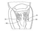
純粋な説明のため、本発明の一般的性質の制限することなく、上記実施形態による移植可能な人工器官の一実施例を図10A〜図10Cに詳細に説明した。 For purely illustrative purposes, an example of an implantable prosthesis according to the above embodiment is described in detail in FIGS. 10A-10C without limiting the general nature of the present invention.
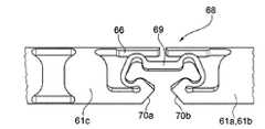
図10Aには表示の簡単のため略円形状の束縛部50が図示されているが、2つの分割要素51に分割され、必ずしも対称とは限られない束縛部50の連続性は中央支持部16に対し接続部材20に一致して途切れている。各分割要素51の各端部52には、好ましくは環状平面の外側に向くピン53が設けられている。図10Aはこのピンが環状平面と略垂直方向を向く実施形態を示している。一方、接続部材20にはこれらピンを各々受け入れるのに適した筒状空洞55が設けられている。2揃いの接続部材22の各々に1組の筒状台座55が存在しており、中央支持部16に正対する角度位置に略配置している。これら筒状空洞55には、ピン-空洞の結合部の摩擦力を増加させるのに、束縛部50の各区分の端部にあるピン53と同様に、ラメラ、歯部、またはその他の非連続面を設けることが可能で、束縛部50の分割要素51と接続部材20の結合安定性を改善させることができる。筒状台座55は、束縛部50の分割要素51にあるピン53が向く方向と同じ方向に向けられており、ピン-空洞の結合部によって、この部分が自然弁輪と形状的に整合性のある平面に保たれるようになっている。 Although FIG. 10A shows a substantially circular
図10Bには、自然弁の裏側に一度位置決めされると、束縛部50の分割要素51が人工器官構造体の中央部材16へと戻り、各ピン53が、2つの部分に挟まれる接続部材20にある筒状空洞55と、実質的に並列する様子が示されている。 In FIG. 10B, once positioned on the back side of the natural valve, the
図10Cは、接続部材20に形成されるピン-空洞の結合部を介し人工器官構造体の中央部材16に再連結される、束縛部50の各区分51を示している。図10に図示された実施例から、人工器官構造体の一体性を再構築するプロセスの最後において、束縛部50は人工器官の全周にわたって途切れることがなく、また短横構造体56の存在によって長手方向に非伸縮となる様子を認めることが可能で、短横構造体56は接続部材20に一体化された部材であって、各組の筒状空洞55の各組を一体化させている。図10Cに示されるように、人工器官構造体の一体性が再構築された後にはじめて、人工心弁の位置決めおよび移植へと進むことができるようになる。もとの形状においてのみ、実際、自然弁に対する人工器官の正常な位置決め、つまり束縛部50と中央支持部16の相対的に最適な位置決めを同時に実行することが可能であって、逆流に対する人工器官の完全な緊密性、移植部位への人工器官の効果的な留置、ならびに前述の通り、接続部材による安定性が確実となる。 FIG. 10C shows each
ピン-空洞の結合機構は、図10A〜図10Cに記載の通り、純粋な説明のために示され、本発明の一般的な性質を制限する意図ではない。束縛部品の各区分と接続部材の可逆的な連結部を形成する種々の解決手段は、従来技術で公知であり、ここに記載される発明の実施形態にて使用可能である。 The pin-cavity coupling mechanism is shown for pure illustration as described in FIGS. 10A-10C and is not intended to limit the general nature of the invention. Various solutions for forming a reversible connection between each section of the constraining part and the connecting member are known in the prior art and can be used in the embodiments of the invention described herein.
図11A〜図11Gは、純粋な例示によって、図10に記載の移植可能な人工器官の実施形態の移植手順を図示している。図11に図示されている手順は自然弁を除去することなく僧帽弁を置換するための低侵襲性の外科手術を想定している。移植部位へのアクセスは、外科手術に伴う通常の慣習に従って、左心房から僧帽弁まで順行性アプローチを用いる。左心室が空である場合が想定されており、最新の内視鏡技術を用いて、或いは直接的にアクセス可能であるが、心臓を停止させる必要はない。治療の方針および技術は、心尖などの逆行性アクセスを用いても、十分有効で使用可能であり、また心臓を開胸せずまた体外循環器を全く用いない処置をすることができる介入技術に基づく経カテーテル型の手順を用いても、十分に有効で、かつ使用できる。 11A-11G illustrate, by pure illustration, the implantation procedure of the implantable prosthesis embodiment described in FIG. The procedure illustrated in FIG. 11 assumes a minimally invasive surgical procedure to replace the mitral valve without removing the natural valve. Access to the implantation site uses an antegrade approach from the left atrium to the mitral valve in accordance with normal practice associated with surgery. It is envisaged that the left ventricle is empty and can be accessed using the latest endoscopic techniques or directly, but it is not necessary to stop the heart. The treatment policy and technique is an intervention technique that is sufficiently effective and usable even with retrograde access such as the apex of the heart, and that can perform treatments that do not open the heart and do not use any extracorporeal cardiovascular system. Even a based transcatheter-type procedure is sufficiently effective and usable.
移植術の説明のため、図2で既に説明した心臓左側の生体モデルと同じ生体モデルが用いられる。 For the description of the transplantation, the same biological model as the biological model on the left side of the heart already described in FIG. 2 is used.
図11Aは移植術の第1ステップを示し、これは心室内部に、人工器官構造体の束縛部50の分割要素51を形成する2つの半アーチ状区分の位置決めからなる。ここに採用する移植術についてすでに説明したように、分割要素51は僧帽弁から左心室へと、外科的アプローチに適合する直接的な操作を用いて導入される。これらは各々、僧帽弁の交連域の裏側に位置し、心弁の半分に対応して関わる腱索の束をすべて受け入れるようになっている。分割要素51の向きは接続ピン53が心室の心尖、つまり操作者に対し遠位に向くようになっている。外科的なアクセスにより、場合によっては内視鏡装置の補助を受けて、移植部位、とりわけ左心室内部を直接視することが可能になる。これによって2つの分割要素51の位置、例えば、僧帽弁の弁下器官全体の外側に配置することを、次の段階へと進む前に、正確に確かめることができる。 FIG. 11A shows the first step of the implantation, which consists of positioning of two semi-arched sections forming the
図11Bは、人工器官構造体の残りの部分を、中央支持部16を径方向に小さく折り畳み且つ解放システムの包含シースを用いて、残りの部分をこの形状を維持しながら、心室へと導入することを示している。接続部材20は解放システムのシース外側にフリーな状態とすることができるが、心室への導入操作の最中は、シース内側に圧縮して、外傷を付けない導入形状および小さな形状を有するようにし、心室内部に入ると選択的に解放することもまた可能である。説明の簡単のため、図11Bには束縛部の分割要素51から一定の距離が置かれて、フリーになった接続部材20を示している。 FIG. 11B introduces the remaining portion of the prosthetic structure into the ventricle while folding the
図11Cは、束縛部50の第1分割要素51が、両端部に予め配置されたピン-空洞結合部を用いて、接続部材51から中央支持部16へ再連結する様子を示している。この操作は開胸手術の最中に直接または内視鏡で視認しながら簡単に遂行することが可能だが、開胸しない経カテーテル術を用いる場合には介入技術を必要とする。 FIG. 11C shows a state in which the
図11Dは、束縛部のもう一つの分割要素51に対して行われる同様の操作を示している。人工器官構造体の一体性がすべてこのように再構築され、人工器官を移植する準備ができる。弁下器官を含む僧帽弁は、最小径サイズに畳まれたままの形状となる中央支持部16と、心弁外側の心室内に完全に全部配置された環状の束縛部50と、の間に完全に収まっている。人工器官構造体の上記部品は、本発明の原理および図1に説明される実施形態に従って、接続部材20を介し連結され、これらの間に一体化される。 FIG. 11D shows a similar operation performed on the
図11Eおよび図11Fには、人工器官構造体の一体性が再構築され、また解放システムを介し移植者によって得られる中央支持部16の再配置により、束縛部材50に無傷の再配置が伴う様子が示されている。解放システムはこのようにして、正常な移植部位に到達するよう、近接方向に移動する。正常な移植配置とは、束縛部50がいわゆる弁輪下溝に割り当てられる僧帽弁輪の心室側面に接すると同時に、人工器官の中央部材16が、折りたたまれた形状のまま、自然弁に広がっているときを指す。図11Fに説明される最終移植の直前形状により、図1に概念的に記載される人工器官が、本発明の種々の実施形態とは独立に、操作者に特別な技術を要求することなく最適な位置決めを行うことができる様子が理解できよう。実際、束縛部50と中央支持部16の間に存在する構造一体性によって、自然弁輪の仮想面に対して、人工器官が遠すぎる位置(心室の奥深く)に配置されること、または近すぎる位置(心房方向に大きく変位した位置)に配置されることが防止される。実際には移植する者が解放システムに対して近位方向に僅かな力を加えれば十分であって、これにより、束縛部材50が弁輪に正確に接触し、正常な解放位置が確実に達成される。束縛部50が心房に入り込めず、同じ自然僧帽弁輪の心室側で隔離されていることによって、実際、解放システムに張力が生じ、人工器官の位置が基端部に寄り過ぎることが防止される。 In FIGS. 11E and 11F, the integrity of the prosthetic structure is reconstructed and the repositioning of the
図11Gは移植術の最終段階において、中央支持部16が解放し、束縛部50に達するまで拡張し、束縛部50に接触する様子を示している。自然僧帽弁の弁尖は人工器官構造体の2つの部材に挟まれ、人工器官の安定した留置を確実にし、血流の逆流に対して有効な緊密性を提供する。 FIG. 11G shows how the
経カテーテル介入術の使用に完全に適合する移植可能な人工器官に関する別の実施形態が図12A〜図12Eに図示されている。 Another embodiment for an implantable prosthesis that is fully compatible with the use of transcatheter intervention is illustrated in FIGS. 12A-12E.
図12Aおよび図12Bは、上記記載を詳しく理解するための2つの異なった視点によるものであるが、経カテーテル術を用いて房室弁に移植するために特に有利な実施形態における人工弁器官を示す。この場合にも、前回の実施形態と同様に、束縛部60は、これを2以上の区分または別々の分割要素61に分割可能であるから、健康な房室弁または疾患のある房室弁の生体構造に応じて、その全体に二次元または三次元的な形状を有することができる。各分割要素61は可逆的なロック機構を用いて、その接続部材64から一時的に分離することができ、また一方で、移植の最終段階で接続部材64に連結される。 FIGS. 12A and 12B are from two different viewpoints for a better understanding of the above description, but the prosthetic valve organ in a particularly advantageous embodiment for implantation into an atrioventricular valve using transcatheterization. Show. In this case as well, as in the previous embodiment, the constraining
図12Cは中央部63から分離した束縛部60を構成する分割要素61を示し、人工器官の一部に存在する可逆的なロック機構62の構造がより見えやすくなっている。 FIG. 12C shows the dividing
図12Dおよび図12Eはロック機構62の拡大図を図示している。 12D and 12E show enlarged views of the
ここに記載される解決策において、本発明の一般的な性質を制限することなく、接続部材64は中央部63に一体化し、その周囲にて外部に突出しているが、各々に、一組の中空ピン64a,64bが設けられ、これらは平行で、十分な間隔を介しており、人工器官自身の軸に対して実質的に並列となる。接続部材64の数は分割要素61の数に等しく、人工器官の束縛部60は分割され、束縛部60自身に途切れがなく、接続部材64を用いて再構築されるようになっている。図12Dに示されているように、同分割要素61の各ピン64a,64bは中空状であるために、以下にこれを明確に説明するが、ガイドワイヤが内部に自由に通過できるようになっている。同様に、束縛部60の各分割要素61の端部61a,61bは、これに制限されるわけではないが好ましくは、略円筒状の中空構造体からなり、図12Eに示されるように、ガイドワイヤを自由通過させることに好適なだけでなく、接続部材64にある対応ピン64a,64bと安定して接続できるような寸法を有している。束縛部64の各分割要素61の中空状の端部61a,61bは分割要素自身の主平面に対して略垂直な方向を向いている。このようにして、人工弁器官の構造的な一体性が再構成されると、束縛部60は、全体的に自然弁の環状平面に対して平行となる。 In the solution described here, without limiting the general nature of the present invention, the connecting
束縛部60の各分割要素61の端部61a,61bにある筒状空洞と、接続部材64にあるピン64a,64bの両方にはピン-空洞の結合部の摩擦力を増加させるのに、ラメラ若しくは歯部、その他の非連続面を設けることが可能で、これにより相互結合の安定性を改善させることができる。 Both the cylindrical cavity at the
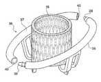
最後、束縛部60の各分割要素61の全構造には、その全部または少なくとも大部分の長さに沿うガイドワイヤ65´,65´´用の通路を設けることができる。このようにして分割要素61は、心室内部の自然弁弁尖の裏側に配置させやすくなる。実際には、ガイドワイヤ65´,65´´を、臨床で現在使用されている公知介入技術を用いて、分割要素61の望ましい位置決めが認められる経路に沿って配置させ、前記分割要素がガイドワイヤ65´,65´´自身に沿って導入されれば十分である。 Finally, the entire structure of each
図13A〜図13Eは束縛部60が分割され、経カテーテル術を用いて施される移植術に特に適した、分割要素61の実施形態の一例である。 13A-13E is an example of an embodiment of a
図13Aは、表示の簡単のため、人工器官の束縛部60から構成される分割要素の構造部分のみを示している。上記のように、この構造体は管状部材66から実質的に得られるものであり、その壁面には開口部67が形成され、これらは所望の弾性特性を有する構造を提供するために好適にはサイズと位置決めがなされ、また弾性特性は異方性のものとすることが可能で、分割要素61の経路に沿う位置に応じて区分毎に変化することができる。その後分割要素61の構造は図13Aに概略的に示すように形成され、つまり、中央部61Cは束縛部60として選ばれた形状に適合するように湾曲し、一方でその端部61a,61bは分割要素61の中央部61cに対して実質的に直角に屈曲している。分割要素61の最終形状、例えば図13Aで示される形状は、型内部に保持される部品に適当な熱処理を加えることにより、最終生成段階で決めることができる。 FIG. 13A shows only the structural portion of the dividing element composed of the
図13Aにおいて、好適には筒状の2つの端部61a,61bが明確に認められ、これらは中央部61Cの構造主平面に対して直角に屈曲している。これら端部61a,61bには、人工器官の中央部63への接続機構の一部を形成する、分割要素61の部材が備えられる。これら端部61a,61bは、移行領域68を介して分割要素61の構造における中央部61cへと接続し、移行領域68は一方向性の結合部として機能し、分割要素の残りの平面と同じ面に当該端部が一方向性に再配列するが、反対の方向には配列しないようになっており、分割要素61が一度、人工器官の中央部63に接続されると、分割要素61の主平面と人工器官の軸が互いに90°より大きく曲がらないようになっている。この機能的な要件によって束縛部60の分割要素61が心室腔の内部に折れ曲がるリスクが回避される。このようにして、自然弁輪に対する束縛部の接触連続性と束縛部60と中央部63の正確な相互配置の両方が、人工器官の最終解放と同時に保証される。 In FIG. 13A, two
図13Bおよび図13Cは例示によって、発明の一般的な本質がこれにより制限されることなく、上記の一方向性結合部68の実施形態を図示している。ここにおいて、分割要素61の端部61a,61bは一組のコイル69により構造体61cの残部へと接続され、前記コイル69は管状体66の壁面に直接形成され、角状のバネとして機能するように形成される。この解決手段は、上記分割要素61の加工プロセスに適合する。 13B and 13C illustrate the embodiment of the
より詳細に、図13Bは折り曲げられた、つまり作動状態にある結合部68の形状を示している。角度末端停止部を形成するため、結合部68に隣接した管状体66の2区分の下面70a,70bは角度をつけて切られており、90度まで湾曲すると互いに接触し、同時に弾性コイル69がまとまりを持って閉鎖するようになっている。これら2つの側面が合わさると端部61a,61bが分割要素61の構造の中央部61Cに対してこれ以上屈曲しないようになる。図13Cは、直線化された結合部68の形状を示している。これまで接触していた2区分70a,70bの表面が離れ、連結弾性コイル69は開放されている。弾性コイル69の形状は、その変形が実質的に一様に分散され、材質に応力が集中しないようになっている。 More particularly, FIG. 13B shows the shape of the
図13Dおよび図13Eは、構造体66の網状構造と端部61a,61b近傍に導入された弾性結合部68の構造の複合効果によって、分割要素61が、実質的な直線形状、特に経カテーテル技術を用いた移植に適した形状を想定できるようになる様子を示している。特に図13Dには弾性結合部68によって、端部61a,61bの直線化が可能となる様子が示され、この一実施形態が図13Bおよび図13Cに図示されている。特に図13Eには分割要素61の中央部61Cの網状構造によって、分割要素61の直線化が可能となる様子が示されている。 13D and 13E show that the dividing
当業者であれば、図13に説明されている発明の他の実施例によって、設計の異なる弾性コイル69や、金属材料またはポリマー材料によって構成される追加部品の形態をとる弾性連結部によって互いに連結され、分離した部品として形成された中央部61cおよび端部61a,61bの構造を有する解決手段を提供することができることは明らかであろう。 Those skilled in the art will be able to connect to each other by means of another embodiment of the invention illustrated in FIG. 13 by means of an
単に説明のため、本発明の一般的性質を何ら制限することなく、図14A〜図14Eは図12に説明された移植可能な人工器官の実施形態で可能な経カテーテル移植術を図示しており、完全な経カテーテル介入術に適合した方法で束縛部60を人工器官63の中央部に結合させることを含んでいる。図面をより明確にするため、一連の図面において自然房室弁の表示は省略されている。さらに、2区分の分割要素61に分割された束縛部60を含む人工器官が示されている。明らかに、束縛部がより多くの分割要素に分割された場合にも全く同じ処置を行うことができる。 For purposes of illustration only, without limiting the general nature of the present invention, FIGS. 14A-14E illustrate transcatheter implantation that is possible with the implantable prosthesis embodiment described in FIG. Including coupling the
図14Aは外径の小さなカテーテル70を用いて人工器官の束縛部60における分割要素61を自然房室弁の弁尖裏側に位置決めさせる様子を概略的に示している。この処置の良好な結果を促進・保証するために、各分割要素61に対してそれぞれガイドワイヤ65´,65´´が用いられ、これは分割要素61自体に必要とされる最終位置に一致させて事前に配置される。心室内部にガイドワイヤを案内する方法は、実際には最先端の心臓介入術における公知技術である。図13Eに図示されるように、事前に直線化され、外径の小さなカテーテル70内部に取り付けられる各分割要素61は、このようにして各ガイドワイヤ65´,65´´により案内され、その後、最終の所望位置へと到達する。このような処置は分割要素61の構造体66内部ワイヤ用の通路の存在により可能となる。 FIG. 14A schematically shows a state in which the dividing
図14Bは、分割要素61が一旦移植する最適位置に達すると、運搬に用いられたカテーテル70が除去されるが、分割要素61の構造体66の中にガイドワイヤ65´,65´´を取り残し、両端に操作者がアクセス可能とする様子を示している。カテーテルシース70から解放されると分割要素61は元来の形状を取戻し、これは中央部61cに湾曲部を有し、端部61a,61bが中央部61cの平面に対して屈曲する形状である。 FIG. 14B shows that once the dividing
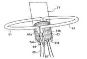
図14Cは人工器官の中央部63が小径に折り畳まれ、この形状にて解放システム71の内部に維持されており、接続機構64の各分割要素61にある各ピン64a,64b内部に存在するワイヤ用の通路にガイドワイヤ65´,65´´の自由端が挿入されていることを示している。このようにして、各ガイドワイヤ65´,65´´は、各組のピン64a,64bを束縛部60の対応分割要素61における2つの端部61a,61bに接続し、ピン64a,64bは人工器官の中央体63と一体化しており、分離して隣接する2つの接続部材64に接して位置する。 In FIG. 14C, the
図14Dは人工器官の中央部63が、解放システム71内部に畳まれた形状のまま、心腔の内部に導入されて、移植位置へ達する様子を示している。 FIG. 14D shows how the prosthetic
図14Eはガイドワイヤ65´,65´´を緊張させて束縛部60の分割要素61における端部61a,61bを互いに接近させ、これを接続部材64と一体化している対応ピン64a,64bに対して整列させる様子を示している。 FIG. 14E tensions the
図14Fはガイドワイヤ65´,65´´をさらに緊張させて、束縛部60の分割要素61における端部61a,61bと接続部材64に一体化したピン64a,64bの間に機械的な連結を働かせる様子を示している。この形状において、束縛部60の構造連続性と人工器官の一体性が再構築される。 In FIG. 14F, the
最後、図14Gは中央部63を解放し、束縛部60に達して接触するまでこれを拡張させる様子を示している。これは心弁人工器官移植術の最終段階であって、ガイドワイヤ65´,65´´と人工器官の中央部63にある解放システム71の両方が心室から取り除かれる。 Finally, FIG. 14G shows how the
当然に、本発明の原理に対して先入観を持つことなく、その実施形態および性質を本発明の範囲から逸脱することなく、既に示し説明したものから大きく変化させることが可能である。
Of course, without prejudice to the principles of the present invention, its embodiments and properties may be varied significantly from those already shown and described without departing from the scope of the present invention.
Claims (15)
Translated fromJapanese前記弁部を取り囲んで、前記弁部の拡張を前記作動拡張形状に束縛する束縛部と、
接続部材を介して前記弁部を前記束縛部に安定的に接続する接続部と、
を備えることを特徴とする心弁用人工器官。A valve part provided with an artificial leaflet that can be expanded from a folded shape for transplantation to an expanded working shape and that can reproduce the leaflet function of a natural heart valve;
A constraining portion that surrounds the valve portion and constrains the expansion of the valve portion to the expansion configuration;
A connection part for stably connecting the valve part to the binding part via a connection member;
A prosthesis for a heart valve, comprising:
前記接続部の前記接続部材は、前記中央支持部と前記束縛部との間の物理的な接続と構造的な一体性のための可撓部材からなることを特徴とする請求項1記載の人工器官。The valve portion includes a central support portion that supports all the artificial leaflets.
2. The artificial member according to claim 1, wherein the connection member of the connection portion is a flexible member for physical connection and structural integrity between the central support portion and the constraining portion. organ.
前記束縛部が複数の分割要素に分割されて自然房室弁の弁尖裏側に配置可能となり、
前記ロック機構は前記束縛部における一以上の構造体を有し、
前記一以上の構造体は、ガイドワイヤを用いて前記中央弁部における一以上の構造体に安定して接続し整列され得るものであることを特徴とする請求項1〜10の何れか一つに記載の人工器官。With a locking mechanism suitable for transcatheterization,
The constrained portion is divided into a plurality of divided elements and can be arranged on the valve leaflet side of the natural atrioventricular valve,
The locking mechanism has one or more structures in the binding part,
11. The one or more structures can be stably connected and aligned with the one or more structures in the central valve portion using a guide wire. The prosthesis described in 1.
前記束縛部に存在する中空構造体で安定的な機械接続を行うのに、前記中空構造体は一以上のガイドワイヤの通過に適合するものであることを特徴とする請求項11〜13の何れか一つに記載の人工器官。A hollow structure is provided around the central valve portion,
14. The hollow structure according to any one of claims 11 to 13, wherein the hollow structure is adapted to pass through one or more guide wires in order to perform a stable mechanical connection with the hollow structure existing in the binding portion. The prosthesis according to any one of the above.
前記連結機構は、最小限の半径スペースを占有する形状となるまで前記各分割要素を弾性変形可能にするものであることを特徴とする請求項11〜14何れか一つに記載の人工器官。
A connection mechanism is provided for each split element of the binding portion,
The prosthetic device according to any one of claims 11 to 14, wherein the coupling mechanism is configured to elastically deform each of the dividing elements until it has a shape that occupies a minimum radial space.
Priority Applications (2)
| Application Number | Priority Date | Filing Date | Title |
|---|---|---|---|
| JP2021118178AJP2021183142A (en) | 2014-02-04 | 2021-07-16 | Prosthesis for heart valve |
| JP2022190192AJP7449354B2 (en) | 2014-02-04 | 2022-11-29 | heart valve prosthesis |
Applications Claiming Priority (5)
| Application Number | Priority Date | Filing Date | Title |
|---|---|---|---|
| ITBO2014A000050 | 2014-02-04 | ||
| ITBO20140050 | 2014-02-04 | ||
| ITBO2015A000040 | 2015-01-30 | ||
| ITBO20150040 | 2015-01-30 | ||
| PCT/IB2015/050849WO2015118464A1 (en) | 2014-02-04 | 2015-02-04 | Prosthetic device for a heart valve |
Related Child Applications (1)
| Application Number | Title | Priority Date | Filing Date |
|---|---|---|---|
| JP2021118178ADivisionJP2021183142A (en) | 2014-02-04 | 2021-07-16 | Prosthesis for heart valve |
Publications (2)
| Publication Number | Publication Date |
|---|---|
| JP2017504410Atrue JP2017504410A (en) | 2017-02-09 |
| JP7126807B2 JP7126807B2 (en) | 2022-08-29 |
Family
ID=52692992
Family Applications (3)
| Application Number | Title | Priority Date | Filing Date |
|---|---|---|---|
| JP2016546499AActiveJP7126807B2 (en) | 2014-02-04 | 2015-02-04 | heart valve prosthesis |
| JP2021118178ACeasedJP2021183142A (en) | 2014-02-04 | 2021-07-16 | Prosthesis for heart valve |
| JP2022190192AActiveJP7449354B2 (en) | 2014-02-04 | 2022-11-29 | heart valve prosthesis |
Family Applications After (2)
| Application Number | Title | Priority Date | Filing Date |
|---|---|---|---|
| JP2021118178ACeasedJP2021183142A (en) | 2014-02-04 | 2021-07-16 | Prosthesis for heart valve |
| JP2022190192AActiveJP7449354B2 (en) | 2014-02-04 | 2022-11-29 | heart valve prosthesis |
Country Status (11)
| Country | Link |
|---|---|
| US (2) | US11123179B2 (en) |
| EP (2) | EP3590473A1 (en) |
| JP (3) | JP7126807B2 (en) |
| KR (2) | KR102577607B1 (en) |
| AU (1) | AU2015215634B2 (en) |
| BR (1) | BR112016017196B1 (en) |
| CA (2) | CA2936168C (en) |
| DK (1) | DK3102152T3 (en) |
| ES (1) | ES2755938T3 (en) |
| PL (1) | PL3102152T3 (en) |
| WO (1) | WO2015118464A1 (en) |
Cited By (20)
| Publication number | Priority date | Publication date | Assignee | Title |
|---|---|---|---|---|
| US10595994B1 (en) | 2018-09-20 | 2020-03-24 | Vdyne, Llc | Side-delivered transcatheter heart valve replacement |
| US11071627B2 (en) | 2018-10-18 | 2021-07-27 | Vdyne, Inc. | Orthogonally delivered transcatheter heart valve frame for valve in valve prosthesis |
| US11076956B2 (en) | 2019-03-14 | 2021-08-03 | Vdyne, Inc. | Proximal, distal, and anterior anchoring tabs for side-delivered transcatheter mitral valve prosthesis |
| US11109969B2 (en) | 2018-10-22 | 2021-09-07 | Vdyne, Inc. | Guidewire delivery of transcatheter heart valve |
| US11166814B2 (en) | 2019-08-20 | 2021-11-09 | Vdyne, Inc. | Delivery and retrieval devices and methods for side-deliverable transcatheter prosthetic valves |
| US11173027B2 (en) | 2019-03-14 | 2021-11-16 | Vdyne, Inc. | Side-deliverable transcatheter prosthetic valves and methods for delivering and anchoring the same |
| US11185409B2 (en) | 2019-01-26 | 2021-11-30 | Vdyne, Inc. | Collapsible inner flow control component for side-delivered transcatheter heart valve prosthesis |
| US11202706B2 (en) | 2019-05-04 | 2021-12-21 | Vdyne, Inc. | Cinch device and method for deployment of a side-delivered prosthetic heart valve in a native annulus |
| US11234813B2 (en) | 2020-01-17 | 2022-02-01 | Vdyne, Inc. | Ventricular stability elements for side-deliverable prosthetic heart valves and methods of delivery |
| US11253359B2 (en) | 2018-12-20 | 2022-02-22 | Vdyne, Inc. | Proximal tab for side-delivered transcatheter heart valves and methods of delivery |
| US11273033B2 (en) | 2018-09-20 | 2022-03-15 | Vdyne, Inc. | Side-delivered transcatheter heart valve replacement |
| US11273032B2 (en) | 2019-01-26 | 2022-03-15 | Vdyne, Inc. | Collapsible inner flow control component for side-deliverable transcatheter heart valve prosthesis |
| US11278437B2 (en) | 2018-12-08 | 2022-03-22 | Vdyne, Inc. | Compression capable annular frames for side delivery of transcatheter heart valve replacement |
| US11298227B2 (en) | 2019-03-05 | 2022-04-12 | Vdyne, Inc. | Tricuspid regurgitation control devices for orthogonal transcatheter heart valve prosthesis |
| US11331186B2 (en) | 2019-08-26 | 2022-05-17 | Vdyne, Inc. | Side-deliverable transcatheter prosthetic valves and methods for delivering and anchoring the same |
| US11344413B2 (en) | 2018-09-20 | 2022-05-31 | Vdyne, Inc. | Transcatheter deliverable prosthetic heart valves and methods of delivery |
| JP2022541924A (en)* | 2019-07-25 | 2022-09-28 | インノブハート エッセ.エッレ.エッレ. | Apparatus and assembly method for implanting heart valve prosthesis |
| US11786366B2 (en) | 2018-04-04 | 2023-10-17 | Vdyne, Inc. | Devices and methods for anchoring transcatheter heart valve |
| US12186187B2 (en) | 2018-09-20 | 2025-01-07 | Vdyne, Inc. | Transcatheter deliverable prosthetic heart valves and methods of delivery |
| US12343256B2 (en) | 2019-01-10 | 2025-07-01 | Vdyne, Inc. | Anchor hook for side-delivery transcatheter heart valve prosthesis |
Families Citing this family (84)
| Publication number | Priority date | Publication date | Assignee | Title |
|---|---|---|---|---|
| US8323335B2 (en) | 2008-06-20 | 2012-12-04 | Edwards Lifesciences Corporation | Retaining mechanisms for prosthetic valves and methods for using |
| HUE059497T2 (en) | 2010-03-05 | 2022-11-28 | Edwards Lifesciences Corp | Support structures for heart valve prosthesis |
| US8579964B2 (en) | 2010-05-05 | 2013-11-12 | Neovasc Inc. | Transcatheter mitral valve prosthesis |
| US8657872B2 (en) | 2010-07-19 | 2014-02-25 | Jacques Seguin | Cardiac valve repair system and methods of use |
| US9326853B2 (en) | 2010-07-23 | 2016-05-03 | Edwards Lifesciences Corporation | Retaining mechanisms for prosthetic valves |
| US9308087B2 (en) | 2011-04-28 | 2016-04-12 | Neovasc Tiara Inc. | Sequentially deployed transcatheter mitral valve prosthesis |
| US9554897B2 (en) | 2011-04-28 | 2017-01-31 | Neovasc Tiara Inc. | Methods and apparatus for engaging a valve prosthesis with tissue |
| JP5872692B2 (en) | 2011-06-21 | 2016-03-01 | トゥエルヴ, インコーポレイテッド | Artificial therapy device |
| US9387075B2 (en)* | 2011-09-12 | 2016-07-12 | Highlife Sas | Transcatheter valve prosthesis |
| US9039757B2 (en) | 2011-10-19 | 2015-05-26 | Twelve, Inc. | Prosthetic heart valve devices, prosthetic mitral valves and associated systems and methods |
| EA201400478A1 (en) | 2011-10-19 | 2014-10-30 | Твелв, Инк. | DEVICES, SYSTEMS AND METHODS OF PROTESIZING THE HEART VALVE |
| US11202704B2 (en) | 2011-10-19 | 2021-12-21 | Twelve, Inc. | Prosthetic heart valve devices, prosthetic mitral valves and associated systems and methods |
| JP6133309B2 (en) | 2011-10-19 | 2017-05-24 | トゥエルヴ, インコーポレイテッド | Prosthetic heart valve device |
| CA3095260C (en) | 2012-01-31 | 2023-09-19 | Mitral Valve Technologies Sarl | Mitral valve docking devices, systems and methods |
| US9011515B2 (en) | 2012-04-19 | 2015-04-21 | Caisson Interventional, LLC | Heart valve assembly systems and methods |
| US9427315B2 (en) | 2012-04-19 | 2016-08-30 | Caisson Interventional, LLC | Valve replacement systems and methods |
| US9345573B2 (en) | 2012-05-30 | 2016-05-24 | Neovasc Tiara Inc. | Methods and apparatus for loading a prosthesis onto a delivery system |
| US9572665B2 (en) | 2013-04-04 | 2017-02-21 | Neovasc Tiara Inc. | Methods and apparatus for delivering a prosthetic valve to a beating heart |
| LT3545906T (en) | 2013-08-14 | 2021-03-10 | Mitral Valve Technologies Sarl | Replacement heart valve apparatus |
| US9050188B2 (en) | 2013-10-23 | 2015-06-09 | Caisson Interventional, LLC | Methods and systems for heart valve therapy |
| SG11201606836TA (en) | 2014-02-20 | 2016-09-29 | Mitral Valve Technologies Sarl | Coiled anchor for supporting prosthetic heart valve, prosthetic heart valve, and deployment device |
| EP3782585B1 (en) | 2014-02-21 | 2023-06-28 | Mitral Valve Technologies Sàrl | Prosthetic mitral valve and anchoring device |
| US9974647B2 (en) | 2014-06-12 | 2018-05-22 | Caisson Interventional, LLC | Two stage anchor and mitral valve assembly |
| US10016272B2 (en) | 2014-09-12 | 2018-07-10 | Mitral Valve Technologies Sarl | Mitral repair and replacement devices and methods |
| US9750605B2 (en) | 2014-10-23 | 2017-09-05 | Caisson Interventional, LLC | Systems and methods for heart valve therapy |
| US9750607B2 (en) | 2014-10-23 | 2017-09-05 | Caisson Interventional, LLC | Systems and methods for heart valve therapy |
| US10231834B2 (en)* | 2015-02-09 | 2019-03-19 | Edwards Lifesciences Corporation | Low profile transseptal catheter and implant system for minimally invasive valve procedure |
| US10631977B2 (en)* | 2015-08-24 | 2020-04-28 | Edwards Lifesciences Corporation | Covering and assembly method for transcatheter valve |
| CA3007660A1 (en) | 2015-12-15 | 2017-06-22 | Neovasc Tiara Inc. | Transseptal delivery system |
| ITUB20159133A1 (en) | 2015-12-15 | 2017-06-15 | Innovheart S R L | Prosthesis for heart valve |
| WO2017117388A1 (en) | 2015-12-30 | 2017-07-06 | Caisson Interventional, LLC | Systems and methods for heart valve therapy |
| US11833034B2 (en) | 2016-01-13 | 2023-12-05 | Shifamed Holdings, Llc | Prosthetic cardiac valve devices, systems, and methods |
| US10433952B2 (en) | 2016-01-29 | 2019-10-08 | Neovasc Tiara Inc. | Prosthetic valve for avoiding obstruction of outflow |
| US10363130B2 (en) | 2016-02-05 | 2019-07-30 | Edwards Lifesciences Corporation | Devices and systems for docking a heart valve |
| US10828150B2 (en)* | 2016-07-08 | 2020-11-10 | Edwards Lifesciences Corporation | Docking station for heart valve prosthesis |
| US10722359B2 (en) | 2016-08-26 | 2020-07-28 | Edwards Lifesciences Corporation | Heart valve docking devices and systems |
| US12329641B2 (en) | 2016-08-26 | 2025-06-17 | Edwards Lifesciences Corporation | Heart valve docking devices and systems |
| CR20190069A (en) | 2016-08-26 | 2019-05-14 | Edwards Lifesciences Corp | VALVES AND COUPLING SYSTEMS OF CORAZON VALVES |
| CA3042588A1 (en) | 2016-11-21 | 2018-05-24 | Neovasc Tiara Inc. | Methods and systems for rapid retraction of a transcatheter heart valve delivery system |
| CA3047396A1 (en) | 2016-12-20 | 2018-06-28 | Edwards Lifesciences Corporation | Systems and mechanisms for deploying a docking device for a replacement heart valve |
| US11185406B2 (en) | 2017-01-23 | 2021-11-30 | Edwards Lifesciences Corporation | Covered prosthetic heart valve |
| US11654023B2 (en) | 2017-01-23 | 2023-05-23 | Edwards Lifesciences Corporation | Covered prosthetic heart valve |
| US11013600B2 (en) | 2017-01-23 | 2021-05-25 | Edwards Lifesciences Corporation | Covered prosthetic heart valve |
| USD867595S1 (en) | 2017-02-01 | 2019-11-19 | Edwards Lifesciences Corporation | Stent |
| US10702378B2 (en) | 2017-04-18 | 2020-07-07 | Twelve, Inc. | Prosthetic heart valve device and associated systems and methods |
| US10842619B2 (en) | 2017-05-12 | 2020-11-24 | Edwards Lifesciences Corporation | Prosthetic heart valve docking assembly |
| US10709591B2 (en) | 2017-06-06 | 2020-07-14 | Twelve, Inc. | Crimping device and method for loading stents and prosthetic heart valves |
| EP4397285A3 (en) | 2017-06-30 | 2024-09-25 | Edwards Lifesciences Corporation | Lock and release mechanisms for trans-catheter implantable devices |
| CN116196149A (en) | 2017-06-30 | 2023-06-02 | 爱德华兹生命科学公司 | Transcatheter valve docking station |
| US10786352B2 (en) | 2017-07-06 | 2020-09-29 | Twelve, Inc. | Prosthetic heart valve devices and associated systems and methods |
| US10729541B2 (en) | 2017-07-06 | 2020-08-04 | Twelve, Inc. | Prosthetic heart valve devices and associated systems and methods |
| WO2019021164A1 (en) | 2017-07-24 | 2019-01-31 | Innovheart S.R.L. | Valve assembly with sealing capability for instruments and/or guide wires for use as access/tool port |
| USD890333S1 (en) | 2017-08-21 | 2020-07-14 | Edwards Lifesciences Corporation | Heart valve docking coil |
| CA3073834A1 (en) | 2017-08-25 | 2019-02-28 | Neovasc Tiara Inc. | Sequentially deployed transcatheter mitral valve prosthesis |
| EP3595589B1 (en) | 2018-05-21 | 2024-10-09 | Aran Biomedical Teoranta | Insertable medical devices with low profile composite coverings |
| AU2019325548B2 (en) | 2018-08-21 | 2025-06-26 | Shifamed Holdings, Llc | Prosthetic cardiac valve devices, systems, and methods |
| CN113260337A (en) | 2018-10-05 | 2021-08-13 | 施菲姆德控股有限责任公司 | Prosthetic heart valve devices, systems, and methods |
| CN113056302B (en) | 2018-10-19 | 2023-03-28 | 施菲姆德控股有限责任公司 | Adjustable medical device |
| CN113271890B (en) | 2018-11-08 | 2024-08-30 | 内奥瓦斯克迪亚拉公司 | Ventricular deployment of transcatheter mitral valve prosthesis |
| CA3132873A1 (en) | 2019-03-08 | 2020-09-17 | Neovasc Tiara Inc. | Retrievable prosthesis delivery system |
| EP3941391B1 (en) | 2019-03-19 | 2024-12-04 | Shifamed Holdings, LLC | Prosthetic cardiac valve devices, systems |
| CA3135753C (en) | 2019-04-01 | 2023-10-24 | Neovasc Tiara Inc. | Controllably deployable prosthetic valve |
| US11491006B2 (en) | 2019-04-10 | 2022-11-08 | Neovasc Tiara Inc. | Prosthetic valve with natural blood flow |
| US12186188B2 (en) | 2019-05-01 | 2025-01-07 | Twelve, Inc. | Support devices for transcatheter delivery system handles |
| US11452599B2 (en) | 2019-05-02 | 2022-09-27 | Twelve, Inc. | Fluid diversion devices for hydraulic delivery systems and associated methods |
| US11779742B2 (en) | 2019-05-20 | 2023-10-10 | Neovasc Tiara Inc. | Introducer with hemostasis mechanism |
| JP7520897B2 (en) | 2019-06-20 | 2024-07-23 | ニオバスク ティアラ インコーポレイテッド | Thin prosthetic mitral valve |
| CN113993572B (en)* | 2019-07-25 | 2024-08-23 | 创新心有限公司 | Device for arranging a guide wire around a heart valve |
| US11684473B2 (en) | 2019-07-25 | 2023-06-27 | Innovheart S.R.L. | Device for arranging guidewires around a heart valve |
| US11517425B2 (en) | 2019-07-25 | 2022-12-06 | Innovheart S.R.L. | Device for implanting a prosthesis for a heart valve and assembly procedure |
| WO2021087400A1 (en)* | 2019-10-30 | 2021-05-06 | Shifamed Holdings, Llc | Prosthetic cardiac valve delivery devices, systems, and methods |
| EP4114313B1 (en)* | 2020-03-03 | 2025-10-01 | Shifamed Holdings, LLC | Prosthetic cardiac valve devices, systems |
| CN116456937A (en) | 2020-08-31 | 2023-07-18 | 施菲姆德控股有限责任公司 | Prosthetic Valve Delivery System |
| EP4225218A4 (en)* | 2020-10-07 | 2024-09-25 | Children's Medical Center Corporation | WORK PROCESS BASED ON TECHNICAL DESIGN FOR VALVE PLASTY |
| US12329635B2 (en) | 2020-12-04 | 2025-06-17 | Shifamed Holdings, Llc | Flared prosthetic cardiac valve delivery devices and systems |
| US12201521B2 (en)* | 2021-03-22 | 2025-01-21 | Shifamed Holdings, Llc | Anchor position verification for prosthetic cardiac valve devices |
| CN113730036A (en)* | 2021-09-30 | 2021-12-03 | 宁波健世科技股份有限公司 | Heart valve prosthesis capable of being anchored with autologous valve leaflet |
| CN113855329A (en)* | 2021-09-30 | 2021-12-31 | 宁波健世科技股份有限公司 | Prosthetic valve replacement system and method |
| WO2023144688A1 (en)* | 2022-01-25 | 2023-08-03 | Innovheart S.R.L. | Prosthesis for heart valve and method for constructing a component thereof |
| AU2023275066A1 (en)* | 2022-05-26 | 2024-12-05 | Innovheart S.R.L. | Valve prosthesis with a pivotable retention member |
| IT202200011042A1 (en)* | 2022-05-26 | 2023-11-26 | Innovheart S R L | Valve prosthesis with an oscillating retaining member |
| IT202200011051A1 (en)* | 2022-05-26 | 2023-11-26 | Innovheart S R L | Valve prosthesis with an oscillating retaining member |
| CN115969576B (en)* | 2022-11-18 | 2025-09-16 | 上海汇禾医疗科技有限公司 | Heart valve positioning device, artificial heart valve system, implantation system and method |
| CN115844592B (en)* | 2022-11-29 | 2025-09-16 | 上海汇禾医疗科技有限公司 | Heart valve positioning device, artificial heart valve system, implantation system and method |
Citations (4)
| Publication number | Priority date | Publication date | Assignee | Title |
|---|---|---|---|---|
| JP2010512184A (en)* | 2006-12-06 | 2010-04-22 | メドトロニック コアバルブ エルエルシー | System and method for transapical delivery of a self-expanding valve secured to an annulus |
| WO2012063228A1 (en)* | 2010-11-12 | 2012-05-18 | Ht Consultant Di Giovanni Righini | Prosthesis for cardiovascular valve |
| WO2012087842A1 (en)* | 2010-12-23 | 2012-06-28 | The Foundry, Llc | System for mitral valve repair and replacement |
| WO2013175468A2 (en)* | 2012-05-20 | 2013-11-28 | Tel Hashomer Medical Research Infrastructure And Services Ltd. | Prosthetic mitral valve |
Family Cites Families (39)
| Publication number | Priority date | Publication date | Assignee | Title |
|---|---|---|---|---|
| EP1049425B1 (en)* | 1997-12-29 | 2009-11-25 | Cleveland Clinic Foundation The | System for minimally invasive insertion of a bioprosthetic heart valve |
| US6419696B1 (en) | 2000-07-06 | 2002-07-16 | Paul A. Spence | Annuloplasty devices and related heart valve repair methods |
| US6733525B2 (en) | 2001-03-23 | 2004-05-11 | Edwards Lifesciences Corporation | Rolled minimally-invasive heart valves and methods of use |
| US7959674B2 (en)* | 2002-07-16 | 2011-06-14 | Medtronic, Inc. | Suture locking assembly and method of use |
| US20050137691A1 (en) | 2003-12-23 | 2005-06-23 | Sadra Medical | Two piece heart valve and anchor |
| CA2563426C (en)* | 2004-05-05 | 2013-12-24 | Direct Flow Medical, Inc. | Unstented heart valve with formed in place support structure |
| US7276078B2 (en)* | 2004-06-30 | 2007-10-02 | Edwards Lifesciences Pvt | Paravalvular leak detection, sealing, and prevention |
| FR2874813B1 (en) | 2004-09-07 | 2007-06-22 | Perouse Soc Par Actions Simpli | VALVULAR PROSTHESIS |
| US20090112309A1 (en)* | 2005-07-21 | 2009-04-30 | The Florida International University Board Of Trustees | Collapsible Heart Valve with Polymer Leaflets |
| US20070100439A1 (en) | 2005-10-31 | 2007-05-03 | Medtronic Vascular, Inc. | Chordae tendinae restraining ring |
| US8430926B2 (en) | 2006-08-11 | 2013-04-30 | Japd Consulting Inc. | Annuloplasty with enhanced anchoring to the annulus based on tissue healing |
| US8070802B2 (en) | 2007-02-23 | 2011-12-06 | The Trustees Of The University Of Pennsylvania | Mitral valve system |
| US7753949B2 (en) | 2007-02-23 | 2010-07-13 | The Trustees Of The University Of Pennsylvania | Valve prosthesis systems and methods |
| WO2009026563A2 (en)* | 2007-08-23 | 2009-02-26 | Direct Flow Medical, Inc. | Translumenally implantable heart valve with formed in place support |
| EP2273951B1 (en)* | 2008-04-09 | 2021-02-17 | Georgia Tech Research Corporation | Annuloplasty rings |
| CN102292053A (en) | 2008-09-29 | 2011-12-21 | 卡迪尔克阀门技术公司 | Heart valve |
| CA2767035C (en) | 2009-07-02 | 2015-07-21 | The Cleveland Clinic Foundation | Apparatus and method for replacing a diseased cardiac valve |
| US8449599B2 (en)* | 2009-12-04 | 2013-05-28 | Edwards Lifesciences Corporation | Prosthetic valve for replacing mitral valve |
| US10433956B2 (en) | 2010-02-24 | 2019-10-08 | Medtronic Ventor Technologies Ltd. | Mitral prosthesis and methods for implantation |
| HUE059497T2 (en)* | 2010-03-05 | 2022-11-28 | Edwards Lifesciences Corp | Support structures for heart valve prosthesis |
| US8579964B2 (en) | 2010-05-05 | 2013-11-12 | Neovasc Inc. | Transcatheter mitral valve prosthesis |
| AU2011275468B2 (en) | 2010-07-09 | 2014-02-06 | Highlife Sas | Transcatheter atrio-ventricular valve prosthesis |
| US8657872B2 (en) | 2010-07-19 | 2014-02-25 | Jacques Seguin | Cardiac valve repair system and methods of use |
| US8992604B2 (en) | 2010-07-21 | 2015-03-31 | Mitraltech Ltd. | Techniques for percutaneous mitral valve replacement and sealing |
| US9326853B2 (en) | 2010-07-23 | 2016-05-03 | Edwards Lifesciences Corporation | Retaining mechanisms for prosthetic valves |
| WO2012019052A2 (en) | 2010-08-04 | 2012-02-09 | Micardia Corporation | Percutaneous transcatheter repair of heart valves |
| WO2013021374A2 (en) | 2011-08-05 | 2013-02-14 | Mitraltech Ltd. | Techniques for percutaneous mitral valve replacement and sealing |
| EP2739214B1 (en) | 2011-08-05 | 2018-10-10 | Cardiovalve Ltd | Percutaneous mitral valve replacement and sealing |
| CN103917194B (en)* | 2011-09-12 | 2017-02-15 | 高品质生活简化股份公司 | Transcatheter valve prosthesis |
| ES2752453T3 (en)* | 2011-12-21 | 2020-04-06 | Univ Pennsylvania | Platforms for mitral valve replacement |
| US9078747B2 (en) | 2011-12-21 | 2015-07-14 | Edwards Lifesciences Corporation | Anchoring device for replacing or repairing a heart valve |
| EP2620125B1 (en) | 2012-01-24 | 2017-10-11 | Medtentia International Ltd Oy | An arrangement, a loop-shaped support, a prosthetic heart valve and a method of repairing or replacing a native heart valve |
| CA3095260C (en)* | 2012-01-31 | 2023-09-19 | Mitral Valve Technologies Sarl | Mitral valve docking devices, systems and methods |
| US9427315B2 (en)* | 2012-04-19 | 2016-08-30 | Caisson Interventional, LLC | Valve replacement systems and methods |
| EP4162902A1 (en) | 2012-11-21 | 2023-04-12 | Edwards Lifesciences Corporation | Retaining mechanisms for prosthetic heart valves |
| US20140200662A1 (en) | 2013-01-16 | 2014-07-17 | Mvalve Technologies Ltd. | Anchoring elements for intracardiac devices |
| WO2014189509A1 (en) | 2013-05-22 | 2014-11-27 | Nadav Yellin | Transcatheter prosthetic valve for mitral or tricuspid valve replacement |
| US9801710B2 (en) | 2013-07-09 | 2017-10-31 | Edwards Lifesciences Corporation | Collapsible cardiac implant and deployment system and methods |
| LT3545906T (en) | 2013-08-14 | 2021-03-10 | Mitral Valve Technologies Sarl | Replacement heart valve apparatus |
- 2015
- 2015-02-04ESES15710894Tpatent/ES2755938T3/enactiveActive
- 2015-02-04KRKR1020227027359Apatent/KR102577607B1/enactiveActive
- 2015-02-04CACA2936168Apatent/CA2936168C/enactiveActive
- 2015-02-04JPJP2016546499Apatent/JP7126807B2/enactiveActive
- 2015-02-04PLPL15710894Tpatent/PL3102152T3/enunknown
- 2015-02-04CACA3160505Apatent/CA3160505C/enactiveActive
- 2015-02-04KRKR1020167024057Apatent/KR102432831B1/enactiveActive
- 2015-02-04EPEP19192704.5Apatent/EP3590473A1/enactivePending
- 2015-02-04USUS15/116,586patent/US11123179B2/enactiveActive
- 2015-02-04WOPCT/IB2015/050849patent/WO2015118464A1/enactiveApplication Filing
- 2015-02-04EPEP15710894.5Apatent/EP3102152B1/enactiveActive
- 2015-02-04DKDK15710894Tpatent/DK3102152T3/enactive
- 2015-02-04AUAU2015215634Apatent/AU2015215634B2/enactiveActive
- 2015-02-04BRBR112016017196-9Apatent/BR112016017196B1/enactiveIP Right Grant
- 2021
- 2021-07-16JPJP2021118178Apatent/JP2021183142A/ennot_activeCeased
- 2021-08-17USUS17/404,560patent/US20210369450A1/enactivePending
- 2022
- 2022-11-29JPJP2022190192Apatent/JP7449354B2/enactiveActive
Patent Citations (4)
| Publication number | Priority date | Publication date | Assignee | Title |
|---|---|---|---|---|
| JP2010512184A (en)* | 2006-12-06 | 2010-04-22 | メドトロニック コアバルブ エルエルシー | System and method for transapical delivery of a self-expanding valve secured to an annulus |
| WO2012063228A1 (en)* | 2010-11-12 | 2012-05-18 | Ht Consultant Di Giovanni Righini | Prosthesis for cardiovascular valve |
| WO2012087842A1 (en)* | 2010-12-23 | 2012-06-28 | The Foundry, Llc | System for mitral valve repair and replacement |
| WO2013175468A2 (en)* | 2012-05-20 | 2013-11-28 | Tel Hashomer Medical Research Infrastructure And Services Ltd. | Prosthetic mitral valve |
Cited By (22)
| Publication number | Priority date | Publication date | Assignee | Title |
|---|---|---|---|---|
| US11786366B2 (en) | 2018-04-04 | 2023-10-17 | Vdyne, Inc. | Devices and methods for anchoring transcatheter heart valve |
| US11273033B2 (en) | 2018-09-20 | 2022-03-15 | Vdyne, Inc. | Side-delivered transcatheter heart valve replacement |
| US11344413B2 (en) | 2018-09-20 | 2022-05-31 | Vdyne, Inc. | Transcatheter deliverable prosthetic heart valves and methods of delivery |
| US12186187B2 (en) | 2018-09-20 | 2025-01-07 | Vdyne, Inc. | Transcatheter deliverable prosthetic heart valves and methods of delivery |
| US10595994B1 (en) | 2018-09-20 | 2020-03-24 | Vdyne, Llc | Side-delivered transcatheter heart valve replacement |
| US11071627B2 (en) | 2018-10-18 | 2021-07-27 | Vdyne, Inc. | Orthogonally delivered transcatheter heart valve frame for valve in valve prosthesis |
| US11109969B2 (en) | 2018-10-22 | 2021-09-07 | Vdyne, Inc. | Guidewire delivery of transcatheter heart valve |
| US11278437B2 (en) | 2018-12-08 | 2022-03-22 | Vdyne, Inc. | Compression capable annular frames for side delivery of transcatheter heart valve replacement |
| US11253359B2 (en) | 2018-12-20 | 2022-02-22 | Vdyne, Inc. | Proximal tab for side-delivered transcatheter heart valves and methods of delivery |
| US12343256B2 (en) | 2019-01-10 | 2025-07-01 | Vdyne, Inc. | Anchor hook for side-delivery transcatheter heart valve prosthesis |
| US11185409B2 (en) | 2019-01-26 | 2021-11-30 | Vdyne, Inc. | Collapsible inner flow control component for side-delivered transcatheter heart valve prosthesis |
| US11273032B2 (en) | 2019-01-26 | 2022-03-15 | Vdyne, Inc. | Collapsible inner flow control component for side-deliverable transcatheter heart valve prosthesis |
| US11298227B2 (en) | 2019-03-05 | 2022-04-12 | Vdyne, Inc. | Tricuspid regurgitation control devices for orthogonal transcatheter heart valve prosthesis |
| US11173027B2 (en) | 2019-03-14 | 2021-11-16 | Vdyne, Inc. | Side-deliverable transcatheter prosthetic valves and methods for delivering and anchoring the same |
| US11076956B2 (en) | 2019-03-14 | 2021-08-03 | Vdyne, Inc. | Proximal, distal, and anterior anchoring tabs for side-delivered transcatheter mitral valve prosthesis |
| US11202706B2 (en) | 2019-05-04 | 2021-12-21 | Vdyne, Inc. | Cinch device and method for deployment of a side-delivered prosthetic heart valve in a native annulus |
| JP2022541924A (en)* | 2019-07-25 | 2022-09-28 | インノブハート エッセ.エッレ.エッレ. | Apparatus and assembly method for implanting heart valve prosthesis |
| JP7535096B2 (en) | 2019-07-25 | 2024-08-15 | インノブハート エッセ.エッレ.エッレ. | Apparatus and method for assembling a heart valve prosthesis |
| US11179239B2 (en) | 2019-08-20 | 2021-11-23 | Vdyne, Inc. | Delivery and retrieval devices and methods for side-deliverable transcatheter prosthetic valves |
| US11166814B2 (en) | 2019-08-20 | 2021-11-09 | Vdyne, Inc. | Delivery and retrieval devices and methods for side-deliverable transcatheter prosthetic valves |
| US11331186B2 (en) | 2019-08-26 | 2022-05-17 | Vdyne, Inc. | Side-deliverable transcatheter prosthetic valves and methods for delivering and anchoring the same |
| US11234813B2 (en) | 2020-01-17 | 2022-02-01 | Vdyne, Inc. | Ventricular stability elements for side-deliverable prosthetic heart valves and methods of delivery |
Also Published As
| Publication number | Publication date |
|---|---|
| JP7449354B2 (en) | 2024-03-13 |
| CA2936168C (en) | 2022-07-26 |
| KR102577607B1 (en) | 2023-09-11 |
| CA3160505A1 (en) | 2015-08-13 |
| JP2023022201A (en) | 2023-02-14 |
| CA3160505C (en) | 2024-06-18 |
| US11123179B2 (en) | 2021-09-21 |
| JP7126807B2 (en) | 2022-08-29 |
| EP3590473A1 (en) | 2020-01-08 |
| KR20220116077A (en) | 2022-08-19 |
| EP3102152A1 (en) | 2016-12-14 |
| ES2755938T3 (en) | 2020-04-24 |
| PL3102152T3 (en) | 2020-02-28 |
| EP3102152B1 (en) | 2019-08-21 |
| AU2015215634B2 (en) | 2019-05-23 |
| DK3102152T3 (en) | 2019-11-18 |
| US20160346080A1 (en) | 2016-12-01 |
| WO2015118464A1 (en) | 2015-08-13 |
| BR112016017196B1 (en) | 2021-05-04 |
| KR102432831B1 (en) | 2022-08-12 |
| CA2936168A1 (en) | 2015-08-13 |
| AU2015215634A1 (en) | 2016-08-11 |
| JP2021183142A (en) | 2021-12-02 |
| US20210369450A1 (en) | 2021-12-02 |
| KR20160115969A (en) | 2016-10-06 |
Similar Documents
| Publication | Publication Date | Title |
|---|---|---|
| JP7449354B2 (en) | heart valve prosthesis | |
| JP7488810B2 (en) | Transcatheter artificial cusps for valvular regurgitation | |
| JP6473682B2 (en) | Implantable device for treating heart valve regurgitation | |
| AU2013349353B2 (en) | Prosthetic system for heart valve replacement | |
| US20050222675A1 (en) | Implantable prosthetic heart valve comprising a valve body and a tubular vascular graft | |
| US20110106244A1 (en) | Medical apparatus for the therapeutic treatment of an insufficient cardiac valve | |
| BR112012010321B1 (en) | replacement valve for use on a human body | |
| JP7535096B2 (en) | Apparatus and method for assembling a heart valve prosthesis | |
| JP2025071166A (en) | Prosthetic heart valve devices, systems and methods | |
| US20210251749A1 (en) | Device for implanting a prosthesis for a heart valve and assembly procedure | |
| JP7535097B2 (en) | Device for placing guidewires around heart valves |
Legal Events
| Date | Code | Title | Description |
|---|---|---|---|
| A529 | Written submission of copy of amendment under article 34 pct | Free format text:JAPANESE INTERMEDIATE CODE: A529 Effective date:20160727 | |
| A621 | Written request for application examination | Free format text:JAPANESE INTERMEDIATE CODE: A621 Effective date:20180125 | |
| A977 | Report on retrieval | Free format text:JAPANESE INTERMEDIATE CODE: A971007 Effective date:20181017 | |
| A131 | Notification of reasons for refusal | Free format text:JAPANESE INTERMEDIATE CODE: A131 Effective date:20181106 | |
| A601 | Written request for extension of time | Free format text:JAPANESE INTERMEDIATE CODE: A601 Effective date:20190204 | |
| A521 | Request for written amendment filed | Free format text:JAPANESE INTERMEDIATE CODE: A523 Effective date:20190419 | |
| A131 | Notification of reasons for refusal | Free format text:JAPANESE INTERMEDIATE CODE: A131 Effective date:20190903 | |
| A601 | Written request for extension of time | Free format text:JAPANESE INTERMEDIATE CODE: A601 Effective date:20191126 | |
| A601 | Written request for extension of time | Free format text:JAPANESE INTERMEDIATE CODE: A601 Effective date:20200131 | |
| A521 | Request for written amendment filed | Free format text:JAPANESE INTERMEDIATE CODE: A523 Effective date:20200303 | |
| A131 | Notification of reasons for refusal | Free format text:JAPANESE INTERMEDIATE CODE: A131 Effective date:20200825 | |
| A601 | Written request for extension of time | Free format text:JAPANESE INTERMEDIATE CODE: A601 Effective date:20201120 | |
| A601 | Written request for extension of time | Free format text:JAPANESE INTERMEDIATE CODE: A601 Effective date:20210119 | |
| A521 | Request for written amendment filed | Free format text:JAPANESE INTERMEDIATE CODE: A523 Effective date:20210225 | |
| A02 | Decision of refusal | Free format text:JAPANESE INTERMEDIATE CODE: A02 Effective date:20210323 | |
| A521 | Request for written amendment filed | Free format text:JAPANESE INTERMEDIATE CODE: A523 Effective date:20210716 | |
| C60 | Trial request (containing other claim documents, opposition documents) | Free format text:JAPANESE INTERMEDIATE CODE: C60 Effective date:20210716 | |
| A911 | Transfer to examiner for re-examination before appeal (zenchi) | Free format text:JAPANESE INTERMEDIATE CODE: A911 Effective date:20210727 | |
| C21 | Notice of transfer of a case for reconsideration by examiners before appeal proceedings | Free format text:JAPANESE INTERMEDIATE CODE: C21 Effective date:20210803 | |
| A912 | Re-examination (zenchi) completed and case transferred to appeal board | Free format text:JAPANESE INTERMEDIATE CODE: A912 Effective date:20210820 | |
| C211 | Notice of termination of reconsideration by examiners before appeal proceedings | Free format text:JAPANESE INTERMEDIATE CODE: C211 Effective date:20210824 | |
| C22 | Notice of designation (change) of administrative judge | Free format text:JAPANESE INTERMEDIATE CODE: C22 Effective date:20211221 | |
| RD02 | Notification of acceptance of power of attorney | Free format text:JAPANESE INTERMEDIATE CODE: A7422 Effective date:20220113 | |
| C13 | Notice of reasons for refusal | Free format text:JAPANESE INTERMEDIATE CODE: C13 Effective date:20220208 | |
| C22 | Notice of designation (change) of administrative judge | Free format text:JAPANESE INTERMEDIATE CODE: C22 Effective date:20220412 | |
| A521 | Request for written amendment filed | Free format text:JAPANESE INTERMEDIATE CODE: A523 Effective date:20220422 | |
| C23 | Notice of termination of proceedings | Free format text:JAPANESE INTERMEDIATE CODE: C23 Effective date:20220712 | |
| C03 | Trial/appeal decision taken | Free format text:JAPANESE INTERMEDIATE CODE: C03 Effective date:20220809 | |
| C30A | Notification sent | Free format text:JAPANESE INTERMEDIATE CODE: C3012 Effective date:20220809 | |
| A61 | First payment of annual fees (during grant procedure) | Free format text:JAPANESE INTERMEDIATE CODE: A61 Effective date:20220817 | |
| R150 | Certificate of patent or registration of utility model | Ref document number:7126807 Country of ref document:JP Free format text:JAPANESE INTERMEDIATE CODE: R150 | |
| R250 | Receipt of annual fees | Free format text:JAPANESE INTERMEDIATE CODE: R250 |