JP2017504390A - A deflectable catheter body having a corrugated structure - Google Patents
A deflectable catheter body having a corrugated structureDownload PDFInfo
- Publication number
- JP2017504390A JP2017504390AJP2016541541AJP2016541541AJP2017504390AJP 2017504390 AJP2017504390 AJP 2017504390AJP 2016541541 AJP2016541541 AJP 2016541541AJP 2016541541 AJP2016541541 AJP 2016541541AJP 2017504390 AJP2017504390 AJP 2017504390A
- Authority
- JP
- Japan
- Prior art keywords
- catheter
- layer
- corrugated surface
- deflectable
- melting point
- Prior art date
- Legal status (The legal status is an assumption and is not a legal conclusion. Google has not performed a legal analysis and makes no representation as to the accuracy of the status listed.)
- Pending
Links
Images


Classifications
- A—HUMAN NECESSITIES
- A61—MEDICAL OR VETERINARY SCIENCE; HYGIENE
- A61B—DIAGNOSIS; SURGERY; IDENTIFICATION
- A61B18/00—Surgical instruments, devices or methods for transferring non-mechanical forms of energy to or from the body
- A61B18/04—Surgical instruments, devices or methods for transferring non-mechanical forms of energy to or from the body by heating
- A61B18/12—Surgical instruments, devices or methods for transferring non-mechanical forms of energy to or from the body by heating by passing a current through the tissue to be heated, e.g. high-frequency current
- A61B18/14—Probes or electrodes therefor
- A61B18/1492—Probes or electrodes therefor having a flexible, catheter-like structure, e.g. for heart ablation
- A—HUMAN NECESSITIES
- A61—MEDICAL OR VETERINARY SCIENCE; HYGIENE
- A61M—DEVICES FOR INTRODUCING MEDIA INTO, OR ONTO, THE BODY; DEVICES FOR TRANSDUCING BODY MEDIA OR FOR TAKING MEDIA FROM THE BODY; DEVICES FOR PRODUCING OR ENDING SLEEP OR STUPOR
- A61M25/00—Catheters; Hollow probes
- A61M25/0009—Making of catheters or other medical or surgical tubes
- A—HUMAN NECESSITIES
- A61—MEDICAL OR VETERINARY SCIENCE; HYGIENE
- A61M—DEVICES FOR INTRODUCING MEDIA INTO, OR ONTO, THE BODY; DEVICES FOR TRANSDUCING BODY MEDIA OR FOR TAKING MEDIA FROM THE BODY; DEVICES FOR PRODUCING OR ENDING SLEEP OR STUPOR
- A61M25/00—Catheters; Hollow probes
- A61M25/0043—Catheters; Hollow probes characterised by structural features
- A61M25/0045—Catheters; Hollow probes characterised by structural features multi-layered, e.g. coated
- A—HUMAN NECESSITIES
- A61—MEDICAL OR VETERINARY SCIENCE; HYGIENE
- A61M—DEVICES FOR INTRODUCING MEDIA INTO, OR ONTO, THE BODY; DEVICES FOR TRANSDUCING BODY MEDIA OR FOR TAKING MEDIA FROM THE BODY; DEVICES FOR PRODUCING OR ENDING SLEEP OR STUPOR
- A61M25/00—Catheters; Hollow probes
- A61M25/0043—Catheters; Hollow probes characterised by structural features
- A61M25/005—Catheters; Hollow probes characterised by structural features with embedded materials for reinforcement, e.g. wires, coils, braids
- A—HUMAN NECESSITIES
- A61—MEDICAL OR VETERINARY SCIENCE; HYGIENE
- A61M—DEVICES FOR INTRODUCING MEDIA INTO, OR ONTO, THE BODY; DEVICES FOR TRANSDUCING BODY MEDIA OR FOR TAKING MEDIA FROM THE BODY; DEVICES FOR PRODUCING OR ENDING SLEEP OR STUPOR
- A61M25/00—Catheters; Hollow probes
- A61M25/01—Introducing, guiding, advancing, emplacing or holding catheters
- A61M25/0105—Steering means as part of the catheter or advancing means; Markers for positioning
- A61M25/0133—Tip steering devices
- A61M25/0147—Tip steering devices with movable mechanical means, e.g. pull wires
- B—PERFORMING OPERATIONS; TRANSPORTING
- B29—WORKING OF PLASTICS; WORKING OF SUBSTANCES IN A PLASTIC STATE IN GENERAL
- B29C—SHAPING OR JOINING OF PLASTICS; SHAPING OF MATERIAL IN A PLASTIC STATE, NOT OTHERWISE PROVIDED FOR; AFTER-TREATMENT OF THE SHAPED PRODUCTS, e.g. REPAIRING
- B29C65/00—Joining or sealing of preformed parts, e.g. welding of plastics materials; Apparatus therefor
- B29C65/02—Joining or sealing of preformed parts, e.g. welding of plastics materials; Apparatus therefor by heating, with or without pressure
- A—HUMAN NECESSITIES
- A61—MEDICAL OR VETERINARY SCIENCE; HYGIENE
- A61B—DIAGNOSIS; SURGERY; IDENTIFICATION
- A61B18/00—Surgical instruments, devices or methods for transferring non-mechanical forms of energy to or from the body
- A61B2018/00315—Surgical instruments, devices or methods for transferring non-mechanical forms of energy to or from the body for treatment of particular body parts
- A61B2018/00345—Vascular system
- A61B2018/00351—Heart
- A61B2018/00357—Endocardium
- B—PERFORMING OPERATIONS; TRANSPORTING
- B29—WORKING OF PLASTICS; WORKING OF SUBSTANCES IN A PLASTIC STATE IN GENERAL
- B29K—INDEXING SCHEME ASSOCIATED WITH SUBCLASSES B29B, B29C OR B29D, RELATING TO MOULDING MATERIALS OR TO MATERIALS FOR MOULDS, REINFORCEMENTS, FILLERS OR PREFORMED PARTS, e.g. INSERTS
- B29K2077/00—Use of PA, i.e. polyamides, e.g. polyesteramides or derivatives thereof, as moulding material
- B—PERFORMING OPERATIONS; TRANSPORTING
- B29—WORKING OF PLASTICS; WORKING OF SUBSTANCES IN A PLASTIC STATE IN GENERAL
- B29L—INDEXING SCHEME ASSOCIATED WITH SUBCLASS B29C, RELATING TO PARTICULAR ARTICLES
- B29L2031/00—Other particular articles
- B29L2031/753—Medical equipment; Accessories therefor
- B29L2031/7542—Catheters
Landscapes
- Health & Medical Sciences (AREA)
- Life Sciences & Earth Sciences (AREA)
- Engineering & Computer Science (AREA)
- Veterinary Medicine (AREA)
- Biomedical Technology (AREA)
- Heart & Thoracic Surgery (AREA)
- Animal Behavior & Ethology (AREA)
- General Health & Medical Sciences (AREA)
- Public Health (AREA)
- Pulmonology (AREA)
- Anesthesiology (AREA)
- Hematology (AREA)
- Biophysics (AREA)
- Surgery (AREA)
- Mechanical Engineering (AREA)
- Cardiology (AREA)
- Physics & Mathematics (AREA)
- Plasma & Fusion (AREA)
- Nuclear Medicine, Radiotherapy & Molecular Imaging (AREA)
- Otolaryngology (AREA)
- Medical Informatics (AREA)
- Molecular Biology (AREA)
- Media Introduction/Drainage Providing Device (AREA)
- Materials For Medical Uses (AREA)
- Surgical Instruments (AREA)
Abstract
Translated fromJapaneseDescription
Translated fromJapanese本開示は、医療用カテーテルなどの偏向可能かつ操向可能な細長デバイスに関する。特に、本開示は、カテーテルの意図しない面外の動きを減らす、またはなくす異方的な偏向または曲げ剛性を持つセグメントを有するカテーテルに関する。 The present disclosure relates to a deflectable and steerable elongated device such as a medical catheter. In particular, the present disclosure relates to a catheter having segments with anisotropic deflection or bending stiffness that reduce or eliminate unintentional out-of-plane movement of the catheter.
カテーテルなどの偏向可能かつ操向可能な細長デバイスが、増え続ける医療、工業、および製造手順で使用されている。例えば、カテーテルは、診断、治療、およびアブレーション処置に使用される。このような処置の間、カテーテルは、一般的に、体表面近くの血管に挿入され、検査、診断、および治療のために体内の特定の位置へ案内される。カテーテルは、一般的に、組織のアブレーション、診断などに使用可能な1つまたは複数のエネルギー放出要素(例えば、電極、温熱アブレーション要素、低温要素など)を担持する。一部のカテーテルは、拍動する心臓の電気波形の感知などの受動機能または診断機能のみを果たす。 Deflectionable and steerable elongated devices such as catheters are used in an increasing number of medical, industrial, and manufacturing procedures. For example, catheters are used for diagnostic, therapeutic, and ablation procedures. During such procedures, the catheter is typically inserted into a blood vessel near the body surface and guided to a specific location within the body for examination, diagnosis, and treatment. The catheter typically carries one or more energy emitting elements (eg, electrodes, thermal ablation elements, cryogenic elements, etc.) that can be used for tissue ablation, diagnosis, and the like. Some catheters perform only passive or diagnostic functions, such as sensing the beating heart's electrical waveform.
カテーテルは、しばしば、患者の脚、首、または腕の動脈または静脈に挿入され、場合によりガイドワイヤまたは導入器を用いて、カテーテルの遠位端が心臓内の所望の位置に到達するまで、血管を通して案内される。体内の特定の位置へのカテーテルの案内を、感触、医用画像(例えば、X線透視検査)、電気生理学的誘導(例えば、インピーダンスに基づく、および/もしくは磁気に基づく位置確認)、コンピュータにより生成されたマップ/モデル、ならびに/または上記の様々な組合せを用いて行うことができる。いずれの場合にも、カテーテルの遠位端を偏向させ、または操向して、体腔(例えば、血管)を通るカテーテルの動きを容易にし、かつ/またはカテーテルの遠位端を対象の内部構造に対して位置決めすることが必要となり得る。 The catheter is often inserted into the artery or vein of the patient's leg, neck, or arm, possibly using a guidewire or introducer, until the distal end of the catheter reaches the desired location in the heart. Be guided through. Catheter guidance to a specific location in the body, touch, medical image (eg, fluoroscopy), electrophysiological guidance (eg, impedance based and / or magnetic based localization), computer generated Map / model, and / or various combinations of the above. In either case, the distal end of the catheter is deflected or steered to facilitate movement of the catheter through a body cavity (e.g., a blood vessel) and / or the distal end of the catheter to the internal structure of the subject. It may be necessary to position relative to.
これに関し、案内可能なカテーテルおよび/または導入器は、一般的に、その遠位先端近くに選択的に偏向可能なセグメントを備える。例えば、アブレーションカテーテルは遠位端部分(例えば、挿入部分)を備えることができ、この遠位端部分は、アブレーション電極と、電極、および近位アクチュエータまで延びる比較的剛性の高い(例えば、金属線編組)カテーテル軸の間に配置された、比較的柔軟で可撓性の偏向可能な遠位セグメントとを有する。引張ワイヤが、近位アクチュエータの引張機構から延び、偏向可能なセグメントと電極との間に位置決めされた引張リングに取り付けられてもよい。アクチュエータを操作したとき、引張ワイヤは、曲げモーメントを可撓性の偏向可能なセグメントに加える引張力を発生させることができる。これにより、カテーテルの遠位端が偏向して、遠位端を引き回す、および/または所望の内部位置に対して位置決めすることができる。 In this regard, guideable catheters and / or introducers typically include a selectively deflectable segment near its distal tip. For example, the ablation catheter can include a distal end portion (eg, an insertion portion) that is relatively rigid (eg, a metal wire) that extends to the ablation electrode, the electrode, and the proximal actuator. Braid) having a relatively soft and flexible deflectable distal segment disposed between the catheter shafts. A puller wire may extend from the pulling mechanism of the proximal actuator and be attached to a pulling ring positioned between the deflectable segment and the electrode. When operating the actuator, the puller wire can generate a pulling force that applies a bending moment to the flexible deflectable segment. This allows the distal end of the catheter to deflect so that it can be routed and / or positioned relative to the desired internal location.
1つまたは複数の可撓性の高いポリマー材料を一般的に使用して、カテーテルの単一または複数セグメントの偏向可能な本体を構成する。偏向可能なセグメントに近位に隣接するカテーテル軸は、一般的に、比較的剛性のポリマー材料から構成される。偏向平面性(すなわち、面内偏向)を向上させるために、先行技術のカテーテルは、異方的な曲げ剛性を有する様々な選択的に偏向可能なセグメントまたはカテーテル本体を、カテーテルの偏向可能なセグメントまたは本体に組み込んでいる。他のカテーテルは、偏向部分に接合されてカテーテルの剛性の維持を助ける「中心支柱」を使用している。例えば、本明細書において完全に説明されるかのように、参照により本明細書に組み込まれている米国特許出願公開第2010/0063441号を参照されたい。 One or more highly flexible polymeric materials are typically used to construct a deflectable body of a single or multiple segment of a catheter. The catheter shaft proximally adjacent to the deflectable segment is generally constructed from a relatively rigid polymeric material. In order to improve deflection flatness (ie, in-plane deflection), prior art catheters have a variety of selectively deflectable segments or catheter bodies having anisotropic bending stiffness, and the deflectable segments of the catheter. Or it is built into the main unit. Other catheters use “center struts” that are joined to the deflection section to help maintain the catheter's stiffness. See, for example, US Patent Application Publication No. 2010/0063441, which is hereby incorporated by reference as if fully set forth herein.
前述したカテーテルの問題として、軸方向の湾曲、偏向しやすさ、偏向面内性、および偏向後の弾性回復を体系的かつ相乗効果的に考慮できないことが挙げられる。偏向平面性および偏向しやすさは、偏向可能なカテーテルに非常に望ましい特性または特徴である。 The aforementioned catheter problems include the inability to systematically and synergistically consider axial curvature, ease of deflection, deflection in-plane nature, and elastic recovery after deflection. Deflection flatness and ease of deflection are highly desirable properties or features for deflectable catheters.
とりわけ、本明細書で開示される様々な実施形態は、デバイスの遠位先端の動きを容易にする、医療用カテーテルなどの偏向可能または操向可能な可撓性デバイスの群を対象とする。 In particular, the various embodiments disclosed herein are directed to a group of deflectable or steerable flexible devices, such as medical catheters, that facilitate movement of the distal tip of the device.
第1の態様によれば、案内可能なカテーテルが提供される。カテーテルは、近位部分および遠位部分を有するカテーテル本体を備え、遠位部分は体腔(例えば、内部組織管腔、血管など)内に挿入されるように適合される。偏向可能なセグメントは、カテーテル本体の遠位部分に組み込まれる。偏向可能なセグメントを、1つまたは複数の引張ワイヤにより、カテーテル本体の近位部分に(例えば、軸方向に)相互連結することができる。そのような引張ワイヤが作動したとき、偏向可能な遠位セグメントを偏向させて、掃引面と呼ばれる仮想面内で遠位カテーテル先端を動かす/掃引することができる。 According to a first aspect, a guideable catheter is provided. The catheter includes a catheter body having a proximal portion and a distal portion, the distal portion being adapted to be inserted into a body cavity (eg, an internal tissue lumen, blood vessel, etc.). The deflectable segment is incorporated into the distal portion of the catheter body. The deflectable segment can be interconnected (eg, axially) to the proximal portion of the catheter body by one or more puller wires. When such a puller wire is actuated, the deflectable distal segment can be deflected to move / sweep the distal catheter tip in a virtual plane called the sweep plane.
偏向可能なセグメントは、略チューブ状であり、中心ルーメンを含むことができる。さらに、偏向可能なセグメントは、第1の波形面を持つ第1の層と、第2の波形面を持つ第2の層とを有することができる。第1の波形面および第2の波形面は、隣接していてもよい。第1の波形面は、複数のトラフ(troughs)およびリッジ(ridge)を含んでもよく、第2の波形面は第2の複数のトラフおよびリッジを含んでもよい。第1の複数のトラフおよびリッジは、第2の複数のトラフおよびリッジと補完的であってもよい。いくつかの実施形態では、第1の波形面と第2の波形面とが共に接合される。 The deflectable segment is generally tubular and can include a central lumen. Further, the deflectable segment can have a first layer having a first corrugated surface and a second layer having a second corrugated surface. The first corrugated surface and the second corrugated surface may be adjacent to each other. The first corrugated surface may include a plurality of troughs and ridges, and the second corrugated surface may include a second plurality of troughs and ridges. The first plurality of troughs and ridges may be complementary to the second plurality of troughs and ridges. In some embodiments, the first corrugated surface and the second corrugated surface are joined together.
偏向可能な本体は、2つの波形チューブから軸方向に構成され、このチューブを、製造後に、密に接合して定位置で噛み合うチューブ状構造に変えることができる。波形は、半径方向リッジおよびトラフまたは谷とも呼ばれる複数のピーク40およびトラフ41を含むことができる。各偏向可能な本体のための2つの波形チューブまたは層を、化学的に適合性のある熱可塑性エラストマー材料から作ることができる。いくつかの実施形態では、波形チューブは、異なる度合の剛性、可撓性、または硬度を有する。加えて、波形チューブは、異なる溶解温度または軟化温度を有してもよい。第1の層の融点は、第2の層の融点とは20〜30度異なっていてもよい。いくつかの実施形態では、第1の層がポリアミド12で、第2の層がポリ(エーテルブロックアミド)コポリマーである。少なくとも1つの実施形態では、第1の層の融点は、第2の層の融点よりも高い。少なくとも1つの実施形態では、第1の層の融点は第2の層の融点よりも低い。 The deflectable body is constructed axially from two corrugated tubes, which can be converted into a tube-like structure that is tightly joined and meshed in place after manufacture. The waveform may include a plurality of
本発明の少なくとも1つの実施形態では、カテーテルは、カテーテル本体の遠位端に配置されたチップ電極を有する。チップ電極は、偏向可能なセグメントの中心ルーメンと位置合わせされ連通する内部ルーメンを有する。カテーテルはまた、偏向可能なセグメントの遠位部分とチップ電極との間に配置された環状リング、ならびにカテーテル本体の近位部分から延びて環状リングに相互連結される第1の引張ワイヤおよび第2の引張ワイヤを含む偏向作動構造を有してもよい。カテーテルは、偏向可能なセグメントの長さの一部に沿って配置された補強要素を有してもよい。 In at least one embodiment of the invention, the catheter has a tip electrode disposed at the distal end of the catheter body. The tip electrode has an internal lumen that is aligned and in communication with the central lumen of the deflectable segment. The catheter also includes an annular ring disposed between the distal portion of the deflectable segment and the tip electrode, and a first puller wire and a second extending from the proximal portion of the catheter body and interconnected to the annular ring. There may be a deflection actuating structure including a pulling wire. The catheter may have reinforcing elements disposed along a portion of the length of the deflectable segment.
本明細書において、種々の実施形態が、種々の装置、システム、及び/又は方法に対して記載される。多数の特定の詳細が、本明細書において開示され添付の図面に示される実施形態の全体的な構造、機能、製造及び使用についての完全な理解を提供するために記載される。なお、実施形態はそのような特定の詳細なしに実施され得ることは、当業者には理解されよう。他の例において、明細書中に説明した実施形態を不明瞭にしないように、周知の動作、構成要素、および要素は詳細に説明されていない。当業者であれば、本明細書に開示される実施形態は、非限定的な実施例であって、本明細書に開示される特定の構造及び機能の詳細は代表的なものであり、必ずしも実施形態の範囲を限定するものではなく、その範囲は添付の特許請求の範囲によってのみ規定されることが理解されるであろう。 Various embodiments are described herein for various devices, systems, and / or methods. Numerous specific details are set forth in order to provide a thorough understanding of the overall structure, function, manufacture and use of the embodiments disclosed herein and shown in the accompanying drawings. It will be appreciated by those skilled in the art that the embodiments may be practiced without such specific details. In other instances, well-known operations, components and elements have not been described in detail so as not to obscure the embodiments described in the specification. Those skilled in the art will appreciate that the embodiments disclosed herein are non-limiting examples, and that the specific structural and functional details disclosed herein are representative, not necessarily It will be understood that the scope of the embodiments is not limited, but that the scope is defined only by the appended claims.
明細書の全体を通じて、「種々の実施形態」、「いくつかの実施形態」、「一実施形態」、「1つの実施形態」等への言及は、その実施形態に関連して説明される特定の特徴、構造又は特徴が、少なくとも1つの実施形態に含まれることを意味している。したがって、明細書中の「種々の実施形態において」、「いくつかの実施形態において」、「1つの実施形態において」又は「実施形態において」という語句の出現は、必ずしも全て同じ実施形態に言及しているわけではない。さらに、特定の特徴、構造又は特性は、1又は2以上の実施形態において任意の適切な方法で組み合わせることができる。したがって、一実施形態に関連して図示され又は記載される特定の特徴、構造、または特性は、全体的または部分的に、制限されることなく、1又は2以上の他の実施形態の特徴、構造、または特性と組み合わされる。 Throughout the specification, references to “various embodiments,” “some embodiments,” “one embodiment,” “one embodiment,” and the like are specific to the embodiment described in connection with that embodiment. Is included in at least one embodiment. Thus, the appearances of the phrases “in various embodiments”, “in some embodiments”, “in one embodiment”, or “in an embodiment” in the specification are not necessarily all referring to the same embodiment. I don't mean. Furthermore, the particular features, structures, or characteristics may be combined in any suitable manner in one or more embodiments. Accordingly, the particular features, structures, or characteristics illustrated or described in connection with one embodiment are not limited, in whole or in part, to the features of one or more other embodiments, Combined with structure or property.
「近位」及び「遠位」の語は、本明細書を通じて、患者を処置するのに用いる機器の臨床医が操作する一方の端部に関連して用いられうることが理解されるであろう。「近位」の語は、医師に最も近い機器の部分をいい、「遠位」の語は、医師から最も離れた部分をいう。同様に、「より近位」の語は、さらに医師に近いことをいい、「より遠位」の語は、さらに医師から遠いことをいう。さらに、簡潔化かつ明瞭化のために、「垂直」、「水平」、「上」及び「下」などの空間を表現する語は、本明細書において明示された実施形態に関して用いられ得ることも理解されるであろう。しかしながら、外科手術用機器は、多様な方向性及び位置において使用されうるものであり、これらの語は、限定的及び絶対的であることを意図するものではない。 It will be understood that the terms “proximal” and “distal” can be used throughout this specification in reference to one end that is operated by a clinician of a device used to treat a patient. Let's go. The term “proximal” refers to the portion of the instrument that is closest to the physician, and the term “distal” refers to the portion that is furthest away from the physician. Similarly, the term “more proximal” refers to being closer to the doctor, and the term “more distal” refers to being further from the doctor. Further, for the sake of brevity and clarity, terms describing spaces such as “vertical”, “horizontal”, “top” and “bottom” may also be used with respect to the embodiments specified herein. Will be understood. However, surgical instruments can be used in a variety of orientations and locations, and these terms are not intended to be limiting and absolute.
本明細書は、概して波形層を含む偏向可能セグメントを有する医療デバイスのファミリーに向けられている。このような装置の例示的な実施形態が図面に示されている。さらに以下に記載されるように、異方的な曲げ特性を有する偏向可能な遠位セグメントを有するカテーテルの使用は、改善されたカテーテルガイダンス、及び/又は組織に対するアクセス及び接触についての改善されたコントロールをもたらすことができる。本明細書において、「カテーテル」は、体腔、管及び/又は血管に対して及び/又はこれらを介して挿入される細長い体をいう。少なくとも一つの実施形態において、カテーテルは、中空、及び、例えば、ガイドワイヤやその他のカテーテルのような他の医療装置を通すためのルーメンを規定するもののいずれか又は双方でありうる。しかしながら、様々な実施形態において、カテーテルは、少なくともその遠位端において閉じていてもよい。 The present description is generally directed to a family of medical devices having deflectable segments including corrugated layers. An exemplary embodiment of such a device is shown in the drawing. As described further below, the use of a catheter having a deflectable distal segment with anisotropic bending properties may result in improved catheter guidance and / or improved control over access and contact with tissue. Can bring. As used herein, “catheter” refers to an elongated body that is inserted into and / or through a body cavity, vessel and / or blood vessel. In at least one embodiment, the catheter can be hollow and / or both that define a lumen for passing other medical devices, such as, for example, guidewires and other catheters. However, in various embodiments, the catheter may be closed at least at its distal end.
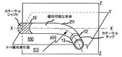
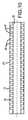
以下で参照する図面では、様々な図において同一の参照符号を用いて同一または同様の構成要素を特定する。図1は、近位ハンドル20から延びるチューブ状本体または軸21を備える偏向可能な電気生理学カテーテル3を全体的に示す。本明細書で使用され、当技術分野で通常使用されるように、「遠位」という用語は、一般に、カテーテル3の挿入端に向かって(すなわち、カテーテルの使用時に、心臓または他の標的組織に向かって)位置するチップ電極13などのシステムの構成要素を指すために用いられる。それに対して、「近位」という用語は、カテーテルの非挿入端に向かって(すなわち、カテーテルの使用時に、心臓または他の標的組織から離れて、もしくは反対に)位置する、または概して配向されるシステムの構成要素または部分を指すために一般に用いられる。カテーテル3を、心臓の電位図の記録、心臓アブレーション処置の動作、および他の同様の適用/処置などの様々な診断および治療の適用において使用することができる。 In the drawings referenced below, the same reference numbers are used in various figures to identify the same or similar components. FIG. 1 generally shows a
近位ハンドル20はアクチュエータ8を備え、このアクチュエータ8は、1つまたは複数の引張ワイヤ(図示せず)を介して、カテーテル3の遠位部分に組み込まれる偏向可能な遠位セグメント11に相互連結される。いくつかの実施形態では、引張ワイヤにより作動されたときに、カテーテル先端の動きを、一貫した繰返し可能な平面に制限して、カテーテルまたは他の医療デバイスの遠位先端の偏向運動を容易にすることが有利となり得る。すなわち、引張ワイヤを引いて(例えば、作動)カテーテルの遠位先端を偏向させたとき、カテーテル先端は、作動から作動へ繰返し可能な掃引面内で偏向することができる。しかしながら、現存のデバイスでは、カテーテルの先端は、しばしば、所望の掃引面から出ることができる。すなわち、現存のデバイスの遠位先端の偏向は、作動間で一貫していないことがある。したがって、いくつかの実施形態では、以下でさらに説明するように、カテーテルの遠位先端の動きを予測可能な一貫した方法で制限する偏向可能な遠位セグメントを提供することが有利となり得る。 The
図1に示すように、例示的なカテーテルの遠位先端は、アブレーション先端/電極13を備える。電極13の近位後方には、引張リング12および偏向可能な遠位セグメント11が位置する。偏向可能な遠位セグメント11の近位端は、カテーテル軸21の遠位端に連結される。そのようなカテーテルに関するさらなる詳細が、本明細書において完全に説明されるかのように参照により組み込まれている米国特許出願第13/838,124号に見出される。 As shown in FIG. 1, the distal tip of an exemplary catheter comprises an ablation tip /
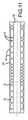
図2および図3は、カテーテル3の強調図である。カテーテル3は、近位ハンドル20から延びるチューブ状本体または軸21を含む。軸21の遠位には、偏向可能なセグメント111がある。比較的剛性のポリマーから構成される軸21と、より軟性のポリマーを含む偏向可能なセグメント111との間に、中間材料の剛性を有するポリマーから大部分が構成された軸移行領域22がある。偏向可能なセグメント111と遠位先端24とを、遠位移行領域23が連結する。図3は、XY偏向掃引面において偏向する偏向可能なセグメント111を示す。 2 and 3 are emphasized views of the
一般に、偏向可能なセグメントがその内部で最大曲げ剛性を有する偏向用平面は、セグメントの補強面を規定することができる。セグメントがその内部で最低曲げ剛性を有する偏向用平面は、仮想掃引面を規定することができる。掃引面は、一般的に補強面に垂直であり、両方の面が、偏向可能なセグメントの基準の長手方向軸(例えば、ニュートラル位置における中心X軸)をその長さに沿って通る。 In general, a deflection plane within which a deflectable segment has maximum bending stiffness can define a reinforcing surface of the segment. The deflection plane within which the segment has the lowest bending stiffness can define a virtual sweep plane. The sweep surface is generally perpendicular to the reinforcement surface, and both surfaces run along its length along the reference longitudinal axis of the deflectable segment (eg, the central X axis at the neutral position).
図4Aおよび図4Bは、本教示による偏向可能な遠位セグメントの例を示す。図4Aに示すように、ニュートラルな非偏向状態では、偏向可能な遠位セグメント211が、略チューブ状構造として、カテーテル軸10の遠位端とチップ電極13との間で延びている。一般に、カテーテル軸10は、偏向可能な遠位セグメント211よりも剛性が高い。例えば、カテーテル軸10を、近位ハンドル20(図4Aおよび図4Bには示さず)まで延びることのできる線編組によって覆われた可撓性弾性材料から形成することができる。そのような構成は十分に理解されており、本明細書でさらに説明する必要はない。 4A and 4B show examples of deflectable distal segments according to the present teachings. As shown in FIG. 4A, in the neutral undeflected state, the deflectable
例示的な一実施形態では、軸10は、可撓性弾性材料を用いて作製される。軸10を、生体適合性ポリマーなどの、ヒトに使用するのに適した材料から作製することができる。適切なポリマーとしては、限定されないが、フルオロポリマー、ポリオレフィン、ポリエステル、ポリアミド、ポリカーボネート、ポリウレタン、ポリイミド、ポリスルホン、ポリケトン、液体結晶ポリマーなどを含む多くの熱可塑性物質などの当技術分野で周知のものが挙げられる。また、様々な熱可塑性エラストマー(TPE)材料は、限定されないが、熱可塑性ポリウレタン、ポリアミドベースのTPE、ポリエステルベースのTPE、熱可塑性ポリオレフィン、およびスチレンTPEから選択することができる。 In one exemplary embodiment,
電極13の近位後方には引張リング12が位置する。偏向可能なセグメント211を偏向させるために、引張ワイヤ(図示せず)が、カテーテルハンドル(例えば、図1に示すハンドル20)のアクチュエータ機構から延びて、チップ電極13の近位付近に位置する引張リング12に取り付けられる。 A
図4Bに示すように、遠位先端(例えば、チップ電極13)は、曲げ面または掃引面100(例えば、XY面)内で動かされる。そのような所望の掃引面への制限により、カテーテルの偏向間で一貫した予測可能な変位をもたらすことができる。 As shown in FIG. 4B, the distal tip (eg, tip electrode 13) is moved within the bending or sweeping surface 100 (eg, XY plane). Such restriction to the desired sweep surface can result in consistent and predictable displacement between catheter deflections.
先行技術の偏向可能なセグメントは、望ましくないものであり得る何らかの面外の動きを可能にするものであった。このような問題を克服し、面外の偏向を最小にするために、本明細書で開示された偏向可能な遠位セグメント211は、異方的な曲げ剛性を有して、セグメント211の偏向を所望の平面(例えば、掃引面100)に分離することを容易にする。このようにして、そのニュートラル位置で、偏向可能なセグメント211は、指定された偏向掃引面、すなわちXY面に垂直なZ−Z軸の周りのセクション曲げ剛性の最少曲げモーメントを有する。 Prior art deflectable segments have allowed some out-of-plane movement that may be undesirable. In order to overcome such problems and minimize out-of-plane deflection, the deflectable
図5に示すように、偏向可能なセグメント211は、望ましい構成の滑らかな湾曲、偏向平面性、および操作の容易さをもたらす、噛み合った波形チューブ状構造を含む。セグメント211の波形構造はまた、ねじれ傾向を減らし、軸10からチップ電極13への高いトルク伝達を可能にする。 As shown in FIG. 5, the
図5は、2つの波形層14、15を含む偏向可能なセグメント211を示す。偏向可能なセグメント211は、第1の波形内層15および第2の波形外層14を含む。層14、15を、化学的に適合性のある熱可塑性エラストマー材料から作ることができる。層14、15は、異なる剛性(または可撓性または硬度)を有することができ、異なる溶解(または軟化)温度をさらに有することができる。熱可塑性エラストマー材料を、市販のポリ(エーテルブロックアミド)コポリマー(Pebax(登録商標)およびVestamid(登録商標)Eなど)、熱可塑性ポリウレタンエラストマー(Pellethane(登録商標)、Tecoflex(登録商標)、Tecoplast(登録商標)、Tecothane(登録商標)、Carbothane(登録商標)、Elasthane(登録商標)、Bionate(登録商標)、Biospan(登録商標)、Pursil(登録商標)、およびCarbosil(登録商標)など)、ポリエステルベースの熱可塑性エラストマー(Hytrel(登録商標)およびArnitel(登録商標)など)、ポリアミド(PA11、PA12、PA612など)、PETおよびPBTなどのポリエステル、ポリ(ビスフェノールA炭素)などから選択することができる。いくつかの実施形態では、熱可塑性エラストマー材料はPA11、PA12、およびPA612から選択される。 FIG. 5 shows a
偏向可能なセグメント211を製造するために、一貫した均一な波形パターンまたは軸方向に変化するパターン(例えば、図11に示す)を有することのできる内層15を、射出成形、圧縮成形、または3D印刷を用いて、外層14よりも高い溶解(または軟化)温度を有するポリマーから作製することができる。内層15は、中心ルーメン30を有する波形チューブ状構造を形成する。第2の外層14を、内層15よりも低い溶解(または軟化)温度を有する他のポリマーのチューブに予め押し出し、その後、予め成形された内層15に当てることができる。熱融着またはリフロープロセスにかけたとき、外層14は波形内層15の谷に埋め込まれ、内層15の波形面に付着する。最終的に、層14、15は、分離できない偏向可能なセグメントに組み込まれる。層14の波形は層15の波形と補完的であってよいが、「補完的」という用語は、層14、15の波形間に間隙がないことを意味するのではないことを理解されたい。実際に、層14、15の間に間隙空間が残ることが考えられる。 To produce the
層14、15の接合を容易にするために、いくつかの実施形態では、収縮チューブを第2の外層14に当て、金属ロッドを内層15のルーメン30に挿入することができる。収縮チューブを均一に加熱したとき、外層14は溶解して、収縮チューブから生じる内方への収縮圧力によって内層15の波形を埋め、金属ロッドは、中心ルーメン30の完全性を維持する。プロセス中、予め成形された内層15は、融点がより高いため、固体状態のままとなる。 In order to facilitate joining of the
予め成形された内層15と予め押し出された外層14との適切な熱融着を達成するために、内層15の溶解(または軟化)温度は、外層14の溶解(または軟化)温度よりも少なくとも10℃高くなければならない。いくつかの実施形態では、内層の溶解(または軟化)温度は、外層14の溶解(または軟化)温度よりも約20〜30℃高い。例えば、175℃〜180℃の溶解温度を有するPA12を内層15に使用することができ、Pebax(登録商標)5533 SA 01(約160℃の溶解温度を有する)またはPebax(登録商標)4033 SA 01(約147℃の溶解温度を有する)またはPebax(登録商標)3533 SA 01(約144℃の溶解温度を有する)などのポリ(エーテルブロックアミド)コポリマー(PEBA)を外層14として使用することができる。 In order to achieve adequate thermal fusion between the pre-formed
別の例では、内層15をPebax(登録商標)7233 SA 01から作ることができ、外層14をPebax(登録商標)4033 SA 01またはPebax(登録商標)3533 SA 01またはPebax(登録商標)2533 SA 01から作ることができる。 In another example, the
別の例では、内層15はPA11から作られ、外層14は、Pellethane(登録商標)2363−90AEまたはPellethane(登録商標)2363−80AEなどのポリテトラメチレングリコールベースのポリウレタンエラストマーから作られる。 In another example, the
別の実施形態では、内層15および外層14のポリマーを、明らかに異なる硬度を有するが、溶解加工のための同様の軟化温度を有するように選択することができる。そのような実施形態では、適切なウレタン接着剤およびシリコーン接着剤などの可撓性の高いエラストマー接着層を内層15と外層14との間に導入して、層15、14の補完的なピーク(またはリッジ)およびトラフ(または谷)間の間隙を埋めることができる。接着剤の硬化温度は、本体材料を軟化させるものであってはならない。 In another embodiment, the polymers of the
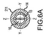
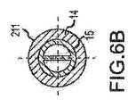
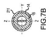
図5に示すように、偏向可能なセグメント211は、参照により本明細書に組み込まれている米国特許第7,985,215号に開示されたような補強要素16を有することができる。補強要素16は、偏向可能なセグメント211の周囲材料のヤング率よりも高いヤング率を有する。 As shown in FIG. 5, the
補強要素16は、偏向可能なセグメント211の長さ全体にわたって延びてもよく、かつ/または複数の補強要素16を、例えば、直列および/または並列に配置してもよい。1つの配置では、補強要素16は、偏向可能なセグメント211を形成する材料のヤング率よりも高いヤング率を有する。そのような配置では、補強要素16を、例えば、比較的剛性のポリマー材料および/または金属材料から形成することができる。いずれの配置においても、補強要素16の横断面は、第2の重心軸周りの領域慣性モーメントよりも大きい第1の重心軸周りの領域慣性モーメントを有することができる。これに関し、補強要素16は、第1の重心軸に平行な平面における曲げまたは偏向を可能にすると共に、別の平面における曲げを大幅に制限することができる。したがって、そのような補強要素16を偏向可能な遠位セグメント211の補強面付近に配置して、面外の動きを防止すると共に面内の動き(例えば、掃引面の動き)を可能にすることができる。 The reinforcing
図6A、図6B、図7A、および図7Bは、図5に示す、補強要素16を備える偏向可能なセグメント211の様々な横断面図である。図6Aおよび図7Aでは、補強要素16は別個の剛性で薄型の中心要素であり、この中心要素を、米国特許第7,985,215号に開示された内層15に挿入し組み込むことができる。補強要素16は、掃引面、すなわち、XY面内における偏向平面性の向上を助ける。図6Aおよび図7Aに示す補強要素16を、層15または層14よりも硬度の高い剛性の熱可塑性物質から作ることができる。いくつかの実施形態では、補強要素16は薄いシートメタルである。図6Bおよび図7Bに示す代替実施形態では、補強要素16は予め成形された内層15の一部である。 6A, 6B, 7A, and 7B are various cross-sectional views of the
したがって、カテーテル軸を補強するために通常使用される、鋼、ステンレス鋼、NiTi合金、タングステンなどを含む金属または金属合金から、補強要素16を作ることができる。また、それらの硬化材料は、ポリカーボネート、ナイロン、ポリエステル、ポリウレタン、ナイロンベースのコポリマー、ポリスチレン、ポリ(メチルメタクリレート)、ポリスルホン、液体結晶ポリマーなどのエンジニアリングポリマーであってよい。 Thus, the reinforcing
補強要素16は、ニュートラルな面内曲げ軸、すなわちZ軸近くに配置される。したがって、補強要素16は、ニュートラルな面内曲げ軸、すなわちZ軸の周りの面内曲げ剛性に対してほとんど寄与しない。しかしながら、補強要素16のヤング率が高いことにより、補強要素16は、ニュートラルな面外曲げ軸、すなわちX軸およびY軸の周りの面外曲げ剛性を増加させる。 The reinforcing
図8は、偏向可能なセグメント311の一部または全部の内部へ軸方向に延びる少なくとも1つの金属編組アセンブリ18を有する偏向可能なセグメント311を示す。金属編組アセンブリ18は、編組線のメッシュであってよい。金属編組アセンブリ18を、ステンレス鋼線から形成してもよい。金属編組アセンブリを、使い捨てコア上に別個に形成して、偏向可能なセグメントの内層15の周りに滑らせてもよい。当業者は、カテーテル構成における編組アセンブリ18の使用に精通しているため、本明細書でさらに説明する必要はない。 FIG. 8 shows the
図9〜図11は、偏向可能な本体211の波形内層15の考えられる様々な輪郭を示す。波形は、半円形、矩形、三角形、台形、正弦曲線、波状などの様々な規則的または不規則な幾何形状を取ることかできる。図9は半円形の変動を示し、図10は矩形の変動を示し、図11は変化する軸方向繰返しパターンを示す。図示したように、波形外形は偏向可能なセグメント211全体を通して均一のままであっても、軸方向に変化してもよい。波形外形は、変化する場合、繰返しパターンであっても非繰返し設計であってもよい。 9 to 11 show various possible contours of the corrugated
本開示の3つの実施形態をある程度の具体性を持って上記のとおり記載したが、当業者であれば添付されたクレームで規定される本発明の精神及び範囲から逸脱することなく開示された実施形態に対して種々の変更を加えることができる。すべての方向の参照(例えば、時計回りに、水平方向、垂直方向、上、下、下、上、右方向、左方向、右、左、下方向、上方向、下側、上側、および反時計回り)は、読者の本発明についての理解を助けるべく、識別目的で使用されているに過ぎず、特に本発明の位置、方向又は使用に関して制限を与えるものではない。結合に関する参照(例えば、取り付けられる、結合される、接続されるなど)は、広義に解釈されるべきであり、要素の接続部の中間部材や、要素間の相対運動の中間部材を包含している。このように、結合に関する参照は、必ずしも直接的に結合される2つの要素や互いに固定された2つの要素を必ずしも推論するものではない。 While the three embodiments of the present disclosure have been described with some specificity as described above, those skilled in the art will recognize the implementation disclosed without departing from the spirit and scope of the present invention as defined by the appended claims. Various changes can be made to the form. References in all directions (eg, clockwise, horizontal, vertical, up, down, down, up, right, left, right, left, down, up, down, up, and counterclockwise Is only used for identification purposes to assist the reader in understanding the present invention, and is not particularly restrictive regarding the position, orientation, or use of the present invention. References to coupling (eg, attached, coupled, connected, etc.) should be interpreted broadly, including intermediate members of element connections and intermediate members of relative motion between elements. Yes. Thus, a reference to coupling does not necessarily infer two elements that are directly coupled or two elements that are fixed together.
添付の図面、上記説明に含まれるまたは示される全ての事項は例示にすぎず、限定するものとして解釈されるべきでない。細部又は構造の変更は、添付の特許請求の範囲に規定される本開示の精神から逸脱することなく行うことができる。 All matters contained in or shown in the accompanying drawings and in the above description are illustrative only and should not be construed as limiting. Changes in detail or structure may be made without departing from the spirit of the present disclosure as defined in the appended claims.
本明細書中に参照により全体として又はその一部が組み込まれると称される、いかなる特許、出版物、もしくは他の開示マテリアルは、既存の定義、ステートメント、または本明細書おけるその他の本明細書に組み込まれるその他の開示マテリアルと抵触しない範囲においてのみ、参照により本明細書に組み込まれる。また、必要な範囲内において、本明細書に明示的に記載した開示は、本明細書に参照により組み込まれる全てのマテリアルよりも優先される。本明細書中に参照により全体として又はその一部が組み込まれると称される、いかなる特許、出版物、もしくは他の開示マテリアルであって、既存の定義、記述、または本明細書に記載の他の開示マテリアルと抵触するマテリアルは、その組み込まれたマテリアルと既存の開示マテリアルとの間に抵触を生じない範囲で組み込まれる。 Any patents, publications, or other disclosure materials referred to herein as incorporated in whole or in part by reference are subject to existing definitions, statements, or other specifications herein. Is incorporated herein by reference only to the extent that it does not conflict with other disclosed materials incorporated into. Also, to the extent necessary, the disclosure expressly set forth herein takes precedence over any material incorporated by reference herein. Any patent, publication, or other disclosure material referred to in this specification, which is incorporated by reference in its entirety or in part, including any existing definitions, descriptions, or other Any material that conflicts with any of the disclosed materials is incorporated to the extent that there is no conflict between the incorporated material and the existing disclosed material.
本明細書中に参照により全体として又はその一部が組み込まれると称される、いかなる特許、出版物、もしくは他の開示マテリアルは、既存の定義、ステートメント、または本明細書おけるその他の本明細書に組み込まれるその他の開示マテリアルと抵触しない範囲においてのみ、参照により本明細書に組み込まれる。また、必要な範囲内において、本明細書に明示的に記載した開示は、本明細書に参照により組み込まれる全てのマテリアルよりも優先される。本明細書中に参照により全体として又はその一部が組み込まれると称される、いかなる特許、出版物、もしくは他の開示マテリアルであって、既存の定義、記述、または本明細書に記載の他の開示マテリアルと抵触するマテリアルは、その組み込まれたマテリアルと既存の開示マテリアルとの間に抵触を生じない範囲で組み込まれる。
以下の項目は、国際出願時の特許請求の範囲に記載の要素である。
(項目1)
近位部分および遠位部分を有するカテーテル本体と、
前記遠位部分内の偏向可能なセグメントであって、中心ルーメンを含み、第1の波形面を有する第1の層および第2の波形面を有する第2の層を含み、前記第1の波形面および前記第2の波形面が隣接する偏向可能なセグメントと
を備えるカテーテル。
(項目2)
前記偏向可能なセグメントが略チューブ状である、項目1に記載のカテーテル。
(項目3)
前記第1の波形面が複数のトラフおよびリッジを含み、前記第2の波形面が第2の複数のトラフおよびリッジを含み、前記第1の複数のトラフおよびリッジが前記第2の複数のトラフおよびリッジと補完的である、項目1に記載のカテーテル。
(項目4)
前記第1の波形面および前記第2の波形面が共に接合される、項目4に記載のカテーテル。
(項目5)
前記第1の層および前記第2の層が、化学的に適合性のある熱可塑性エラストマー材料を含む、項目1に記載のカテーテル。
(項目6)
前記第1の層と前記第2の層とが異なる融点を有する、項目5に記載のカテーテル。
(項目7)
前記第1の層の融点が、前記第2の層の融点と20〜30度異なる、項目6に記載のカテーテル。
(項目8)
前記第1の層がポリアミド12から構成され、前記第2の層がポリ(エーテルブロックアミド)コポリマーから構成される、項目6に記載のカテーテル。
(項目9)
前記第1の層の融点が、前記第2の層の融点と20〜30度異なる、項目8に記載のカテーテル。
(項目10)
前記第1の層がポリアミド12から構成され、前記第2の層がポリ(エーテルブロックアミド)コポリマーから構成される、項目8に記載のカテーテル。
(項目11)
前記第1の層の融点が、前記第2の層の融点よりも高い、項目8に記載のカテーテル。
(項目12)
前記第1の層の融点が、前記第2の層の融点よりも低い、項目8に記載のカテーテル。
(項目13)
近位部分および遠位部分を有するカテーテル本体と、
前記遠位部分内の偏向可能なセグメントであって、中心ルーメンを含み、第1の波形面を有する第1の層および第2の波形面を有する第2の層を含み、前記第1の波形面および前記第2の波形面が隣接する偏向可能なセグメントと、
前記カテーテル本体の遠位端に配置されたチップ電極と、
前記偏向可能なセグメントの遠位部分と前記チップ電極との間に配置された環状リング、ならびに前記カテーテル本体の近位部分から延びて前記環状リングに相互連結される第1の引張ワイヤおよび第2の引張ワイヤを含む偏向作動構造と
を備えるカテーテル。
(項目14)
前記カテーテルが、前記偏向可能なセグメントの長さの一部に沿って配置された補強要素をさらに備える、項目13に記載のカテーテル。
(項目15)
近位部分および遠位部分を有するカテーテルであって、
偏向可能な遠位セグメントであって、内部ルーメンを含み、近位端および遠位端を含み、第1の波形面を有する第1の層および第2の波形面を有する第2の層を含み、前記第1の波形面および前記第2の波形面が隣接する偏向可能なセグメントと、
内部ルーメンを含み、前記偏向可能なセグメントの前記遠位端に配置されたチップ電極であって、前記チップ電極の前記内部ルーメンが前記偏向可能なセグメントの中心ルーメンと位置合わせされ連通するチップ電極と
を備えるカテーテル。
(項目16)
前記第1の波形面が複数のトラフおよびリッジを含み、前記第2の波形面が第2の複数のトラフおよびリッジを含み、前記第1の複数のトラフおよびリッジが前記第2の複数のトラフおよびリッジと補完的である、項目15記載のカテーテル。
(項目17)
前記複数のトラフおよびリッジが、半円形の変動、矩形の変動、および変化する軸方向繰返しパターンから選択される、項目16に記載のカテーテル。
(項目18)
前記第1の層および前記第2の層が、化学的に適合性のある熱可塑性エラストマー材料を含む、項目15に記載のカテーテル。
(項目19)
前記第1の層と前記第2の層とが異なる融点を有する、項目18に記載のカテーテル。
(項目20)
前記第1の層の融点が、前記第2の層の融点よりも約20〜30度高いまたは低い、項目19に記載のカテーテル。
(項目21)
前記第1の層がポリアミド12から構成され、前記第2の層がポリ(エーテルブロックアミド)コポリマーから構成される、項目19に記載のカテーテル。
Any patents, publications, or other disclosure materials referred to herein as incorporated in whole or in part by reference are subject to existing definitions, statements, or other specifications herein. Is incorporated herein by reference only to the extent that it does not conflict with other disclosed materials incorporated into. Also, to the extent necessary, the disclosure expressly set forth herein takes precedence over any material incorporated by reference herein. Any patent, publication, or other disclosure material referred to in this specification, which is incorporated by reference in its entirety or in part, including any existing definitions, descriptions, or other Any material that conflicts with any of the disclosed materials is incorporated to the extent that there is no conflict between the incorporated material and the existing disclosed material.
The following items are the elements described in the claims at the time of international application.
(Item 1)
A catheter body having a proximal portion and a distal portion;
A deflectable segment in the distal portion, comprising a central lumen, including a first layer having a first corrugated surface and a second layer having a second corrugated surface, the first corrugated A deflectable segment adjacent to the surface and the second corrugated surface;
A catheter comprising:
(Item 2)
Item 2. The catheter of item 1, wherein the deflectable segment is generally tubular.
(Item 3)
The first corrugated surface includes a plurality of troughs and ridges, the second corrugated surface includes a second plurality of troughs and ridges, and the first plurality of troughs and ridges includes the second plurality of troughs. And the catheter of item 1, which is complementary to Ridge.
(Item 4)
Item 5. The catheter of item 4, wherein the first corrugated surface and the second corrugated surface are joined together.
(Item 5)
The catheter of claim 1, wherein the first layer and the second layer comprise a chemically compatible thermoplastic elastomer material.
(Item 6)
Item 6. The catheter according to Item 5, wherein the first layer and the second layer have different melting points.
(Item 7)
(Item 8)
(Item 9)
Item 9. The catheter according to Item 8, wherein the melting point of the first layer differs from the melting point of the second layer by 20 to 30 degrees.
(Item 10)
Item 9. The catheter of item 8, wherein the first layer is composed of
(Item 11)
Item 9. The catheter according to Item 8, wherein the melting point of the first layer is higher than the melting point of the second layer.
(Item 12)
Item 9. The catheter according to Item 8, wherein the melting point of the first layer is lower than the melting point of the second layer.
(Item 13)
A catheter body having a proximal portion and a distal portion;
A deflectable segment in the distal portion, comprising a central lumen, including a first layer having a first corrugated surface and a second layer having a second corrugated surface, the first corrugated A deflectable segment with adjacent surfaces and said second corrugated surface;
A tip electrode disposed at a distal end of the catheter body;
An annular ring disposed between the distal portion of the deflectable segment and the tip electrode, and a first tension wire and a second extending from the proximal portion of the catheter body and interconnected to the annular ring Deflection actuation structure including a pull wire
A catheter comprising:
(Item 14)
14. A catheter according to
(Item 15)
A catheter having a proximal portion and a distal portion,
A deflectable distal segment comprising an inner lumen, comprising a proximal end and a distal end, comprising a first layer having a first corrugated surface and a second layer having a second corrugated surface A deflectable segment in which the first corrugated surface and the second corrugated surface are adjacent;
A tip electrode including an inner lumen and disposed at the distal end of the deflectable segment, wherein the inner lumen of the tip electrode is aligned with and communicates with a central lumen of the deflectable segment;
A catheter comprising:
(Item 16)
The first corrugated surface includes a plurality of troughs and ridges, the second corrugated surface includes a second plurality of troughs and ridges, and the first plurality of troughs and ridges includes the second plurality of troughs. And the catheter of
(Item 17)
The catheter of
(Item 18)
16. The catheter of
(Item 19)
Item 19. The catheter of
(Item 20)
The catheter of item 19, wherein the melting point of the first layer is about 20-30 degrees higher or lower than the melting point of the second layer.
(Item 21)
20. A catheter according to item 19, wherein the first layer is composed of
Claims (21)
Translated fromJapanese前記遠位部分内の偏向可能なセグメントであって、中心ルーメンを含み、第1の波形面を有する第1の層および第2の波形面を有する第2の層を含み、前記第1の波形面および前記第2の波形面が隣接する偏向可能なセグメントと
を備えるカテーテル。A catheter body having a proximal portion and a distal portion;
A deflectable segment in the distal portion, comprising a central lumen, including a first layer having a first corrugated surface and a second layer having a second corrugated surface, the first corrugated And a deflectable segment adjacent to said second corrugated surface.
前記遠位部分内の偏向可能なセグメントであって、中心ルーメンを含み、第1の波形面を有する第1の層および第2の波形面を有する第2の層を含み、前記第1の波形面および前記第2の波形面が隣接する偏向可能なセグメントと、
前記カテーテル本体の遠位端に配置されたチップ電極と、
前記偏向可能なセグメントの遠位部分と前記チップ電極との間に配置された環状リング、ならびに前記カテーテル本体の近位部分から延びて前記環状リングに相互連結される第1の引張ワイヤおよび第2の引張ワイヤを含む偏向作動構造と
を備えるカテーテル。A catheter body having a proximal portion and a distal portion;
A deflectable segment in the distal portion, comprising a central lumen, including a first layer having a first corrugated surface and a second layer having a second corrugated surface, the first corrugated A deflectable segment with adjacent surfaces and said second corrugated surface;
A tip electrode disposed at a distal end of the catheter body;
An annular ring disposed between the distal portion of the deflectable segment and the tip electrode, and a first tension wire and a second extending from the proximal portion of the catheter body and interconnected to the annular ring And a deflection actuating structure including a tension wire.
偏向可能な遠位セグメントであって、内部ルーメンを含み、近位端および遠位端を含み、第1の波形面を有する第1の層および第2の波形面を有する第2の層を含み、前記第1の波形面および前記第2の波形面が隣接する偏向可能なセグメントと、
内部ルーメンを含み、前記偏向可能なセグメントの前記遠位端に配置されたチップ電極であって、前記チップ電極の前記内部ルーメンが前記偏向可能なセグメントの中心ルーメンと位置合わせされ連通するチップ電極と
を備えるカテーテル。A catheter having a proximal portion and a distal portion,
A deflectable distal segment comprising an inner lumen, comprising a proximal end and a distal end, comprising a first layer having a first corrugated surface and a second layer having a second corrugated surface A deflectable segment in which the first corrugated surface and the second corrugated surface are adjacent;
A tip electrode including an inner lumen and disposed at the distal end of the deflectable segment, wherein the inner lumen of the tip electrode is aligned with and communicates with a central lumen of the deflectable segment; A catheter comprising:
Applications Claiming Priority (3)
| Application Number | Priority Date | Filing Date | Title |
|---|---|---|---|
| US201361920603P | 2013-12-24 | 2013-12-24 | |
| US61/920,603 | 2013-12-24 | ||
| PCT/US2014/067307WO2015099935A1 (en) | 2013-12-24 | 2014-11-25 | Deflectable catheter bodies with corrugated structures |
Publications (1)
| Publication Number | Publication Date |
|---|---|
| JP2017504390Atrue JP2017504390A (en) | 2017-02-09 |
Family
ID=52103015
Family Applications (1)
| Application Number | Title | Priority Date | Filing Date |
|---|---|---|---|
| JP2016541541APendingJP2017504390A (en) | 2013-12-24 | 2014-11-25 | A deflectable catheter body having a corrugated structure |
Country Status (5)
| Country | Link |
|---|---|
| US (1) | US10610293B2 (en) |
| EP (1) | EP3065806B1 (en) |
| JP (1) | JP2017504390A (en) |
| CN (1) | CN105848704A (en) |
| WO (1) | WO2015099935A1 (en) |
Families Citing this family (21)
| Publication number | Priority date | Publication date | Assignee | Title |
|---|---|---|---|---|
| US9243726B2 (en) | 2012-10-03 | 2016-01-26 | Aarne H. Reid | Vacuum insulated structure with end fitting and method of making same |
| CN104984458A (en)* | 2015-07-21 | 2015-10-21 | 中国人民解放军第三军医大学第二附属医院 | Medical operation sheath and use method of same |
| US10497908B2 (en) | 2015-08-24 | 2019-12-03 | Concept Group, Llc | Sealed packages for electronic and energy storage devices |
| EP4032578A1 (en) | 2016-07-13 | 2022-07-27 | Perfuze Limited | High flexibility, kink resistant catheter shaft |
| WO2018055706A1 (en)* | 2016-09-21 | 2018-03-29 | 朝日インテック株式会社 | Catheter and balloon catheter |
| JP6241907B1 (en)* | 2016-10-04 | 2017-12-06 | 朝日インテック株式会社 | Catheter and balloon catheter |
| WO2018093773A1 (en) | 2016-11-15 | 2018-05-24 | Reid Aarne H | Multiply-insulated assemblies |
| CA3043915A1 (en) | 2016-11-15 | 2018-05-24 | Concept Group Llc | Enhanced vacuum-insulated articles with microporous insulation |
| US20200054864A1 (en)* | 2017-03-20 | 2020-02-20 | Mencius Medical B.V. | Guide wire-catheter assembly |
| US11320086B2 (en) | 2017-08-25 | 2022-05-03 | Concept Group Llc | Multiple geometry and multiple material insulated components |
| JP2018057874A (en)* | 2017-11-01 | 2018-04-12 | 朝日インテック株式会社 | Catheter and balloon catheter |
| CN111465420B (en) | 2017-12-15 | 2023-04-18 | 佩尔福兹有限公司 | Improved catheter and apparatus and system incorporating same |
| US10960147B2 (en)* | 2018-04-20 | 2021-03-30 | Flextronics Ap, Llc | Flex needle |
| WO2020176774A1 (en)* | 2019-02-27 | 2020-09-03 | Concept Group Llc | Vacuum-insulated medical devices |
| DE102019112248A1 (en) | 2019-05-10 | 2020-11-12 | Biotronik Se & Co. Kg | Multi-lumen body for a medical device |
| US11413454B2 (en)* | 2019-06-25 | 2022-08-16 | St. Jude Medical, Cardiology Division, Inc. | Delivery device having a deflectable and peelable mapping guide sheath for his bundle pacing |
| EP3858424A1 (en)* | 2020-01-29 | 2021-08-04 | BIOTRONIK SE & Co. KG | Tube assembly and medical product comprising such a tube assembly |
| DE102020111455A1 (en) | 2020-04-27 | 2021-10-28 | Schölly Fiberoptic GmbH | Flexible endoscope based on an investment material |
| DE102020111458A1 (en)* | 2020-04-27 | 2021-10-28 | Schölly Fiberoptic GmbH | Flexible endoscope with a skeletal structure |
| US12220131B2 (en)* | 2022-01-06 | 2025-02-11 | DePuy Synthes Products, Inc. | Delivery and detachment system imposing a friction force on a securement wire to minimize movement of an implantable intravascular device |
| US20240156524A1 (en)* | 2022-11-11 | 2024-05-16 | Biosense Webster (Israel) Ltd. | Electrode catheter with corrugated support structure |
Citations (7)
| Publication number | Priority date | Publication date | Assignee | Title |
|---|---|---|---|---|
| JPH03128024A (en)* | 1989-10-13 | 1991-05-31 | Machida Seisakusho:Kk | Angle for curving operation device |
| JPH07265432A (en)* | 1994-03-29 | 1995-10-17 | Hanako Medical Kk | Work hardening type non-shape memory alloy catheter |
| US20090171348A1 (en)* | 2007-12-28 | 2009-07-02 | Xiaoping Guo | Deflectable catheter with distal deflectable segment |
| JP2009533174A (en)* | 2006-04-13 | 2009-09-17 | ボストン サイエンティフィック リミテッド | Medical device containing shape memory material |
| JP2009537244A (en)* | 2006-05-16 | 2009-10-29 | セント・ジュード・メディカル・エイトリアル・フィブリレーション・ディヴィジョン・インコーポレーテッド | Steerable catheter using a flat pull wire and method of making the same |
| US20100168717A1 (en)* | 2008-12-30 | 2010-07-01 | Grasse Martin M | Multi-lumen medical devices and methods of manufacturing same |
| JP2012518470A (en)* | 2009-02-20 | 2012-08-16 | ボストン サイエンティフィック サイムド,インコーポレイテッド | Asymmetric bi-directional movable catheter sheath |
Family Cites Families (20)
| Publication number | Priority date | Publication date | Assignee | Title |
|---|---|---|---|---|
| EP0422887B1 (en)* | 1989-10-13 | 1996-12-11 | Kabushiki Kaisha Machida Seisakusho | Bending device |
| DE3935256C1 (en)* | 1989-10-23 | 1991-01-03 | Bauerfeind, Peter, Dr., 8264 Waldkraiburg, De | |
| US5527325A (en)* | 1993-07-09 | 1996-06-18 | Device For Vascular Intervention, Inc. | Atherectomy catheter and method |
| US6072154A (en) | 1996-09-05 | 2000-06-06 | Medtronic, Inc. | Selectively activated shape memory device |
| US6440120B1 (en)* | 1998-09-02 | 2002-08-27 | Embol-X, Inc. | Bendable shape-retaining cannula |
| US6203507B1 (en) | 1999-03-03 | 2001-03-20 | Cordis Webster, Inc. | Deflectable catheter with ergonomic handle |
| US6585718B2 (en) | 2001-05-02 | 2003-07-01 | Cardiac Pacemakers, Inc. | Steerable catheter with shaft support system for resisting axial compressive loads |
| US7998112B2 (en) | 2003-09-30 | 2011-08-16 | Abbott Cardiovascular Systems Inc. | Deflectable catheter assembly and method of making same |
| US7465288B2 (en) | 2005-06-28 | 2008-12-16 | St. Jude Medical, Atrial Fibrillation Division, Inc. | Actuation handle for a catheter |
| US20070270679A1 (en) | 2006-05-17 | 2007-11-22 | Duy Nguyen | Deflectable variable radius catheters |
| US8979837B2 (en) | 2007-04-04 | 2015-03-17 | St. Jude Medical, Atrial Fibrillation Division, Inc. | Flexible tip catheter with extended fluid lumen |
| US8187267B2 (en) | 2007-05-23 | 2012-05-29 | St. Jude Medical, Atrial Fibrillation Division, Inc. | Ablation catheter with flexible tip and methods of making the same |
| US8226641B2 (en)* | 2007-12-21 | 2012-07-24 | St. Jude Medical, Atrial Fibrillation Division, Inc. | Medical catheter with deflection pull ring and distal tip attachment apparatus |
| WO2009097650A1 (en) | 2008-02-07 | 2009-08-13 | Commonwealth Scientific And Industrial Research Organisation | Expandable catheter |
| US8118775B2 (en) | 2008-09-09 | 2012-02-21 | Biosense Webster, Inc. | Deflectable catheter with bonded center strut and method of manufacture for same |
| TWI517833B (en)* | 2009-03-31 | 2016-01-21 | 東麗股份有限公司 | Shaft for ablation catheter with balloon and ablation catheter system |
| US10688278B2 (en) | 2009-11-30 | 2020-06-23 | Biosense Webster (Israel), Ltd. | Catheter with pressure measuring tip |
| US8374670B2 (en) | 2010-01-22 | 2013-02-12 | Biosense Webster, Inc. | Catheter having a force sensing distal tip |
| JP4679668B1 (en) | 2010-04-21 | 2011-04-27 | 日本ライフライン株式会社 | catheter |
| EP3583976B1 (en) | 2013-03-16 | 2023-03-08 | Clph, Llc | Steerable catheters and methods for making them |
- 2014
- 2014-11-25JPJP2016541541Apatent/JP2017504390A/enactivePending
- 2014-11-25EPEP14812693.1Apatent/EP3065806B1/enactiveActive
- 2014-11-25USUS15/106,155patent/US10610293B2/enactiveActive
- 2014-11-25CNCN201480070598.XApatent/CN105848704A/enactivePending
- 2014-11-25WOPCT/US2014/067307patent/WO2015099935A1/enactiveApplication Filing
Patent Citations (7)
| Publication number | Priority date | Publication date | Assignee | Title |
|---|---|---|---|---|
| JPH03128024A (en)* | 1989-10-13 | 1991-05-31 | Machida Seisakusho:Kk | Angle for curving operation device |
| JPH07265432A (en)* | 1994-03-29 | 1995-10-17 | Hanako Medical Kk | Work hardening type non-shape memory alloy catheter |
| JP2009533174A (en)* | 2006-04-13 | 2009-09-17 | ボストン サイエンティフィック リミテッド | Medical device containing shape memory material |
| JP2009537244A (en)* | 2006-05-16 | 2009-10-29 | セント・ジュード・メディカル・エイトリアル・フィブリレーション・ディヴィジョン・インコーポレーテッド | Steerable catheter using a flat pull wire and method of making the same |
| US20090171348A1 (en)* | 2007-12-28 | 2009-07-02 | Xiaoping Guo | Deflectable catheter with distal deflectable segment |
| US20100168717A1 (en)* | 2008-12-30 | 2010-07-01 | Grasse Martin M | Multi-lumen medical devices and methods of manufacturing same |
| JP2012518470A (en)* | 2009-02-20 | 2012-08-16 | ボストン サイエンティフィック サイムド,インコーポレイテッド | Asymmetric bi-directional movable catheter sheath |
Also Published As
| Publication number | Publication date |
|---|---|
| CN105848704A (en) | 2016-08-10 |
| US20160317220A1 (en) | 2016-11-03 |
| US10610293B2 (en) | 2020-04-07 |
| EP3065806B1 (en) | 2019-07-24 |
| EP3065806A1 (en) | 2016-09-14 |
| WO2015099935A1 (en) | 2015-07-02 |
Similar Documents
| Publication | Publication Date | Title |
|---|---|---|
| US10610293B2 (en) | Deflectable catheter bodies with corrugated tubular structures | |
| EP2736574B1 (en) | Steerable catheters | |
| JP5572171B2 (en) | Medical device having a laminate coated braid assembly | |
| EP2956197B1 (en) | Steerable medical device having multiple curve profiles | |
| JP5632007B2 (en) | Device for reducing axial contraction of catheter or sheath due to repeated bending | |
| JP6351956B2 (en) | A catheter with a flat beam deflected at the end | |
| JP7329442B2 (en) | Sheath visualization | |
| CN103282074B (en) | Steerable intraluminal devices and methods | |
| EP2732844B1 (en) | Catheter with flat beam providing nonsymmetrical curve bi-directional deflection | |
| US7993481B2 (en) | Catheter with embedded components and method of its manufacture | |
| CN108463265B (en) | Nondestructive connector and catheter using the same | |
| WO2016094938A1 (en) | An improved catheter and method of manufacture thereof | |
| US11890427B2 (en) | Medical device with non-metallic reinforcing layer | |
| US9993623B2 (en) | Guidewires with variable rigidity | |
| EP2635339B1 (en) | Steerable endoluminal devices | |
| WO2023086215A2 (en) | Multi-lumen catheter containing integral strut and method of its manufacture | |
| WO2024251535A1 (en) | Catheter segment and catheter comprising such segment |
Legal Events
| Date | Code | Title | Description |
|---|---|---|---|
| A521 | Request for written amendment filed | Free format text:JAPANESE INTERMEDIATE CODE: A523 Effective date:20160701 Free format text:JAPANESE INTERMEDIATE CODE: A523 Effective date:20160818 | |
| A621 | Written request for application examination | Free format text:JAPANESE INTERMEDIATE CODE: A621 Effective date:20160818 | |
| A131 | Notification of reasons for refusal | Free format text:JAPANESE INTERMEDIATE CODE: A131 Effective date:20170516 | |
| A977 | Report on retrieval | Free format text:JAPANESE INTERMEDIATE CODE: A971007 Effective date:20170519 | |
| A521 | Request for written amendment filed | Free format text:JAPANESE INTERMEDIATE CODE: A523 Effective date:20170809 | |
| A131 | Notification of reasons for refusal | Free format text:JAPANESE INTERMEDIATE CODE: A131 Effective date:20171205 | |
| A521 | Request for written amendment filed | Free format text:JAPANESE INTERMEDIATE CODE: A523 Effective date:20180226 | |
| A131 | Notification of reasons for refusal | Free format text:JAPANESE INTERMEDIATE CODE: A131 Effective date:20180703 | |
| A02 | Decision of refusal | Free format text:JAPANESE INTERMEDIATE CODE: A02 Effective date:20190219 |