JP2017223461A - Radar device and detection method - Google Patents
Radar device and detection methodDownload PDFInfo
- Publication number
- JP2017223461A JP2017223461AJP2016117102AJP2016117102AJP2017223461AJP 2017223461 AJP2017223461 AJP 2017223461AJP 2016117102 AJP2016117102 AJP 2016117102AJP 2016117102 AJP2016117102 AJP 2016117102AJP 2017223461 AJP2017223461 AJP 2017223461A
- Authority
- JP
- Japan
- Prior art keywords
- stationary object
- boundary
- doppler
- range
- region
- Prior art date
- Legal status (The legal status is an assumption and is not a legal conclusion. Google has not performed a legal analysis and makes no representation as to the accuracy of the status listed.)
- Ceased
Links
Images


Classifications
- G—PHYSICS
- G01—MEASURING; TESTING
- G01S—RADIO DIRECTION-FINDING; RADIO NAVIGATION; DETERMINING DISTANCE OR VELOCITY BY USE OF RADIO WAVES; LOCATING OR PRESENCE-DETECTING BY USE OF THE REFLECTION OR RERADIATION OF RADIO WAVES; ANALOGOUS ARRANGEMENTS USING OTHER WAVES
- G01S13/00—Systems using the reflection or reradiation of radio waves, e.g. radar systems; Analogous systems using reflection or reradiation of waves whose nature or wavelength is irrelevant or unspecified
- G01S13/02—Systems using reflection of radio waves, e.g. primary radar systems; Analogous systems
- G01S13/50—Systems of measurement based on relative movement of target
- G01S13/52—Discriminating between fixed and moving objects or between objects moving at different speeds
- G01S13/56—Discriminating between fixed and moving objects or between objects moving at different speeds for presence detection
- G—PHYSICS
- G01—MEASURING; TESTING
- G01S—RADIO DIRECTION-FINDING; RADIO NAVIGATION; DETERMINING DISTANCE OR VELOCITY BY USE OF RADIO WAVES; LOCATING OR PRESENCE-DETECTING BY USE OF THE REFLECTION OR RERADIATION OF RADIO WAVES; ANALOGOUS ARRANGEMENTS USING OTHER WAVES
- G01S13/00—Systems using the reflection or reradiation of radio waves, e.g. radar systems; Analogous systems using reflection or reradiation of waves whose nature or wavelength is irrelevant or unspecified
- G01S13/02—Systems using reflection of radio waves, e.g. primary radar systems; Analogous systems
- G01S13/50—Systems of measurement based on relative movement of target
- G01S13/58—Velocity or trajectory determination systems; Sense-of-movement determination systems
- G01S13/589—Velocity or trajectory determination systems; Sense-of-movement determination systems measuring the velocity vector
- G—PHYSICS
- G01—MEASURING; TESTING
- G01S—RADIO DIRECTION-FINDING; RADIO NAVIGATION; DETERMINING DISTANCE OR VELOCITY BY USE OF RADIO WAVES; LOCATING OR PRESENCE-DETECTING BY USE OF THE REFLECTION OR RERADIATION OF RADIO WAVES; ANALOGOUS ARRANGEMENTS USING OTHER WAVES
- G01S13/00—Systems using the reflection or reradiation of radio waves, e.g. radar systems; Analogous systems using reflection or reradiation of waves whose nature or wavelength is irrelevant or unspecified
- G01S13/02—Systems using reflection of radio waves, e.g. primary radar systems; Analogous systems
- G01S13/50—Systems of measurement based on relative movement of target
- G01S13/58—Velocity or trajectory determination systems; Sense-of-movement determination systems
- G01S13/60—Velocity or trajectory determination systems; Sense-of-movement determination systems wherein the transmitter and receiver are mounted on the moving object, e.g. for determining ground speed, drift angle, ground track
- G—PHYSICS
- G01—MEASURING; TESTING
- G01S—RADIO DIRECTION-FINDING; RADIO NAVIGATION; DETERMINING DISTANCE OR VELOCITY BY USE OF RADIO WAVES; LOCATING OR PRESENCE-DETECTING BY USE OF THE REFLECTION OR RERADIATION OF RADIO WAVES; ANALOGOUS ARRANGEMENTS USING OTHER WAVES
- G01S13/00—Systems using the reflection or reradiation of radio waves, e.g. radar systems; Analogous systems using reflection or reradiation of waves whose nature or wavelength is irrelevant or unspecified
- G01S13/88—Radar or analogous systems specially adapted for specific applications
- G01S13/93—Radar or analogous systems specially adapted for specific applications for anti-collision purposes
- G01S13/931—Radar or analogous systems specially adapted for specific applications for anti-collision purposes of land vehicles
Landscapes
- Engineering & Computer Science (AREA)
- Remote Sensing (AREA)
- Radar, Positioning & Navigation (AREA)
- Physics & Mathematics (AREA)
- Computer Networks & Wireless Communication (AREA)
- General Physics & Mathematics (AREA)
- Electromagnetism (AREA)
- Radar Systems Or Details Thereof (AREA)
Abstract
Translated fromJapaneseDescription
Translated fromJapanese本開示は、移動物体を検出するレーダ装置および検出方法に関する。 The present disclosure relates to a radar apparatus and a detection method for detecting a moving object.
従来、レーダ装置に関する様々な技術が開示されている。例えば、特許文献1には、レーダ装置が放射する同一ビーム幅内の同一レンジに、検出対象となる物体(以下、目標物)が複数存在する場合、各目標物の移動速度の差に基づくドップラ周波数の差をドップラフィルタで抽出し、各目標物を分離して検出するレーダ装置の技術が開示されている。 Conventionally, various techniques relating to radar devices have been disclosed. For example, in
しかしながら、特許文献1の技術では、目標物の移動速度がレーダ装置を搭載する車両等の移動速度と同等である場合、すなわち、目標物とレーダ装置との相対速度がゼロに近い場合、ドップラフィルタを用いた分離は困難である。また、目標物がクロスレンジ方向(目標物とレーダ装置とを結ぶ直線に略垂直な方向)に移動する場合、レーダ装置によって観測される目標物のドップラ周波数は、レーダ装置の周辺に静止して存在する建物等の物体(以下、周辺静止物という)のドップラ周波数と同等になるため、目標物を周辺静止物から分離して検出することが困難である。 However, in the technique of
本開示の非限定的な実施例は、クロスレンジ方向に移動する目標物を周辺静止物から分離して検出できるレーダ装置および検出方法を提供することである。 A non-limiting example of the present disclosure is to provide a radar apparatus and a detection method that can detect a target moving in a cross range direction separately from a surrounding stationary object.
本開示の一態様は、レーダ信号を送信する送信部と、物体によって前記レーダ信号が反射されたエコー信号を受信する受信部と、前記エコー信号を用いて、静止物が存在する領域の境界を検出する静止物境界検出部と、前記静止物が存在する領域の境界が時間変化する領域を検出し、前記時間変化する領域の移動方向が、前記受信部に対してクロスレンジ方向である場合、前記時間変化する領域を、移動する第1物体として検出する静止物境界変動検出部と、を備える移動体に設置されたレーダ装置である。 One aspect of the present disclosure includes a transmission unit that transmits a radar signal, a reception unit that receives an echo signal in which the radar signal is reflected by an object, and a boundary of a region where a stationary object exists using the echo signal. When the stationary object boundary detection unit to detect and a region where the boundary of the region where the stationary object exists is detected to change over time, and the moving direction of the time changing region is a cross range direction with respect to the receiving unit, It is a radar apparatus installed in a moving body including a stationary object boundary fluctuation detecting unit that detects the time-varying region as a moving first object.
本開示の一態様は、レーダ信号を送信し、物体によって前記レーダ信号が反射されたエコー信号を受信し、前記エコー信号を用いて、静止物が存在する領域の境界を検出し、前記静止物が存在する領域の境界が時間変化する領域を検出し、前記時間変化する領域の移動方向が、受信部に対してクロスレンジ方向である場合、前記時間変化する領域を、移動する第1物体として検出する、移動体に設置されたレーダ装置における検出方法である。 One aspect of the present disclosure transmits a radar signal, receives an echo signal in which the radar signal is reflected by an object, detects a boundary of a region where a stationary object exists using the echo signal, and detects the stationary object When a region where the boundary of the region where the signal exists changes with time is detected and the moving direction of the time changing region is a cross range direction with respect to the receiving unit, the time changing region is set as the first object to move. This is a detection method in a radar apparatus installed on a moving body for detection.
なお、これらの包括的または具体的な態様は、システム、集積回路、コンピュータプログラム、または、記録媒体で実現されてもよく、システム、装置、方法、集積回路、コンピュータプログラムおよび記録媒体の任意な組み合わせで実現されてもよい。 Note that these comprehensive or specific aspects may be realized by a system, an integrated circuit, a computer program, or a recording medium, and any combination of the system, apparatus, method, integrated circuit, computer program, and recording medium. It may be realized with.
本開示の一態様によれば、クロスレンジ方向に移動する目標物を周辺静止物から分離して検出できる。 According to one aspect of the present disclosure, a target moving in the cross range direction can be detected separately from a surrounding stationary object.
本開示の一態様における更なる利点および効果は、明細書および図面から明らかにされる。かかる利点および/または効果は、いくつかの実施形態並びに明細書および図面に記載された特徴によってそれぞれ提供されるが、1つまたはそれ以上の同一の特徴を得るために必ずしも全てが提供される必要はない。 Further advantages and effects in one aspect of the present disclosure will become apparent from the specification and drawings. Such advantages and / or effects are provided by some embodiments and features described in the description and drawings, respectively, but all need to be provided in order to obtain one or more identical features. There is no.
(本開示に至る経緯)
まず、本開示に至る経緯について説明する。本開示は、クロスレンジ方向(目標物とレーダ装置とを結ぶ直線に略垂直な方向)に移動する目標物を検出するレーダ装置および検出方法に関する。(Background to this disclosure)
First, the process leading to the present disclosure will be described. The present disclosure relates to a radar apparatus and a detection method for detecting a target moving in a cross range direction (a direction substantially perpendicular to a straight line connecting the target and the radar apparatus).
近年、車両の安全運転支援に関する技術開発が盛んである。車両の安全運転支援のためには、車両の周辺状況を的確に認識する技術が肝要である。車両の周辺状況を認識するためには、車両にレーダ装置を搭載することが知られている。 In recent years, technical development related to safe driving support for vehicles has been active. In order to support safe driving of a vehicle, a technique for accurately recognizing the surrounding situation of the vehicle is essential. In order to recognize the surrounding situation of a vehicle, it is known to mount a radar device on the vehicle.
車両は移動するため、車両の周辺状況は時々刻々と大きく変化する。そのため、車両に搭載されるレーダ装置が周辺状況を認識するために必要な演算量は、増加する傾向にある。一方で、レーダ装置のハードウェアリソースは限られているため、その限られたリソースを用いて周辺状況を認識するためには、演算の簡易化が必要とされる。 Since the vehicle moves, the situation around the vehicle changes greatly from moment to moment. Therefore, the amount of calculation required for the radar apparatus mounted on the vehicle to recognize the surrounding situation tends to increase. On the other hand, since the hardware resources of the radar apparatus are limited, in order to recognize the surrounding situation using the limited resources, it is necessary to simplify the calculation.
レーダ装置を用いて、簡易な演算で周辺状況を認識するためには、例えば、レーダ装置が、目標物と周辺静止物とを含む周辺の物体からの反射波を受信し、受信した反射波から抽出したドップラ周波数を用いて、移動する目標物と周辺静止物とを分離して検出するという方法が考えられる。 In order to recognize a surrounding situation with a simple calculation using a radar device, for example, the radar device receives a reflected wave from a surrounding object including a target object and a stationary stationary object, and receives the reflected wave from the received reflected wave. A method of separating and detecting a moving target object and a surrounding stationary object using the extracted Doppler frequency is conceivable.
図1は、ドップラ周波数を用いた目標物の検出方法を示す図である。図1に示す扇形の範囲Rは、車両に搭載されるレーダ装置の検知範囲を例示している。また、図1には、範囲R内を移動する目標物X(例えば、歩行者)が示される。 FIG. 1 is a diagram illustrating a target detection method using a Doppler frequency. The sector-shaped range R shown in FIG. 1 illustrates the detection range of the radar device mounted on the vehicle. Further, FIG. 1 shows a target X (for example, a pedestrian) that moves within a range R.
レーダ装置が観測可能なドップラ速度(ドップラ周波数を速度に変換した値)は、目標物Xの移動速度(移動ベクトル)のうち、目標物Xとレーダ装置とを結ぶ直線方向(以下、レンジ方向という)の速度成分である。レンジ方向の速度成分が大きい状況(図1において、目標物Xが範囲Rの両端付近を移動する状況)では、目標物Xのドップラ速度が周辺静止物と異なる。そのため、レーダ装置は、ドップラ速度を用いて、目標物Xを周辺静止物から分離して検出することができる。 The Doppler velocity (a value obtained by converting the Doppler frequency into a velocity) that can be observed by the radar apparatus is a linear direction (hereinafter referred to as a range direction) connecting the target X and the radar apparatus among the moving speed (movement vector) of the target X. ) Speed component. In a situation where the velocity component in the range direction is large (in FIG. 1, the situation where the target X moves near both ends of the range R), the Doppler speed of the target X is different from that of the surrounding stationary object. Therefore, the radar apparatus can detect the target X separately from the surrounding stationary object using the Doppler velocity.
一方で、目標物Xがレンジ方向に略垂直なクロスレンジ方向に移動し、レンジ方向の速度成分が小さい状況(図1において、目標物Xが範囲Rの中央付近を移動する状況)では、目標物Xのドップラ速度がゼロに近づき、周辺静止物のドップラ速度との差が小さくなってしまう。そのため、レーダ装置は、ドップラ速度を用いて、目標物Xを周辺静止物から分離して検出することが困難である。 On the other hand, in the situation where the target X moves in the cross range direction substantially perpendicular to the range direction and the velocity component in the range direction is small (the situation where the target X moves around the center of the range R in FIG. 1), the target The Doppler speed of the object X approaches zero, and the difference from the Doppler speed of the surrounding stationary object becomes small. For this reason, it is difficult for the radar apparatus to detect the target X separately from the surrounding stationary object using the Doppler velocity.
このような事情に鑑み、目標物のドップラ速度と周辺静止物のドップラ速度との差が小さい場合であっても、目標物を周辺静止物から分離して検出する本開示に至った。 In view of such circumstances, even when the difference between the Doppler speed of the target object and the Doppler speed of the peripheral stationary object is small, the present disclosure has been achieved in which the target object is detected separately from the peripheral stationary object.
以下、本開示の実施の形態について、図面を参照して詳細に説明する。なお、以下に説明する実施の形態は一例であり、本開示は以下の実施の形態により限定されるものではない。 Hereinafter, embodiments of the present disclosure will be described in detail with reference to the drawings. The embodiment described below is an example, and the present disclosure is not limited to the following embodiment.
(実施の形態1)
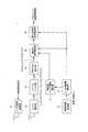
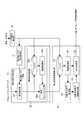
図2は、本実施の形態1に係るレーダ装置1の構成の一例を示すブロック図である。レーダ装置1は、車両等の移動体に搭載され、周辺の物体を検出する。レーダ装置1は、レーダ信号送信部11、レンジ測定部12、ドップラフィルタ部13、到来方向推定部14、車両情報取得部15、レーダ移動量算出部16、静止物ドップラ領域算出部17、静止物境界検出部18および静止物境界変動検出部19を有する。以下、各構成について、図面を参照しながら説明する。(Embodiment 1)
FIG. 2 is a block diagram showing an example of the configuration of the
レーダ信号送信部11は、測定開始信号が入力されるとセンシングを行うためのレーダ信号を送信する。レーダ信号送信部11は、1つ以上の送信アンテナを介して、レーダ信号を送信する。 The radar
レンジ測定部12は、レーダ信号が目標物で反射したエコー信号を、1つ以上の受信アンテナを介して受信し、受信信号処理を行う。そして、レンジ測定部12は、レーダ信号の送信からエコー信号の受信までの遅延時間を用いて目標物までのレンジ(距離)を示すレンジプロファイルを算出する。 The
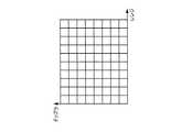
図3Aは、レンジプロファイルの一例を示す図である。図3Aの横軸は、レンジを示している。レンジプロファイルは、受信信号処理後のエコー信号の各レンジにおける反射強度をIQ成分(つまり、複素数)で示している。つまり、図3Aにおける各レンジのグリッドには、複素数の値が含まれている。レンジ測定部12は、図3Aに示すレンジプロファイルを算出し、ドップラフィルタ部13へ出力する。 FIG. 3A is a diagram illustrating an example of a range profile. The horizontal axis in FIG. 3A indicates the range. The range profile indicates the reflection intensity in each range of the echo signal after reception signal processing as an IQ component (that is, a complex number). In other words, each range grid in FIG. 3A includes complex values. The
ドップラフィルタ部13は、レンジ測定部12から取得するレンジプロファイルを時系列に蓄積する。ドップラフィルタ部13は、蓄積したレンジプロファイルの各レンジビン(同一レンジの時系列)におけるプロファイルデータをフーリエ変換し、ドップラ周波数の解析を行い、[レンジ,ドップラ]マップを生成する。 The
図3Bは、時系列に蓄積されたレンジプロファイルの一例を示す図である。図3Bの横軸はレンジを示し、縦軸は時間を示している。図3Cは、[レンジ,ドップラ]マップの一例を示す図である。図3Cの横軸はレンジを示し、縦軸はドップラ速度を示している。 FIG. 3B is a diagram illustrating an example of a range profile accumulated in time series. The horizontal axis in FIG. 3B indicates the range, and the vertical axis indicates time. FIG. 3C is a diagram illustrating an example of a [range, Doppler] map. In FIG. 3C, the horizontal axis indicates the range, and the vertical axis indicates the Doppler speed.
ドップラフィルタ部13は、図3Bに示す、時系列に蓄積されたレンジプロファイルの各レンジビンにおけるプロファイルデータをフーリエ変換し、各レンジのドップラ周波数を算出する。そして、ドップラフィルタ部13は、算出したドップラ周波数をドップラ速度に変換する。具体的には、レーダ信号の波長をλ、ドップラ周波数をfdとすると、ドップラ速度vdは次式(1)を用いて算出される。
vd=−λ×fd/2 (1)
目標物が相対的にレーダ装置1から遠ざかる方向である場合、ドップラ速度vdは正となる。目標物が相対的にレーダ装置1に近づく方向である場合、ドップラ速度vdは負となる。The
vd = −λ × fd / 2 (1)
When the target is in a direction relatively away from the
ドップラフィルタ部13は、ドップラ周波数をドップラ速度に変換し、図3Cに示す[レンジ,ドップラ]マップを生成する。[レンジ,ドップラ]マップとは、横軸をレンジ、縦軸をドップラ速度とし、各レンジビンにおけるドップラ速度の空間スペクトラムを示したマップである。ドップラフィルタ部13は、[レンジ,ドップラ]マップを到来方向推定部14へ出力する。 The
レンジ測定部12、ドップラフィルタ部13は、1つ以上の受信アンテナから得られる受信信号それぞれに対して処理を実施し、受信アンテナ毎の[レンジ,ドップラ]マップを出力する。 The
到来方向推定部14は、ドップラフィルタ部13から取得する受信アンテナ毎の[レンジ,ドップラ]マップの各[レンジ、ドップラ]ビンにおけるIQ(In-phase Quadrature)データを用いて、所定の到来方向推定アルゴリズムによって、受信したエコー信号の到来方向を推定する。なお、到来方向推定アルゴリズムとしては、例えば、ビームフォーマ法、Capon法、または、MUSIC法などが用いられる。そして、到来方向推定部14は、[方位,レンジ,ドップラ]マップを生成する。上記アルゴリズムでは、受信アンテナ毎の[レンジ、ドップラ]ビンにおけるIQデータの位相差などを用いて到来方向を推定する。 The arrival
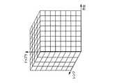
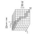
図3Dは、[方位,レンジ,ドップラ]マップの一例を示す図である。図3Dにおける3つの軸は、それぞれ、方位、レンジ、ドップラ速度を示している。到来方向推定部14は、図3Cに示した[レンジ,ドップラ]マップの各[レンジ、ドップラ]ビンにおけるデータから、到来方向(つまり、レーダ装置1における方位方向)を推定し、図3Dに示す[方位,レンジ,ドップラ]マップを生成する。つまり、[方位,レンジ,ドップラ]マップとは、各[方位,レンジ,ドップラ]ビンにおける電力(空間スペクトラム)を示したマップである。到来方向推定部14は、[方位,レンジ,ドップラ]マップを静止物境界検出部18へ出力する。 FIG. 3D is a diagram illustrating an example of an [azimuth, range, Doppler] map. The three axes in FIG. 3D indicate azimuth, range, and Doppler velocity, respectively. The arrival
レンジ測定部12、ドップラフィルタ部13、および、到来方向推定部14は、受信したエコー信号を解析し、方位毎、レンジ毎、および、ドップラ速度毎の反射強度を示す空間スペクトラムのデータを生成する受信信号解析部として機能する。 The
車両情報取得部15は、車両に搭載された図示しない各種センサから、車速、蛇角、旋回速度等の車両の移動量に関する車両情報を取得し、レーダ移動量算出部16へ出力する。 The vehicle
レーダ移動量算出部16は、車両情報取得部15から取得する車両情報と、既知のレーダ装置1の設置位置の情報とを用いて、レーダ装置1の移動速度を示すレーダ速度ベクトルを算出する。レーダ移動量算出部16は、算出したレーダ速度ベクトルを静止物ドップラ領域算出部17へ出力する。 The radar movement
静止物ドップラ領域算出部17は、レーダ移動量算出部16から取得したレーダ速度ベクトルから、レンジ方向の速度成分を算出する。 The stationary object Doppler
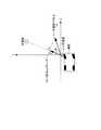
具体的に、静止物ドップラ領域算出部17における静止物ドップラ領域算出処理について、図4A〜図4Cを参照して説明する。図4Aは、静止している目標物と車両との位置関係の一例を示す図である。図4Bは、静止物ドップラ領域の第1の例を示す図である。図4Cは、静止物ドップラ領域の第2の例を示す図である。 Specifically, the stationary object Doppler region calculation processing in the stationary object Doppler
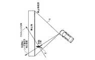
図4Aには、車両と、車両に搭載されたレーダ装置1と、レーダ装置1の検知範囲内の目標物とが示される。図4Aに示すx軸は、レーダ装置1の正面方向を示し、y軸はx軸に垂直な軸である。図4Aに示すx―y平面は、車両が走行する路面に略平行な平面である。また、レーダ移動量算出部16により算出されたレーダ速度ベクトルVsと、目標物に対するレンジ方向の速度成分Vsrが示されている。 FIG. 4A shows a vehicle, a
なお、図4Aにおける目標物は、静止している物体である。 Note that the target in FIG. 4A is a stationary object.
速度ベクトルVsとx軸とのなす角度をθsとし、レーダ装置1と目標物とを結ぶ直線(つまり、目標物に対するレンジ方向)とx軸とのなす角度をθとし、レーダ装置1から遠ざかる方向を正とすると、速度成分Vsrは、次式(2)により算出される。
Vsr=|Vs|×cos(θs−θ) (2)The angle between the velocity vector Vs and the x axis is θs, the angle between the straight line connecting the
Vsr = | Vs | × cos (θs−θ) (2)
そして、目標物のドップラ速度に相当する速度成分Vtの大きさは、次式(3)により算出される。
Vt=−Vsr=−|Vs|×cos(θs−θ) (3)Then, the magnitude of the speed component Vt corresponding to the Doppler speed of the target is calculated by the following equation (3).
Vt = −Vsr = − | Vs | × cos (θs−θ) (3)
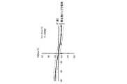
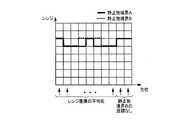
図4Bは、式(3)において、|Vs|=40[km/h]、θs=70[度]とした場合の速度成分Vtをプロットした図である。図4Bにおける横軸は式(3)におけるθ、つまり、目標物が存在する方位であり、縦軸はレーダ装置1から遠ざかる方向を正とした場合の速度成分Vtである。 FIG. 4B is a diagram in which velocity component Vt is plotted when | Vs | = 40 [km / h] and θs = 70 [degrees] in Equation (3). The horizontal axis in FIG. 4B is θ in the equation (3), that is, the direction in which the target exists, and the vertical axis is the velocity component Vt when the direction away from the
静止物ドップラ領域算出部17は、速度ベクトルVsと式(3)とに基づき、速度成分Vtをθ毎に算出する。そして、静止物ドップラ領域算出部17は、算出した速度成分Vtに含まれる誤差を考慮した所定のマージンを与えた領域(図4Bにおいて、点線で挟まれた領域)を静止物ドップラ領域として算出する。例えば、図4Bでは、速度成分Vtに対して、上方マージンを5[km/h]、下方マージンを−5[km/h]とした静止物ドップラ領域が示されている。なお、上方マージン、下方マージンは、例えば、速度ベクトルに応じて、適宜、設定することができる。 The stationary object Doppler
なお、レーダ装置1は車両に搭載されているため、レーダ速度ベクトルは時々刻々と変化する。そのため、静止物ドップラ領域算出部17が算出する静止物ドップラ領域も、レーダ速度ベクトルの変化に応じて、時々刻々と変化する。図4Cには、静止物ドップラ領域の変化の一例が示される。 Since the
図4Cは、式(3)において、|Vs|=10[km/h]、θs=90[度]とした場合の速度成分Vtをプロットした図である。図4Cにおける横軸は式(3)におけるθ、つまり、目標物が存在する方位であり、縦軸は目標物が存在する方向を正とした場合の速度成分Vtである。また、図4Cには、上方マージンを5[km/h]、下方マージンを−5[km/h]とした静止物ドップラ領域が示されている。 FIG. 4C is a plot of velocity component Vt when | Vs | = 10 [km / h] and θs = 90 [degrees] in Equation (3). The horizontal axis in FIG. 4C is θ in the equation (3), that is, the azimuth in which the target is present, and the vertical axis is the velocity component Vt when the direction in which the target is present is positive. FIG. 4C shows a stationary object Doppler region with an upper margin of 5 [km / h] and a lower margin of −5 [km / h].
図4Cと図4Bとに示されるように、静止物ドップラ領域は、レーダ速度ベクトルVsの大きさ(|Vs|)や角度(θs)に応じて変化する。静止物ドップラ領域算出部17は、算出した静止物ドップラ領域を静止物境界検出部18へ出力する。 As shown in FIGS. 4C and 4B, the stationary object Doppler region changes according to the magnitude (| Vs |) and the angle (θs) of the radar velocity vector Vs. The stationary object Doppler
静止物境界検出部18は、エコー信号を用いて、静止物が存在する領域の境界(以下、静止物境界という)を検出する。具体的には、静止物境界検出部18は、到来方向推定部14から取得する[方位,レンジ,ドップラ]マップと静止物ドップラ領域算出部17から取得する静止物ドップラ領域とを用いて、レーダ装置1を基準とした静止物境界を検出する。 The stationary object
静止物境界とは、レーダ装置1の検知範囲内において、静止物と見なされる物体からの反射が検出された点のうち、レーダ装置1に最も近い点を結んだ線である。静止物と見なされる物体からの反射か否かは、ドップラ速度に基づいて判定される。例えば、反射点のドップラ速度が、図4Bや図4Cに示される静止物ドップラ領域に入る反射点は静止物と見なせばよい。 The stationary object boundary is a line connecting points closest to the
静止物境界は、例えば、[方位,レンジ]平面上の複数の座標を結んだ線によって示される。 The stationary object boundary is indicated by a line connecting a plurality of coordinates on the [azimuth, range] plane, for example.
そして、静止物境界検出部18は、誤差による静止物境界の変動を抑制するために、レーダ速度ベクトルを用いて、過去の静止物境界を現在の座標系に変換し、スムージング処理を行う。静止物境界検出部18は、検出した静止物境界を静止物境界変動検出部19へ出力する。 Then, the stationary object
静止物境界変動検出部19は、静止物境界検出部18から取得する静止物境界を用いて、静止物境界の時間変動を検出する。 The stationary object boundary
静止物境界検出部18と静止物境界変動検出部19の詳細については後述するが、その概要について図5A、図5Bを参照して説明する。 Although details of the stationary object
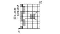
図5A、図5Bは、レーダ装置1を基準とした静止物境界の一例を示す図である。図5A、図5Bには、レーダ装置1の検知範囲R内を移動する目標物Xが、静止物の前を移動する様子が示されている。 5A and 5B are diagrams illustrating an example of a stationary object boundary based on the
図5Aでは、目標物Xはクロスレンジ方向とは異なる方向に移動しており、レーダ装置1は、レーダ装置1を基準としたレンジ方向(目標物とレーダ装置とを結ぶ直線の方向)のドップラ速度成分を観測できる。よって、レーダ装置1で観測される目標物Xのドップラ速度は静止物ドップラ領域外の値となる。そのため、目標物Xは静止物境界から分離されている。 In FIG. 5A, the target X is moving in a direction different from the cross-range direction, and the
一方で、図5Bの場合、目標物Xはクロスレンジ方向に近い方向に移動しているため、目標物Xのドップラ速度は静止物と同等の値が観測される。つまり、目標物Xのドップラ速度は静止物ドップラ領域内の値となる。そのため、目標物Xは静止物と見なされ、目標物Xは静止物境界から分離されない。 On the other hand, in the case of FIG. 5B, since the target X is moving in the direction close to the cross range direction, the Doppler speed of the target X is observed to be equal to that of a stationary object. That is, the Doppler speed of the target X is a value within the stationary object Doppler region. Therefore, the target X is regarded as a stationary object, and the target X is not separated from the stationary object boundary.
なお、レーダ装置1の検知範囲Rのどの位置であっても、クロスレンジ方向に近い方向に移動する目標物Xのドップラ速度は静止物と同等の値が観測される。つまり、図5Aの位置に目標物Xが位置し、クロスレンジ方向に近い方向に移動する場合、目標物Xのドップラ速度は静止物と同等の値が観測される。 Note that, at any position in the detection range R of the
ただし、目標物Xは移動しているため、目標物Xが静止物境界から分離されていない場合であっても、目標物Xの移動に伴って静止物境界が時間に応じて変動する。その際、クロスレンジ方向に移動する、つまり、静止物ドップラ領域内を移動する目標物Xは、図5Bに示すように、静止物境界に凸部として表われる場合が多い。 However, since the target object X is moving, even if the target object X is not separated from the stationary object boundary, the stationary object boundary varies with time as the target object X moves. At that time, the target X that moves in the cross range direction, that is, moves in the stationary object Doppler region, often appears as a convex portion on the stationary object boundary as shown in FIG. 5B.
そのため、本実施の形態1では、静止物境界検出部18が図5A、図5Bに示すような静止物境界を検出し、静止物境界変動検出部19が静止物境界に含まれる凸部の時間変動に基づいて、クロスレンジ方向に移動する、つまり、静止物ドップラ領域内を移動する目標物Xを検出する。 Therefore, in the first embodiment, the stationary object
次に、静止物境界検出部18と静止物境界変動検出部19の詳細について、図6を参照して説明する。 Next, details of the stationary object
図6は、本実施の形態1に係る静止物境界検出部18と静止物境界変動検出部19との構成の一例を示すブロック図である。なお、理解の容易のために、図6には、レーダ移動量算出部16、静止物ドップラ領域算出部17も併せて示されている。 FIG. 6 is a block diagram showing an example of the configuration of the stationary object
静止物境界検出部18は、境界検出部181および境界追従検出部182を有する。 The stationary object
境界検出部181は、到来方向推定部14から取得する[方位,レンジ,ドップラ]マップと静止物ドップラ領域算出部17から取得する静止物ドップラ領域とを用いて、レーダ装置1を基準とした、現在の静止物境界を検出する。 The
図7A、図7Bは、本実施の形態1における静止物境界の検出方法の一例を示す図である。境界検出部181は、図7Aに示すように、[方位,レンジ,ドップラ]マップにおいて、静止物ドップラ領域に対応する領域のデータを、方位軸とレンジ軸とにより規定される[方位,レンジ]平面へ写像する。 7A and 7B are diagrams illustrating an example of a stationary object boundary detection method according to the first embodiment. As shown in FIG. 7A, the
その際、境界検出部181は、1つの方位、1つのレンジにおいて、複数のデータを写像する場合(例えば、図7Aにおける矢印Wの方向への写像)、空間スペクトラムの加算、電力の加算、あるいは、最大値の選択等の方法により、複数のデータから1つのデータを算出し、[方位,レンジ]平面へ写像する。以下では、写像された後の[方位,レンジ]平面上のデータを、[方位,レンジ]マップと呼ぶ。 At that time, the
図7Bは、[方位,レンジ]マップを示している。[方位,レンジ,ドップラ]マップにおける静止物ドップラ領域に対応する領域のデータが、[方位,レンジ]平面に写像されるため、[方位,レンジ]マップに示されるデータのうち所定の閾値よりも大きいデータの座標は、静止物からの反射が検出された点(以下、静止物反射点)に相当する。 FIG. 7B shows an [azimuth, range] map. Since the data of the region corresponding to the stationary object Doppler region in the [azimuth, range, doppler] map is mapped to the [azimuth, range] plane, the data shown in the [azimuth, range] map is more than a predetermined threshold value. Large data coordinates correspond to points where reflection from a stationary object is detected (hereinafter, stationary object reflection points).
境界検出部181は、図7Bに示すように、[方位,レンジ]マップの各方位ビンにおいて、静止物反射点のレンジ座標が最小となる座標を、現在の静止物境界として検出する。 As shown in FIG. 7B, the
なお、周辺静止物(例えば、建物)が存在しないなどの理由により、所定の閾値を超える空間スペクトラム電力が存在しない場合、境界検出部181は、静止物境界のレンジ座標を無限遠として設定する。 Note that when there is no spatial spectrum power exceeding a predetermined threshold due to the absence of a surrounding stationary object (for example, a building), the
また、境界検出部181は、[方位,レンジ]マップを所定の領域に分割し、分割後の領域における静止物反射点が所定数以上である場合に、分割後の領域の境界を現在の静止物境界として検出してもよい。 In addition, the
境界検出部181は、検出した現在の静止物境界を境界追従検出部182へ出力する。 The
境界追従検出部182は、現在の静止物境界と過去の静止物境界とを用いて、スムージング処理を行う。過去の静止物境界とは、レーダ装置1における1回の測定時間を1フレーム、現在フレームをNフレームとすると、現在より所定数Pフレーム前(Pは1以上の整数)のN−PフレームからN−1フレームまでの静止物境界である。具体的に、境界追従検出部182は、バッファ182a、座標変換部182bおよび境界スムージング部182cを有する。 The boundary
バッファ182aには、境界検出部181から取得する現在の静止物境界と、レーダ移動量算出部16から取得する現在のレーダ速度ベクトルとが対応付けて記憶される。バッファ182aには、複数フレームの静止物境界とレーダ速度ベクトルが格納される。 The
座標変換部182bは、バッファ182aに格納された過去の静止物境界と、対応する過去のレーダ速度ベクトルとを読み出し、過去の静止物境界を現在の座標系に変換する。 The coordinate
各フレーム時間間隔が微小な時間(数msec間隔程度)であるため、各フレーム間のレーダ移動速度は一定であると想定できる。つまり、各フレーム間のレーダ装置1の移動量を示すレーダ移動ベクトルは、各フレームにおけるレーダ速度ベクトルに1フレームの時間を乗ずることにより得られる。過去のある時点から現在までのレーダ移動ベクトルは、各フレーム間のレーダ移動ベクトルを加算することで得られる。 Since each frame time interval is a minute time (approximately several msec interval), it can be assumed that the radar moving speed between the frames is constant. That is, the radar movement vector indicating the amount of movement of the
座標変換部182bは、過去のレーダ速度ベクトルからレーダ移動ベクトルを算出し、過去の静止物境界をレーダ移動ベクトルの逆方向にシフトさせる。つまり、座標変換部182bは、過去の静止物境界を、レーダ装置1を基準とした相対的な移動ベクトル(相対移動ベクトル)分シフトさせる。 The coordinate
図8A、図8Bは、座標変換部182bにおける座標変換処理を示す図である。図8Aには、過去の静止物境界と、レーダ移動ベクトルとが示されている。図8Bには、過去の静止物境界と、過去の静止物境界を相対移動ベクトル分シフトさせた現在の静止物境界とが示されている。 8A and 8B are diagrams illustrating coordinate conversion processing in the coordinate
座標変換部182bは、方位、レンジによって示される過去の静止物境界を、レーダ装置1の位置を原点とするx−y座標系に変換する。そして、座標変換部182bは、変換後の静止物境界を相対移動ベクトル分シフトさせ、図8Bに示す現在の静止物境界を得る。座標変換部182bは、x−y座標系によって示される現在の静止物境界を、方位、レンジによって示される座標系に変換する。 The coordinate
座標変換部182bは、方位、レンジによって示される現在の静止物境界を境界スムージング部182cへ出力する。 The coordinate
境界スムージング部182cは、現在の静止物境界を境界検出部181から取得し、過去の静止物境界を変換して得られた現在の静止物境界を座標変換部182bから取得する。そして、境界スムージング部182cは、2つの静止物境界のスムージングを行う。 The
図9は、境界スムージング部182cにおけるスムージング処理の一例を示す図である。図9には、[方位,レンジ]平面上に、境界検出部181から取得した現在の静止物境界Aと、座標変換部182bから取得した現在の静止物境界B(つまり、過去の静止物境界を変換して得られた現在の静止物境界)とが示されている。 FIG. 9 is a diagram illustrating an example of the smoothing process in the
境界スムージング部182cは、スムージング処理として、各方位ビンにおける静止物境界Aのレンジ座標と静止物境界Bのレンジ座標とを平均化する。境界スムージング部182cは、いずれかの静止物境界のレンジ座標が存在しない方位ビンにおいては、存在するレンジ座標の平均化を行う。 The
境界スムージング部182cは、スムージング処理を施した現在の静止物境界を静止物境界変動検出部19へ出力する。 The
静止物境界変動検出部19は、図6に示すように、バッファ191、座標変換部192、凸部方位境界検出部193、凸部方位境界変動算出部194および出力判定部195を有する。 As illustrated in FIG. 6, the stationary object boundary
バッファ191には、境界スムージング部182cから取得する現在の静止物境界と、レーダ移動量算出部16から取得する現在のレーダ速度ベクトルとが対応付けて記憶される。バッファ191には、複数フレームの静止物境界とレーダ速度ベクトルが格納される。 The
座標変換部192は、バッファ191に格納された過去の静止物境界と、対応する過去のレーダ速度ベクトルとを読み出し、過去の静止物境界を現在の座標系に変換する。座標変換部192における座標変換処理は、座標変換部182bの座標変換処理と同様であるので、詳細な説明は省略する。 The coordinate
座標変換部192は、座標変換処理によって、過去の静止物境界を現在の座標系に変換した静止物境界と、現在の静止物境界とを凸部方位境界検出部193へ出力する。 The coordinate
凸部方位境界検出部193は、座標変換部192から取得する現在の境界において、[方位,レンジ]平面のレンジ方向に凸となる方位を検出する。 The convex azimuth
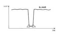
図10は、凸部方位境界検出部193によって検出される凸部の一例を示す図である。凸部方位境界検出部193は、図10に示す点A、Bを、静止物境界における凸となる方位として検出する。 FIG. 10 is a diagram illustrating an example of a convex portion detected by the convex portion azimuth
具体的に、凸部方位境界検出部193は、図10に示す静止物境界の方位軸方向において、各静止物境界のレンジ座標の差分を算出する。そして、凸部方位境界検出部193は、レンジ座標の差分と所定の閾値とを比較し、静止物境界における凸となる方位を検出する。 Specifically, the convex azimuth
図11は、凸部方位境界検出部193における検出処理の一例を示す図である。図11には、図10に示した静止物境界の方位軸方向において、各静止物境界のレンジ座標の差分が示されている。 FIG. 11 is a diagram illustrating an example of detection processing in the convex portion orientation
凸部方位境界検出部193は、図11に示すように、レンジ成分の差分が所定の閾値ThU以上、または、ThL以下となる方位を検出する。図11の場合、ThL以下となる方位が点Aの方位であり、ThU以上となる方位の左隣(方位軸方向で負の方向)の方位が点Bの方位となる。凸部方位境界検出部193は、点A、点Bの方位を凸部の方位として検出し、検出した方位を凸部方位境界変動算出部194へ出力する。As shown in FIG. 11, the convex portion azimuth
凸部方位境界変動算出部194は、凸部方位境界検出部193から取得する凸部の方位を時点毎に凸部方位テーブルに格納する。そして、凸部方位境界変動算出部194は、凸部方位テーブルにおいて、凸部の時間変動によって、静止物境界に含まれる移動物体を判定する。 The convex part azimuth boundary
図12Aは、凸部方位テーブルの一例を示す図である。図12Aの各行は各時点をフレーム番号で示し、各列は方位を示している。凸部方位境界変動算出部194は、凸部を示すマーク(図12Aの場合、AまたはB)をフレーム番号毎に凸部方位テーブルに格納する。 FIG. 12A is a diagram illustrating an example of a convex direction table. Each row in FIG. 12A indicates each time point by a frame number, and each column indicates an orientation. The convex part azimuth boundary
目標物がレーダ装置1の検知範囲内を横切るように移動する場合、目標物の移動方向がクロスレンジ方向となる領域(以下、クロスレンジ領域という)が発生する。その場合、目標物がクロスレンジ領域に進入すると、静止物境界に凸部が発生する。そして、目標物がクロスレンジ領域内を移動すると、発生した凸部が方位方向に移動する。 When the target moves so as to cross the detection range of the
具体的には、凸部方位境界変動算出部194は、凸部方位テーブルにマークが格納された時点を、目標物がクロスレンジ領域に進入した時点として判定する。そして、凸部方位境界変動算出部194は、凸部の時系列での変化を観測することによって、凸部に対応する目標物の移動方向を判定する。 Specifically, the convex part azimuth boundary
図12Aに示す凸部方位テーブルの場合、n−3時点では凸部を示すマークが格納されていないが、n−2時点ではA、Bのマークが格納されている。そして、n−2時点で格納されたA、Bのマークは、n−1時点、n時点において、方位軸方向の正の方向に移動する。 In the case of the convex portion orientation table shown in FIG. 12A, the mark indicating the convex portion is not stored at the time point n-3, but the marks A and B are stored at the time point n-2. The marks A and B stored at time n-2 move in the positive direction of the azimuth axis at time n-1 and time n.
この場合、凸部方位境界変動算出部194は、n−2時点で目標物がクロスレンジ領域に進入したと判定する。また、凸部方位境界変動算出部194は、n−2時点からn時点までの間に、目標物が方位軸方向の正の方向に移動していると判定する。 In this case, the convex portion azimuth boundary
凸部方位境界変動算出部194は、クロスレンジ領域に進入した目標物の方位および移動方向を出力判定部195へ出力する。その際、凸部方位境界変動算出部194は、目標物の方位方向の移動量に基づき目標物の速度を算出し、出力判定部195へ出力してもよい。 The convex part azimuth boundary
なお、凸部方位テーブルには、静止物の形状に起因した凸部が含まれる場合もある。この場合、静止物の形状に起因した凸部のマークは、各時点において同一の方位方向に格納される。凸部方位境界変動算出部194は、凸部の時系列での変化を観測しているため、同一の方位方向に格納される凸部のマークを目標物として判定しない。 In addition, the convex part orientation table may include a convex part due to the shape of the stationary object. In this case, the convex marks resulting from the shape of the stationary object are stored in the same azimuth direction at each time point. Since the convex part azimuth boundary
出力判定部195は、凸部方位境界変動算出部194から取得した目標物の方位および移動方向(および速度)と座標変換部192から取得した現在の静止物境界とを用いて、クロスレンジ移動物標情報を生成する。 The
具体的には、出力判定部195は、現在の静止物境界の[方位,レンジ]平面上の目標物の方位に対応する領域を目標物の現在の位置と判定し、目標物の現在の位置をクロスレンジ移動物標情報として生成する。また、出力判定部195は、クロスレンジ移動物標情報として、目標物の移動方向(および速度)を含めて生成してもよい。 Specifically, the
図12Bは、レーダ装置1が過去において観測した静止物境界の一例を示す図である。なお、図12Bは、目標物が人である例を示している。人は、静止物の前を移動しているが、レーダ装置1を基準として、クロスレンジ方向ではない方向に移動している。このため、人は静止物境界として検出されない。つまり、人は移動物体として検出される。 FIG. 12B is a diagram illustrating an example of a stationary object boundary observed by the
次に、図12Cは、レーダ装置1が現在において観測した静止物境界の一例を示す図である。なお、図12Cは、目標物が人である例を示している。静止物の前を移動する人の移動方向は、レーダ装置1との位置関係が変化したため、レーダ装置1を基準にしてクロスレンジ方向に移動する方向に変化した。このため、レーダ装置1が検出する静止物境界は、人の境界を含む。 Next, FIG. 12C is a diagram illustrating an example of a stationary object boundary currently observed by the
ここで、過去に検出した静止物境界を現在の座標系に変換した静止物境界は、人の境界を含まない。従って、レーダ装置1は、現在の座標系に変換した過去の静止物境界と現在の静止物境界を比較し、検出された凸部がクロスレンジ方向に移動する目標物(図12Cでは人)と判定することができる。 Here, a stationary object boundary obtained by converting a stationary object boundary detected in the past into the current coordinate system does not include a human boundary. Therefore, the
さらに、レーダ装置1は、検出された凸部の方位変動を観測することで、クロスレンジ方向に移動する目標物を追従検出することが可能となる。 Furthermore, the
以上説明したように、本実施の形態1では、静止物ドップラ領域算出部17が、レーダ装置1の速度を用いてレーダ装置1の検知範囲内における静止物のドップラ速度を算出し、静止物境界検出部18が、方位毎、レンジ毎、および、ドップラ速度毎のエコー信号の反射強度を示すマップを取得し、静止物のドップラ速度に対応する反射強度からレーダ装置を基準とした静止物境界を検出する。そして、静止物境界変動算出部19が、静止物境界の時間変化に基づき、静止物境界に含まれる移動物体を算出する。この構成により、クロスレンジ方向に移動する、つまり、静止物ドップラ領域内を移動する目標物のドップラ速度が周辺静止物と同等になってしまっても、目標物を周辺静止物から分離して検出できる。 As described above, in the first embodiment, the stationary object Doppler
(実施の形態2)
実施の形態1では、静止物境界検出部が静止物境界を検出する際に、[方位,レンジ,ドップラ]マップにおける静止物ドップラ領域に対応する領域のデータを、方位軸とレンジ軸とにより規定される[方位,レンジ]平面へ写像する例について説明した。本実施の形態2では、[方位,レンジ,ドップラ]マップにおける静止物ドップラ領域に対応する領域のデータを、方位軸とドップラ軸とにより規定される[方位,ドップラ]平面へ写像する例について説明する。(Embodiment 2)
In the first embodiment, when the stationary object boundary detection unit detects the stationary object boundary, the data of the region corresponding to the stationary object Doppler region in the [azimuth, range, Doppler] map is defined by the azimuth axis and the range axis. An example of mapping to the [azimuth, range] plane is described. In the second embodiment, an example in which data of an area corresponding to a stationary object Doppler area in an [azimuth, range, Doppler] map is mapped to an [azimuth, Doppler] plane defined by the azimuth axis and the Doppler axis will be described. To do.
図13は、本実施の形態2に係る静止物境界検出部28の構成の一例を示すブロック図である。図13において、図2、図6と同様の構成については、同一の符番を付し、説明を省略する。 FIG. 13 is a block diagram illustrating an example of the configuration of the stationary object
本実施の形態2に係るレーダ装置は、図2に示したレーダ装置1において、静止物境界検出部18が、図13に示す静止物境界検出部28に置き換わった構成を有する。 The radar apparatus according to the second embodiment has a configuration in which the stationary object
静止物境界検出部28は、方位ドップラ平面写像部281、クラスタリング部282および境界検出部283を有する。以下、それぞれの構成について、図14A、図14Bを参照して説明する。 The stationary object
図14A、図14Bは、本実施の形態2における静止物境界の検出方法の一例を示す図である。 14A and 14B are diagrams illustrating an example of a stationary object boundary detection method according to the second embodiment.
方位ドップラ平面写像部281は、到来方向推定部14(図2参照)から取得する[方位,レンジ,ドップラ]マップのデータを、図14Aに示すように、方位軸とドップラ軸とにより規定される[方位,ドップラ]平面へ写像する。その際、方位ドップラ平面写像部281は、1つの方位、1つのドップラにおいて、複数のデータを写像する場合、空間スペクトラムの加算、電力の加算、あるいは、最大値の選択、等の方法により、複数のデータから1つのデータを算出し、[方位,ドップラ]平面へ写像する。また、方位ドップラ平面写像部281は、[方位,ドップラ]平面へ写像する際に、写像前のデータの各レンジ成分を写像後のデータに対応付けて保持しておく。以下では、写像された後の[方位,ドップラ]平面上のデータを、[方位,ドップラ]マップと呼ぶ。 The azimuth Doppler
クラスタリング部282は、方位ドップラ平面写像部281から[方位,ドップラ]マップを取得し、静止物ドップラ領域算出部17から静止物ドップラ領域を取得する。そして、クラスタリング部282は、図14Bに示すように、[方位,ドップラ]マップにおける静止物ドップラ領域に対応する領域のデータを抽出し、抽出したデータの内、反射点に対応するレンジ成分が近傍であるか否かを判定し、レンジ座標が近傍である反射点をクラスタリングする。クラスタリングを行うことで複数の反射点を一つの物標にまとめて扱うことができる。 The
クラスタリング部282は、静止物ドップラ領域内で、隣接する反射点のレンジ成分の差分が所定の範囲以下であれば、近傍であると判定すればよい。 The
クラスタリング部282は、クラスタリング処理後の[方位,ドップラ]マップを境界検出部283へ出力する。 The
境界検出部283は、クラスタリング部282から取得するクラスタリング処理後の[方位,ドップラ]マップにおいて、クラスタリングされた反射点の両端の座標の方位成分(図14Bにおける点A、点B)を検出する。そして、境界検出部283は、検出した点A、点Bの方位と、それぞれの方位に対応付けたレンジ成分から、[方位,レンジ]平面のデータを生成する。その結果、境界検出部283は、図10に示した静止物境界と同様の静止物境界を[方位,レンジ]平面のデータとして生成する。 The
境界検出部283は、図10に示した静止物境界と同様の静止物境界を静止物境界変動検出部19へ出力する。 The
以上説明したように、本実施の形態2では、静止物境界検出部28が、方位毎、レンジ毎、および、ドップラ速度毎のエコー信号の反射強度を示すマップを取得し、静止物のドップラ速度に対応するマップの反射強度を、方位軸とドップラ軸とにより規定される[方位,ドップラ]平面に写像することにより、レーダ装置1を基準とした静止物境界を検出する。 As described above, in the second embodiment, the stationary object
[方位,ドップラ]マップにおける静止物ドップラ領域のIQデータを抽出することで、検出対象物を周辺静止物とクロスレンジ方向に移動する、つまり、静止物ドップラ領域内のドップラ速度が観測される移動体に限定することができる。すなわち、レンジ方向のドップラ速度成分を有する移動体を検出対象から除外できるので、クラスタリング部282におけるクラスタリングが誤る確率を低減することができる。 By extracting IQ data of the stationary object Doppler region in the [azimuth, Doppler] map, the detection target is moved in the cross range direction with the surrounding stationary object, that is, the movement in which the Doppler velocity in the stationary object Doppler region is observed. Can be limited to the body. In other words, since the moving object having the Doppler velocity component in the range direction can be excluded from the detection target, the probability of erroneous clustering in the
本構成のようにクラスタリング後の方位境界の時間変動を検出することで、クロスレンジ方向に移動する目標物のドップラ速度が周辺静止物と同等になってしまっても、目標物を周辺静止物から分離して検出できる。 Even if the Doppler speed of the target moving in the cross-range direction is equal to that of the surrounding stationary object by detecting the time variation of the azimuth boundary after clustering as in this configuration, the target is moved from the surrounding stationary object. It can be detected separately.
(実施の形態3)
本実施の形態3では、クロスレンジ方向に移動する、つまり、静止物ドップラ領域内を移動する目標物と、クロスレンジ方向とは異なる方向に移動する目標物とを検出する例について説明する。(Embodiment 3)
In the third embodiment, an example of detecting a target moving in the cross range direction, that is, a target moving in the stationary object Doppler region and a target moving in a direction different from the cross range direction will be described.
図15は、本実施の形態3に係るレーダ装置3の構成の一例を示すブロック図である。図15において、図2と同様の構成については、同一の符番を付し、説明を省略する。 FIG. 15 is a block diagram showing an example of the configuration of the
本実施の形態3に係るレーダ装置3は、図2に示したレーダ装置1に、移動体検出部31と検出結果結合部32とを追加した構成を有する。 The
移動体検出部31は、到来方向推定部14から取得する[方位,レンジ,ドップラ]マップのデータを、方位軸とドップラ軸とにより規定される[方位,ドップラ]平面へ写像する。 The moving
その際、移動体検出部31は、1つの方位、1つのドップラにおいて、複数のデータを写像する場合、空間スペクトラムの加算、電力の加算、あるいは、最大値の選択、等の方法により、複数のデータから1つのデータを算出し、[方位,ドップラ]平面へ写像する。 At that time, the mobile
また、移動体検出部31は、[方位,ドップラ]平面へ写像する際に、写像前のデータの各レンジ成分を写像後のデータに対応付けて保持しておく。以下では、写像された後の[方位,ドップラ]平面上のデータを、[方位,ドップラ]マップと呼ぶ。 Further, when mapping to the [azimuth, Doppler] plane, the moving
移動体検出部31は、[方位,ドップラ]マップにおいて、レンジ成分が近傍である反射点をクラスタリングする。また、移動体検出部31は、静止物ドップラ領域算出部17から静止物ドップラ領域を取得する。そして、移動体検出部31は、クラスタリング後の[方位,ドップラ]平面において、静止物ドップラ領域外の領域に存在する反射点を検出する。 The moving
前述の通り、静止物ドップラ領域内に存在する反射点は、静止物から反射した点、または、クロスレンジ方向に移動する、つまり、静止物ドップラ領域内のドップラ速度が観測される目標物から反射した点である。移動体検出部31は、静止物ドップラ領域外の領域に存在する反射点を検出することにより、クロスレンジ方向とは異なる方向に移動する目標物を検出できる。 As described above, the reflection point existing in the stationary object Doppler region is reflected from the point reflected from the stationary object or in the cross range direction, that is, reflected from the target where the Doppler velocity in the stationary object Doppler region is observed. This is the point. The moving
移動体検出部31は、検出した目標物の反射点の位置を示す情報を検出結果結合部32へ出力する。 The moving
検出結果結合部32は、移動体検出部31から、クロスレンジ方向とは異なる方向に移動する目標物の位置を示す情報を取得する。検出結果結合部32は、静止物境界変動検出部19から、クロスレンジ方向に移動する、つまり、静止物ドップラ領域内のドップラ速度が観測される目標物の位置を示すクロスレンジ移動物標情報を取得する。そして、検出結果結合部32は、クロスレンジ方向とは異なる方向に移動する目標物の位置と、クロスレンジ方向に移動する目標物の位置とを結合する。 The detection
図16A、図16Bは、検出結果結合部32における結合処理を示す図である。図16Aは、クロスレンジ方向とは異なる方向に移動する目標物Xを示し、図16Bは、クロスレンジ方向に移動する目標物Xを示している。検出結果結合部32は、図16Aに示す目標物Xの位置と図16Bに示す目標物Xの位置とを結合し、レーダ装置3の検知範囲内における目標物Xの位置を示す移動物標情報として出力する。 16A and 16B are diagrams illustrating a combining process in the detection
以上説明したように、本実施の形態3のレーダ装置3は、クロスレンジ方向とは異なる方向に移動する目標物を検出する移動体検出部31、および、クロスレンジ方向とは異なる方向に移動する目標物の位置と、クロスレンジ方向に移動する目標物の位置とを結合して出力する検出結果結合部32を有する。この構成により、レーダ装置の検知範囲内で移動する目標物の検出を途切れること無く行うことができ、検知範囲内の目標物の追従をより効果的に行うことができる。 As described above, the
なお、本実施の形態3では、レーダ装置3が図2に示した静止物境界検出部18を有する例について説明したが、本開示はこれに限定されない。静止物境界検出部18は、図13に示した静止物境界検出部28に置き換えられてもよい。 In the third embodiment, the example in which the
なお、上記の各実施の形態では、3次元の[方位,レンジ,ドップラ]マップを用いて、2次元の平面上に写像を行い、静止物境界を検出する例について説明したが、本開示はこれに限定されない。静止物境界を検出する際に用いられるデータは、方位毎、レンジ毎、および、ドップラ速度毎に対応づけられたエコー信号の反射強度を示すデータであれば、3次元のマップに限定されない。そして、静止物境界検出部は、当該データに含まれる静止物のドップラ速度に対応する反射強度のデータを用いて、静止物境界を算出する。その際、静止物境界検出部は、2次元の平面への写像を行わずに、反射強度の強弱に基づき、静止物境界を算出してもよい。 In each of the above-described embodiments, an example has been described in which a three-dimensional [azimuth, range, Doppler] map is used to perform mapping on a two-dimensional plane to detect a stationary object boundary. It is not limited to this. The data used when detecting the boundary of the stationary object is not limited to a three-dimensional map as long as the data indicates the reflection intensity of the echo signal associated with each azimuth, each range, and each Doppler velocity. Then, the stationary object boundary detection unit calculates the stationary object boundary by using the reflection intensity data corresponding to the Doppler velocity of the stationary object included in the data. At that time, the stationary object boundary detection unit may calculate the stationary object boundary based on the strength of the reflection intensity without mapping to the two-dimensional plane.
以上、図面を参照しながら各種の実施の形態について説明したが、本開示はかかる例に限定されないことは言うまでもない。当業者であれば、特許請求の範囲に記載された範疇内において、各種の変更例または修正例に想到し得ることは明らかであり、それらについても当然に本開示の技術的範囲に属するものと了解される。また、開示の趣旨を逸脱しない範囲において、上記実施の形態における各構成要素を任意に組み合わせてもよい。 While various embodiments have been described above with reference to the drawings, it goes without saying that the present disclosure is not limited to such examples. It will be apparent to those skilled in the art that various changes and modifications can be made within the scope of the claims, and these are naturally within the technical scope of the present disclosure. Understood. In addition, the constituent elements in the above embodiments may be arbitrarily combined within the scope not departing from the spirit of the disclosure.
上記各実施の形態では、本開示はハードウェアを用いて構成する例にとって説明したが、本開示はハードウェアとの連携においてソフトウェアでも実現することも可能である。 In each of the above-described embodiments, the present disclosure has been described for an example configured using hardware. However, the present disclosure can also be realized by software in cooperation with hardware.
また、上記各実施の形態の説明に用いた各機能ブロックは、典型的には、入力端子および出力端子を有する集積回路であるLSIとして実現される。これらは個別に1チップ化されてもよいし、一部または全てを含むように1チップ化されてもよい。ここでは、LSIとしたが、集積度の違いにより、IC、システムLSI、スーパーLSI、ウルトラLSIと呼称されることもある。 In addition, each functional block used in the description of the above embodiments is typically realized as an LSI that is an integrated circuit having an input terminal and an output terminal. These may be individually made into one chip, or may be made into one chip so as to include a part or all of them. The name used here is LSI, but it may also be called IC, system LSI, super LSI, or ultra LSI depending on the degree of integration.
また、集積回路化の手法はLSIに限るものではなく、専用回路または汎用プロセッサを用いて実現してもよい。LSI製造後に、プログラムすることが可能なFPGA(Fieled Programmable Gate Array)、LSI内部の回路セルの接続又は設定を再構成可能なリコンフィギュラブル プロセッサ(Reconfigurable Processor)を利用してもよい。 Further, the method of circuit integration is not limited to LSI's, and implementation using dedicated circuitry or general purpose processors is also possible. A programmable programmable gate array (FPGA) that can be programmed after manufacturing the LSI, or a reconfigurable processor (reconfigurable processor) that can reconfigure the connection or setting of circuit cells inside the LSI may be used.
さらには、半導体技術の進歩又は派生する別技術により,LSIに置き換わる集積回路化の技術が登場すれば、当然、その技術を用いて機能ブロックを集積化してもよい。バイオ技術の適用等が可能性としてありえる。 Furthermore, if integrated circuit technology comes out to replace LSI's as a result of the advancement of semiconductor technology or a derivative other technology, it is naturally also possible to integrate function blocks using this technology. Biotechnology can be applied.
本開示は、車両に搭載されるレーダ装置に有用である。 The present disclosure is useful for a radar device mounted on a vehicle.
1、3 レーダ装置
11 レーダ信号送信部
12 レンジ測定部
13 ドップラフィルタ部
14 到来方向推定部
15 車両情報取得部
16 レーダ移動量算出部
17 静止物ドップラ領域算出部
18、28 静止物境界検出部
19 静止物境界変動検出部
31 移動体検出部
32 検出結果結合部
181、283 境界検出部
182 境界追従検出部
182a、191 バッファ
182b、192 座標変換部
182c 境界スムージング部
193 凸部方位境界検出部
194 凸部方位境界変動算出部
195 出力判定部
281 方位ドップラ平面写像部
282 クラスタリング部DESCRIPTION OF
Claims (8)
Translated fromJapanese物体によって前記レーダ信号が反射されたエコー信号を受信する受信部と、
前記エコー信号を用いて、静止物が存在する領域の境界を検出する静止物境界検出部と、
前記静止物が存在する領域の境界が時間変化する領域を検出し、前記時間変化する領域の移動方向が、前記受信部に対してクロスレンジ方向である場合、前記時間変化する領域を、移動する第1物体として検出する静止物境界変動検出部と、
を備える移動体に設置されたレーダ装置。A transmitter for transmitting radar signals;
A receiver for receiving an echo signal in which the radar signal is reflected by an object;
Using the echo signal, a stationary object boundary detection unit that detects a boundary of a region where a stationary object exists;
A region where the boundary of the region where the stationary object exists is detected is time-varying, and when the moving direction of the time-changing region is a cross range direction with respect to the receiving unit, the time-changing region is moved. A stationary object boundary fluctuation detection unit for detecting the first object;
A radar apparatus installed on a moving body.
前記レーダ装置の速度を用いて、前記レーダ装置の方位、レンジにより規定される検知範囲内における静止物のドップラ速度を算出する静止物ドップラ領域算出部と、
前記エコー信号を解析し、前記方位毎、前記レンジ毎、および、前記エコー信号が示すドップラ速度毎に対応づけられた前記エコー信号の反射強度を示すIQデータを生成する受信信号解析部と、
を更に備え、
前記静止物境界検出部は、前記IQデータの中で前記静止物のドップラ速度に対応する反射強度を用いて前記静止物が存在する領域の境界を検出する、
請求項1に記載のレーダ装置。A radar movement amount calculation unit for calculating the speed of the radar device using information indicating the movement amount of the moving body;
A stationary object Doppler region calculating unit that calculates a Doppler velocity of a stationary object within a detection range defined by the azimuth and range of the radar apparatus, using the speed of the radar apparatus;
A reception signal analysis unit that analyzes the echo signal and generates IQ data indicating the reflection intensity of the echo signal associated with each azimuth, each range, and each Doppler velocity indicated by the echo signal;
Further comprising
The stationary object boundary detection unit detects a boundary of an area where the stationary object exists using a reflection intensity corresponding to the Doppler velocity of the stationary object in the IQ data.
The radar apparatus according to claim 1.
前記静止物境界検出部は、前記3次元のマップから前記レンジを示す軸と前記方位を示す軸とにより規定される2次元平面へ前記静止物のドップラ速度に対応する前記反射強度を写像し、前記2次元平面上の反射強度が示す境界を前記静止物が存在する領域の境界として検出する、
請求項2に記載のレーダ装置。The IQ data is a three-dimensional map defined by an axis indicating the azimuth, an axis indicating the range, and an axis indicating the Doppler velocity.
The stationary object boundary detection unit maps the reflection intensity corresponding to the Doppler velocity of the stationary object to a two-dimensional plane defined by the axis indicating the range and the axis indicating the azimuth from the three-dimensional map, Detecting a boundary indicated by a reflection intensity on the two-dimensional plane as a boundary of an area where the stationary object exists;
The radar apparatus according to claim 2.
請求項3に記載のレーダ装置。The stationary object boundary detection unit performs a smoothing process between a boundary of a region where a current stationary object exists and a boundary obtained by converting a boundary of a region where a past stationary object exists into a current coordinate system. Output the later boundary to the stationary object boundary fluctuation detection unit as the boundary of the region where the stationary object exists,
The radar apparatus according to claim 3.
前記静止物境界検出部は、前記3次元のマップから、前記方位を示す軸と前記ドップラ速度を示す軸とにより規定される2次元平面へ、前記静止物のドップラ速度に対応する前記反射強度を写像し、前記2次元平面上の反射強度が示す境界を前記静止物が存在する領域の境界として検出する、
請求項2に記載のレーダ装置。The IQ data is a three-dimensional map defined by an axis indicating the azimuth, an axis indicating the range, and an axis indicating the Doppler velocity.
The stationary object boundary detection unit converts the reflection intensity corresponding to the Doppler velocity of the stationary object from the three-dimensional map to a two-dimensional plane defined by the axis indicating the azimuth and the axis indicating the Doppler velocity. Mapping, and detecting the boundary indicated by the reflection intensity on the two-dimensional plane as the boundary of the region where the stationary object exists,
The radar apparatus according to claim 2.
請求項1から5のいずれか一項に記載のレーダ装置。The stationary object boundary fluctuation detection unit detects the convex part as the first object when a convex part included in a boundary of a region where the stationary object exists moves with a change in time.
The radar apparatus according to any one of claims 1 to 5.
前記第1物体の位置情報と、前記第2物体の位置情報とを、統合して出力する検出結果結合部と、
を更に備える、
請求項2から6のいずれか一項に記載のレーダ装置。A moving body detection unit that detects a second object that moves in a direction different from the cross range direction based on a reflection intensity corresponding to a Doppler speed different from the Doppler speed of the stationary object in the IQ data;
A detection result combining unit that outputs the position information of the first object and the position information of the second object in an integrated manner;
Further comprising
The radar device according to any one of claims 2 to 6.
物体によって前記レーダ信号が反射されたエコー信号を受信し、
前記エコー信号を用いて、静止物が存在する領域の境界を検出し、
前記静止物が存在する領域の境界が時間変化する領域を検出し、
前記時間変化する領域の移動方向が、受信部に対してクロスレンジ方向である場合、前記時間変化する領域を、移動する第1物体として検出する、
移動体に設置されたレーダ装置における検出方法。Send radar signals,
Receiving an echo signal in which the radar signal is reflected by an object;
Using the echo signal, detect the boundary of the area where the stationary object exists,
Detecting a region where the boundary of the region where the stationary object exists changes over time;
When the moving direction of the time-varying region is a cross range direction with respect to the receiving unit, the time-changing region is detected as a moving first object.
A detection method in a radar apparatus installed on a moving body.
Priority Applications (3)
| Application Number | Priority Date | Filing Date | Title |
|---|---|---|---|
| JP2016117102AJP2017223461A (en) | 2016-06-13 | 2016-06-13 | Radar device and detection method |
| CN201710366128.3ACN107490793A (en) | 2016-06-13 | 2017-05-22 | Radar installations and detection method |
| US15/612,855US20170356991A1 (en) | 2016-06-13 | 2017-06-02 | Radar device and detection method |
Applications Claiming Priority (1)
| Application Number | Priority Date | Filing Date | Title |
|---|---|---|---|
| JP2016117102AJP2017223461A (en) | 2016-06-13 | 2016-06-13 | Radar device and detection method |
Publications (1)
| Publication Number | Publication Date |
|---|---|
| JP2017223461Atrue JP2017223461A (en) | 2017-12-21 |
Family
ID=60572633
Family Applications (1)
| Application Number | Title | Priority Date | Filing Date |
|---|---|---|---|
| JP2016117102ACeasedJP2017223461A (en) | 2016-06-13 | 2016-06-13 | Radar device and detection method |
Country Status (3)
| Country | Link |
|---|---|
| US (1) | US20170356991A1 (en) |
| JP (1) | JP2017223461A (en) |
| CN (1) | CN107490793A (en) |
Cited By (1)
| Publication number | Priority date | Publication date | Assignee | Title |
|---|---|---|---|---|
| WO2021241045A1 (en)* | 2020-05-25 | 2021-12-02 | ソニーセミコンダクタソリューションズ株式会社 | Signal processing device, signal processing method, and program |
Families Citing this family (27)
| Publication number | Priority date | Publication date | Assignee | Title |
|---|---|---|---|---|
| JP6924066B2 (en)* | 2017-04-27 | 2021-08-25 | 株式会社デンソーテン | Radar device and target detection method |
| US10528057B2 (en)* | 2017-09-25 | 2020-01-07 | GM Global Technology Operations LLC | Systems and methods for radar localization in autonomous vehicles |
| DE102018200755A1 (en)* | 2018-01-18 | 2019-07-18 | Robert Bosch Gmbh | Method and device for plausibility of a transverse movement |
| JP6847885B2 (en)* | 2018-03-20 | 2021-03-24 | 株式会社東芝 | Information processing equipment, information processing methods and programs |
| EP3553551B1 (en) | 2018-04-10 | 2022-06-01 | Aptiv Technologies Limited | Method for the recognition of an object |
| EP3553559B1 (en)* | 2018-04-11 | 2022-06-01 | Aptiv Technologies Limited | Method for the recognition of objects |
| EP3553552B1 (en) | 2018-04-11 | 2022-05-25 | Aptiv Technologies Limited | Method for the recognition of a moving pedestrian |
| WO2019220503A1 (en)* | 2018-05-14 | 2019-11-21 | 三菱電機株式会社 | Object detection device and object detection method |
| CN109001718A (en)* | 2018-06-22 | 2018-12-14 | 安徽尼古拉电子科技有限公司 | A kind of radar range finding method based on doppler principle |
| KR102628655B1 (en)* | 2018-06-29 | 2024-01-24 | 삼성전자주식회사 | Method and device to operate radar |
| CN109379707B (en)* | 2018-08-31 | 2020-09-01 | 北京大学(天津滨海)新一代信息技术研究院 | Indoor target activity area identification method and system based on wireless signals |
| US11125869B2 (en)* | 2018-10-16 | 2021-09-21 | Infineon Technologies Ag | Estimating angle of human target using mmWave radar |
| CN111722196A (en)* | 2019-03-19 | 2020-09-29 | 富士通株式会社 | Radar reflection point extraction method and device |
| CN111699407B (en)* | 2019-03-29 | 2024-08-02 | 深圳市卓驭科技有限公司 | Method for detecting stationary object near fence by microwave radar and millimeter wave radar |
| JP7323356B2 (en)* | 2019-06-28 | 2023-08-08 | フォルシアクラリオン・エレクトロニクス株式会社 | PARKING ASSIST DEVICE AND PARKING ASSIST METHOD |
| WO2021111600A1 (en)* | 2019-12-05 | 2021-06-10 | 三菱電機株式会社 | Radar signal processing device, radar sensor system, and signal processing method |
| CN111239702B (en)* | 2019-12-30 | 2022-03-01 | 北京润科通用技术有限公司 | Method and device for determining motion state of target object |
| CN113204234B (en)* | 2020-01-15 | 2023-08-22 | 宏碁股份有限公司 | Vehicle control method and vehicle control system |
| US11740327B2 (en)* | 2020-05-27 | 2023-08-29 | Qualcomm Incorporated | High resolution and computationally efficient radar techniques |
| JP7163342B2 (en) | 2020-06-29 | 2022-10-31 | 京セラ株式会社 | ELECTRONIC DEVICE, ELECTRONIC DEVICE CONTROL METHOD, AND PROGRAM |
| CN112083402B (en)* | 2020-09-15 | 2022-12-13 | 哈尔滨工程大学 | An experimental method for underwater target navigating detection under the condition of water pool |
| JP7205009B2 (en)* | 2020-10-06 | 2023-01-16 | 三菱電機株式会社 | OBJECT DETECTION DEVICE, RADAR DEVICE AND OBJECT DETECTION METHOD |
| US11802939B2 (en)* | 2020-11-16 | 2023-10-31 | Samsung Electronics Co., Ltd. | Method and apparatus with radar signal processing |
| CN112526500B (en)* | 2020-11-20 | 2024-06-07 | 广州极飞科技股份有限公司 | Radar detection data processing method and related device |
| CN112526503B (en)* | 2020-11-20 | 2024-06-07 | 广州极飞科技股份有限公司 | Method for detecting object distance and related device |
| WO2022139843A1 (en) | 2020-12-24 | 2022-06-30 | Intel Corporation | Radar apparatus, system, and method |
| EP4194885B1 (en)* | 2021-12-09 | 2025-10-15 | Aptiv Technologies AG | Method for determining the mobility status of a target object |
Citations (13)
| Publication number | Priority date | Publication date | Assignee | Title |
|---|---|---|---|---|
| JP2003194926A (en)* | 2001-12-21 | 2003-07-09 | Mitsubishi Electric Corp | Equipment and method for processing radar signal |
| JP2011085476A (en)* | 2009-10-15 | 2011-04-28 | Honda Motor Co Ltd | Object detector |
| WO2011078264A1 (en)* | 2009-12-25 | 2011-06-30 | 本田技研工業株式会社 | Image processing apparatus, image processing method, computer program, and mobile body |
| JP2011247721A (en)* | 2010-05-26 | 2011-12-08 | Mitsubishi Electric Corp | Angular velocity estimation device, computer program, and angular velocity estimation method |
| JP2013234956A (en)* | 2012-05-10 | 2013-11-21 | Sanyo Electric Co Ltd | Information acquisition apparatus and object detection system |
| JP2014035302A (en)* | 2012-08-09 | 2014-02-24 | Panasonic Corp | Object detection device, object detection method and program |
| JP2014174275A (en)* | 2013-03-07 | 2014-09-22 | Advanced Telecommunication Research Institute International | Geographical map preparation device, geographical map preparation program, and geographical map preparation method |
| US20160084941A1 (en)* | 2014-09-19 | 2016-03-24 | Delphi Technologies, Inc. | Radar system with phase based multi-target detection |
| US20160124087A1 (en)* | 2014-09-05 | 2016-05-05 | GM Global Technology Operations LLC | Object boundary detection for automotive radar imaging |
| JP2016070733A (en)* | 2014-09-29 | 2016-05-09 | パナソニックIpマネジメント株式会社 | Radar device |
| JP2017524898A (en)* | 2014-06-05 | 2017-08-31 | コンティ テミック マイクロエレクトロニック ゲゼルシャフト ミット ベシュレンクテル ハフツングConti Temic microelectronic GmbH | Radar system with optimized storage of intermediate data |
| US20190073901A1 (en)* | 2017-09-06 | 2019-03-07 | Robert Bosch Gmbh | On-street parking map generation |
| US20190107613A1 (en)* | 2017-10-06 | 2019-04-11 | Inxpect S.P.A. | Radar detection methods and systems for identifying moving objects |
Family Cites Families (12)
| Publication number | Priority date | Publication date | Assignee | Title |
|---|---|---|---|---|
| IT1160079B (en)* | 1977-11-17 | 1987-03-04 | Nec Corp | RADAR FOR INDICATION OF MOVING OBJECTS |
| JP4899599B2 (en)* | 2006-04-07 | 2012-03-21 | マツダ株式会社 | Vehicle obstacle detection device |
| JP4407665B2 (en)* | 2006-04-18 | 2010-02-03 | 株式会社豊田中央研究所 | Object detection device |
| AU2010257107B2 (en)* | 2009-02-20 | 2015-07-09 | Digital Signal Corporation | System and method for generating three dimensional images using lidar and video measurements |
| JP5424959B2 (en)* | 2010-03-31 | 2014-02-26 | 富士通テン株式会社 | Signal processing device, radar device, vehicle control system, and signal processing method |
| JP5535816B2 (en)* | 2010-08-04 | 2014-07-02 | 株式会社豊田中央研究所 | Moving object prediction apparatus and program |
| US20140071121A1 (en)* | 2012-09-11 | 2014-03-13 | Digital Signal Corporation | System and Method for Off Angle Three-Dimensional Face Standardization for Robust Performance |
| JP2015025742A (en)* | 2013-07-26 | 2015-02-05 | トヨタ自動車株式会社 | Foreign object detection device |
| WO2015037173A1 (en)* | 2013-09-12 | 2015-03-19 | パナソニック株式会社 | Radar device, vehicle, and moving-body-speed detection method |
| JP6370607B2 (en)* | 2014-05-27 | 2018-08-08 | 住友電気工業株式会社 | Radio wave sensor, detection method and detection program |
| JP2016103194A (en)* | 2014-11-28 | 2016-06-02 | パナソニックIpマネジメント株式会社 | Vehicle travel support system and vehicle travel support method |
| SE1551370A1 (en)* | 2015-10-22 | 2017-02-07 | Uniquesec Ab | Testing method with virtual radar signatures for an automotive safety radar system |
- 2016
- 2016-06-13JPJP2016117102Apatent/JP2017223461A/ennot_activeCeased
- 2017
- 2017-05-22CNCN201710366128.3Apatent/CN107490793A/enactivePending
- 2017-06-02USUS15/612,855patent/US20170356991A1/ennot_activeAbandoned
Patent Citations (13)
| Publication number | Priority date | Publication date | Assignee | Title |
|---|---|---|---|---|
| JP2003194926A (en)* | 2001-12-21 | 2003-07-09 | Mitsubishi Electric Corp | Equipment and method for processing radar signal |
| JP2011085476A (en)* | 2009-10-15 | 2011-04-28 | Honda Motor Co Ltd | Object detector |
| WO2011078264A1 (en)* | 2009-12-25 | 2011-06-30 | 本田技研工業株式会社 | Image processing apparatus, image processing method, computer program, and mobile body |
| JP2011247721A (en)* | 2010-05-26 | 2011-12-08 | Mitsubishi Electric Corp | Angular velocity estimation device, computer program, and angular velocity estimation method |
| JP2013234956A (en)* | 2012-05-10 | 2013-11-21 | Sanyo Electric Co Ltd | Information acquisition apparatus and object detection system |
| JP2014035302A (en)* | 2012-08-09 | 2014-02-24 | Panasonic Corp | Object detection device, object detection method and program |
| JP2014174275A (en)* | 2013-03-07 | 2014-09-22 | Advanced Telecommunication Research Institute International | Geographical map preparation device, geographical map preparation program, and geographical map preparation method |
| JP2017524898A (en)* | 2014-06-05 | 2017-08-31 | コンティ テミック マイクロエレクトロニック ゲゼルシャフト ミット ベシュレンクテル ハフツングConti Temic microelectronic GmbH | Radar system with optimized storage of intermediate data |
| US20160124087A1 (en)* | 2014-09-05 | 2016-05-05 | GM Global Technology Operations LLC | Object boundary detection for automotive radar imaging |
| US20160084941A1 (en)* | 2014-09-19 | 2016-03-24 | Delphi Technologies, Inc. | Radar system with phase based multi-target detection |
| JP2016070733A (en)* | 2014-09-29 | 2016-05-09 | パナソニックIpマネジメント株式会社 | Radar device |
| US20190073901A1 (en)* | 2017-09-06 | 2019-03-07 | Robert Bosch Gmbh | On-street parking map generation |
| US20190107613A1 (en)* | 2017-10-06 | 2019-04-11 | Inxpect S.P.A. | Radar detection methods and systems for identifying moving objects |
Non-Patent Citations (1)
| Title |
|---|
| 高木 聖和,外2名: ""レーザレーダによる歩行者認識技術"", デンソーテクニカルレビュー VOL.12 NO.1 DENSO TECHNICAL REVIEW, vol. 第12巻第1号, JPN6019045362, 13 January 2009 (2009-01-13), pages 35 - 39, ISSN: 0004158930* |
Cited By (1)
| Publication number | Priority date | Publication date | Assignee | Title |
|---|---|---|---|---|
| WO2021241045A1 (en)* | 2020-05-25 | 2021-12-02 | ソニーセミコンダクタソリューションズ株式会社 | Signal processing device, signal processing method, and program |
Also Published As
| Publication number | Publication date |
|---|---|
| US20170356991A1 (en) | 2017-12-14 |
| CN107490793A (en) | 2017-12-19 |
Similar Documents
| Publication | Publication Date | Title |
|---|---|---|
| JP2017223461A (en) | Radar device and detection method | |
| US11885872B2 (en) | System and method for camera radar fusion | |
| US20240094368A1 (en) | Systems and methods for virtual aperture radar tracking | |
| US10605896B2 (en) | Radar-installation-angle calculating device, radar apparatus, and radar-installation-angle calculating method | |
| US11828839B2 (en) | Method and apparatus for operating radar | |
| US10267907B2 (en) | Radar apparatus and radar state estimation method | |
| EP3252501B1 (en) | Enhanced object detection and motion state estimation for a vehicle environment detection system | |
| Jiménez et al. | Improving the obstacle detection and identification algorithms of a laserscanner-based collision avoidance system | |
| US11506745B2 (en) | Vehicular self-positioning | |
| US20160161609A1 (en) | Object detection device, velocity detection device, and vehicle | |
| JP2017067756A (en) | Object detection apparatus and object detection method | |
| JP5425039B2 (en) | Satellite signal determination apparatus and program | |
| JP5184196B2 (en) | Radar apparatus, radar apparatus signal processing method, and vehicle control system | |
| WO2020095819A1 (en) | Object detecting device | |
| WO2016031918A1 (en) | Axial displacement diagnosis apparatus | |
| KR101938898B1 (en) | Method and device for detecting a beam of radar array antenna | |
| JP2018151327A (en) | Radar device and method of combining bearings | |
| KR20230011696A (en) | Apparatus and method for detecting target using radar | |
| JPH07128440A (en) | Radar equipment | |
| KR20180007827A (en) | System and method for obtaining information of underwater target | |
| JP7647189B2 (en) | Object position detection device and method | |
| JP2023122997A (en) | Information processing device, information processing method and program | |
| WO2024176966A1 (en) | Axial deviation estimating device |
Legal Events
| Date | Code | Title | Description |
|---|---|---|---|
| A621 | Written request for application examination | Free format text:JAPANESE INTERMEDIATE CODE: A621 Effective date:20181219 | |
| RD02 | Notification of acceptance of power of attorney | Free format text:JAPANESE INTERMEDIATE CODE: A7422 Effective date:20190625 | |
| RD04 | Notification of resignation of power of attorney | Free format text:JAPANESE INTERMEDIATE CODE: A7424 Effective date:20191018 | |
| A977 | Report on retrieval | Free format text:JAPANESE INTERMEDIATE CODE: A971007 Effective date:20191114 | |
| A131 | Notification of reasons for refusal | Free format text:JAPANESE INTERMEDIATE CODE: A131 Effective date:20191126 | |
| A521 | Request for written amendment filed | Free format text:JAPANESE INTERMEDIATE CODE: A523 Effective date:20200124 | |
| A01 | Written decision to grant a patent or to grant a registration (utility model) | Free format text:JAPANESE INTERMEDIATE CODE: A01 Effective date:20200310 | |
| A045 | Written measure of dismissal of application [lapsed due to lack of payment] | Free format text:JAPANESE INTERMEDIATE CODE: A045 Effective date:20200804 |