JP2017221418A - Optical measurement system for eyeball - Google Patents
Optical measurement system for eyeballDownload PDFInfo
- Publication number
- JP2017221418A JP2017221418AJP2016119015AJP2016119015AJP2017221418AJP 2017221418 AJP2017221418 AJP 2017221418AJP 2016119015 AJP2016119015 AJP 2016119015AJP 2016119015 AJP2016119015 AJP 2016119015AJP 2017221418 AJP2017221418 AJP 2017221418A
- Authority
- JP
- Japan
- Prior art keywords
- light
- eyeball
- mirror
- optical
- optical path
- Prior art date
- Legal status (The legal status is an assumption and is not a legal conclusion. Google has not performed a legal analysis and makes no representation as to the accuracy of the status listed.)
- Granted
Links
- 230000003287optical effectEffects0.000titleclaimsabstractdescription269
- 210000005252bulbus oculiAnatomy0.000titleclaimsabstractdescription139
- 238000005259measurementMethods0.000titleclaimsabstractdescription79
- 210000002159anterior chamberAnatomy0.000claimsabstractdescription86
- 230000010287polarizationEffects0.000claimsdescription33
- 239000007788liquidSubstances0.000claimsdescription16
- 210000001508eyeAnatomy0.000abstractdescription8
- 210000001742aqueous humorAnatomy0.000description47
- WQZGKKKJIJFFOK-GASJEMHNSA-NGlucoseNatural productsOC[C@H]1OC(O)[C@H](O)[C@@H](O)[C@@H]1OWQZGKKKJIJFFOK-GASJEMHNSA-N0.000description32
- 239000008103glucoseSubstances0.000description32
- 239000013543active substanceSubstances0.000description28
- 210000000695crystalline lenAnatomy0.000description25
- 239000008280bloodSubstances0.000description24
- 210000004369bloodAnatomy0.000description23
- 210000004087corneaAnatomy0.000description20
- 238000000034methodMethods0.000description15
- 238000001514detection methodMethods0.000description10
- 238000007654immersionMethods0.000description8
- 238000010586diagramMethods0.000description7
- 239000000126substanceSubstances0.000description7
- 210000001525retinaAnatomy0.000description6
- 210000000744eyelidAnatomy0.000description5
- 238000000691measurement methodMethods0.000description5
- CIWBSHSKHKDKBQ-JLAZNSOCSA-NAscorbic acidChemical compoundOC[C@H](O)[C@H]1OC(=O)C(O)=C1OCIWBSHSKHKDKBQ-JLAZNSOCSA-N0.000description4
- NOESYZHRGYRDHS-UHFFFAOYSA-NinsulinChemical compoundN1C(=O)C(NC(=O)C(CCC(N)=O)NC(=O)C(CCC(O)=O)NC(=O)C(C(C)C)NC(=O)C(NC(=O)CN)C(C)CC)CSSCC(C(NC(CO)C(=O)NC(CC(C)C)C(=O)NC(CC=2C=CC(O)=CC=2)C(=O)NC(CCC(N)=O)C(=O)NC(CC(C)C)C(=O)NC(CCC(O)=O)C(=O)NC(CC(N)=O)C(=O)NC(CC=2C=CC(O)=CC=2)C(=O)NC(CSSCC(NC(=O)C(C(C)C)NC(=O)C(CC(C)C)NC(=O)C(CC=2C=CC(O)=CC=2)NC(=O)C(CC(C)C)NC(=O)C(C)NC(=O)C(CCC(O)=O)NC(=O)C(C(C)C)NC(=O)C(CC(C)C)NC(=O)C(CC=2NC=NC=2)NC(=O)C(CO)NC(=O)CNC2=O)C(=O)NCC(=O)NC(CCC(O)=O)C(=O)NC(CCCNC(N)=N)C(=O)NCC(=O)NC(CC=3C=CC=CC=3)C(=O)NC(CC=3C=CC=CC=3)C(=O)NC(CC=3C=CC(O)=CC=3)C(=O)NC(C(C)O)C(=O)N3C(CCC3)C(=O)NC(CCCCN)C(=O)NC(C)C(O)=O)C(=O)NC(CC(N)=O)C(O)=O)=O)NC(=O)C(C(C)CC)NC(=O)C(CO)NC(=O)C(C(C)O)NC(=O)C1CSSCC2NC(=O)C(CC(C)C)NC(=O)C(NC(=O)C(CCC(N)=O)NC(=O)C(CC(N)=O)NC(=O)C(NC(=O)C(N)CC=1C=CC=CC=1)C(C)C)CC1=CN=CN1NOESYZHRGYRDHS-UHFFFAOYSA-N0.000description4
- 210000003786scleraAnatomy0.000description4
- 206010012601diabetes mellitusDiseases0.000description3
- 239000011521glassSubstances0.000description3
- 102000004169proteins and genesHuman genes0.000description3
- 108090000623proteins and genesProteins0.000description3
- 102000004877InsulinHuman genes0.000description2
- 108090001061InsulinProteins0.000description2
- 238000004497NIR spectroscopyMethods0.000description2
- XUIMIQQOPSSXEZ-UHFFFAOYSA-NSiliconChemical compound[Si]XUIMIQQOPSSXEZ-UHFFFAOYSA-N0.000description2
- 238000000149argon plasma sinteringMethods0.000description2
- 229960005070ascorbic acidDrugs0.000description2
- 235000010323ascorbic acidNutrition0.000description2
- 239000011668ascorbic acidSubstances0.000description2
- WQZGKKKJIJFFOK-VFUOTHLCSA-Nbeta-D-glucoseChemical compoundOC[C@H]1O[C@@H](O)[C@H](O)[C@@H](O)[C@@H]1OWQZGKKKJIJFFOK-VFUOTHLCSA-N0.000description2
- 210000004204blood vesselAnatomy0.000description2
- 230000001413cellular effectEffects0.000description2
- 210000003743erythrocyteAnatomy0.000description2
- 229940125396insulinDrugs0.000description2
- 210000000265leukocyteAnatomy0.000description2
- 229910052710siliconInorganic materials0.000description2
- 239000010703siliconSubstances0.000description2
- 230000002123temporal effectEffects0.000description2
- 210000001519tissueAnatomy0.000description2
- YCKRFDGAMUMZLT-UHFFFAOYSA-NFluorine atomChemical compound[F]YCKRFDGAMUMZLT-UHFFFAOYSA-N0.000description1
- 125000002066L-histidyl groupChemical group[H]N1C([H])=NC(C([H])([H])[C@](C(=O)[*])([H])N([H])[H])=C1[H]0.000description1
- 241000283973Oryctolagus cuniculusSpecies0.000description1
- 238000000862absorption spectrumMethods0.000description1
- 150000001413amino acidsChemical class0.000description1
- 238000005452bendingMethods0.000description1
- 230000001427coherent effectEffects0.000description1
- 150000001875compoundsChemical class0.000description1
- 239000012530fluidSubstances0.000description1
- 229910052731fluorineInorganic materials0.000description1
- 239000011737fluorineSubstances0.000description1
- 239000002223garnetSubstances0.000description1
- 238000001626infrared photoacoustic spectroscopyMethods0.000description1
- 239000007924injectionSubstances0.000description1
- 238000002347injectionMethods0.000description1
- 230000031700light absorptionEffects0.000description1
- 235000012054mealsNutrition0.000description1
- 230000002093peripheral effectEffects0.000description1
- 238000004867photoacoustic spectroscopyMethods0.000description1
- 239000002504physiological saline solutionSubstances0.000description1
- 229920003229poly(methyl methacrylate)Polymers0.000description1
- 229920002338polyhydroxyethylmethacrylatePolymers0.000description1
- 239000004926polymethyl methacrylateSubstances0.000description1
- 229920001296polysiloxanePolymers0.000description1
- 210000001747pupilAnatomy0.000description1
- 238000002310reflectometryMethods0.000description1
- 239000011347resinSubstances0.000description1
- 229920005989resinPolymers0.000description1
- 210000002966serumAnatomy0.000description1
- XLYOFNOQVPJJNP-UHFFFAOYSA-NwaterSubstancesOXLYOFNOQVPJJNP-UHFFFAOYSA-N0.000description1
Images


Classifications
- A—HUMAN NECESSITIES
- A61—MEDICAL OR VETERINARY SCIENCE; HYGIENE
- A61B—DIAGNOSIS; SURGERY; IDENTIFICATION
- A61B5/00—Measuring for diagnostic purposes; Identification of persons
- A61B5/145—Measuring characteristics of blood in vivo, e.g. gas concentration or pH-value ; Measuring characteristics of body fluids or tissues, e.g. interstitial fluid or cerebral tissue
- A61B5/1455—Measuring characteristics of blood in vivo, e.g. gas concentration or pH-value ; Measuring characteristics of body fluids or tissues, e.g. interstitial fluid or cerebral tissue using optical sensors, e.g. spectral photometrical oximeters
- A—HUMAN NECESSITIES
- A61—MEDICAL OR VETERINARY SCIENCE; HYGIENE
- A61B—DIAGNOSIS; SURGERY; IDENTIFICATION
- A61B3/00—Apparatus for testing the eyes; Instruments for examining the eyes
- A61B3/10—Objective types, i.e. instruments for examining the eyes independent of the patients' perceptions or reactions
- A—HUMAN NECESSITIES
- A61—MEDICAL OR VETERINARY SCIENCE; HYGIENE
- A61B—DIAGNOSIS; SURGERY; IDENTIFICATION
- A61B3/00—Apparatus for testing the eyes; Instruments for examining the eyes
- A61B3/0075—Apparatus for testing the eyes; Instruments for examining the eyes provided with adjusting devices, e.g. operated by control lever
- A—HUMAN NECESSITIES
- A61—MEDICAL OR VETERINARY SCIENCE; HYGIENE
- A61B—DIAGNOSIS; SURGERY; IDENTIFICATION
- A61B3/00—Apparatus for testing the eyes; Instruments for examining the eyes
- A61B3/10—Objective types, i.e. instruments for examining the eyes independent of the patients' perceptions or reactions
- A61B3/102—Objective types, i.e. instruments for examining the eyes independent of the patients' perceptions or reactions for optical coherence tomography [OCT]
- A—HUMAN NECESSITIES
- A61—MEDICAL OR VETERINARY SCIENCE; HYGIENE
- A61B—DIAGNOSIS; SURGERY; IDENTIFICATION
- A61B3/00—Apparatus for testing the eyes; Instruments for examining the eyes
- A61B3/10—Objective types, i.e. instruments for examining the eyes independent of the patients' perceptions or reactions
- A61B3/117—Objective types, i.e. instruments for examining the eyes independent of the patients' perceptions or reactions for examining the anterior chamber or the anterior chamber angle, e.g. gonioscopes
- A—HUMAN NECESSITIES
- A61—MEDICAL OR VETERINARY SCIENCE; HYGIENE
- A61B—DIAGNOSIS; SURGERY; IDENTIFICATION
- A61B5/00—Measuring for diagnostic purposes; Identification of persons
- A61B5/145—Measuring characteristics of blood in vivo, e.g. gas concentration or pH-value ; Measuring characteristics of body fluids or tissues, e.g. interstitial fluid or cerebral tissue
- A61B5/14532—Measuring characteristics of blood in vivo, e.g. gas concentration or pH-value ; Measuring characteristics of body fluids or tissues, e.g. interstitial fluid or cerebral tissue for measuring glucose, e.g. by tissue impedance measurement
- A—HUMAN NECESSITIES
- A61—MEDICAL OR VETERINARY SCIENCE; HYGIENE
- A61B—DIAGNOSIS; SURGERY; IDENTIFICATION
- A61B3/00—Apparatus for testing the eyes; Instruments for examining the eyes
- A61B3/0016—Operational features thereof
Landscapes
- Health & Medical Sciences (AREA)
- Life Sciences & Earth Sciences (AREA)
- Physics & Mathematics (AREA)
- General Health & Medical Sciences (AREA)
- Public Health (AREA)
- Biophysics (AREA)
- Veterinary Medicine (AREA)
- Engineering & Computer Science (AREA)
- Biomedical Technology (AREA)
- Heart & Thoracic Surgery (AREA)
- Medical Informatics (AREA)
- Molecular Biology (AREA)
- Surgery (AREA)
- Animal Behavior & Ethology (AREA)
- Ophthalmology & Optometry (AREA)
- Optics & Photonics (AREA)
- Pathology (AREA)
- Radiology & Medical Imaging (AREA)
- Nuclear Medicine, Radiotherapy & Molecular Imaging (AREA)
- Emergency Medicine (AREA)
- Spectroscopy & Molecular Physics (AREA)
- Eye Examination Apparatus (AREA)
- Investigating Or Analysing Biological Materials (AREA)
- Measurement Of The Respiration, Hearing Ability, Form, And Blood Characteristics Of Living Organisms (AREA)
Abstract
Description
Translated fromJapanese本発明は、眼球の光計測装置に関する。 The present invention relates to an optical measurement device for an eyeball.
特許文献1には、レーザー光を投光する手段と、投光部と同軸上に配置された受光部と、この光軸と所定の距離離れて光軸に平行に配置された鏡とからなり、この鏡がそのほぼ中央に立てた垂線が投光部と受光部を結ぶ直線とそのほぼ中央で交わる向きに配置される事を特徴とする、眼球の所定の部分に光を通す為に使用される眼球測定位置決め用具が記載されている。
ところで、被計測者の眼球の前眼房を横切るように光を出射し、前眼房を横切って眼球外に出てきた光を受光することで前眼房内の眼房水に関する光計測を行う場合、眼球の前眼房の近傍に出射手段(光出射手段)及び受光手段を位置決めする必要がある。
しかしながら、眼球の前眼房は非常に微小な領域であるとともに、眼球周辺の顔の形状が個人個人により異なるため、出射手段及び受光手段を眼球の前眼房を挟む位置に配置しづらかった。そこで、目尻側又は目頭側に、ミラーなどの反射部材により光路を折り曲げることが考えられる。
この場合であっても、出射手段と被計測者の眼球との相対的な位置関係や、被計測者の角膜形状などの経時変動により、光路がずれて、瞼や強膜による光遮断が生じたり、角膜による屈折角変化によって網膜に到達したりして、光が前眼房を通過しなくなって、測定が困難になる場合があった。By the way, light is emitted so as to cross the anterior chamber of the eyeball of the measurement subject, and light measurement related to the aqueous humor in the anterior chamber is received by receiving light that has crossed the anterior chamber and exited the eyeball. When performing, it is necessary to position the emitting means (light emitting means) and the light receiving means in the vicinity of the anterior chamber of the eyeball.
However, since the anterior chamber of the eyeball is a very small area and the shape of the face around the eyeball varies depending on the individual, it is difficult to place the emitting means and the light receiving means at a position sandwiching the anterior chamber of the eyeball. Therefore, it is conceivable to fold the optical path by a reflecting member such as a mirror on the outer corner of the eye or the upper side of the eye.
Even in this case, the optical path is shifted due to the relative positional relationship between the emitting means and the eyeball of the measurement subject and the corneal shape of the measurement subject, so that the light path is shifted, and the light is blocked by the eyelids or the sclera. In some cases, the light reaches the retina due to a change in the angle of refraction caused by the cornea, and the light does not pass through the anterior chamber of the eye, making measurement difficult.
そこで、本発明では、光反射手段への光の入射位置を切り替える切替手段を備えない場合に比べて、前眼房を横切る光路の確保が容易な眼球の光計測装置を提供することを目的とする。 Accordingly, an object of the present invention is to provide an optical measurement device for an eyeball in which it is easy to secure an optical path crossing the anterior chamber as compared with a case where a switching unit that switches an incident position of light to the light reflecting unit is not provided. To do.
請求項1に記載の発明は、光を、眼球の前眼房を横切る方向に反射させる光反射手段と、前記光が前記前眼房を横切る状態からの移動を抑制するように、前記光反射手段への当該光の入射位置を切り替える切替手段とを備える眼球の光計測装置である。
請求項2に記載の発明は、前記光反射手段は、前記光の入射角が予め定められた角度に設定され、前記切替手段は、前記光を反射させる反射部材と、前記反射部材の前記光に対する反射角を変更する角度変更手段と、前記反射部材が反射した前記光を通過させて前記光反射手段に出射するテレセントリック光学系と、を備えることを特徴とする請求項1に記載の眼球の光計測装置である。
請求項3に記載の発明は、前記光を予め定められた偏光にする偏光制御手段を備えることを特徴とする請求項2に記載の眼球の光計測装置である。
請求項4に記載の発明は、前記偏光制御手段は、前記切替手段における前記テレセントリック光学系と前記光反射手段との間に配置されていることを特徴とする請求項3に記載の眼球の光計測装置である。
請求項5に記載の発明は、前記切替手段において、前記反射部材は、前記光に対する反射角が反射面における一の方向及び当該一の方向に直交する方向において変更しうることを特徴とする請求項2乃至4のいずれか1項に記載の眼球の光計測装置である。
請求項6に記載の発明は、前記光反射手段は、前記光の入射角が予め定められた角度に設定され、前記切替手段は、前記光を反射させる反射部材と、前記反射部材を前記光の進行する前後方向に移動させる移動手段と、を備えることを特徴とする請求項1に記載の眼球の光計測装置である。
請求項7に記載の発明は、前記光を予め定められた偏光にする偏光制御手段を備えることを特徴とする請求項6に記載の眼球の光計測装置である。
請求項8に記載の発明は、前記眼球の前眼房の周囲を液体に浸漬する容器を有することを特徴とする請求項1乃至7のいずれか1項に記載の眼球の光計測装置である。
請求項9に記載の発明は、前記光反射手段が、前記眼球の表面に接触して用いられる装着部材に設けられている請求項2乃至7のいずれか1項に記載の眼球の光計測装置である。
請求項10に記載の発明は、光を、眼球の前眼房を横切る方向に反射させる光反射手段と、前記前眼房を横切る光が、前記眼球の前後方向および上下方向の少なくとも一方向に平行移動するように、前記光反射手段への当該光の入射位置を切り替える切替手段とを備える眼球の光計測装置である。According to the first aspect of the present invention, the light reflecting means for reflecting light in a direction crossing the anterior chamber of the eyeball, and the light reflection so as to suppress movement of the light from a state crossing the anterior chamber. An optical measurement device for an eyeball comprising switching means for switching the incident position of the light to the means.
In the invention according to
The invention described in claim 3 is the eyeball optical measurement device according to
The invention according to claim 4 is characterized in that the polarization control means is disposed between the telecentric optical system and the light reflecting means in the switching means. It is a measuring device.
The invention according to claim 5 is characterized in that, in the switching means, the reflection member can change a reflection angle with respect to the light in one direction on the reflection surface and in a direction orthogonal to the one direction. Item 5. The eyeball optical measurement device according to any one of
According to a sixth aspect of the present invention, the light reflecting means is configured such that an incident angle of the light is set to a predetermined angle, and the switching means is configured to reflect the light and the reflecting member to the light. The eyeball optical measurement device according to
The invention according to claim 7 is the eyeball optical measurement device according to claim 6, further comprising polarization control means for changing the light to a predetermined polarization.
The invention according to claim 8 is the eyeball optical measurement device according to any one of
The invention according to claim 9 is the eyeball optical measuring device according to any one of
The invention according to
請求項1及び10の発明によれば、光反射手段への光の入射位置を切り替える切替手段を備えない場合に比べて、前眼房を横切る光路が容易に確保できる。
請求項2の発明によれば、切替手段がテレセントリック光学系を備えない場合に比べ、光反射手段の入射角を変更することを要しない。
請求項3の発明によれば、偏光制御手段を備えない場合に比べ、高感度な計測ができる。
請求項4の発明によれば、偏光制御手段をテレセントリック光学系と光反射手段との間に配置しない場合に比べ、光反射手段に入射する光の偏光状態が変化することが抑制される。
請求項5の発明によれば、反射部材の反射面が一の方向及び当該一の方向に直交する方向において変更しえない場合に比べ、前眼房を横切る光路がより容易に確保できる。
請求項6の発明によれば、反射部材を移動させる移動手段を備えない場合に比べ、前眼房を横切る光路がより容易に確保できる。
請求項7の発明によれば、偏光制御手段を備えない場合に比べ、高感度な計測ができる。
請求項8の発明によれば、眼球の前眼房の周囲を液体に浸漬した状態において、前眼房を横切る光路の設定ができる。
請求項9の発明によれば、反射手段が装着部材に設けられていない場合に比べ、前眼房を横切る光路の設定が容易にできる。According to the first and tenth aspects of the present invention, an optical path crossing the anterior chamber can be easily ensured as compared with a case where no switching means for switching the light incident position to the light reflecting means is provided.
According to the second aspect of the present invention, it is not necessary to change the incident angle of the light reflecting means as compared with the case where the switching means does not include a telecentric optical system.
According to the invention of claim 3, it is possible to perform highly sensitive measurement as compared with the case where the polarization control means is not provided.
According to the fourth aspect of the present invention, a change in the polarization state of the light incident on the light reflecting means is suppressed as compared with the case where the polarization control means is not disposed between the telecentric optical system and the light reflecting means.
According to the fifth aspect of the present invention, an optical path crossing the anterior chamber can be secured more easily than in the case where the reflecting surface of the reflecting member cannot be changed in one direction and a direction orthogonal to the one direction.
According to the invention of claim 6, an optical path crossing the anterior chamber can be more easily ensured as compared with a case where no moving means for moving the reflecting member is provided.
According to the seventh aspect of the invention, it is possible to perform highly sensitive measurement as compared with the case where the polarization control means is not provided.
According to the invention of claim 8, in the state where the periphery of the anterior chamber of the eyeball is immersed in the liquid, it is possible to set the optical path across the anterior chamber.
According to the ninth aspect of the present invention, it is possible to easily set the optical path across the anterior chamber as compared with the case where the reflection means is not provided on the mounting member.
以下、添付図面を参照して、本発明の実施の形態について説明する。なお、添付図面では、眼球と光路との関係を明らかにするため、眼球を他の部材(後述する光学系など)より大きく記載したり、眼球を他の部材(後述する光学系など)より小さく記載したりしている。 Embodiments of the present invention will be described below with reference to the accompanying drawings. In the accompanying drawings, in order to clarify the relationship between the eyeball and the optical path, the eyeball is described larger than other members (such as an optical system described later), or the eyeball is smaller than other members (such as an optical system described later). It is described.
(眼房水のグルコース濃度を測定する背景)
まず、眼房水のグルコース濃度を測定する背景について説明する。
インスリン治療を必要とする1型糖尿病患者、2型糖尿病患者(被計測者)には、自己血糖測定が推奨されている。自己血糖測定では、血糖コントロールを精緻に行うために、家庭などにおいて被計測者自身で自己の血糖値を測定する。
現在流通している自己血糖測定器は、指先などを注射針で穿刺し、微量の血液を採取して、血液中のグルコース濃度を測定する。自己血糖測定は、毎食後や就寝前等での測定が推奨されることが多く、一日に1回から数回行うことが求められる。特に、強化インスリン治療では、さらに多数回の測定が必要とされている。
このため、穿刺式の自己血糖測定器を用いた侵襲式の血糖値測定法は、血液を採取する時(採血時)の痛みによる苦痛から、被計測者の自己血糖測定に対するインセンティブ低下を招きやすい。このため、効率的な糖尿病治療が困難となる場合がある。(Background for measuring glucose concentration in aqueous humor)
First, the background for measuring the glucose concentration of aqueous humor will be described.
Autologous blood glucose measurement is recommended for
Currently available self-blood glucose measuring instruments puncture a fingertip or the like with an injection needle, collect a small amount of blood, and measure the glucose concentration in the blood. Autologous blood glucose measurement is often recommended after every meal or before going to bed, and is required to be performed once to several times a day. In particular, intensified insulin treatment requires many more measurements.
For this reason, the invasive blood glucose measurement method using a puncture-type self blood glucose meter tends to cause a decrease in incentive for the subject's self blood glucose measurement due to pain caused by pain when blood is collected (during blood collection). . This may make it difficult to treat diabetes effectively.
そこで、穿刺などの侵襲式の血糖値測定法に代わる、穿刺を必要としない非侵襲式の血糖値測定法の開発が進められている。
非侵襲式の血糖値測定法として、近赤外分光法、光音響分光法、旋光性を利用する方法などが検討されている。なお、これらの方法では、グルコース濃度から血糖値を推測する。
近赤外分光法や光音響分光法は、指の血管内の血液における光吸収スペクトルや音響振動を検出する。しかし、血液中には赤血球、白血球などの細胞物質が存在する。このため、光散乱の影響を大きく受ける。さらに、血管内の血液の他に周囲の組織の影響も受ける。よって、これらの方法は、タンパク質、アミノ酸等、莫大な数の物質が関与する信号からグルコース濃度に関する信号を検出することを必要とし、信号の分離が難しい。Therefore, development of a non-invasive blood glucose level measurement method that does not require puncture is being promoted instead of an invasive blood glucose level measurement method such as puncture.
As a non-invasive blood glucose level measuring method, near infrared spectroscopy, photoacoustic spectroscopy, a method using optical rotation, and the like are being studied. In these methods, the blood glucose level is estimated from the glucose concentration.
Near-infrared spectroscopy and photoacoustic spectroscopy detect a light absorption spectrum and acoustic vibration in blood in a finger blood vessel. However, there are cellular substances such as red blood cells and white blood cells in the blood. For this reason, it is greatly affected by light scattering. Furthermore, in addition to blood in blood vessels, it is affected by surrounding tissues. Therefore, these methods require detection of a signal related to glucose concentration from a signal involving a huge number of substances such as proteins and amino acids, and it is difficult to separate the signals.
一方、前眼房における眼房水は、血清とほぼ同じ成分であって、タンパク質、グルコース、アスコルビン酸等を含んでいる。しかし、眼房水は、血液と異なり、赤血球、白血球などの細胞物質を含まず、光散乱の影響が小さい。よって、眼房水は、グルコース濃度の光学的な測定に適している。 On the other hand, aqueous humor in the anterior chamber is almost the same component as serum and contains protein, glucose, ascorbic acid and the like. However, unlike aqueous blood, aqueous humor does not contain cellular substances such as red blood cells and white blood cells, and is less affected by light scattering. Therefore, aqueous humor is suitable for optical measurement of glucose concentration.
よって、この眼房水から、グルコースを含む光学活性物質の濃度を光学的に計測しうる。
また、眼房水に含まれるタンパク質、グルコース、アスコルビン酸等は光学活性物質であって、旋光性を有している。そこで、旋光性を利用してグルコースを含む光学活性物質の濃度を光学的に計測しうる。
なお、眼房水は、グルコースを輸送するための組織液であることから、眼房水のグルコース濃度は、血液中のグルコース濃度と相関すると考えられている。そして、ウサギを用いた測定において、血液から眼房水へのグルコースの輸送にかかる時間(輸送遅延時間)は、10分以内であると報告されている。
以上説明したように、眼房水のグルコース濃度を計測すると、血液中のグルコース濃度が求められる。Therefore, the concentration of the optically active substance containing glucose can be optically measured from the aqueous humor.
In addition, proteins, glucose, ascorbic acid and the like contained in aqueous humor are optically active substances and have optical activity. Therefore, the concentration of the optically active substance containing glucose can be optically measured using optical rotation.
In addition, since aqueous humor is a tissue fluid for transporting glucose, the glucose concentration of aqueous humor is considered to correlate with the glucose concentration in blood. In the measurement using rabbits, it is reported that the time required for transporting glucose from blood to aqueous humor (transport delay time) is within 10 minutes.
As described above, when the glucose concentration of aqueous humor is measured, the glucose concentration in blood is obtained.
さて、眼房水に含まれるグルコースなどの光学活性物質の濃度を光学的に計測する手法において、設定されうる光路は以下の2つである。
1つは、眼球に対して垂直に近い角度、すなわち前後方向に沿って光を入射させ、角膜と眼房水との界面又は眼房水と水晶体との界面で光を反射させ、反射した光を受光(検出)する光路である。もう1つは、眼球に対して平行に近い角度で光を入射させ、前眼房を横切るように通過した光を受光(検出)する光路である。In the method of optically measuring the concentration of an optically active substance such as glucose contained in aqueous humor, the following two optical paths can be set.
One is that light is incident along an angle close to perpendicular to the eyeball, that is, the front-rear direction, and the light is reflected at the interface between the cornea and the aqueous humor or the interface between the aqueous humor and the crystalline lens. Is an optical path for receiving (detecting). The other is an optical path in which light is incident at an angle close to parallel to the eyeball, and light that has passed through the anterior chamber is received (detected).
前者のように、眼球に対して垂直に近い角度で光を入射させる光路は、網膜に光が達するおそれがある。特に、光源に、コヒーレント性が高いレーザを用いる場合、網膜に光が達するおそれがある。 As in the former case, there is a possibility that light reaches the retina in an optical path in which light is incident at an angle close to perpendicular to the eyeball. In particular, when a highly coherent laser is used as the light source, light may reach the retina.
これに対し、後者のように、眼球に対して平行に近い角度で光を入射させ、前眼房を横切るように通過させる光路では、光が網膜に達することが抑制される。
そして、光学活性物質の濃度や旋光性は、光路長に依存し、光路長が長いほど旋光度が大きい。よって、前眼房を横切るように光を通過させることで、光路長が長く設定されてよい。On the other hand, as in the latter case, in the optical path in which light is incident at an angle close to parallel to the eyeball and passes across the anterior chamber, the light is suppressed from reaching the retina.
The concentration and optical rotation of the optically active substance depend on the optical path length, and the optical rotation is greater as the optical path length is longer. Therefore, the light path length may be set longer by allowing light to pass across the anterior chamber.
以上のことから、ここでは、前眼房を横切るように光を通過させる光路を採用している。 From the above, here, an optical path that allows light to pass across the anterior chamber is employed.
[第1の実施の形態]
<光計測装置1>
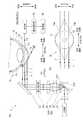
図1は、第1の実施の形態が適用される眼球の光計測装置1の構成の一例を示す図である。図1(a)は、眼球10を上側から見た図(上下方向における断面図)、図1(b)は、眼球10を正面から見た図である。なお、図1に示す眼球10は左目であるとする。図1(a)、(b)には、顔の内側(鼻側)と外側(耳側)とを示す内外方向、顔の前側と後側と示す前後方向、顔の上側と下側とを示す上下方向を矢印などで示している。[First Embodiment]
<
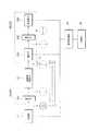
FIG. 1 is a diagram illustrating an example of the configuration of an
この眼球の光計測装置1(以下では、光計測装置1と表記する。)は、被計測者(被験者)の眼球(被検眼)10の前眼房13(後述)内の眼房水の特性の計測に用いる光学系20、光学系20から得られる信号を処理する信号処理部30及び光学系20を制御する制御部40を備えている。 This eyeball optical measuring device 1 (hereinafter referred to as the optical measuring device 1) is a characteristic of aqueous humor in the anterior chamber 13 (described later) of the eyeball (eye to be examined) 10 of the measurement subject (subject). An
なお、第1の実施の形態が適用される光計測装置1は、眼房水を透過した透過光の光強度から、眼房水に含まれる光学活性物質の濃度を計測する。 The
まず、眼球10の構造について説明をする。
図1(a)に示すように、眼球10は、外形がほぼ球形であって、中央にガラス体11がある。なお、図1(a)では、後側の半分の記載を省略している。そして、レンズの役割をする水晶体12が、ガラス体11の一部に埋め込まれている。水晶体12の前側には、前眼房13があり、その前側に角膜14がある。前眼房13及び角膜14は、球形から凸状に飛び出している。
水晶体12の周辺部は虹彩17に囲まれ、その中心が瞳孔15である。水晶体12に接する部分を除いて、ガラス体11は、網膜16で覆われている。そして、網膜16は、強膜18で覆われている。すなわち、眼球10の外側は、角膜14及び強膜18で覆われている。First, the structure of the
As shown in FIG. 1A, the
The peripheral part of the
前眼房13は、角膜14と水晶体12とで囲まれた領域である。この前眼房13は、正面から見た形状が円形である(図1(b)参照)。そして、前眼房13は、眼房水で満たされている。 The
また、図1(b)に示すように、眼球10の表面は、上瞼19aと下瞼19bとで覆われるようになっている。 Further, as shown in FIG. 1B, the surface of the
次に、光学系20について説明する。
図1(a)に示すように、光学系20は、眼球10の前眼房13に向けて光を出射する発光系20Aと、前眼房13を通過した光を受光する受光系20Bとを備える。Next, the
As shown in FIG. 1A, the
まず、発光系20Aは、光源部21、コリメータレンズ22、偏向部23、光反射手段の一例としてのミラー27を備えている。
光源部21は、発光ダイオード(LED)やランプのような波長幅が広い光源であってもよく、レーザのような波長幅が狭い光源であってもよい。また、光源部21は、LED、ランプ又はレーザを複数備えていてもよい。なお、複数の波長を使用してもよい。First, the
The
コリメータレンズ22は、光源部21から出射する広がりをもった光を径が細い平行光(平行光線)にする。角膜14と水晶体12とで囲まれた前眼房13は、小さな領域であるので、前眼房13を透過する光は、径が小さいほどよい。
なお、光源部21が出射した光の径が小さければ、コリメータレンズ22を用いることを要しない。The
If the diameter of the light emitted from the
偏向部23は、光の進む方向を偏向させる部材であって、例えば、ミラー231及びミラー231の反射面の傾きを変更する駆動装置232を備える。このミラー231は、ガリバノミラーやポリゴンミラーであってもよい。ガリバノミラーは、反射面に設けられた軸の回りに反射面を回転させることで、反射面の傾きが変化するものである。ポリゴンミラーは、多面体のミラーを回転させることで、反射面の傾きが変化するものである。ガリバノミラーやポリゴンミラーは、反射面が一の方向(一次元方向)において傾くことから、光を一次元方向に偏向させる。
さらに、ミラー231は、MEMS(Micro Electro Mechanical Systems)で構成されたミラーであってもよい。反射面が点に対して傾くように構成されていれば、反射面は、一の方向及び一の方向に直交する方向において傾くことになる。よって、反射面が二次元方向において傾くことから、光を二次元方向に偏向させる。
なお、これらのミラー231の傾きは、駆動装置232によって制御される。ミラー231がガリバノミラーやポリゴンミラーである場合には、駆動装置232は、例えば、モータ及びモータを制御する回路である。また、ミラー231がMEMSで構成されていれば、駆動装置232は、ミラー27と一体で構成され、静電気力でミラー27の傾きを制御する複数の電極に電位を供給する駆動回路である。
ミラー231は、反射部材の一例であり、駆動装置232は、角度変更手段の一例である。The deflecting
Further, the
Note that the tilt of these
The
ミラー27は、偏向部23で偏向された光が前眼房13を横切るように反射させる。第1の実施の形態においては、ミラー27は、偏向部23と同様に、駆動装置28に接続されている。ミラー27は、ガリバノミラー、ポリゴンミラー、MEMSで構成されたミラーなどである。そして、ミラー27は、駆動装置28によって、傾きが変更されて、入射した光に対する反射角を変更する。
ここで、偏向部23及び駆動装置28が、切替手段の一例である。The
Here, the
受光系20Bは、検出部29を備える。ここでは、検出部29は、例えば、シリコンダイオードなどの受光素子である。検出部29は、前眼房13を通過した光の強度を電気信号に変換する。 The
信号処理部30は、検出部29から電気信号を受信して処理し、眼房水に含まれる光学活性物質の濃度を算出する。
制御部40は、前述したように、光学系20及び信号処理部30を制御する。The
As described above, the
次に眼球10と光学系20との関係を説明する。
まず、図1(a)に示すように、光学系20は、眼球10に対して、発光系20Aから出射した光が、光路αと表記した光路を通って受光系20Bに入射するように設定される。すなわち、光路αは、図1(a)に示すように、眼球10を上下方向の断面図でみた場合において、前眼房13の中央部を通過する。そして、図1(b)に示すように、光路αは、眼球10を正面から見た場合においても、前眼房13の中央部を通過する。
光路αは、前眼房13の眼房水に含まれる光学活性物質の濃度の測定に適する光路である。
なお、図1(a)に示す光路βは、眼球10に対して前側過ぎて、角膜14表面で反射される光路であって、前眼房13の眼房水を通過しない。また、光路γは、眼球10に対して後側過ぎて、虹彩17や強膜18によって遮断される光路であって、前眼房13の眼房水を通過しない。Next, the relationship between the
First, as shown in FIG. 1A, the
The optical path α is an optical path suitable for measuring the concentration of the optically active substance contained in the aqueous humor of the
The optical path β shown in FIG. 1A is an optical path that is too far in front of the
また、図1(b)に示す光路δは、眼球10に対して上側過ぎて、前眼房13の眼房水の通過する長さが短い光路である。さらに、光路が、眼球10に対して光路δよりさらに上側過ぎると、上瞼19aにより遮断される光路となって、前眼房13の眼房水を通過しない。
光路εは、眼球10に対して下側過ぎて、前眼房13の眼房水の通過する長さが短い光路である。さらに、光路が、眼球10に対して光路εよりさらに下側過ぎると、下瞼19bにより遮断される光路となって、前眼房13の眼房水を通過しない。Also, the optical path δ shown in FIG. 1B is an optical path that is too far above the
The optical path ε is an optical path that is too lower than the
なお、光路α、β、γ、δ、εは、眼球10の前眼房13に対する光路の状態及び位置を説明する用語であるとする。 The optical paths α, β, γ, δ, and ε are terms that describe the state and position of the optical path with respect to the
しかし、眼球10と光学系20との相対的な位置関係や、角膜14の形状などの経時変動により、光路がずれて光路αの状態が維持できないことがある。なお、眼球10が光学系20に対して移動してもよく、光学系20が眼球10に対して移動してもよい。以下では、便宜的に、眼球10が光学系20に対して移動するとして説明する。 However, the optical path may be shifted and the state of the optical path α may not be maintained due to a relative positional relationship between the
そして、眼球10に対して、光路αの状態であった光路が、光路βや光路γの状態になったり、光路δや光路εの状態になったりした場合、つまり、光路がわずかにずれた場合には、光路をずらしたり(移動したり)又は切り替えたりすれば、光路を光路αの状態に戻しうる。すなわち、眼球10に対して光学系20を設定し直すことを要しない。 Then, when the optical path that is in the state of the optical path α becomes the state of the optical path β or the optical path γ or the state of the optical path δ or the optical path ε with respect to the
例えば、図1(a)において、光路αの状態にあった光路が、眼球10が後側に移動したために、光路βの状態となったとする。この場合、光路γの位置に新たな光路を設定すればよい。そこで、制御部40の制御に基づいて、偏向部23は、ミラー27への入射位置を切り替えて、光路γの位置に光路を設定する。すなわち、光路を光路αの位置から光路γの位置に設定するように、ミラー27への光の入射位置を切り替えることで、光路γの位置が前眼房13の眼房水に含まれる光学活性物質の濃度の測定に適する光路αの状態に再設定される。 For example, in FIG. 1A, it is assumed that the optical path in the state of the optical path α is in the state of the optical path β because the
同様に、光路αの状態であった光路が、眼球10が前側に移動したために、光路γの状態となったとする。この場合、光路βの位置に新たな光路を設定すればよい。そこで、制御部40の制御に基づいて、偏向部23は、ミラー27への入射位置を切り替えて、光路βの位置に光路を設定する。すなわち、光路を光路αの位置から光路βの位置に設定するように、ミラー27への光の入射位置を切り替えることで、光路βの位置が前眼房13の眼房水に含まれる光学活性物質の濃度の測定に適する光路αの状態に再設定される。 Similarly, it is assumed that the optical path in the state of the optical path α becomes the state of the optical path γ because the
さらに、図1(b)において、光路αの状態であった光路が、眼球10が上側に移動したために、光路εの状態となったとする。この場合、光路δの位置に新たな光路を設定すればよい。そこで、制御部40の制御に基づいて、偏向部23は、ミラー27への入射位置を切り替えて、光路δの位置に光路を設定する。すなわち、光路を光路αの位置から光路δの位置に設定するように、ミラー27への光の入射位置を切り替えることで、光路δの位置が前眼房13の眼房水に含まれる光学活性物質の濃度の測定に適する光路αの状態に再設定される。 Further, in FIG. 1B, it is assumed that the optical path that is in the state of the optical path α is in the state of the optical path ε because the
同様に、光路αの状態であった光路が、眼球10が下側に移動したために、光路δの状態となったとする。この場合、光路εの位置に新たな光路を設定すればよい。そこで、制御部40の制御に基づいて、偏向部23は、ミラー27への入射位置を切り替えて、光路εの位置に光路を設定する。すなわち、光路を光路αの位置から光路εの位置に設定するように、ミラー27への光の入射位置を切り替えることで、光路εの位置が前眼房13の眼房水に含まれる光学活性物質の濃度の測定に適する光路αの状態に再設定される。 Similarly, it is assumed that the optical path in the state of the optical path α becomes the state of the optical path δ because the
これらにおいては、偏向部23のミラー231及びミラー27の傾き(光の入射角)を変更して、光の入射角を変更する。
なお、図1(a)、(b)では、光路を平行移動させている。これは、光学系20における発光系20Aと受光系20Bとの相対的な位置関係が保たれるからである。必ずしも光路は、平行移動でなくてもよい。
また、ミラー231又はミラー27は、平面ミラーとしたが、凹面ミラー、凸面ミラー、球面ミラー、放物面ミラーなどであってもよい。In these, the inclination (light incident angle) of the
In FIGS. 1A and 1B, the optical path is translated. This is because the relative positional relationship between the light emitting
The
以上説明したように、第1の実施の形態の光計測装置1では、眼球10と光学系20との相対的な位置関係や、角膜14の形状等の経時変動などにより、光路αの状態にあった光路がずれても、ミラー27への光の入射位置を切り替えることで、光路が前眼房13の眼房水に含まれる光学活性物質の濃度の測定に適する光路αの状態に再設定される。すなわち、光路が前眼房13を横切るように設定される。
なお、光路が光路αの状態からずれたことは、検出部29からの信号を受信する信号処理部30により容易に検知しうる。よって、制御部40は、信号処理部30からの信号により、偏向部23のミラー231及びミラー27傾き(光の入射角)を制御すればよい。As described above, in the
The deviation of the optical path from the state of the optical path α can be easily detected by the
なお、偏向部23のミラー231及びミラー27は、内外方向において入射角が変更されるとともに、上下方向においても入射角が変更されるとよい。内外方向において入射角が変更される場合には、前後方向(光路α、β、γの間)における一次元方向でのミラー27への光の入射位置の切り替えとなる。また、上下方向において入射角が変更される場合には、上下方向(光路α、δ、εの間)における一次元方向でのミラー27への光の入射位置の切り替えとなる。前後方向及び上下方向において入射角が変更される場合には、前後方向(光路α、β、γの間)及び上下方向(光路α、δ、εの間)における二次元方向でのミラー27への光の入射位置の切り替えとなる。 The incident angle of the
[第2の実施の形態]
第1の実施の形態では、偏向部23のミラー231に加え、ミラー27において、光の入射角を変更した。
第2の実施の形態では、ミラー27への光の入射角を固定する。[Second Embodiment]
In the first embodiment, the incident angle of light is changed in the
In the second embodiment, the incident angle of light to the
図2は、第2の実施の形態が適用される眼球の光計測装置1の構成の一例を示す図である。図2(a)は、眼球10を上側から見た図(上下方向における断面図)、図2(b)は、眼球10を正面から見た図である。第1の実施の形態が適用される光計測装置1と同様の部分は、同じ符号を付して説明を省略する。 FIG. 2 is a diagram illustrating an example of the configuration of the
第2の実施の形態が適用される眼球の光計測装置1では、偏向部23とミラー27との間に、テレセントリックfθレンズを含むテレセントリック光学系24が設けられている。そして、ミラー27は、第1の実施の形態で備えていた駆動装置28を備えない。ここでは、偏向部23及びテレセントリック光学系24が切替手段の一例である。
テレセントリックfθレンズは、入射した光を平らな平面に対して垂直に集光するレンズである。すなわち、図2に示すように、光は、偏向部23のミラー231で反射されて、テレセントリック光学系24に対して斜めに入射しても、テレセントリック光学系24からは、互いに平行な関係で出射する。
よって、ミラー27の入射角(傾き)を固定しても、ミラー27への入射位置を切り替えることで、眼球10へ向かう光路が、平行移動するように、互いに平行な関係で変更される。In the eyeball
The telecentric fθ lens is a lens that collects incident light perpendicular to a flat plane. That is, as shown in FIG. 2, even if the light is reflected by the
Therefore, even if the incident angle (tilt) of the
よって、ミラー27への入射位置を切り替えは、偏向部23におけるミラー231の反射角の制御でよい。すなわち、ミラー27への入射位置を切り替える制御が簡易になる。 Therefore, the incident position on the
また、ミラー27は眼球10に近接して設けられるため、第1の実施の形態が適用される光計測装置1では、ミラー27の入射角を変更するためにミラー27を動かす(回転させる)と、力学的な力が被計測者に加わることになってしまう。しかし、第2の実施の形態が適用される光計測装置1では、ミラー27の入射角が固定されているので、力学的な力が被計測者に加わることが抑制される。 Further, since the
ミラー27の入射角(傾き)を固定することを除いて、ミラー27への入射位置の切り替えについては、第1の実施の形態において説明したことと同様であるので、説明を省略する。 Except for fixing the incident angle (tilt) of the
[第3の実施の形態]
第1の実施の形態及び第2の実施の形態では、前眼房13の眼房水の透過する光の強度の変化から、眼房水に含まれる光学活性物質の濃度を測定した。
第3の実施の形態では、旋光性(旋光度)を利用して、眼房水に含まれるグルコースなどの光学活性物質の濃度を計測する。[Third Embodiment]
In the first embodiment and the second embodiment, the concentration of the optically active substance contained in the aqueous humor is measured from the change in the intensity of light transmitted through the aqueous humor of the
In the third embodiment, the concentration of an optically active substance such as glucose contained in aqueous humor is measured using optical rotation (optical rotation).
図3は、第3の実施の形態が適用される眼球の光計測装置1の構成の一例を示す図である。図3(a)は、眼球10を上側から見た図(上下方向における断面図)、図3(b)は、眼球10を正面から見た図である。第2の実施の形態が適用される光計測装置1(一部を除いて、第1の実施の形態が適用される光計測装置1)と同様の部分は、同じ符号を付して説明を省略する。 FIG. 3 is a diagram illustrating an example of the configuration of the
第3の実施の形態が適用される光計測装置1は、第2の実施の形態が適用される光計測装置1において、偏光制御部25を備えている。偏光制御部25は、偏光制御手段の一例である。
偏光制御部25は、偏光子、波長板などを含んで構成されている。そして、光源部21が出射する光から、予め定められた偏光(直線偏光、楕円偏光、円偏光など)を取り出す。The
The
ミラー27による反射において、入射面に平行な成分(P)及び垂直な成分(S)のそれぞれの反射率は、ミラー27の屈折率及び入射角に依存する。このため、ミラー27に偏光を入射させると、入射角により、反射光の偏光状態が変ることがある。例えば、直線偏光を入射させる場合、ある入射角では、反射光も直線偏光となることがあり、異なる入射角では、反射光が楕円偏光になることがある。
よって、ミラー27への入射角は、固定であることがよい。In the reflection by the
Therefore, the angle of incidence on the
そこで、第3の実施の形態が適用される光計測装置1では、第2の実施の形態と同様に、テレセントリックfθレンズを含むテレセントリック光学系24を用い、ミラー27への入射角の変化による偏光状態の変化を考慮しなくてもよいようにしている。
同様に、偏光がレンズを通過すると、偏光状態が変化する。よって、テレセントリック光学系24におけるテレセントリックfθレンズの後段、つまりテレセントリックfθレンズとミラー27との間に偏光制御部25を設けている。
ここでも、偏向部23及びテレセントリック光学系24が切替手段の一例である。Therefore, in the
Similarly, the polarization state changes as the polarized light passes through the lens. Therefore, the
Again, the
そして、検出部29は、後述するように、旋光角を検出するための、検光子などを含んでいる。 The
なお、ミラー27の屈折率、入射光の偏光状態(振動面の向き及び直線偏光、楕円偏光)及び入射角が既知であれば、反射光の偏光状態は算出しうる。よって、第1の実施の形態が適用される眼球の光計測装置1に、偏光制御部25を設けて、旋光性を利用して光学活性物質の濃度を計測するようにしてもよい。 If the refractive index of the
旋光性(旋光度)を用いて光学活性物質の濃度を計測することを除いて、ミラー27への光の入射位置の切り替えについては、第1の実施の形態及び第2の実施の形態において説明したことと同様であるので、説明を省略する。 Except for measuring the optically active substance concentration using optical rotation (optical rotation), switching of the light incident position on the
(光学活性物質の濃度算出)
図4は、光計測装置1によって、前眼房13における眼房水に含まれる光学活性物質による振動面の回転角(旋光度)を計測する方法を説明する図である。ここでは、説明を容易にするため、光路を折り曲げない構成とし、テレセントリック光学系24、ミラー27の記載を省略している。
なお、光学系20における偏光制御部25は、偏光子251を備えているとし、検出部29は、補償子291、検光子292、受光素子293を備えているとする。
また、図4に示す光源部21、偏光制御部25における偏光子251、前眼房13、検出部29における補償子291、検光子292及び受光素子293のそれぞれの間において、光の進行方向から見た偏光の様子を円内の矢印で示している。
なお、光学系20は、他の素子(光学部品など)を備えていてもよい。(Calculation of optically active substance concentration)
FIG. 4 is a diagram for explaining a method of measuring the rotation angle (optical rotation) of the vibration surface by the optically active substance contained in the aqueous humor in the
It is assumed that the
In addition, the
The
偏光子251は、例えば、ニコルプリズムなどであって、入射した光から、予め定められた振動面の直線偏光を通過させる。 The
補償子291は、例えばガーネット等を用いたファラデー素子などの磁気光学素子であって、磁場によって直線偏光の振動面を回転させる。
検光子292は、偏光子251と同様の部材であって、予め定められた振動面の直線偏光を通過させる。
受光素子293は、シリコンダイオードなどであって、光の強度に対応した出力信号を出力する。The
The
The
光源部21は、ランダムな振動面を持つ光を出射する。そして、偏光子251は、予め定められた振動面の直線偏光を通過させる。図4においては、偏光子251は、例として、紙面に平行な振動面の直線偏光を通過させる。
偏光子251を通過した直線偏光は、前眼房13における眼房水に含まれる光学活性物質により、振動面が回転する。図4では、振動面は角度αM(旋光度αM)回転する。The
The plane of polarization of the linearly polarized light that has passed through the
次に、前眼房13における眼房水に含まれる光学活性物質により回転した振動面を、補償子291により元に戻す。補償子291がファラデー素子などの磁気光学素子である場合には、補償子291に磁界を印加することで、補償子291を通過する光の振動面を回転させる。
そして、検光子292を通過した直線偏光を受光素子293により受光し、光の強度に対応した出力信号に変換する。Next, the vibrating surface rotated by the optically active substance contained in the aqueous humor in the
The linearly polarized light that has passed through the
ここで、光学系20による旋光度αMの計測方法の一例を説明する。
まず、光源部21を出射した光が前眼房13を通過させない状態において、光源部21、偏光子251、補償子291、検光子292、及び受光素子293が含まれる光学系20を用いて、受光素子293からの出力信号が最小になるよう、補償子291及び検光子292を設定する。図4に示す例において、光が前眼房13を通過させない状態では、偏光子251を通過した直線偏光の振動面は、検光子292を通過する振動面と直交する。Here, an example of a method for measuring the optical rotation αM by the
First, in a state where light emitted from the
次に、光が前眼房13を通過する状態とする。すると、前眼房13における眼房水に含まれる光学活性物質によって、振動面が回転する。このため、受光素子293からの出力信号は、最小値から外れる。そこで、受光素子293からの出力信号が最小になるように、補償子291に磁界を印加して振動面を回転させる。すなわち、補償子291から出射する光の振動面を、検光子292を通過する振動面と直交させる。
この補償子291によって回転させた振動面の角度が、眼房水に含まれる光学活性物質によって発生した旋光度αMに対応する。ここで、補償子291に印加した磁場の大きさと回転した振動面の角度との関係は、事前に知られている。したがって、補償子291に印加した磁場の大きさから、旋光度αMが分かる。Next, it is assumed that light passes through the
The angle of the vibration surface rotated by the
具体的には、光源部21から前眼房13における眼房水に複数の波長λ(波長λ1、λ2、λ3、…)の光を入射し、それぞれに対して旋光度αM(旋光度αM1、αM2、αM3、…)を求める。これらの波長λと旋光度αMとの組が、信号処理部30に取り込まれ、求めたい光学活性物質の濃度が算出される。Specifically, light having a plurality of wavelengths λ (wavelengths λ1 , λ2 , λ3 ,...) Is incident on the aqueous humor in the
付言すると、眼房水には、前述したように複数の光学活性物質が含まれている。よって、計測された旋光度αMは、複数の光学活性物質それぞれによる旋光度αMの和である。そこで、計測された旋光度αMから、求めたい光学活性物質(ここでは、グルコース)の濃度を算出することが必要となる。求めたい光学活性物質の濃度の算出は、公知の方法を用いればよいので、ここでは説明を省略する。In addition, the aqueous humor includes a plurality of optically active substances as described above. Therefore, the measured optical rotation αM is the sum of the optical rotation αM by each of the plurality of optically active substances. Therefore, it is necessary to calculate the concentration of the optically active substance (here, glucose) to be obtained from the measured optical rotation αM. Since the calculation of the concentration of the optically active substance to be obtained may be performed using a known method, description thereof is omitted here.
また、図4では、偏光子251の振動面が紙面に平行であって、検光子292を通過する前の振動面が紙面に垂直であるとしている。しかし、光源部21を出射した光が前眼房13を通過させない状態において、補償子291によって振動面が回転する場合には、検光子292を通過する前の振動面が紙面に平行な面から傾いていてもよい。すなわち、光が前眼房13における眼房水を通過させない状態において、受光素子293からの出力信号が最小になるように、補償子291と検光子292とを設定すればよい。 In FIG. 4, it is assumed that the vibration surface of the
また、ここでは旋光度αMを求める方法として補償子291を用いた例を述べたが、補償子291以外で旋光度αMを求めてもよい。さらに、ここでは振動面の回転角(旋光度αM)を測定する最も基本的な測定法である直交偏光子法(ただし補償子291を使用)について示したが、回転検光子法やファラデー変調法、光学遅延変調法といった他の測定方法を適用してもよい。Furthermore, here has been described the example using the
[第4の実施の形態]
第3の実施の形態が適用される光計測装置1では、テレセントリック光学系24にテレセントリックfθレンズを用いることで、ミラー27に入射する角度を固定にした。第4の実施の形態が適用される光計測装置1では、テレセントリック光学系24の代わりに、偏向部23のミラー231を移動させることで、光路を切り替える。
第4の実施の形態では、偏光制御部25を設けて、旋光性(旋光度)を利用してグルコースなどの光学活性物質の濃度を計測する。なお、偏光制御部25を設けず、濃度によりグルコースなどの光学活性物質の濃度を計測してもよい。[Fourth Embodiment]
In the
In the fourth embodiment, the
図5は、第4の実施の形態が適用される眼球の光計測装置1の構成の一例を示す図である。図5(a)は、眼球10を上側から見た図(上下方向における断面図)、図5(b)は、眼球10を正面から見た図である。第3の実施の形態が適用される光計測装置1(一部を除いて、第1の実施の形態が適用される光計測装置1)と同様の部分は、同じ符号を付して説明を省略する。 FIG. 5 is a diagram illustrating an example of the configuration of the
第4の実施の形態が適用される光計測装置1は、テレセントリック光学系24の代わりに、集光レンズ26を設けている。そして、偏向部23は、ミラー231と、ミラー231を搭載して一方向に移動させる直動ステージ233とを備えている。直動ステージ233は、移動手段の一例である。
すなわち、直動ステージ233により、ミラー231の反射面を光路の方向(光が進行する前後方向)に移動させる。これにより、光のミラー27への入射位置が切り替えられる。そして、光路が前眼房13の眼房水に含まれる光学活性物質の濃度の測定に適する光路αの状態に設定される。すなわち、光路が前眼房13を横切るように設定される。
ここでも、偏向部23及び集光レンズ26が切替手段の一例である。The
In other words, the reflecting surface of the
Again, the
第4の実施の形態では、光のミラー27への入射位置は、直動ステージ233の移動方向に限定される。すなわち、光のミラー27への入射位置の切り替えは、一次元方向において行われる。例えば、図5(a)では、光路は、顔の前後方向の移動に限定される。
よって、図5(b)に示すように、光路を、顔の上下方向に移動させる場合には、図5(a)において、光源部21、コリメータレンズ22を紙面に対して垂直方向に配置するとともに、直動ステージ233の移動方向も紙面に垂直方向とし、直動ステージ233上のミラー231の向きを、光源部21からコリメータレンズ22を通して出射される光がミラー27側に反射されるように設定することになる。In the fourth embodiment, the incident position of light on the
Therefore, as shown in FIG. 5B, when the optical path is moved in the vertical direction of the face, the
なお、直動ステージ233を用いる代わりに、ミラー231の裏面に、ピエゾ素子を貼り付けて、ミラー231の表面が移動するようにしてもよい。このとき、直動ステージ233を、ピエゾ素子を駆動する駆動装置とすればよい。 Instead of using the
[第5の実施の形態]
第5の実施の形態が適用される眼球の光計測装置1は、眼球10の前眼房13の周囲が液体中に浸漬されている。この状態は、液浸と表現されることがある。
図6は、第5の実施の形態が適用される眼球の光計測装置1の構成の一例を示す図である。図6(a)は、眼球10を上側から見た図(上下方向における断面図)、図6(b)は、眼球10を正面から見た図である。なお、後述する液浸部50を除いた、光計測装置1の構成は、図3に示した第3の実施の形態と同様である。よって、同様の部分は同じ符号を付して説明を省略し、異なる部分を説明する。[Fifth Embodiment]
In the eyeball
FIG. 6 is a diagram illustrating an example of the configuration of the
液浸部50は、容器51と、容器51を満たす液体52とを備えている。液浸部50の容器51を眼球10の周りの顔の表面に押し当てることで、眼球10の前眼房13の周囲が液体52に浸漬される。液体52は、眼房水との屈折率差が小さいことがよい。例えば、水、生理食塩水などを用い得る。
そして、液浸部50は、前眼房13を横切るように光が通過するように、容器51の光路に対応する部分に、光が通過する入射窓53及び出射窓54を備えている。入射窓53は、ミラー27で反射した光が垂直に入射するように構成され、出射窓54は、液体52及び前眼房13を通過した光が垂直に出射するように構成されている。なお、眼球10の前眼房13の周囲(例えば、角膜14)における光の入射位置が液体52に浸る構成であれば、容器51の大きさや形状は問わない。The
The
このように、液浸部50は、ミラー27で反射した光が角膜14表面で屈折して、方向が変化することを抑制する。すなわち、角膜14などの形状の影響を受けにくくなり、前眼房13を横切る光路が設定しやすくなる。なお、光路βは、角膜14表面で反射せずに進むが、前眼房13を通過する距離が短い。 As described above, the
液浸部50は、他の実施の形態が適用される眼球の光計測装置1に適用してもよい。 The
[第6の実施の形態]
第2の実施の形態から第4の実施の形態が適用される眼球の光計測装置1は、ミラー27が予め定められた入射角に設定されていた。そして、ミラー27は、眼球10から離れて配置されていた。
第6の実施の形態では、ミラー27は、眼球10の表面に接触して用いられるミラー付きコンタクト部材60に設けられている。ミラー付きコンタクト部材60は、装着部材の一例である。[Sixth Embodiment]
In the eyeball
In the sixth embodiment, the
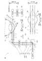
図7は、第6の実施の形態が適用される眼球の光計測装置1の構成の一例を示す図である。図7(a)は、眼球10を上側から見た図(上下方向における断面図)、図7(b)は、眼球10を正面から見た図である。なお、後述するミラー付きコンタクト部材60を除いた光計測装置1の構成は、図3に示した第3の実施の形態と同様である。よって、同様の部分は同じ符号を付して説明を省略し、異なる部分を説明する。 FIG. 7 is a diagram illustrating an example of the configuration of the
図7(a)に示すように、ミラー付きコンタクト部材60は、いわゆるコンタクトレンズと同様の眼球用の部材であって、眼球10における角膜14の表面(眼球面)に装着される。なお、眼球10における角膜14の表面(眼球面)に装着されることを、ここでは、眼球10に装着されると表現する。
そして、ミラー付きコンタクト部材60は、基体61の内部にミラー27が設けられている。As shown in FIG. 7A, the
The
基体61は、例えば、ポリヒドロキシエチルメタクリレート、ポリメチルメタクリレート、シリコーン共重合体、フッ素含有化合物などの樹脂である。基体61の屈折率が、眼球10における前眼房13の眼房水、角膜14などの屈折率に近いと、ミラー付きコンタクト部材60と眼球10との間の界面での屈折が抑制される。よって、眼球10の前眼房13を横切る光路の設定が容易になる。なお、光路βは、角膜14表面で反射せずに進むが、前眼房13を通過する距離が短い。 The
そして、基体61は、ミラー27に向かって光が入射する部分が、光に対して垂直な平面62で構成されている。また、基体61は、検出部29に向かって光が出射する部分が、光に対して垂直な平面63で構成されている。これにより、ミラー付きコンタクト部材60への光の入射、ミラー付きコンタクト部材60からの光の出射において、基体61の屈折により光路が折り曲がることが抑制される。 The
図7(b)に示すように、ミラー27の外形は、四角形である。なお、ミラー27の外形は、円弧状など他の形状であってもよい。
なお、基体61は、円形である必要はなく、角膜14に装着できる構成であれば、四角形など、他の形状であってもよい。As shown in FIG. 7B, the outer shape of the
The
なお、第6の実施の形態で説明したミラー付きコンタクト部材60を第2の実施の形態から第4の実施の形態に適用してもよい。 The
上記では種々の実施の形態を説明したが、これらの実施の形態を組み合わせて構成してもよい。
また、本開示は上記の実施の形態に何ら限定されるものではなく、本開示の要旨を逸脱しない範囲で種々の形態で実施することができる。Although various embodiments have been described above, these embodiments may be combined.
Further, the present disclosure is not limited to the above-described embodiment, and can be implemented in various forms without departing from the gist of the present disclosure.
1…光計測装置、10…眼球、13…前眼房、14…角膜、20…光学系、20A…発光系、20B…受光系、21…光源部、23…偏向部、24…テレセントリック光学系、25…偏光制御部、27、231…ミラー、28、232…駆動装置、29…検出部、30…信号処理部、40…制御部、50…液浸部、60…ミラー付きコンタクト部材、233…直動ステージ、251…偏光子、291…補償子、292…検光子、293…受光素子、α、β、γ、δ、ε…光路DESCRIPTION OF
Claims (10)
Translated fromJapanese前記光が前記前眼房を横切る状態からの移動を抑制するように、前記光反射手段への当該光の入射位置を切り替える切替手段と
を備える眼球の光計測装置。A light reflecting means for reflecting light in a direction across the anterior chamber of the eyeball;
An eyeball optical measurement device comprising: switching means for switching an incident position of the light to the light reflecting means so as to suppress movement of the light from a state of crossing the anterior chamber.
前記光の入射角が予め定められた角度に設定され、
前記切替手段は、
前記光を反射させる反射部材と、
前記反射部材の前記光に対する反射角を変更する角度変更手段と、
前記反射部材が反射した前記光を通過させて前記光反射手段に出射するテレセントリック光学系と、を備える
ことを特徴とする請求項1に記載の眼球の光計測装置。The light reflecting means is
The incident angle of the light is set to a predetermined angle,
The switching means is
A reflecting member that reflects the light;
Angle changing means for changing a reflection angle of the reflecting member with respect to the light;
The eyeball optical measurement device according to claim 1, further comprising: a telecentric optical system that transmits the light reflected by the reflecting member and emits the light to the light reflecting unit.
前記光の入射角が予め定められた角度に設定され、
前記切替手段は、
前記光を反射させる反射部材と、
前記反射部材を前記光の進行する前後方向に移動させる移動手段と、を備える
ことを特徴とする請求項1に記載の眼球の光計測装置。The light reflecting means is
The incident angle of the light is set to a predetermined angle,
The switching means is
A reflecting member that reflects the light;
The eyeball optical measurement device according to claim 1, further comprising a moving unit that moves the reflection member in the front-rear direction in which the light travels.
前記前眼房を横切る光が、前記眼球の前後方向および上下方向の少なくとも一方向に平行移動するように、前記光反射手段への当該光の入射位置を切り替える切替手段と
を備える眼球の光計測装置。A light reflecting means for reflecting light in a direction across the anterior chamber of the eyeball;
Optical measurement of an eyeball comprising switching means for switching the incident position of the light to the light reflecting means so that light traversing the anterior chamber moves in parallel in at least one of the front-rear direction and the up-down direction of the eyeball. apparatus.
Priority Applications (3)
| Application Number | Priority Date | Filing Date | Title |
|---|---|---|---|
| JP2016119015AJP6790479B2 (en) | 2016-06-15 | 2016-06-15 | Eye light measuring device |
| US15/594,738US20170360296A1 (en) | 2016-06-15 | 2017-05-15 | Optical measurement apparatus for eyeball |
| CN201710451620.0ACN107518904A (en) | 2016-06-15 | 2017-06-15 | Optical measuring device for eyeball |
Applications Claiming Priority (1)
| Application Number | Priority Date | Filing Date | Title |
|---|---|---|---|
| JP2016119015AJP6790479B2 (en) | 2016-06-15 | 2016-06-15 | Eye light measuring device |
Publications (2)
| Publication Number | Publication Date |
|---|---|
| JP2017221418Atrue JP2017221418A (en) | 2017-12-21 |
| JP6790479B2 JP6790479B2 (en) | 2020-11-25 |
Family
ID=60661468
Family Applications (1)
| Application Number | Title | Priority Date | Filing Date |
|---|---|---|---|
| JP2016119015AActiveJP6790479B2 (en) | 2016-06-15 | 2016-06-15 | Eye light measuring device |
Country Status (3)
| Country | Link |
|---|---|
| US (1) | US20170360296A1 (en) |
| JP (1) | JP6790479B2 (en) |
| CN (1) | CN107518904A (en) |
Citations (8)
| Publication number | Priority date | Publication date | Assignee | Title |
|---|---|---|---|---|
| US20010031914A1 (en)* | 1997-06-12 | 2001-10-18 | Tecmed, Incorporated (A New Mexico Corporation) | Method and device for glucose concentration measurement with special attention to blood glucose determinations |
| JP2002000569A (en)* | 2000-06-23 | 2002-01-08 | Tokyo Boeki Medical System Kk | Attachment for measuring aqueous humor |
| US20060187462A1 (en)* | 2005-01-21 | 2006-08-24 | Vivek Srinivasan | Methods and apparatus for optical coherence tomography scanning |
| US20080218696A1 (en)* | 2005-07-01 | 2008-09-11 | Jose Mir | Non-Invasive Monitoring System |
| US20150150460A1 (en)* | 2012-06-07 | 2015-06-04 | The Trustees Of Dartmouth College | Methods And Systems For Intraoperative Tumor Margin Assessment In Surgical Cavities And Resected Tissue Specimens |
| JP2015192861A (en)* | 2014-03-20 | 2015-11-05 | 富士ゼロックス株式会社 | Optical measurement apparatus for eyeball |
| JP2016028682A (en)* | 2014-07-14 | 2016-03-03 | 学校法人北里研究所 | Eyeball measurement device and eyeball measurement method |
| JP2016099327A (en)* | 2014-11-26 | 2016-05-30 | 富士ゼロックス株式会社 | Optical measurement device for eyeball |
Family Cites Families (8)
| Publication number | Priority date | Publication date | Assignee | Title |
|---|---|---|---|---|
| US5359372A (en)* | 1993-02-23 | 1994-10-25 | Tomey Corp. | Contact lens for intraocular observation |
| US6594021B1 (en)* | 2000-04-18 | 2003-07-15 | Eyetech Vision, Inc. | Analysis system for interferometric scanning of donor corneal tissue |
| JP2002000570A (en)* | 2000-06-23 | 2002-01-08 | Tokyo Boeki Medical System Kk | Positioning device for measuring eyeball |
| DE10108797A1 (en)* | 2001-02-21 | 2002-09-05 | Zeiss Carl Jena Gmbh | Procedure for determining distances at the anterior segment of the eye |
| US6885882B2 (en)* | 2002-05-28 | 2005-04-26 | Cote Gerard L. | Method and apparatus for non-invasive glucose sensing through the eye |
| JP4409331B2 (en)* | 2004-03-30 | 2010-02-03 | 株式会社トプコン | Optical image measuring device |
| JP5597012B2 (en)* | 2010-03-31 | 2014-10-01 | キヤノン株式会社 | Tomographic imaging apparatus and tomographic imaging method |
| EP2745819B1 (en)* | 2012-12-18 | 2017-08-09 | Telesto GmbH | Laser therapy system for treatment of a collagen structure and varicose blood vessels in an eye |
- 2016
- 2016-06-15JPJP2016119015Apatent/JP6790479B2/enactiveActive
- 2017
- 2017-05-15USUS15/594,738patent/US20170360296A1/ennot_activeAbandoned
- 2017-06-15CNCN201710451620.0Apatent/CN107518904A/enactivePending
Patent Citations (8)
| Publication number | Priority date | Publication date | Assignee | Title |
|---|---|---|---|---|
| US20010031914A1 (en)* | 1997-06-12 | 2001-10-18 | Tecmed, Incorporated (A New Mexico Corporation) | Method and device for glucose concentration measurement with special attention to blood glucose determinations |
| JP2002000569A (en)* | 2000-06-23 | 2002-01-08 | Tokyo Boeki Medical System Kk | Attachment for measuring aqueous humor |
| US20060187462A1 (en)* | 2005-01-21 | 2006-08-24 | Vivek Srinivasan | Methods and apparatus for optical coherence tomography scanning |
| US20080218696A1 (en)* | 2005-07-01 | 2008-09-11 | Jose Mir | Non-Invasive Monitoring System |
| US20150150460A1 (en)* | 2012-06-07 | 2015-06-04 | The Trustees Of Dartmouth College | Methods And Systems For Intraoperative Tumor Margin Assessment In Surgical Cavities And Resected Tissue Specimens |
| JP2015192861A (en)* | 2014-03-20 | 2015-11-05 | 富士ゼロックス株式会社 | Optical measurement apparatus for eyeball |
| JP2016028682A (en)* | 2014-07-14 | 2016-03-03 | 学校法人北里研究所 | Eyeball measurement device and eyeball measurement method |
| JP2016099327A (en)* | 2014-11-26 | 2016-05-30 | 富士ゼロックス株式会社 | Optical measurement device for eyeball |
Also Published As
| Publication number | Publication date |
|---|---|
| CN107518904A (en) | 2017-12-29 |
| JP6790479B2 (en) | 2020-11-25 |
| US20170360296A1 (en) | 2017-12-21 |
Similar Documents
| Publication | Publication Date | Title |
|---|---|---|
| JP5800100B1 (en) | Eyeball optical measuring device | |
| US20170049320A1 (en) | Optical measuring apparatus and method of outputting light and receiving the light | |
| US9936874B2 (en) | Optical measurement apparatus and light irradiation/reception method | |
| JP6841146B2 (en) | Eye light measuring device and eye light measuring method | |
| JP5958635B2 (en) | Eyeball optical measuring device | |
| JP6790479B2 (en) | Eye light measuring device | |
| JP5950007B1 (en) | Optical measuring device | |
| JP5907325B1 (en) | Measuring device | |
| US20170188824A1 (en) | Optical measurement apparatus for eyeball | |
| JP2018089202A (en) | Eyeball optical measurement apparatus and eyeball optical measurement method | |
| US20250176870A1 (en) | Device and method for determining a glucose concentration | |
| JP2018114224A (en) | Optical measurement apparatus | |
| JP5900689B2 (en) | Optical measurement method of eyeball | |
| JP5950008B1 (en) | Optical measuring device | |
| JP6172329B1 (en) | Optical measurement system for eyeball and mounting member for eyeball | |
| JP6939044B2 (en) | Eyeball light measuring device and light measuring device | |
| JP6661917B2 (en) | Eye light measuring device and eye light measuring method |
Legal Events
| Date | Code | Title | Description |
|---|---|---|---|
| A621 | Written request for application examination | Free format text:JAPANESE INTERMEDIATE CODE: A621 Effective date:20190423 | |
| A977 | Report on retrieval | Free format text:JAPANESE INTERMEDIATE CODE: A971007 Effective date:20200318 | |
| A131 | Notification of reasons for refusal | Free format text:JAPANESE INTERMEDIATE CODE: A131 Effective date:20200324 | |
| A521 | Request for written amendment filed | Free format text:JAPANESE INTERMEDIATE CODE: A523 Effective date:20200520 | |
| A131 | Notification of reasons for refusal | Free format text:JAPANESE INTERMEDIATE CODE: A131 Effective date:20200804 | |
| A521 | Request for written amendment filed | Free format text:JAPANESE INTERMEDIATE CODE: A523 Effective date:20200827 | |
| TRDD | Decision of grant or rejection written | ||
| A01 | Written decision to grant a patent or to grant a registration (utility model) | Free format text:JAPANESE INTERMEDIATE CODE: A01 Effective date:20201006 | |
| A61 | First payment of annual fees (during grant procedure) | Free format text:JAPANESE INTERMEDIATE CODE: A61 Effective date:20201019 | |
| R150 | Certificate of patent or registration of utility model | Ref document number:6790479 Country of ref document:JP Free format text:JAPANESE INTERMEDIATE CODE: R150 | |
| S533 | Written request for registration of change of name | Free format text:JAPANESE INTERMEDIATE CODE: R313533 | |
| R350 | Written notification of registration of transfer | Free format text:JAPANESE INTERMEDIATE CODE: R350 |