Movatterモバイル変換


[0]ホーム

URL:


JP2017217862A - Printer - Google Patents

Printer
Download PDF

Info

Publication number
JP2017217862A
JP2017217862AJP2016115132AJP2016115132AJP2017217862AJP 2017217862 AJP2017217862 AJP 2017217862AJP 2016115132 AJP2016115132 AJP 2016115132AJP 2016115132 AJP2016115132 AJP 2016115132AJP 2017217862 AJP2017217862 AJP 2017217862A
Authority
JP
Japan
Prior art keywords
opening
printer
paper
shaft
closing
Prior art date
Legal status (The legal status is an assumption and is not a legal conclusion. Google has not performed a legal analysis and makes no representation as to the accuracy of the status listed.)
Granted
Application number
JP2016115132A
Other languages
Japanese (ja)
Other versions
JP6872859B2 (en
Inventor
星 和行
Kazuyuki Hoshi
和行 星
Current Assignee (The listed assignees may be inaccurate. Google has not performed a legal analysis and makes no representation or warranty as to the accuracy of the list.)
Sato Corp
Original Assignee
Sato Holdings Corp
Priority date (The priority date is an assumption and is not a legal conclusion. Google has not performed a legal analysis and makes no representation as to the accuracy of the date listed.)
Filing date
Publication date
Application filed by Sato Holdings CorpfiledCriticalSato Holdings Corp
Priority to JP2016115132ApriorityCriticalpatent/JP6872859B2/en
Publication of JP2017217862ApublicationCriticalpatent/JP2017217862A/en
Application grantedgrantedCritical
Publication of JP6872859B2publicationCriticalpatent/JP6872859B2/en
Activelegal-statusCriticalCurrent
Anticipated expirationlegal-statusCritical

Links

Images

Landscapes

Abstract

Translated fromJapanese

【課題】プリンタにおいて、用紙ガイド部の調整を行う作業負担を削減すること。
【解決手段】一実施形態に係るプリンタは、印字媒体を収容する収容部と、軸部を支点として揺動可能な揺動部と、当該軸部に係合し、揺動部の揺動によって収容部に収容される印字媒体の幅方向に移動するガイド部とを有する。例えば、印字媒体は帯状の連続紙であり、帯状の連続紙がロール状に巻回されたロール体の形態で収容部に収容される。揺動部は、例えば、収容部を開放又は閉鎖する開閉部であってもよい。
【選択図】図1
An object of the present invention is to reduce a work load for adjusting a paper guide portion in a printer.
A printer according to an embodiment engages with an accommodating portion that accommodates a print medium, an oscillating portion that can oscillate about a shaft portion as a fulcrum, and the oscillating portion. And a guide portion that moves in the width direction of the print medium accommodated in the accommodating portion. For example, the print medium is a belt-like continuous paper, and the belt-like continuous paper is accommodated in the accommodating portion in the form of a roll body wound in a roll shape. The swinging unit may be, for example, an opening / closing unit that opens or closes the housing unit.
[Selection] Figure 1

Description

Translated fromJapanese

本発明は、プリンタに関する。  The present invention relates to a printer.

従来から、ロール紙を収納するプリンタにおいて、ロール紙の幅方向の端位置を規定する用紙ガイド部が知られている。例えば、特許文献1には、ロール紙収納部に収納されたロール紙から引き出された連続用紙の用紙幅方向の端位置を規定するサイドガイド(用紙ガイド部の一例)を有しているプリンタについて記載されている。このプリンタにおいてサイドガイドは、用紙幅方向にスライド可能であり、用紙幅方向にスライドさせるとロール紙収納部のロール紙の端面に当接可能となっている。  2. Description of the Related Art Conventionally, in a printer that stores roll paper, a paper guide portion that defines an end position in the width direction of the roll paper is known. For example,Patent Document 1 discloses a printer having a side guide (an example of a paper guide unit) that defines an end position in a paper width direction of continuous paper drawn from roll paper stored in a roll paper storage unit. Have been described. In this printer, the side guide is slidable in the paper width direction, and can be brought into contact with the end face of the roll paper in the roll paper storage unit when slid in the paper width direction.

特開2014−37294号公報JP 2014-37294 A

特許文献1に記載されたような用紙ガイド部を備えた従来のプリンタでは、用紙ガイド部の用紙幅方向のスライド調整をユーザが行う必要があるため、その調整作業が煩雑であった。  In a conventional printer having a paper guide portion as described inPatent Document 1, it is necessary for the user to perform slide adjustment of the paper guide portion in the paper width direction, and the adjustment work is complicated.

そこで、本開示の目的は、プリンタにおいて用紙ガイド部の調整を行う作業負担を削減することができるようにすることである。  Accordingly, an object of the present disclosure is to reduce a work burden of adjusting a paper guide unit in a printer.

本開示の一観点は、印字媒体を収容する収容部と、軸部を支点として揺動可能な揺動部と、前記軸部に係合し、前記揺動部の揺動によって前記収容部に収容される前記印字媒体の幅方向に移動するガイド部と、を有するプリンタである。  One aspect of the present disclosure includes an accommodating portion that accommodates a print medium, an oscillating portion that can oscillate about a shaft portion as a fulcrum, and the shaft portion that engages the oscillating portion. And a guide unit that moves in a width direction of the print medium to be accommodated.

本開示に係るプリンタによれば、用紙ガイド部の調整を行う作業負担を削減することができる。  According to the printer according to the present disclosure, it is possible to reduce the work burden of adjusting the paper guide unit.

実施形態に係るプリンタについて、開閉部が開放状態である場合を示す斜視図である。It is a perspective view which shows the case where an opening-and-closing part is an open state about the printer concerning an embodiment.実施形態に係るプリンタについて、開閉部が閉鎖状態である場合を示す斜視図である。It is a perspective view which shows the case where an opening / closing part is a closed state about the printer which concerns on embodiment.実施形態に係るプリンタの主要部分についての側面図である。It is a side view about the principal part of the printer concerning an embodiment.実施形態に係るプリンタのトルク伝達機構の分解斜視図である。It is a disassembled perspective view of the torque transmission mechanism of the printer which concerns on embodiment.実施形態に係るプリンタのトルク伝達機構と用紙ガイド部の分解斜視図である。FIG. 4 is an exploded perspective view of a torque transmission mechanism and a paper guide unit of the printer according to the embodiment.図5の矢視Aから見た用紙ガイド部の図である。FIG. 6 is a view of a paper guide portion viewed from an arrow A in FIG. 5.実施形態に係るプリンタのトルク伝達機構の取り付け方法を説明する図である。It is a figure explaining the attachment method of the torque transmission mechanism of the printer which concerns on embodiment.実施形態に係るプリンタのトルク伝達機構および用紙ガイド部の動作を説明する図である。It is a figure explaining operation | movement of the torque transmission mechanism and paper guide part of the printer which concern on embodiment.

以下、本発明に係るプリンタの実施形態について説明する。実施形態では、揺動部がプリンタの開閉部である場合を例として説明する。  Hereinafter, embodiments of a printer according to the present invention will be described. In the embodiment, a case where the swinging part is an opening / closing part of a printer will be described as an example.

(1)プリンタの構成
以下、第1の実施形態に係るプリンタについて、図1〜図3を参照して説明する。
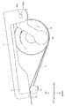
図1は、実施形態に係るプリンタ1について、開閉部3が開放状態である場合を示す斜視図である。図2は、実施形態に係るプリンタ1について、開閉部3が閉鎖状態である場合を示す斜視図である。図3は、実施形態に係るプリンタ1の主要部分についての側面図である。
(1) Printer Configuration A printer according to the first embodiment will be described below with reference to FIGS.
FIG. 1 is a perspective view illustrating a case where the opening /closing unit 3 is in an open state with respect to theprinter 1 according to the embodiment. FIG. 2 is a perspective view illustrating theprinter 1 according to the embodiment when the opening /closing part 3 is in a closed state. FIG. 3 is a side view of the main part of theprinter 1 according to the embodiment.

本実施形態のプリンタ1は、図1および図2に示すように、例えば、扁平な直方体形状に形成された携帯型のラベルプリンタであり、筐体2と、開閉部3と、プラテンローラ5(搬送ローラの一例)と、サーマルヘッド6(印字ヘッドの一例)と、トルク伝達機構10とを備える。  As shown in FIGS. 1 and 2, theprinter 1 of the present embodiment is a portable label printer formed in, for example, a flat rectangular parallelepiped shape, and includes ahousing 2, an opening /closing part 3, and a platen roller 5 ( An example of a conveyance roller), a thermal head 6 (an example of a print head), and atorque transmission mechanism 10 are provided.

以下の説明では、直方体形状のプリンタ1の長辺に沿った方向を前後方向と定義する。このとき、図1に示すように、プラテンローラ5が設けられている側を前方(FR)と定義し、その反対側を後方(RR)と定義する。  In the following description, the direction along the long side of the rectangularparallelepiped printer 1 is defined as the front-rear direction. At this time, as shown in FIG. 1, the side on which theplaten roller 5 is provided is defined as the front (FR), and the opposite side is defined as the rear (RR).

筐体2は、プリンタ1の外形形状に合わせて形成されている。
図1に示すように、開閉部3が開放状態のときには、ロール紙Rの収容部RSに対して外部からアクセス可能となる。収容部RSは、ロール紙Rを収容する空間である。ロール紙Rは、帯状の連続紙P(印字媒体の一例)がロール状に巻回されたロール体である。本実施形態のプリンタ1では、ロール紙Rから連続紙Pが繰り出されて印字が行われる。収容部RSには、連続紙Pが繰り出された後にプラテンローラ5(後述する)に至るまでの搬送経路を形成する空間も含まれる。
なお、連続紙Pが、帯状の台紙と、台紙上に予め決められた間隔毎に仮着された複数枚のラベルとを備えていてもよい。その場合には、例えば連続紙Pの一例であるラベルの連続体を巻回したラベルロールのラベル上に印字が行われる。
Thehousing 2 is formed according to the outer shape of theprinter 1.
As shown in FIG. 1, when the opening /closing part 3 is in the open state, the storage part RS of the roll paper R can be accessed from the outside. The accommodating part RS is a space for accommodating the roll paper R. The roll paper R is a roll body in which a strip-shaped continuous paper P (an example of a print medium) is wound in a roll shape. In theprinter 1 of this embodiment, the continuous paper P is fed out from the roll paper R and printing is performed. The accommodating portion RS includes a space that forms a conveyance path from the continuous paper P to the platen roller 5 (described later) after the continuous paper P is fed out.
Note that the continuous paper P may include a belt-like mount and a plurality of labels temporarily attached to the mount at predetermined intervals. In that case, for example, printing is performed on a label of a label roll around which a continuous body of labels as an example of the continuous paper P is wound.

収容部RS内には一対の用紙ガイド部16R,16L(以下、総称して、あるいは個別に「用紙ガイド部16」と表記することがある。)が載置部4上に設置されている。載置部4は、ロール紙Rを載置する部材であり、その表面は収容部RSの底面を構成している。用紙ガイド部16R,16Lは、それぞれロール紙Rの側面に接触した状態でロール紙Rを回転自在の状態で支持してロール紙Rから繰り出される連続紙の搬送をガイドする部材である。
後述するが、本実施形態のプリンタ1では、収容部RSを閉鎖する方向への開閉部3の移動に伴い(つまり、開閉部3が閉鎖する過程で)、用紙ガイド部16R,16Lはそれぞれロール紙Rの側面に近付く方向に移動し、収容部RSを開放する方向への開閉部3の移動に伴い(つまり、開閉部3を開放させる過程で)、用紙ガイド部16R,16Lはロール紙Rの側面から遠ざかる方向に移動する。
A pair ofpaper guide portions 16R and 16L (hereinafter collectively referred to as “paper guide portion 16” in some cases) are installed on the placement portion 4 in the accommodating portion RS. The placement unit 4 is a member on which the roll paper R is placed, and the surface thereof constitutes the bottom surface of the storage unit RS. Thepaper guide portions 16R and 16L are members that guide the conveyance of the continuous paper fed out from the roll paper R while supporting the roll paper R in a rotatable state in contact with the side surfaces of the roll paper R.
As will be described later, in theprinter 1 according to the present embodiment, thepaper guide portions 16R and 16L are each rolled in accordance with the movement of the opening /closing portion 3 in the direction of closing the housing portion RS (that is, in the process of closing the opening / closing portion 3). Thepaper guide parts 16R and 16L move in the direction approaching the side surface of the paper R, and thepaper guide parts 16R and 16L are rolled paper R in accordance with the movement of the opening and closingpart 3 in the direction to open the accommodating part RS (that is, in the process of opening the opening and closing part 3). Move away from the side.

前述したように、開閉部3は、ロール紙Rを収容部RSに収容し、または収容部RSから取り出すために、開放または閉鎖するカバーである。開閉部3の前方端が筐体2に対して離間および接近する方向に揺動可能なように、開閉部3の後方端が筐体2の後方端部においてシャフト(後述する)によって軸支されている。  As described above, the opening /closing part 3 is a cover that opens or closes in order to accommodate the roll paper R in the accommodating part RS or to remove it from the accommodating part RS. The rear end of the opening /closing part 3 is pivotally supported by a shaft (described later) at the rear end of thehousing 2 so that the front end of the opening / closingpart 3 can swing in a direction away from and approaching thehousing 2. ing.

本実施形態では、開閉部3の揺動軸にトルク伝達機構10が取り付けられている。トルク伝達機構10は、開閉部3の揺動による回転トルクを伝達して、用紙ガイド部16R,16Lの横方向の移動を生じさせるものである。すなわち、開閉部3が開放状態であるときにロール紙Rを載置部4に置いた後に開閉部3を閉鎖状態とした場合、用紙ガイド部16R,16Lが互いに近付く方向に移動してロール紙Rの側面を支持する。
トルク伝達機構10の構成については後述する。
In the present embodiment, thetorque transmission mechanism 10 is attached to the swing shaft of the opening /closing part 3. Thetorque transmission mechanism 10 transmits a rotational torque generated by the swinging of the opening /closing part 3 to cause thepaper guide parts 16R and 16L to move in the lateral direction. That is, when the opening /closing part 3 is closed after the roll paper R is placed on the placement part 4 when the opening /closing part 3 is in the open state, thepaper guide parts 16R, 16L move in a direction approaching each other to roll paper. Supports the side of R.
The configuration of thetorque transmission mechanism 10 will be described later.

図1に示すように、筐体2の先端には、プラテンローラ5が正逆方向に回動自在の状態で軸支されている。プラテンローラ5は、ロール紙Rから繰り出される連続紙Pを搬送する搬送手段であり、連続紙Pの幅方向に沿って延在した状態で形成されている。なお、プラテンローラ5は、ステッピングモータ(図示せず)等に機械的に連結されて駆動される。  As shown in FIG. 1, aplaten roller 5 is pivotally supported at the front end of thehousing 2 in a state in which theplaten roller 5 is rotatable in forward and reverse directions. Theplaten roller 5 is a conveying unit that conveys the continuous paper P fed out from the roll paper R, and is formed in a state of extending along the width direction of the continuous paper P. Theplaten roller 5 is mechanically connected to a stepping motor (not shown) or the like and driven.

なお、開閉部3が閉鎖した状態において開閉部3の上面に、ユーザに対するインタフェースに関連する部品(表示パネル、操作釦等)を設けてもよい。  In addition, in a state where the opening /closing part 3 is closed, components (display panel, operation buttons, etc.) related to the interface to the user may be provided on the upper surface of the opening /closing part 3.

サーマルヘッド6は、例えば、文字、記号、図形またはバーコード等のような情報を、ロール紙Rから繰り出される連続紙P上に印字する印字手段である。図3に示すように、開閉部3が閉鎖状態のときに、サーマルヘッド6の印字面が通紙ルートに向き、かつプラテンローラ5に対向するようにしてサーマルヘッド6が設けられている。サーマルヘッド6の印字面には、通電により発熱する複数の発熱抵抗体(発熱素子)が連続紙Pの幅方向に沿って並んで設置されている。サーマルヘッド6は、サーマルヘッド6に印字信号を伝送する配線基板(図示せず)に接続されている。  The thermal head 6 is a printing unit that prints information such as characters, symbols, figures, barcodes, and the like on the continuous paper P fed out from the roll paper R. As shown in FIG. 3, the thermal head 6 is provided so that the printing surface of the thermal head 6 faces the sheet passing route and faces theplaten roller 5 when the opening /closing portion 3 is closed. On the printing surface of the thermal head 6, a plurality of heating resistors (heating elements) that generate heat when energized are arranged along the width direction of the continuous paper P. The thermal head 6 is connected to a wiring board (not shown) that transmits a print signal to the thermal head 6.

図示されていないが、サーマルヘッド6の裏側にはサーマルヘッド6に対して付勢力を与える付勢部材としてのコイルばねが設けられている。
図3を参照すると、開閉部3が閉鎖され、印字が行われているときには、ロール紙Rから繰り出される連続紙Pがプラテンローラ5によって搬送されつつ、プラテンローラ5とサーマルヘッド6の間で挟持される。このとき、サーマルヘッド6は、上記付勢力によってプラテンローラ5に押し付けられ、それによって印字に適したヘッド圧が生成される。
Although not shown, a coil spring is provided on the back side of the thermal head 6 as a biasing member that applies a biasing force to the thermal head 6.
Referring to FIG. 3, when the opening /closing unit 3 is closed and printing is being performed, the continuous paper P fed from the roll paper R is conveyed by theplaten roller 5 and is sandwiched between theplaten roller 5 and the thermal head 6. Is done. At this time, the thermal head 6 is pressed against theplaten roller 5 by the urging force, thereby generating a head pressure suitable for printing.

ロール紙Rの軸方向の用紙ガイド16R,16Lの円滑な移動のために、図3に示すように、用紙ガイド16R,16Lは、載置部4の表面(つまり、収容部RSの底面)から離間している(要するに、接触していない)ことが好ましい。  For smooth movement of thepaper guides 16R and 16L in the axial direction of the roll paper R, as shown in FIG. 3, thepaper guides 16R and 16L are separated from the surface of the placement unit 4 (that is, the bottom surface of the storage unit RS). It is preferable that they are separated (in short, not in contact).

次に、トルク伝達機構10の構成について、図4〜7を参照して説明する。
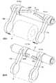
図4は、本実施形態に係るプリンタ1のトルク伝達機構10の分解斜視図である。図5は、本実施形態に係るプリンタ1のトルク伝達機構10と用紙ガイド部16の分解斜視図である。図6は、図5の矢視Aから見た用紙ガイド部16の図である。図7は、本実施形態に係るプリンタ1のトルク伝達機構10の取り付け方法を説明する図である。
Next, the configuration of thetorque transmission mechanism 10 will be described with reference to FIGS.
FIG. 4 is an exploded perspective view of thetorque transmission mechanism 10 of theprinter 1 according to the present embodiment. FIG. 5 is an exploded perspective view of thetorque transmission mechanism 10 and the paper guide unit 16 of theprinter 1 according to the present embodiment. FIG. 6 is a view of the paper guide unit 16 as viewed from the direction of arrow A in FIG. FIG. 7 is a diagram for explaining a method of attaching thetorque transmission mechanism 10 of theprinter 1 according to the present embodiment.

図4において、シャフト12(軸部の一例)は開閉部3の揺動軸となる部材である。シャフト12のシャフト端部120R,120Lは、後述するように、筐体2にシャフト12を取り付けるための面取り加工が施されている。
シャフト12のシャフト端部120R,120Lの近傍において、トルクリミッタ14R,14Lが取り付けられる。トルクリミッタ14R,14Lは、シャフト12の回動によって生ずるトルクを所定値以下に制限する。トルクリミッタ14R,14Lの内輪側部材141R,141Lは、ねじSによってシャフト12に締結されている。トルクリミッタ14R,14Lの外輪側部材142R,142Lは、中空部18hを備えた筒状部材18に回転方向の遊びがないようにして連結される。
In FIG. 4, a shaft 12 (an example of a shaft portion) is a member that becomes a swing shaft of the opening /closing portion 3. Theshaft end portions 120R and 120L of theshaft 12 are chamfered to attach theshaft 12 to thehousing 2 as described later.
Torque limiters 14R and 14L are attached in the vicinity of the shaft ends 120R and 120L of theshaft 12. Thetorque limiters 14R and 14L limit the torque generated by the rotation of theshaft 12 to a predetermined value or less. The innerring side members 141R and 141L of thetorque limiters 14R and 14L are fastened to theshaft 12 by screws S. The outerring side members 142R and 142L of thetorque limiters 14R and 14L are connected to thecylindrical member 18 having thehollow portion 18h so that there is no play in the rotational direction.

図4に示した例では、筒状部材18をトルクリミッタ14R,14Lの外輪側部材142R,142Lに圧入する場合を例示しているが、トルクリミッタ14R,14Lと筒状部材18の取り付け方法はその場合に限られない。図示しないが、例えば、トルクリミッタ14R,14Lの外輪側部材142R,142Lに凸部が設け、筒状部材18には当該凸部に対応する凹部が設けるようにしてもよい。その場合、シャフト12に先ず筒状部材18を通し、その後にトルクリミッタ14R,14Lをシャフト12の両側から差し込み、各トルクリミッタの上記凸部と筒状部材18の上記凹部とを係合させて両者を連結させる。
なお、筒状部材18とトルクリミッタ14R,14Lの外輪側部材142R,142Lとの連結方法は、上述した圧入や係合に限られず、溶着等であってもよい。
In the example shown in FIG. 4, the case where thecylindrical member 18 is press-fitted into the outerring side members 142R and 142L of thetorque limiters 14R and 14L is illustrated. However, the method of attaching thetorque limiters 14R and 14L and thecylindrical member 18 is as follows. It is not limited to that case. Although not shown, for example, the outerring side members 142R and 142L of thetorque limiters 14R and 14L may be provided with a convex portion, and thecylindrical member 18 may be provided with a concave portion corresponding to the convex portion. In that case, thecylindrical member 18 is first passed through theshaft 12, and then thetorque limiters 14R and 14L are inserted from both sides of theshaft 12, and the convex portions of the torque limiters and the concave portions of thecylindrical member 18 are engaged. Connect both.
In addition, the connection method of thecylindrical member 18 and the outerring side members 142R and 142L of thetorque limiters 14R and 14L is not limited to the press-fitting and engagement described above, and may be welding or the like.

図4に示すように、筒状部材18には、用紙ガイド部16R,16Lを筒状部材18の軸方向に移動させるための溝180R,180Lが形成されている。筒状部材18の材質は特に問わないが、用紙ガイド部16R,16Lを円滑に移動させるために、例えば硬質プラスチックからなることが好ましい。  As shown in FIG. 4, grooves 180 </ b> R and 180 </ b> L for moving the paper guide portions 16 </ b> R and 16 </ b> L in the axial direction of thetubular member 18 are formed in thetubular member 18. The material of thecylindrical member 18 is not particularly limited, but is preferably made of, for example, hard plastic in order to smoothly move thepaper guide portions 16R and 16L.

図5に示すように、用紙ガイド部16Lは、円筒部161Lと、主としてロール紙Rの側部を支持する支持部163Lと、円筒部161Lおよび支持部163Lを連結する脚部162Lとを含む。用紙ガイド部16Rは、円筒部161Rと、主としてロール紙Rの側部を支持する支持部163Rと、円筒部161Rおよび支持部163Rを連結する脚部162Rとを含む。図3に示したように、各用紙ガイド部の支持部と脚部はロール紙Rの側部と接触するため、その表面に非粘着加工が施されていることが好ましい。これは以下の理由による。例えば、ロール紙Rが台紙なしラベルの場合、ロール状に巻いたラベルの側面の粘着剤が用紙ガイド部16R,16Lに付着する場合がある。その場合、用紙ガイド部16R,16Lの表面に非粘着加工が施されていないと、ロール紙Rの収容部RS内での円滑な回転を阻害する可能性があるためである。  As shown in FIG. 5, thepaper guide portion 16L includes acylindrical portion 161L, a support portion 163L that mainly supports the side portion of the roll paper R, and aleg portion 162L that connects thecylindrical portion 161L and the support portion 163L. Thepaper guide portion 16R includes acylindrical portion 161R, asupport portion 163R that mainly supports the side portion of the roll paper R, and aleg portion 162R that connects thecylindrical portion 161R and thesupport portion 163R. As shown in FIG. 3, since the support portion and the leg portion of each paper guide portion are in contact with the side portion of the roll paper R, it is preferable that the surface is subjected to non-adhesive processing. This is due to the following reason. For example, when the roll paper R is a label without a base sheet, the adhesive on the side surface of the roll wound label may adhere to thepaper guide portions 16R and 16L. In this case, if the surface of thepaper guide portions 16R and 16L is not subjected to non-adhesive processing, smooth rotation of the roll paper R in the accommodating portion RS may be hindered.

図5に示すように、用紙ガイド部16R,16Lの円筒部161R,161Lに筒状部材18の各端部を挿入するようにして、用紙ガイド部16R,16Lを筒状部材18に連結させる。
図6に示すように、用紙ガイド部16R,16Lの円筒部161R,161Lには、突起161Ra,161Laが形成されている。用紙ガイド部16R,16Lと筒状部材18の連結は、用紙ガイド部16R,16Lの突起161Ra,161Laが、それぞれ筒状部材18の溝180R,180Lに係合するようにして行われる。
用紙ガイド部16R,16Lの円筒部161R,161Lの内径は、筒状部材18の外径よりも僅かに大きく、筒状部材18は、用紙ガイド部16R,16Lの円筒部161R,161L内を滑らかに摺動可能である。
以上説明したようにして、用紙ガイド部16R,16Lは、軸部としてのシャフト12に係合する。
As shown in FIG. 5, thepaper guide portions 16R and 16L are connected to thecylindrical member 18 so that the end portions of thecylindrical member 18 are inserted into thecylindrical portions 161R and 161L of thepaper guide portions 16R and 16L.
As shown in FIG. 6, protrusions 161Ra and 161La are formed on thecylindrical portions 161R and 161L of thepaper guide portions 16R and 16L. Thepaper guide portions 16R, 16L and thetubular member 18 are connected such that the protrusions 161Ra, 161La of thepaper guide portions 16R, 16L are engaged with thegrooves 180R, 180L of thetubular member 18, respectively.
The inner diameters of thecylindrical portions 161R and 161L of thepaper guide portions 16R and 16L are slightly larger than the outer diameter of thecylindrical member 18, and thecylindrical member 18 smoothly moves inside thecylindrical portions 161R and 161L of thepaper guide portions 16R and 16L. Is slidable.
As described above, thepaper guide portions 16R and 16L are engaged with theshaft 12 as the shaft portion.

図7に示すように、シャフト12のシャフト端部120R,120Lは、それぞれ開閉部3のシャフト端固定部31R,31Lのシャフト貫通孔31Ra,31Laに挿入される。シャフト端部120R,120Lの断面形状は、シャフト貫通孔31Ra,31Laの形状と概ね同一形状となっている。シャフト端部120R,120Lは面取り加工が施されているため、シャフト端部120R,120Lがそれぞれシャフト貫通孔31Ra,31Laに挿入された状態では、シャフト12と開閉部3は一体的に回動する。すなわち、開閉部3は、開閉動作時にシャフト12を揺動軸として揺動する。  As shown in FIG. 7, theshaft end portions 120R and 120L of theshaft 12 are inserted into the shaft through holes 31Ra and 31La of the shaftend fixing portions 31R and 31L of the opening /closing portion 3, respectively. The cross-sectional shapes of theshaft end portions 120R and 120L are substantially the same as the shapes of the shaft through holes 31Ra and 31La. Since theshaft end portions 120R and 120L are chamfered, theshaft 12 and the opening /closing portion 3 rotate integrally when theshaft end portions 120R and 120L are inserted into the shaft through holes 31Ra and 31La, respectively. . That is, the opening /closing part 3 swings around theshaft 12 as the swing axis during the opening / closing operation.

(2)トルク伝達機構および用紙ガイド部の動作
次に、図7および図8を参照してトルク伝達機構10および用紙ガイド部16の動作について説明する。
以下の説明では、図7のトルク伝達機構10および用紙ガイド部16の状態において、開閉部3が開放状態である場合を想定する。図8Aおよび図8Bは、開閉部3を開放状態から閉鎖状態にするときのトルク伝達機構10および用紙ガイド部16の動作を順に示している。
(2) Operation of Torque Transmission Mechanism and Paper Guide Part Next, the operation of thetorque transmission mechanism 10 and the paper guide part 16 will be described with reference to FIGS.
In the following description, it is assumed that the opening /closing unit 3 is in the open state in the state of thetorque transmission mechanism 10 and the paper guide unit 16 in FIG. 8A and 8B sequentially show the operations of thetorque transmission mechanism 10 and the paper guide portion 16 when the opening /closing portion 3 is changed from the open state to the closed state.

先ず、図7に示すように、開閉部3が開放状態である場合には、用紙ガイド部16R,16Lがそれぞれ筒状部材18の右側(RH)の端、左側(LH)の端にある。このとき、用紙ガイド部16Rの突起161Raは筒状部材18の溝180Rの右側の端部近傍にあり、用紙ガイド部16Lの突起161Laは筒状部材18の溝180Lの左側の端部近傍にある。  First, as shown in FIG. 7, when the opening /closing part 3 is in the open state, thesheet guide parts 16R and 16L are respectively located on the right (RH) end and the left (LH) end of thecylindrical member 18. At this time, the protrusion 161Ra of thepaper guide portion 16R is in the vicinity of the right end of thegroove 180R of thecylindrical member 18, and the protrusion 161La of thepaper guide portion 16L is in the vicinity of the left end of thegroove 180L of thecylindrical member 18. .

次に、開閉部3が開放状態から閉鎖状態に向けて移動し始めると、それに連動してシャフト12が回転する。シャフト12の回転に連動して、シャフト12に締結されているトルクリミッタ14R,14Lの内輪側部材141R,141Lと、トルクリミッタ14R,14Lの外輪側部材142R,142Lとが回転する。なお、図8Aの状態では、用紙ガイド部16R,16Lがロール紙Rの側面に接触しておらず、トルクリミッタ14R,14Lの外輪側部材142R,142Lに掛かる負荷が高くないため、外輪側部材142R,142Lは内輪側部材141R,141Lと連動して回転する。外輪側部材142R,142Lの回転に連動して、トルクリミッタ14R,14Lの外輪側部材142R,142Lに連結されている筒状部材18も、シャフト12と同じ方向に回転する。その結果、図8Aに示すように、筒状部材18の溝180R,180Lに係合する突起161Ra,161Laが溝内で互いに近付く方向に変位し、それによって用紙ガイド部16R,16Lが互いに近付く方向(図8Aにおいて矢印で示す方向)に移動する。  Next, when the opening /closing part 3 starts to move from the open state to the closed state, theshaft 12 rotates in conjunction therewith. In conjunction with the rotation of theshaft 12, the innerring side members 141R and 141L of thetorque limiters 14R and 14L fastened to theshaft 12 and the outerring side members 142R and 142L of thetorque limiters 14R and 14L rotate. In the state of FIG. 8A, thepaper guide portions 16R and 16L are not in contact with the side surface of the roll paper R, and the load applied to the outerring side members 142R and 142L of thetorque limiters 14R and 14L is not high. 142R and 142L rotate in conjunction with the innerring side members 141R and 141L. In conjunction with the rotation of the outerring side members 142R and 142L, thetubular member 18 connected to the outerring side members 142R and 142L of thetorque limiters 14R and 14L also rotates in the same direction as theshaft 12. As a result, as shown in FIG. 8A, the protrusions 161Ra and 161La engaged with thegrooves 180R and 180L of thecylindrical member 18 are displaced in a direction in which they approach each other in the groove, whereby thepaper guide portions 16R and 16L approach each other. It moves in the direction indicated by the arrow in FIG. 8A.

用紙ガイド部16R,16Lが互いに近付く方向に移動し、図8Bに示すように、用紙ガイド部16R,16Lがロール紙Rの両側面に接触し始めると、トルクリミッタ14R,14Lの外輪側部材142R,142Lに掛かる負荷が増加する。その結果、トルクリミッタ14R,14Lの内輪側部材141R,141Lのトルクが外輪側部材142R,142Lに伝達されなくなり、シャフト12と内輪側部材141R,141Lが空回りする状態となる。その状態に達した後は、用紙ガイド部16R,16Lが移動を停止する。  When thepaper guide portions 16R and 16L move toward each other and thepaper guide portions 16R and 16L start to contact both side surfaces of the roll paper R as shown in FIG. 8B, the outerring side member 142R of thetorque limiters 14R and 14L. , 142L increases. As a result, the torque of the innerring side members 141R and 141L of thetorque limiters 14R and 14L is not transmitted to the outerring side members 142R and 142L, so that theshaft 12 and the innerring side members 141R and 141L are idled. After reaching that state, thepaper guide portions 16R and 16L stop moving.

逆に、開閉部3を閉鎖状態から開放状態にした場合には、トルクリミッタ14R,14Lは動作せず、用紙ガイド部16R,16Lが互いに遠ざかる方向に移動する。  On the contrary, when the opening /closing part 3 is changed from the closed state to the open state, thetorque limiters 14R, 14L do not operate and thepaper guide parts 16R, 16L move away from each other.

以上説明したように、本実施形態のプリンタ1では、シャフト12の回りに取り付けられ、溝が形成された筒状部材18を設けるとともに、筒状部材18の溝に係合する用紙ガイド部16が、開閉部3の揺動による筒状部材18の回転に応じてロール紙Rの軸方向に移動するように構成した。そのため、プリンタ1のユーザは開閉部3を閉じる作業を行うことのみによって自動的に用紙ガイド部16の間隔を調節することができ、用紙ガイド部16自体を調節する作業を行わずに済む。つまり、用紙ガイド部16の調整を行う作業負担を削減することができる。  As described above, in theprinter 1 of the present embodiment, thecylindrical member 18 that is attached around theshaft 12 and has a groove is provided, and the paper guide portion 16 that engages with the groove of thecylindrical member 18 is provided. The roll paper R is configured to move in the axial direction in accordance with the rotation of thecylindrical member 18 caused by the swinging of the opening /closing unit 3. Therefore, the user of theprinter 1 can automatically adjust the interval between the paper guide portions 16 only by performing the operation of closing the opening /closing portion 3, and does not need to perform the operation of adjusting the paper guide portion 16 itself. That is, it is possible to reduce a work load for adjusting the paper guide unit 16.

また、本実施形態のプリンタ1では、筒状部材18は、収容部RSに収容されたロール紙Rの中心軸よりも上方に設けられており、用紙ガイド部16は、筒状部材18から下方に延びている。つまり、用紙ガイド部16は、筒状部材18から載置部4(収容部RSの底面)に対して延伸した形状を有している。そのため、開閉部3を開放させた状態で、プリンタ1の下方の位置(例えば、載置部4)にユーザが手を入れやすく、プリンタ1の洗浄が容易となる利点がある。  Further, in theprinter 1 of the present embodiment, thecylindrical member 18 is provided above the central axis of the roll paper R accommodated in the accommodating portion RS, and the paper guide portion 16 is disposed below thecylindrical member 18. It extends to. That is, the paper guide portion 16 has a shape extending from thetubular member 18 to the placement portion 4 (the bottom surface of the accommodating portion RS). Therefore, there is an advantage that the user can easily put a hand in a position below the printer 1 (for example, the placement unit 4) with the opening /closing unit 3 opened, and theprinter 1 can be easily cleaned.

以上、本発明の実施形態について詳細に説明したが、本発明のプリンタは上記実施形態に限定されず、本発明の主旨を逸脱しない範囲において、種々の改良や変更をしてもよいのは勿論である。
例えば、上述した実施形態では、トルクリミッタ14を設けた場合について説明したが、その限りではない。プリンタ1に使用するロール紙Rの幅が一定である場合には、トルクリミッタ14を設けなくてもよい。その場合には、開閉部3の揺動に伴うシャフト12の回転量と、筒状部材18の溝180R,180Lの中心軸に対する傾斜とを調節することで、開閉部3の揺動に伴う用紙ガイド部16の移動量を、収容対象となるロール紙Rの幅に合わせて決定してもよい。要するに、トルクリミッタ14を設けなくても、幅が異なる様々な種類のロール紙Rに応じて本実施形態のトルク伝達機構10を様々なプリンタに実装することができる。
The embodiment of the present invention has been described in detail above. However, the printer of the present invention is not limited to the above embodiment, and various improvements and modifications may be made without departing from the spirit of the present invention. It is.
For example, in the above-described embodiment, the case where the torque limiter 14 is provided has been described, but the present invention is not limited thereto. When the width of the roll paper R used in theprinter 1 is constant, the torque limiter 14 need not be provided. In that case, by adjusting the rotation amount of theshaft 12 accompanying the swinging of the opening /closing part 3 and the inclination of thecylindrical member 18 with respect to the central axis of thegrooves 180R, 180L, the sheet accompanying the swinging of the opening /closing part 3 is adjusted. The amount of movement of the guide unit 16 may be determined according to the width of the roll paper R to be stored. In short, even if the torque limiter 14 is not provided, thetorque transmission mechanism 10 of the present embodiment can be mounted on various printers according to various types of roll paper R having different widths.

上述した実施形態では、筒状部材18に溝180R,180Lを設け、用紙ガイド部16R,16Lに突起161Ra,161Laを設け、両者が係合する場合について説明したが、その限りではない。逆に、筒状部材18に突起を設け、用紙ガイド部16R,16Lに溝を設け、両者が係合するようにしてもよい。  In the embodiment described above, the case has been described in which thecylindrical member 18 is provided with thegrooves 180R and 180L, thepaper guide portions 16R and 16L are provided with the protrusions 161Ra and 161La, and the both engage with each other. Conversely, protrusions may be provided on thecylindrical member 18 and grooves may be provided on thepaper guide portions 16R and 16L so that both engage.

上述した実施形態では、ロール紙Rの両側面をプリンタ1の中心において左右から支持する一対の用紙ガイド部16R,16Lを設けた場合について説明したが、この限りではない。プリンタの左右のいずれか一方に寄せてロール紙Rを支持するようにしてもよい。その場合には、単一の用紙ガイド部16を設けるとともに、筒状部材には単一方向に延びる溝(例えば、溝180R,180Lのいずれか一方を延伸させた溝)を形成する。  In the above-described embodiment, the case where the pair ofpaper guide portions 16R and 16L that support both side surfaces of the roll paper R from the left and right at the center of theprinter 1 has been described. The roll paper R may be supported close to either the left or right side of the printer. In that case, a single sheet guide portion 16 is provided, and a groove extending in a single direction (for example, a groove formed by extending one of thegrooves 180R and 180L) is formed in the cylindrical member.

上述した実施形態では、本発明の軸部の例として、開閉部3のシャフト端固定部31R,31Lを横断するシャフト12を挙げたが、その限りではなく、仮想的に軸が設定されればよい。例えば、図4において、トルクリミッタ14R,14Lの外輪側部材142R,142Lの間のシャフト12の中央部分は、仮想軸上にトルクリミッタ14および筒状部材18が配置できる限り、省いてもよい。  In the above-described embodiment, theshaft 12 that traverses the shaftend fixing portions 31R and 31L of the opening /closing portion 3 has been described as an example of the shaft portion of the present invention. Good. For example, in FIG. 4, the central portion of theshaft 12 between the outerring side members 142R and 142L of thetorque limiters 14R and 14L may be omitted as long as the torque limiter 14 and thecylindrical member 18 can be disposed on the virtual axis.

上述した実施形態では、図7に示したようにプリンタ1の正面視で見て、溝180R,180Lを筒状部材18の両端部から中央部にかけて斜め上方に形成した場合について説明したが、その場合に限られない。突起161Ra,161Laの位置を調節することで、溝180R,180Lを筒状部材18の両端部から中央部にかけて斜め下方に形成することもできる。  In the above-described embodiment, as illustrated in FIG. 7, the case where the grooves 180 </ b> R and 180 </ b> L are formed obliquely upward from both end portions to the central portion of theprinter 1 when viewed from the front is described. Not limited to cases. By adjusting the positions of the protrusions 161Ra and 161La, thegrooves 180R and 180L can be formed obliquely downward from both ends of thecylindrical member 18 to the center.

上述した実施形態では、揺動部の一例として、サーマルヘッド6を備えた開閉部3を挙げたが、その限りではない。他のプリンタの例として、プラテンローラを備えた開閉部を有するプリンタであってもよい。その場合には、図1のプラテンローラ5の位置にサーマルヘッド6が設けられる。
また、用紙ガイド部を移動させる揺動部は、プラテンローラやサーマルヘッドを備えていない開閉部であってもよい。例えば、第1の開閉部と、例えばサーマルヘッドを備えた第2の開閉部とが連動して動作して、ロール紙の収容部を開閉するプリンタの場合、第1の開閉部に連動して用紙ガイド部が移動するようにしてもよいし、第2の開閉部に連動して用紙ガイド部が移動するようにしてもよい。
In the above-described embodiment, the opening /closing unit 3 including the thermal head 6 is described as an example of the swinging unit, but the present invention is not limited thereto. As another example of the printer, a printer having an opening / closing unit including a platen roller may be used. In that case, the thermal head 6 is provided at the position of theplaten roller 5 in FIG.
Further, the swinging portion that moves the paper guide portion may be an opening / closing portion that does not include a platen roller or a thermal head. For example, in the case of a printer that operates in conjunction with a first opening / closing section and a second opening / closing section having a thermal head, for example, to open and close the roll paper storage section, the printer operates in conjunction with the first opening / closing section. The paper guide portion may be moved, or the paper guide portion may be moved in conjunction with the second opening / closing portion.

上述した実施形態では、サーマルヘッドを有する感熱式のプリンタを例として説明したが、その限りではない。本発明は印字方式とは無関係に適用可能であり、他の印字方式のプリンタに適用することができる。本発明は例えばインクリボンを用いた熱転写方式のプリンタに適用してもよい。その場合、カバーを閉じることでインクリボンを供給するインクリボン供給部の両側面をガイドするようにしてもよい。  In the above-described embodiment, a thermal printer having a thermal head has been described as an example. However, the present invention is not limited to this. The present invention can be applied regardless of the printing method, and can be applied to printers of other printing methods. The present invention may be applied to, for example, a thermal transfer printer using an ink ribbon. In that case, you may make it guide the both sides | surfaces of the ink ribbon supply part which supplies an ink ribbon by closing a cover.

上述した実施形態では、シャフト12と、筒状部材18と、用紙ガイド部16の円筒部161とが同軸である場合について説明したが、その限りではない。例えば、シャフト12の中心軸が、筒状部材18および用紙ガイド部16の円筒部161の中心軸と異なっていてもよく、その場合には両軸をギアあるいはベルトで連結して動作させてもよい。  In the embodiment described above, the case where theshaft 12, thecylindrical member 18, and the cylindrical portion 161 of the paper guide portion 16 are coaxial has been described. For example, the center axis of theshaft 12 may be different from the center axis of thecylindrical member 18 and the cylindrical portion 161 of the paper guide portion 16, and in this case, both shafts may be connected by a gear or a belt to operate. Good.

上述した実施形態において、トルク伝達機構10は、開閉部3の揺動に伴うシャフト12の回転トルクを、用紙ガイド部16の、ロール紙Rの軸方向に変位させる力に伝達するものであるが、その限りではない。シャフト12の回転トルクによって、用紙ガイド部16を移動させるのみならず、他のガイド部材を移動させるようにしてもよい。つまり、開閉部3の揺動によって複数のガイド部材を移動させるようにしてもよい。例えば、ロール紙Rから繰り出された連続紙Pを用紙通路の下流側でガイドする場合には、シャフト12のトルクをギアまたはベルトによって前方へ伝達し、追加のシャフトを回転させることで追加の用紙ガイド部を移動させるように構成してもよい。  In the embodiment described above, thetorque transmission mechanism 10 transmits the rotational torque of theshaft 12 accompanying the swing of the opening /closing unit 3 to the force of the paper guide unit 16 that displaces in the axial direction of the roll paper R. That is not the case. Not only the paper guide portion 16 is moved by the rotational torque of theshaft 12, but also other guide members may be moved. That is, the plurality of guide members may be moved by swinging the opening /closing part 3. For example, when the continuous paper P fed out from the roll paper R is guided on the downstream side of the paper path, the torque of theshaft 12 is transmitted forward by a gear or a belt, and the additional shaft is rotated to rotate the additional paper. You may comprise so that a guide part may be moved.

上述した実施形態では、シャフト12の両端に2個のトルクリミッタ14R,14Lを設ける場合について説明したが、それに限られない。用紙ガイド16R,16Lは互いに連動して移動するため、トルクリミッタ14R,14Lの少なくともいずれか一方のトルクリミッタが取り付けられていればよい。  In the above-described embodiment, the case where the twotorque limiters 14R and 14L are provided at both ends of theshaft 12 has been described, but the present invention is not limited thereto. Since the paper guides 16R and 16L move in conjunction with each other, it is sufficient that at least one of thetorque limiters 14R and 14L is attached.

1…プリンタ
2…筐体
3…開閉部
31R,31L…シャフト端固定部
31Ra,31La…シャフト貫通孔
4…載置部
5…プラテンローラ
6…サーマルヘッド
16R,16L…用紙ガイド部
161R,161L…円筒部
161Ra,161La…突起
162R,162L…脚部
163R,163L…支持部
10…トルク伝達機構
12…シャフト
120R,120L…シャフト端部
14R,14L…トルクリミッタ
18…筒状部材
18h…中空部
180R,180L…溝
RS…収容部
R…ロール紙
DESCRIPTION OFSYMBOLS 1 ...Printer 2 ... Housing | casing 3 ... Opening / closingpart 31R, 31L ... Shaft end fixing | fixed part 31Ra, 31La ... Shaft through-hole 4 ... Mountingpart 5 ... Platen roller 6 ...Thermal head 16R, 16L ...Paper guide part 161R, 161L ... Cylindrical parts 161Ra, 161La ...projections 162R, 162L ...leg parts 163R, 163L ... supportpart 10 ...torque transmission mechanism 12 ...shaft 120R, 120L ...shaft end parts 14R, 14L ...torque limiter 18 ...cylindrical member 18h ...hollow part 180R , 180L ... groove RS ... housing part R ... roll

Claims (8)

Translated fromJapanese
印字媒体を収容する収容部と、
軸部を支点として揺動可能な揺動部と、
前記軸部に係合し、前記揺動部の揺動によって前記収容部に収容される前記印字媒体の幅方向に移動するガイド部と、を有するプリンタ。
An accommodating portion for accommodating a print medium;
A swinging portion that can swing about a shaft as a fulcrum;
And a guide portion that engages with the shaft portion and moves in a width direction of the print medium accommodated in the accommodation portion by the oscillation of the oscillation portion.
前記揺動部は、前記収容部を開放又は閉鎖する開閉部を含む、請求項1に記載されたプリンタ。  The printer according to claim 1, wherein the swinging unit includes an opening / closing unit that opens or closes the housing unit. 前記ガイド部は、前記収容部の底面から離間している、請求項1又は2に記載されたプリンタ。  The printer according to claim 1, wherein the guide portion is separated from a bottom surface of the housing portion. 前記ガイド部は、前記軸部から前記収容部の底面に対して延伸した形状を有する、請求項1〜3のいずれかに記載されたプリンタ。  The printer according to claim 1, wherein the guide part has a shape extending from the shaft part to a bottom surface of the housing part. 前記軸部の回動によって生じるトルクを所定値以下に制限するトルクリミッタを有する、請求項1〜4のいずれかに記載されたプリンタ。  The printer according to claim 1, further comprising a torque limiter that limits a torque generated by the rotation of the shaft portion to a predetermined value or less. 前記ガイド部は、
前記収容部を閉鎖する方向への前記開閉部の移動に伴い、前記印刷媒体の側面に近づく方向に移動し、前記収容部を開放する方向への前記開閉部の移動に伴い、前記印刷媒体の側面から遠ざかる方向に移動する、請求項2に記載されたプリンタ。
The guide portion is
Along with the movement of the opening / closing part in the direction of closing the storage part, the movement of the printing medium moves in a direction approaching the side surface of the print medium, and with the movement of the opening / closing part in a direction of opening the storage part. The printer according to claim 2, wherein the printer moves in a direction away from the side surface.
前記印字媒体は、ロール状に巻回されたロール体の形態である、請求項1〜6のいずれかに記載されたプリンタ。  The printer according to claim 1, wherein the print medium is in the form of a roll body wound in a roll shape. 前記揺動部は、前記印字媒体を搬送する搬送ローラ、又は前記印字媒体に印字する印字ヘッドを有する、請求項1〜7のいずれかに記載されたプリンタ。  The printer according to claim 1, wherein the swinging unit includes a transport roller that transports the print medium or a print head that prints on the print medium.
JP2016115132A2016-06-092016-06-09 PrinterActiveJP6872859B2 (en)

Priority Applications (1)

Application NumberPriority DateFiling DateTitle
JP2016115132AJP6872859B2 (en)2016-06-092016-06-09 Printer

Applications Claiming Priority (1)

Application NumberPriority DateFiling DateTitle
JP2016115132AJP6872859B2 (en)2016-06-092016-06-09 Printer

Publications (2)

Publication NumberPublication Date
JP2017217862Atrue JP2017217862A (en)2017-12-14
JP6872859B2 JP6872859B2 (en)2021-05-19

Family

ID=60657177

Family Applications (1)

Application NumberTitlePriority DateFiling Date
JP2016115132AActiveJP6872859B2 (en)2016-06-092016-06-09 Printer

Country Status (1)

CountryLink
JP (1)JP6872859B2 (en)

Cited By (2)

* Cited by examiner, † Cited by third party
Publication numberPriority datePublication dateAssigneeTitle
JP2020075810A (en)*2018-11-092020-05-21フクダ電子株式会社recorder
US20230406017A1 (en)*2020-11-182023-12-21Sato Holdings Kabushiki KaishaPrinter

Citations (5)

* Cited by examiner, † Cited by third party
Publication numberPriority datePublication dateAssigneeTitle
JP2002128331A (en)*2000-10-272002-05-09Noritsu Koki Co Ltd Print media support device
JP2002154725A (en)*2000-11-172002-05-28Noritsu Koki Co Ltd Inkjet printer
JP2003176041A (en)*2001-12-072003-06-24Brother Ind Ltd Printing equipment
US20120183342A1 (en)*2011-01-142012-07-19Primax Electronics Ltd.Paper roll fixing device of printer
JP2015229257A (en)*2014-06-042015-12-21サトーホールディングス株式会社 Printer

Patent Citations (5)

* Cited by examiner, † Cited by third party
Publication numberPriority datePublication dateAssigneeTitle
JP2002128331A (en)*2000-10-272002-05-09Noritsu Koki Co Ltd Print media support device
JP2002154725A (en)*2000-11-172002-05-28Noritsu Koki Co Ltd Inkjet printer
JP2003176041A (en)*2001-12-072003-06-24Brother Ind Ltd Printing equipment
US20120183342A1 (en)*2011-01-142012-07-19Primax Electronics Ltd.Paper roll fixing device of printer
JP2015229257A (en)*2014-06-042015-12-21サトーホールディングス株式会社 Printer

Cited By (4)

* Cited by examiner, † Cited by third party
Publication numberPriority datePublication dateAssigneeTitle
JP2020075810A (en)*2018-11-092020-05-21フクダ電子株式会社recorder
JP7166146B2 (en)2018-11-092022-11-07フクダ電子株式会社 recorder
US20230406017A1 (en)*2020-11-182023-12-21Sato Holdings Kabushiki KaishaPrinter
US12202283B2 (en)*2020-11-182025-01-21Sato Holdings Kabushiki KaishaPrinter

Also Published As

Publication numberPublication date
JP6872859B2 (en)2021-05-19

Similar Documents

PublicationPublication DateTitle
JP3687912B2 (en) Printer unit
JP2005305732A (en)Printer
JP2013052612A (en)Printer
JP2004106489A (en) Rotary cutter device and printer
JP2017217862A (en)Printer
JP2008120068A (en) Thermal printer unit
JP4285545B2 (en) Image forming apparatus
JP3849934B2 (en) Printer
JP4727292B2 (en) Thermal printer
JP6756523B2 (en) Printer
JP3127780U (en) Image forming apparatus
JP3738648B2 (en) Recording device
JP2533530Y2 (en) Thermal printer
JP5286401B2 (en) Label printer
JP2004114302A (en) Printer
JP3779607B2 (en) Thermal transfer printer
JP4085569B2 (en) Assembly structure of flexible bush and recording apparatus provided with this assembly structure
JP2002187301A (en) Angle adjustment method and angle adjustment structure of heating element of printing apparatus
JP6772523B2 (en) Carriage structure and printing equipment
JP5266726B2 (en) Image forming apparatus
JPH09277647A (en)Thermal printer
JPS59179380A (en) Carriage feed pulley holding structure
JP2024078482A (en) Image Recording Device
JP3937176B2 (en) Thermal transfer printer
JP5153946B2 (en) Thermal printer unit

Legal Events

DateCodeTitleDescription
A621Written request for application examination

Free format text:JAPANESE INTERMEDIATE CODE: A621

Effective date:20190325

RD02Notification of acceptance of power of attorney

Free format text:JAPANESE INTERMEDIATE CODE: A7422

Effective date:20200109

A977Report on retrieval

Free format text:JAPANESE INTERMEDIATE CODE: A971007

Effective date:20200122

A131Notification of reasons for refusal

Free format text:JAPANESE INTERMEDIATE CODE: A131

Effective date:20200128

A521Request for written amendment filed

Free format text:JAPANESE INTERMEDIATE CODE: A523

Effective date:20200327

A131Notification of reasons for refusal

Free format text:JAPANESE INTERMEDIATE CODE: A131

Effective date:20200915

A521Request for written amendment filed

Free format text:JAPANESE INTERMEDIATE CODE: A523

Effective date:20201106

TRDDDecision of grant or rejection written
A01Written decision to grant a patent or to grant a registration (utility model)

Free format text:JAPANESE INTERMEDIATE CODE: A01

Effective date:20210406

A61First payment of annual fees (during grant procedure)

Free format text:JAPANESE INTERMEDIATE CODE: A61

Effective date:20210420

R150Certificate of patent or registration of utility model

Ref document number:6872859

Country of ref document:JP

Free format text:JAPANESE INTERMEDIATE CODE: R150

R250Receipt of annual fees

Free format text:JAPANESE INTERMEDIATE CODE: R250

R250Receipt of annual fees

Free format text:JAPANESE INTERMEDIATE CODE: R250


[8]ページ先頭

©2009-2025 Movatter.jp