JP2017213040A - Biological information acquisition apparatus and biological information acquisition method - Google Patents
Biological information acquisition apparatus and biological information acquisition methodDownload PDFInfo
- Publication number
- JP2017213040A JP2017213040AJP2016107006AJP2016107006AJP2017213040AJP 2017213040 AJP2017213040 AJP 2017213040AJP 2016107006 AJP2016107006 AJP 2016107006AJP 2016107006 AJP2016107006 AJP 2016107006AJP 2017213040 AJP2017213040 AJP 2017213040A
- Authority
- JP
- Japan
- Prior art keywords
- light
- light emitting
- biological information
- information acquisition
- unit
- Prior art date
- Legal status (The legal status is an assumption and is not a legal conclusion. Google has not performed a legal analysis and makes no representation as to the accuracy of the status listed.)
- Pending
Links
- 238000000034methodMethods0.000titleclaimsabstractdescription32
- 210000004204blood vesselAnatomy0.000claimsdescription180
- 239000008280bloodSubstances0.000claimsdescription64
- 210000004369bloodAnatomy0.000claimsdescription63
- WQZGKKKJIJFFOK-GASJEMHNSA-NGlucoseNatural productsOC[C@H]1OC(O)[C@H](O)[C@@H](O)[C@@H]1OWQZGKKKJIJFFOK-GASJEMHNSA-N0.000claimsdescription42
- 239000008103glucoseSubstances0.000claimsdescription42
- QVGXLLKOCUKJST-UHFFFAOYSA-Natomic oxygenChemical compound[O]QVGXLLKOCUKJST-UHFFFAOYSA-N0.000claimsdescription9
- 229910052760oxygenInorganic materials0.000claimsdescription9
- 239000001301oxygenSubstances0.000claimsdescription9
- 238000005259measurementMethods0.000abstractdescription129
- 230000006866deteriorationEffects0.000abstractdescription13
- 238000010586diagramMethods0.000description32
- 238000000862absorption spectrumMethods0.000description29
- 238000004364calculation methodMethods0.000description14
- 238000004891communicationMethods0.000description14
- 238000002834transmittanceMethods0.000description11
- 238000012986modificationMethods0.000description10
- 230000004048modificationEffects0.000description10
- 230000008569processEffects0.000description9
- 239000000306componentSubstances0.000description8
- 230000020169heat generationEffects0.000description8
- 238000003384imaging methodMethods0.000description7
- 210000001519tissueAnatomy0.000description7
- 230000000052comparative effectEffects0.000description6
- 210000003462veinAnatomy0.000description6
- 238000012545processingMethods0.000description5
- 102000001554HemoglobinsHuman genes0.000description3
- 108010054147HemoglobinsProteins0.000description3
- 238000002835absorbanceMethods0.000description3
- 238000004458analytical methodMethods0.000description3
- 239000012503blood componentSubstances0.000description3
- 230000000694effectsEffects0.000description3
- 230000009477glass transitionEffects0.000description3
- 230000003287optical effectEffects0.000description3
- 230000002792vascularEffects0.000description3
- 238000012935AveragingMethods0.000description2
- 206010037660PyrexiaDiseases0.000description2
- 230000008901benefitEffects0.000description2
- 238000004590computer programMethods0.000description2
- 230000005484gravityEffects0.000description2
- 230000001678irradiating effectEffects0.000description2
- 230000031700light absorptionEffects0.000description2
- 238000004519manufacturing processMethods0.000description2
- 230000003595spectral effectEffects0.000description2
- 240000005561Musa balbisianaSpecies0.000description1
- 235000018290Musa x paradisiacaNutrition0.000description1
- 208000000453Skin NeoplasmsDiseases0.000description1
- 210000000577adipose tissueAnatomy0.000description1
- 238000011088calibration curveMethods0.000description1
- 230000000295complement effectEffects0.000description1
- 239000000470constituentSubstances0.000description1
- 238000001514detection methodMethods0.000description1
- 238000005516engineering processMethods0.000description1
- 210000003743erythrocyteAnatomy0.000description1
- 238000002474experimental methodMethods0.000description1
- 125000002791glucosyl groupChemical groupC1([C@H](O)[C@@H](O)[C@H](O)[C@H](O1)CO)*0.000description1
- 238000005338heat storageMethods0.000description1
- 238000012880independent component analysisMethods0.000description1
- 238000010030laminatingMethods0.000description1
- 239000004973liquid crystal related substanceSubstances0.000description1
- 239000011159matrix materialSubstances0.000description1
- 229910044991metal oxideInorganic materials0.000description1
- 150000004706metal oxidesChemical class0.000description1
- 239000011368organic materialSubstances0.000description1
- 238000010238partial least squares regressionMethods0.000description1
- 230000035699permeabilityEffects0.000description1
- 238000005375photometryMethods0.000description1
- 238000012628principal component regressionMethods0.000description1
- 210000001747pupilAnatomy0.000description1
- 238000000611regression analysisMethods0.000description1
- 238000010187selection methodMethods0.000description1
- 239000004065semiconductorSubstances0.000description1
- 230000035945sensitivityEffects0.000description1
- 201000000849skin cancerDiseases0.000description1
- 230000005236sound signalEffects0.000description1
- 238000007920subcutaneous administrationMethods0.000description1
- 239000000126substanceSubstances0.000description1
- 210000000707wristAnatomy0.000description1
Images


Classifications
- A—HUMAN NECESSITIES
- A61—MEDICAL OR VETERINARY SCIENCE; HYGIENE
- A61B—DIAGNOSIS; SURGERY; IDENTIFICATION
- A61B5/00—Measuring for diagnostic purposes; Identification of persons
- A61B5/145—Measuring characteristics of blood in vivo, e.g. gas concentration or pH-value ; Measuring characteristics of body fluids or tissues, e.g. interstitial fluid or cerebral tissue
- A61B5/14532—Measuring characteristics of blood in vivo, e.g. gas concentration or pH-value ; Measuring characteristics of body fluids or tissues, e.g. interstitial fluid or cerebral tissue for measuring glucose, e.g. by tissue impedance measurement
- A—HUMAN NECESSITIES
- A61—MEDICAL OR VETERINARY SCIENCE; HYGIENE
- A61B—DIAGNOSIS; SURGERY; IDENTIFICATION
- A61B5/00—Measuring for diagnostic purposes; Identification of persons
- A61B5/145—Measuring characteristics of blood in vivo, e.g. gas concentration or pH-value ; Measuring characteristics of body fluids or tissues, e.g. interstitial fluid or cerebral tissue
- A61B5/1455—Measuring characteristics of blood in vivo, e.g. gas concentration or pH-value ; Measuring characteristics of body fluids or tissues, e.g. interstitial fluid or cerebral tissue using optical sensors, e.g. spectral photometrical oximeters
- A61B5/14551—Measuring characteristics of blood in vivo, e.g. gas concentration or pH-value ; Measuring characteristics of body fluids or tissues, e.g. interstitial fluid or cerebral tissue using optical sensors, e.g. spectral photometrical oximeters for measuring blood gases
- A61B5/14552—Details of sensors specially adapted therefor
- A—HUMAN NECESSITIES
- A61—MEDICAL OR VETERINARY SCIENCE; HYGIENE
- A61B—DIAGNOSIS; SURGERY; IDENTIFICATION
- A61B5/00—Measuring for diagnostic purposes; Identification of persons
- A61B5/68—Arrangements of detecting, measuring or recording means, e.g. sensors, in relation to patient
- A61B5/6801—Arrangements of detecting, measuring or recording means, e.g. sensors, in relation to patient specially adapted to be attached to or worn on the body surface
- A61B5/6802—Sensor mounted on worn items
- A61B5/681—Wristwatch-type devices
- A—HUMAN NECESSITIES
- A61—MEDICAL OR VETERINARY SCIENCE; HYGIENE
- A61B—DIAGNOSIS; SURGERY; IDENTIFICATION
- A61B2562/00—Details of sensors; Constructional details of sensor housings or probes; Accessories for sensors
- A61B2562/04—Arrangements of multiple sensors of the same type
- A61B2562/046—Arrangements of multiple sensors of the same type in a matrix array
Landscapes
- Health & Medical Sciences (AREA)
- Life Sciences & Earth Sciences (AREA)
- Physics & Mathematics (AREA)
- Biomedical Technology (AREA)
- Medical Informatics (AREA)
- Biophysics (AREA)
- Pathology (AREA)
- Engineering & Computer Science (AREA)
- Veterinary Medicine (AREA)
- Heart & Thoracic Surgery (AREA)
- Public Health (AREA)
- Molecular Biology (AREA)
- Surgery (AREA)
- Animal Behavior & Ethology (AREA)
- General Health & Medical Sciences (AREA)
- Optics & Photonics (AREA)
- Spectroscopy & Molecular Physics (AREA)
- Emergency Medicine (AREA)
- Measurement Of The Respiration, Hearing Ability, Form, And Blood Characteristics Of Living Organisms (AREA)
Abstract
Translated fromJapaneseDescription
Translated fromJapanese本発明は、生体情報取得装置及び生体情報取得方法に関する。 The present invention relates to a biological information acquisition apparatus and a biological information acquisition method.
従来、血管や血管中の血液に関する生体情報を取得する生体情報取得装置が知られている(例えば、特許文献1)。特許文献1には、生体中の血液成分を測定するために、複数の発光素子を一斉に発光させることにより光量を確保する技術が記載されている。 Conventionally, a biological information acquisition device that acquires biological information related to blood vessels and blood in blood vessels is known (for example, Patent Document 1). Patent Document 1 describes a technique for securing a light amount by simultaneously emitting light from a plurality of light emitting elements in order to measure blood components in a living body.
しかし、複数の発光素子を一斉に発光させる場合、発光させた発光素子が発熱することにより、発光素子が劣化する虞がある。面状に配置された発光素子を一斉に発光させる場合、発光させた複数の発光素子のうち、中央付近に存在する発光素子の放熱が特に困難であり、このような発光素子が劣化しやすい傾向にある。このため、発光素子の劣化を抑制する技術が望まれていた。 However, in the case where a plurality of light emitting elements emit light all at once, there is a possibility that the light emitting elements deteriorate due to the generated light emitting elements generating heat. When emitting light emitting elements arranged in a plane at the same time, it is particularly difficult to dissipate the light emitting elements present near the center among the plurality of emitted light emitting elements, and such light emitting elements tend to deteriorate. It is in. For this reason, the technique which suppresses deterioration of a light emitting element was desired.
本発明は、上述の課題の少なくとも一部を解決するためになされたものであり、以下の形態または適用例として実現することが可能である。 SUMMARY An advantage of some aspects of the invention is to solve at least a part of the problems described above, and the invention can be implemented as the following forms or application examples.
(1)本発明の第1の形態によれば、生体情報取得装置が提供される。この複数の発光素子により形成されており、生体へ光を照射する発光部と、前記生体を透過した光を受光する受光部と、前記発光部と前記受光部とを制御する制御部と、を備え、前記制御部は、前記発光部から照射させた光を、前記受光部に受光させることにより受光結果を取得し、前記受光結果を用いて、生体情報を取得する、生体情報取得装置であって、一回分の前記受光結果の取得のための、前記発光部からの光の照射は、前記複数の発光素子のうち、発光している発光素子と発光していない発光素子とを含む複数の発光パターンを切り替えながら行われる。
本実施形態の生体情報取得装置によれば、一回分の受光結果の取得のための、発光部からの光の照射は、複数の発光素子のうち、発光している発光素子と発光していない発光素子とを含む複数の発光パターンを切り替えながら行われるため、発光素子の連続発光を抑制し、発光素子の発熱に起因する劣化を抑制できる。(1) According to the first aspect of the present invention, a biological information acquisition apparatus is provided. A light emitting unit that is formed of the plurality of light emitting elements, irradiates light to the living body, a light receiving unit that receives light transmitted through the living body, and a control unit that controls the light emitting unit and the light receiving unit. And the control unit is a biological information acquisition device that acquires the light reception result by causing the light receiving unit to receive the light emitted from the light emitting unit, and acquires biological information using the light reception result. The irradiation of light from the light emitting unit for obtaining the light reception result for one time includes a plurality of light emitting elements that emit light and light emitting elements that do not emit light among the plurality of light emitting elements. This is performed while switching the light emission pattern.
According to the biometric information acquisition apparatus of this embodiment, the light irradiation from the light emitting unit for acquiring the light reception result for one time does not emit light from the light emitting elements that emit light among the plurality of light emitting elements. Since it is performed while switching a plurality of light emission patterns including the light emitting element, it is possible to suppress continuous light emission of the light emitting element and suppress deterioration due to heat generation of the light emitting element.
(2)上記生体情報取得装置において、前記発光部を複数備え、前記制御部は、前記複数の発光部の少なくとも一つを発光させることにより前記生体の血管の位置を特定し、前記複数の発光部のうち、前記血管の位置に基づいて、前記一回分の前記受光結果の取得のための、前記発光部からの光の照射を行ってもよい。
本実施形態の生体情報取得装置によれば、血管の位置に基づいて一回分の受光結果の取得のための発光部からの光の照射を行うことにより、血管に関連した生体情報を取得するのに適した発光部を測定用発光部として選択できるため、血管に関連した生体情報を精度良く取得することができる。(2) The biometric information acquisition apparatus includes a plurality of the light emitting units, and the control unit identifies a position of a blood vessel of the living body by causing at least one of the plurality of light emitting units to emit light, and the plurality of light emitting units. Based on the position of the blood vessel in the unit, the light from the light emitting unit may be irradiated for acquiring the light reception result for one time.
According to the biological information acquisition device of the present embodiment, the biological information related to the blood vessel is acquired by irradiating light from the light emitting unit for acquiring the light reception result for one time based on the position of the blood vessel. Since the light emitting unit suitable for the measurement can be selected as the measurement light emitting unit, biological information related to the blood vessel can be obtained with high accuracy.
(3)上記生体情報取得装置において、前記一回分の前記受光結果の取得のための、前記発光部からの光の照射において、前記複数の発光パターンの各発光パターンがいずれも同じ回数だけ繰り返されてもよい。
本実施形態の生体情報取得装置によれば、複数の発光パターンがいずれも同じ回数だけ繰り返されることにより、各発光パターンにおける発光素子の発光位置の偏りを軽減することができるため、血管に関連した生体情報を精度良く取得することができる。(3) In the biometric information acquisition apparatus, each light emission pattern of the plurality of light emission patterns is repeated the same number of times in the irradiation of light from the light emitting unit for obtaining the light reception result for one time. May be.
According to the biometric information acquisition apparatus of this embodiment, since the plurality of light emission patterns are all repeated the same number of times, it is possible to reduce the bias of the light emission position of the light emitting element in each light emission pattern, and thus related to blood vessels. Biological information can be acquired with high accuracy.
(4)上記生体情報取得装置において、前記複数の発光パターンの各発光パターンにて発光している発光素子は、前記発光部の中心に対して点対称又は前記中心を通る線に対して線対称となる位置となってもよい。
本実施形態の生体情報取得装置によれば、発光パターン間における光量のばらつきを抑制でき、この結果として、血管に関連した生体情報を精度良く取得することができる。(4) In the biological information acquiring apparatus, the light emitting elements emitting light in the light emission patterns of the plurality of light emission patterns are point symmetric with respect to the center of the light emitting unit or line symmetric with respect to a line passing through the center. It may be a position.
According to the biological information acquisition apparatus of the present embodiment, variation in the amount of light between the light emission patterns can be suppressed, and as a result, biological information related to blood vessels can be acquired with high accuracy.
(5)上記生体情報取得装置では、前記複数の発光パターンの各発光パターンにおいて、発光している発光素子と隣接する発光素子の中で、発光していない発光素子が存在してもよい。
本実施形態の生体情報取得装置によれば、発光している発光素子が発する熱が周囲に存在する発光していない発光素子の存在する方向へ拡散することにより放熱することができるため、発光素子の発熱に起因する劣化を抑制できる。(5) In the biometric information acquisition apparatus, in each light emission pattern of the plurality of light emission patterns, there may be a light emitting element that does not emit light among light emitting elements adjacent to the light emitting element that emits light.
According to the biological information acquisition device of the present embodiment, the heat generated by the light emitting element that emits light can be dissipated by diffusing in the direction in which the light emitting element that does not emit light exists in the surrounding area, and thus the light emitting element It is possible to suppress deterioration due to heat generation.
(6)上記生体情報取得装置では、前記複数の発光パターンにおいて、任意の発光パターンにおいて発光した発光素子は、当該発光パターンの次の発光パターンにおいて発光しなくてもよい。
本実施形態の生体情報取得装置によれば、発光素子の発熱に起因する劣化を抑制できる。(6) In the biometric information acquisition device, in the plurality of light emission patterns, a light emitting element that emits light in an arbitrary light emission pattern may not emit light in a light emission pattern subsequent to the light emission pattern.
According to the biometric information acquisition apparatus of the present embodiment, it is possible to suppress deterioration due to heat generation of the light emitting element.
(7)上記生体情報取得装置において、前記発光部は、波長が0.7μmから2.5μmの近赤外線を含む光を照射してもよい。
本実施形態の生体情報取得装置によれば、生体を透過しやすい光である近赤外線を用いて生体情報を取得できる。(7) In the biological information acquisition apparatus, the light emitting unit may irradiate light including near infrared light having a wavelength of 0.7 μm to 2.5 μm.
According to the biological information acquisition apparatus of this embodiment, biological information can be acquired using near infrared rays, which are light that easily passes through the living body.
(8)上記生体情報取得装置では、前記複数の発光パターンにおいて、所定数以上の発光素子が発光していてもよい。
所定数より少ない発光素子を発光させる場合と比較して、本実施形態の生体情報取得装置は、十分な発光強度を得ることができる。(8) In the biological information acquisition apparatus, a predetermined number or more of light emitting elements may emit light in the plurality of light emitting patterns.
Compared with the case where fewer than a predetermined number of light emitting elements emit light, the biological information acquisition apparatus of the present embodiment can obtain sufficient light emission intensity.
(9)上記生体情報取得装置において、前記生体情報は、前記生体の血液中のグルコース濃度を含んでもよい。
本実施形態の生体情報取得装置によれば、生体の血液中のグルコース濃度を取得することができる。(9) In the biological information acquisition apparatus, the biological information may include a glucose concentration in blood of the biological body.
According to the biological information acquisition apparatus of the present embodiment, the glucose concentration in the blood of the biological body can be acquired.
(10)上記生体情報取得装置において、前記生体の血液中の酸素飽和度を含んでもよい。
本実施形態の生体情報取得装置によれば、生体の血液中の酸素飽和度を取得することができる。(10) The biometric information acquisition apparatus may include oxygen saturation in the blood of the living body.
According to the biological information acquisition apparatus of the present embodiment, it is possible to acquire the oxygen saturation in the blood of the biological body.
(11)上記生体情報取得装置において、前記発光素子として、OLEDを用いてもよい。
本実施形態の生体情報取得装置によれば、OLEDを用いることができる。(11) In the biological information acquisition apparatus, an OLED may be used as the light emitting element.
According to the biological information acquisition apparatus of this embodiment, an OLED can be used.
本発明は、上述した形態以外の種々の形態でも実現可能であり、例えば、複数の発光素子により形成されており、前記生体へ光を照射する発光部と、前記生体を透過した光を受光する受光部と、を備える生体情報取得装置により生体情報を取得する生体情報取得方法や、この方法を実現するコンピュータープログラム、及び、コンピュータープログラムを格納する一時的でない記録媒体(non-transitory storage medium)等の形態等で実現することが可能である。 The present invention can be realized in various forms other than the above-described forms. For example, the present invention is formed by a plurality of light emitting elements, and receives a light emitting unit that emits light to the living body and light transmitted through the living body. A biological information acquisition method for acquiring biological information by a biological information acquisition device including a light receiving unit, a computer program for realizing the method, a non-transitory storage medium for storing the computer program, and the like It can be realized in the form of
A.第1実施形態:
A1.装置構成:
図1は、第1実施形態における生体情報取得装置10の構成を示す模式図である。生体情報取得装置10は、光を用いて使用者2の生体情報を非侵襲に測定する生体情報取得装置である。本実施形態では、生体情報として、使用者2の血液中のグルコース濃度である血糖値を取得する。生体情報取得装置10は、血糖値測定装置10とも呼ぶ。生体情報取得装置10は、腕時計型であり、本体ケース12と、本体ケース12を使用者2の手首や腕等の測定部位に装着固定するための固定バンド14とを備えて構成されるウェアラブル装置(ウェアラブル機器)である。A. First embodiment:
A1. Device configuration:
FIG. 1 is a schematic diagram illustrating a configuration of a biological
本体ケース12の表面(使用者2に装着したときに外向きになる面)には、タッチパネル16や操作スイッチ18が設けられている。このタッチパネル16や操作スイッチ18を用いて、使用者2が測定開始指示の入力を行ったり、測定結果がタッチパネル16に表示されたりすることができる。 A
また、本体ケース12の側面には、外部装置と通信するための通信装置20と、メモリーカード22のリーダーライター24とが設けられている。通信装置20は、有線ケーブルを着脱するためのジャックや、或いは、無線通信を行うための無線通信モジュール及びアンテナにより実現される。メモリーカード22は、フラッシュメモリーや強誘電体メモリー(FeRAM:Ferroelectric Random Access Memory)、磁気抵抗メモリー(MRAM:Magnetoresistive Random Access Memory)等のデータ書き換えが可能な不揮発性メモリーである。 A
また、本体ケース12の裏面には、センサーモジュール50が使用者2の皮膚面に接触可能に設けられている。センサーモジュール50は、使用者2の皮膚面に測定光を照射し、使用者2の体を透過もしくは反射した光を受光する測定用のデバイスであり、光源内蔵の薄型イメージセンサーとなっている。 A
更に、本体ケース12には、充電式のバッテリー26と、制御基板30と、が内蔵され
ている。バッテリー26への充電方式としては、本体ケース12の背面側に電気接点を設
け、家庭用電源に接続されたクレードルにセットし、電気接点を介してクレードル経由で
充電される構成でも良いし、無線式充電でも良い。Further, the
制御基板30には、CPU(Central Processing Unit)と、メインメモリーと、測定データ用メモリーと、タッチパネルコントローラーと、センサーモジュールコントローラーとが搭載されている。メインメモリーは、プログラムや初期設定データを格納したり、CPUの演算値を格納することができる記憶媒体であり、RAMやROM(Read Only Memory)、フラッシュメモリー等で実現される。なお、プログラムや初期設定データ、メモリーカード22に記憶されている構成でも良い。測定データ用メモリーは、測定データを記憶するための記憶媒体であり、フラッシュメモリーや強誘電体メモリー(FeRAM)、磁気抵抗メモリー(MRAM)等のデータ書き換え可能な不揮発性メモリーによって実現される。なお、測定データをメモリーカード22に記憶する構成でも良い。 The
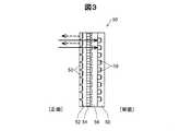
図2及び図3は、センサーモジュール50の構成図である。図2はセンサーモジュール50の一部を示す平面模式図であり、図3はセンサーモジュール50の断面模式図である。図2に示すように、センサーモジュール50は、その受発光領域内において、それぞれ規則的に配列された複数の発光素子53及び複数の受光素子59を有する。ここで、受発光領域とは、複数の発光素子53及び受光素子59を包含する領域をいう。 2 and 3 are configuration diagrams of the
図3に示すように、センサーモジュール50は、多数の発光素子53を平面状に二次元配列した発光層52と、受光層58へ向かう光以外を選択的に遮断する遮光層54と、近赤外線を選択的に透過させる分光層56と、多数の受光素子59を平面状に二次元配列した受光層58とを積層して構成された光学センサーである。そして、このセンサーモジュール50は、正面側(発光層52の側の面)が使用者2の皮膚面に向くように、本体ケース12の裏面側に設けられている。 As shown in FIG. 3, the
発光素子53は、生体へ光を照射する部位であり、例えばLED(Light Emitting Diode)やOLED(Organic light-emitting diode)等により実現される。本実施形態では、血糖値(血液中のグルコース濃度)を測定するため、発光素子53は、皮下透過性を有する近赤外線(波長が0.7μmから2.5μmの光)を含む光を発光可能な素子とする。本実施形態では、発光素子53としてOLEDを用いる。 The
受光素子59は、生体を透過又は反射した光を受光し、受光量に応じた電気信号を出力する部位であり、例えばCCD(Charge Coupled Device Image Sensor)やCMOS(Complementary Metal Oxide Semiconductor Image Sensor)等の撮像素子で実現される。また、1つの受光素子59は、検量に必要な各波長成分を受光する複数の素子を含む。 The
図2に示すように、発光素子53及び受光素子59は、共通のXs−Ys直交座標系で定義されるマトリクス状に配置されている。そして、発光素子53と受光素子59とは、それぞれにおけるXs,Ys軸方向それぞれの配置間隔が同一であるが、Xs−Ys平面において互い違いとなるように配置される。すなわち、発光素子53と受光素子59とのXs,Ys軸方向の位置が、互いに所定長だけずれるように配列されている。 As shown in FIG. 2, the
なお、発光素子53及び受光素子59それぞれの配置間隔は、適宜設定可能である。例えば、配置間隔は、1〜500μmとすると好適であり、製造コストと測定精度との兼ね合いから、例えば50〜200μmとすることもできる。また、発光素子53と受光素子59とが積層された構成に限らず、発光素子53と受光素子59とが並置されていてもよい。 In addition, the arrangement | positioning space | interval of each of the
A2.測定原理:
(A)血糖値の測定
本実施形態における血糖値の測定原理について説明する。測定にあたり、血糖値測定装置10は、センサーモジュール50が使用者2の皮膚面に密着するようにして固定バンド14で固定される。センサーモジュール50を皮膚面に密着させることで、測定光の皮膚面での反射や皮膚面付近での散乱といった測定精度を下げる要因を抑制することができる。そして、センサーモジュール50の直下の生体組織内における血管を測定対象として設定し、測定光がこの血管を透過した透過光を含む光を受光して吸光スペクトルを求め、血糖値を推定演算する。A2. Measuring principle:
(A) Measurement of blood glucose level The measurement principle of blood glucose level in the present embodiment will be described. In the measurement, the blood glucose
(A−1)血管パターンの取得
具体的には、先ず、皮膚面から見た血管パターン(血管位置)を取得する。血管パターンの取得は、公知の静脈認証技術における静脈パターン検出と同様に実現することができる。(A-1) Acquisition of blood vessel pattern Specifically, first, a blood vessel pattern (blood vessel position) viewed from the skin surface is acquired. Acquisition of a blood vessel pattern can be realized in the same manner as vein pattern detection in a known vein authentication technique.
図4は、血管パターン(血管位置)を取得する様子を説明する模式図である。図4に示すように、センサーモジュール50の発光素子53を一斉発光させ、使用者2の皮膚面に測定光を照射する。そして、受光素子59を用いて、測定光が生体組織を透過した光(透過光)や、生体組織で反射した光(反射光)を受光すなわち撮影して、生体画像を取得する。なお、生体画像の取得の際に、センサーモジュール50の一部の発光素子53のみを発光させてもよい。 FIG. 4 is a schematic diagram for explaining how a blood vessel pattern (blood vessel position) is acquired. As shown in FIG. 4, the
血管は非血管部よりも近赤外線を吸収し易いため、取得された生体画像において、血管の部分は非血管の部分よりも放射輝度が低く暗くなる。このため、生体画像において放射輝度が低くなっている部分を抽出することで、血管パターンを抽出することができる。すなわち、生体画像を構成するピクセル毎に、その放射輝度が所定の閾値以下であるか否かによって、該当する受光素子59の直下に血管が存在するか否か、すなわち血管の位置を取得することができる。 Since the blood vessel absorbs near infrared rays more easily than the non-blood vessel part, the blood vessel part has lower radiance and darker than the non-blood vessel part in the acquired biological image. For this reason, a blood vessel pattern can be extracted by extracting the part where the radiance is low in the biological image. That is, for each pixel constituting the living body image, whether or not a blood vessel exists immediately below the corresponding
図5は、生体画像に基づいて得られる血管パターンP4の例を示す図である。血管パターンP4は、生体画像を構成するピクセル毎、すなわち受光素子59の位置毎に、血管であるか非血管領域であるかを示した情報である。図5では、網掛けした帯状の部分が血管4であり、それ以外の白抜きされた部分が非血管領域8として抽出されている。 FIG. 5 is a diagram illustrating an example of a blood vessel pattern P4 obtained based on a biological image. The blood vessel pattern P4 is information indicating whether it is a blood vessel or a non-blood vessel region for each pixel constituting the living body image, that is, for each position of the
(A−2)測定対象の血管部位の選択
血管パターンを取得したならば、続いて、測定対象とする血管(より具体的には血管部位)を選択する。測定対象とする血管部位を、次の選択条件を満たすように選択する。選択条件とは、「血管の分岐部分や合流部分、画像の端部以外の部位であり、且つ、血管長手方向において所定の長さ及び所定の幅を有する」ことである。(A-2) Selection of blood vessel part to be measured Once a blood vessel pattern is acquired, subsequently, a blood vessel (more specifically, a blood vessel part) to be measured is selected. The blood vessel part to be measured is selected so as to satisfy the following selection condition. The selection condition is “a part other than a branching part or a merging part of a blood vessel or an end part of an image and having a predetermined length and a predetermined width in the longitudinal direction of the blood vessel”.
血管の分岐・合流部分5a(図5参照)では、受光光に、測定対象以外の血管を通過した光が混合する可能性がある。測定対象の血管部位以外の血管の透過光は、測定対象の血管部位の吸光スペクトルに影響を及ぼし、測定精度が低下する可能性がある。このため、血管の分岐・合流部分5aを除いた血管部分から測定対象の血管部位を選択することとする。 In the branching / merging
また、生体画像の端部5b(図5参照)では、画像の外側近傍の血管の分岐や合流といった構造が不明であるため、上述と同様の理由による測定精度の低下の可能性がある。これを避けるために、画像端部5bを除いた血管部分から測定対象の血管部位を選択することとする。 In addition, since the structure such as branching and merging of blood vessels near the outside of the image is unknown at the
発光素子53からの照射光は、生体組織内を拡散反射し、その一部が受光素子59にて受光される。つまり、受光素子59にて受光される光の一部が対象血管の透過光となるが、この透過光の割合が高いほど、対象血管の血中成分の特徴をより顕著に表した吸光スペクトルとなり得る。すなわち、測定精度が高くなる。 Irradiation light from the
比較的細く写っている血管(幅方向の長さが短い血管)は、本来的に細い血管であるか、比較的深い位置にある血管である。こういった血管では透過光の光量が少なくなり、測定精度の低下が生じ得る。このため、細く写った血管を除いた血管部分(すなわち、所定の幅を有する血管部位)から、測定対象の血管部位を選択することとする。 A blood vessel that is relatively thin (a blood vessel having a short width in the width direction) is essentially a thin blood vessel or a blood vessel that is relatively deep. In such blood vessels, the amount of transmitted light is reduced, and the measurement accuracy may be reduced. For this reason, the blood vessel part to be measured is selected from the blood vessel part excluding the thinly drawn blood vessel (that is, a blood vessel part having a predetermined width).
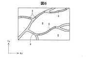
そして、図6は、図5の血管パターンP4に基づいて得られる測定対象の血管部位6の一例である。図6において、血管4のうち、斜線でハッチングされた部分が、測定対象として選択された血管部位6である。 FIG. 6 is an example of the
(A−3)発光部及び受光部の選択
続いて、発光部Lと受光部Sとを選択する。(A-3) Selection of light emitting unit and light receiving unit Subsequently, the light emitting unit L and the light receiving unit S are selected.
図7は、発光部Lと受光部Sとの選択について説明する図である。発光部Lと受光部Sとは、血管の位置に基づいて選択される。本実施形態において、(i)血管の上にある発光部Lを、測定用発光部Ldとして選択し、(ii)測定用発光部Ldから所定距離Wだけ離れており、かつ、血管の上にある受光部Sを、測定用受光部Sdとして選択する。ここで、「血管の上」とは、測定対象の血管部位6の上であることをいう。 FIG. 7 is a diagram illustrating selection between the light emitting unit L and the light receiving unit S. The light emitting part L and the light receiving part S are selected based on the position of the blood vessel. In the present embodiment, (i) the light emitting part L above the blood vessel is selected as the measurement light emitting part Ld, and (ii) is separated from the measurement light emitting part Ld by a predetermined distance W and on the blood vessel. A certain light receiving part S is selected as the measurement light receiving part Sd. Here, “on the blood vessel” means above the
また、(iii)血管の上にない発光部Lをリファレンス用発光部Lrとして選択し、(iv)リファレンス用発光部Lrから所定距離Wだけ離れており、かつ、血管の上にない受光部Sをリファレンス用受光部Srとして選択する。ここで、「血管の上にない」とは、測定対象の血管部位6を含む血管4の上にないことをいう。所定距離Wは、次のように定められる。 In addition, (iii) the light emitting unit L that is not on the blood vessel is selected as the reference light emitting unit Lr, and (iv) the light receiving unit S that is separated from the reference light emitting unit Lr by a predetermined distance W and is not on the blood vessel. Is selected as the reference light receiving portion Sr. Here, “not on the blood vessel” means not on the
図8は、生体組織内での光の伝播を説明する図であり、深さ方向に沿った断面図を示している。ある発光部Lから照射された光は、生体組織内を拡散反射し、照射された光の一部がある受光部Sに到達する。その光の伝播経路は、いわゆるバナナ形状(2つの弧で挟まれた領域)を成し、略中央付近で深さ方向の幅が最も広くなるとともに、発光素子53と受光素子59との間隔に応じて全体の深さ(到達可能な深さ)が深くなる。 FIG. 8 is a diagram for explaining the propagation of light in the living tissue, and shows a cross-sectional view along the depth direction. The light emitted from a certain light emitting unit L is diffusely reflected in the living tissue and reaches the light receiving unit S where a part of the irradiated light is present. The light propagation path has a so-called banana shape (a region sandwiched between two arcs), the width in the depth direction is the largest near the center, and the distance between the light-emitting
測定精度を高めるには、血管4を透過したより多くの透過光が受光部Sで受光されることが望ましい。このことから、発光部Lと受光部Sとの下方に対象血管4が位置することが好ましく、対象血管4の想定する深さDに応じた所定距離Wが定められる。所定距離W、すなわち発光部Lと受光部Sとの間の最適な間隔Wは、血管4の皮膚面からの深さDの約2倍の距離とする。例えば、深さDを3mm程度とすると、最適距離Wは5〜6mm程度となる。次に、発光部Lと発光素子53との関係及び受光部Sと受光素子59との関係について説明する。 In order to increase the measurement accuracy, it is desirable that a larger amount of transmitted light transmitted through the
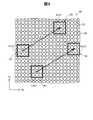
図9は、発光部Lと発光素子53との関係及び受光部Sと受光素子59との関係を示す模式図である。本実施形態における発光部Lは、発光領域R1内の複数の発光素子53から形成されている。発光領域R1は、センサーモジュール50の受発光領域のうちの一部の領域であり、一定の形状及びサイズを有する領域をいう。図9において、発光領域R1は、縦(Ys方向)に3つの発光素子53が入り、横(Xs方向)に3つの発光素子53とが入る領域である。 FIG. 9 is a schematic diagram showing the relationship between the light emitting portion L and the
本実施形態において、センサーモジュール50は、発光領域R1内に含まれる発光素子53の数よりも多い発光素子53を備える。このため、センサーモジュール50の受発光領域には複数の発光部Lが存在することとなる。そして、複数の発光部Lから測定用発光部Ldまたはリファレンス用発光部Lrが選択される。測定用発光部Ldとして発光させる複数の発光素子53が含まれる領域を第1発光領域とも呼び、リファレンス用発光部Lrとして発光させる複数の発光素子53が含まれる領域を第2発光領域とも呼ぶ。 In the present embodiment, the
同様に、本実施形態における受光部Sは、受光領域R2内の複数の受光素子59から形成されている。受光領域R2は、センサーモジュール50の受発光領域のうちの一部の領域であり、一定の形状及びサイズを有する領域をいう。図9において、受光領域R2は、縦(Ys方向)に3つの受光素子59が入り、横(Xs方向)に3つの受光素子59とが入る領域とし、受光領域R2内の全ての受光素子59を受光部Sとして受光させる。 Similarly, the light receiving portion S in the present embodiment is formed from a plurality of light receiving
本実施形態において、センサーモジュール50は、受光領域R2内に含まれる受光素子59の数よりも多い受光素子59を備える。このため、センサーモジュール50の受発光領域には複数の受光部Sが存在することとなる。そして、複数の受光部Sから測定用受光部Sdまたはリファレンス用受光部Srが選択される。測定用受光部Sdとして受光させる複数の受光素子59が含まれる領域を第1受光領域とも呼び、リファレンス用受光部Srとして発光させる複数の受光素子59が含まれる領域を第2受光領域とも呼ぶ。 In the present embodiment, the
なお、受光領域R2内の全ての受光素子59を受光させなくてもよい。本実施形態において、発光部Lと受光部Sとの所定距離Wとは、発光領域R1の重心と受光領域R2の重心との距離をいう。これらの重心は、領域の形状に応じて決まる幾何学的な重心である。 Note that all the
本実施形態において、測定用発光部Ldと測定用受光部Sdとを結ぶ直線L1と、リファレンス用発光部Lrとリファレンス用受光部Srとを結ぶ直線L2とは、略平行である。なお、「略平行」とは、2つの直線L1,L2が成す角が10°以内であることをいう。また、測定用発光部Ldとリファレンス用発光部Lrとの距離Jは、6mm以下であることが好ましく、本実施形態において、この距離Jは5mmである。 In the present embodiment, a straight line L1 connecting the measurement light emitting unit Ld and the measurement light receiving unit Sd and a straight line L2 connecting the reference light emitting unit Lr and the reference light receiving unit Sr are substantially parallel. Note that “substantially parallel” means that the angle formed by the two straight lines L1 and L2 is within 10 °. Further, the distance J between the measurement light emitting part Ld and the reference light emitting part Lr is preferably 6 mm or less, and in the present embodiment, this distance J is 5 mm.
(A−4)測定
測定対象の血管部位6に対する測定用発光部Ld、測定用受光部Sd、リファレンス用発光部Lr、及びリファレンス用受光部Srを選択すると、血糖値の測定を行う。具体的には、まず、測定用発光部Ldを発光させ、その光の測定用受光部Sdからの受光結果Q1(「第1の受光結果Q1」と呼ぶ)を取得する。次に、リファレンス用発光部Lrを発光させ、その光のリファレンス用受光部Srからの受光結果Q2(「第2の受光結果Q2」と呼ぶ)を取得する。そして、受光結果Q1と受光結果Q2とを用いて、吸光スペクトルを生成する。(A-4) Measurement When the measurement light-emitting part Ld, the measurement light-receiving part Sd, the reference light-emitting part Lr, and the reference light-receiving part Sr for the
このとき、例えば発光部Lによる発光光の波長を変化させることで皮膚面への照射光の波長λを近赤外領域内で変化させて、波長λ毎の血管部位6の透過率を求める。透過率T(λ)は、測定用受光部Sdによって得られた光強度Os(λ)と、リファレンス用受光部Srによって得られた光強度Or(λ)とから、T(λ)=Os(λ)/Or(λ)、として得られる。そして、この透過率から吸光率を求めて吸光スペクトルを生成する。 At this time, for example, by changing the wavelength of the light emitted by the light emitting portion L, the wavelength λ of the light irradiated onto the skin surface is changed in the near infrared region, and the transmittance of the
ここで、透過率の算出原理について簡単に説明する。一般的に、発光部Lによる照射光の強度をP(λ)、照射光が透過した物体部分の透過率をT(λ)、受光部Sに定められている感度をS(λ)とすると、受光部Sで得られる光強度O(λ)は、O(λ)=P(λ)・T(λ)・S(λ)、で与えられる。 Here, the principle of calculating transmittance will be briefly described. In general, assuming that the intensity of light emitted from the light emitting portion L is P (λ), the transmittance of the object part through which the irradiated light is transmitted is T (λ), and the sensitivity defined for the light receiving portion S is S (λ). The light intensity O (λ) obtained by the light receiving unit S is given by O (λ) = P (λ) · T (λ) · S (λ).
この関係式より、血管4の透過光を含まないリファレンス用受光部Srで得られる光強度Or(λ)は、非血管領域部分の透過率T(λ)を「1」と仮定すると、Or(λ)=P(λ)・S(λ)、となる。 From this relational expression, the light intensity Or (λ) obtained by the reference light receiving unit Sr that does not include the transmitted light of the
また、血管4の透過光を含む測定用受光部Sdで得られる光強度Os(λ)は、Os(λ)=P(λ)・T(λ)・S(λ)、となる。この2つの式から、透過率T(λ)が求められる。また、この透過率T(λ)は、非血管領域8の透過率に対する相対的な値となる。 The light intensity Os (λ) obtained by the measurement light receiving unit Sd including the light transmitted through the
(A−4−1)測定時の光の照射方法
本実施形態において、一回分の受光結果の取得のための測定用発光部Ldやリファレンス用発光部Lrによる光の照射は、発光領域R1内の複数の発光素子53のうち、発光している発光素子と発光していない発光素子とを含む複数の発光パターンを切り替えながら行われる。なお、図9においては、技術の理解を容易にするために、発光領域R1は、縦(Ys方向)に3つの発光素子53が入り、横(Xs方向)に3つの発光素子53とが入る領域としたが、本実施形態において、発光領域R1は、縦横ともに15個ずつの発光素子53が入る領域である。本明細書において、発光領域R1は、いずれかの発光パターンにおいて発光する発光素子53の外周を囲う領域である。発光領域R1の境界は、いずれかの発光パターンにおいて発光する発光素子53と、いずれの発光パターンにおいても発光しない発光素子53との間に位置する。(A-4-1) Light irradiation method at the time of measurement In the present embodiment, the light irradiation by the measurement light emitting part Ld and the reference light emitting part Lr for obtaining a light reception result for one time is performed in the light emitting region R1. Among the plurality of
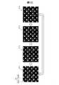
図10は、本実施形態の発光領域R1における複数の発光パターンP11〜P14を示す模式図である。図10において、発光領域R1内の発光素子53のうち、発光している発光素子53を発光素子53onと示し、発光していない発光素子53を発光素子53offと示す。本実施形態において、一回分の受光結果の取得のための測定用発光部Ldによる光の照射時間は4秒である。一回分の受光結果の取得のための測定用発光部Ldによる光の照射は、0.5秒ずつ発光パターンを切り替えながら行われる。具体的には、発光パターンP11から順に、発光パターンP12、P13,P14と発光パターンを切り替え、発光パターンP14の次は、発光パターンP11に切り替える。つまり、本実施形態では、複数の発光パターンがいずれも同じ回数である2回ずつ繰り返される。複数の発光パターンP11〜P14の特徴と利点については、後述する。 FIG. 10 is a schematic diagram showing a plurality of light emission patterns P11 to P14 in the light emitting region R1 of the present embodiment. In FIG. 10, among the
(A−5)血糖値の算出
続いて、吸光スペクトルに基づき、予め定められた血糖値(血液中のグルコース濃度)と吸光度との関係を示す検量線を用いて、血糖値の推定算出を行う。なお、この吸光スペクトルから所定成分(本実施形態ではグルコース)の濃度を算出する技術自体は公知であり、本実施形態ではその公知技術を適用可能である。(A-5) Calculation of blood glucose level Subsequently, based on the absorption spectrum, the blood glucose level is estimated and calculated using a calibration curve showing the relationship between a predetermined blood glucose level (glucose concentration in blood) and absorbance. . In addition, the technique itself which calculates the density | concentration of a predetermined component (in this embodiment glucose) from this light absorption spectrum is well-known, and this well-known technique is applicable in this embodiment.
A3.機能構成:
図11は、本実施形態における血糖値測定装置10の機能構成図である。血糖値測定装置10は、機能的には、操作入力部110と、表示部120と、音出力部130と、通信部140と、照射部210と、撮像部220と、制御部300と、記憶部400とを備えて構成される。A3. Functional configuration:
FIG. 11 is a functional configuration diagram of the blood sugar
操作入力部110は、ボタンスイッチやタッチパネル、各種センサー等の入力装置であり、なされた操作に応じた操作信号を制御部300に出力する。この操作入力部110によって、血糖値の測定開始指示等の各種指示入力が行われる。図1では、操作スイッチ18やタッチパネル16がこれに該当する。 The
表示部120は、LCD(Liquid Crystal Display)等の表示装置であり、制御部300からの表示信号に基づく各種表示を行う。この表示部120に、測定結果等が表示される。図1では、タッチパネル16がこれに該当する。 The
音出力部130は、スピーカー等の音出力装置であり、制御部300からの音信号に基づく各種音出力を行う。この音出力部130によって、血糖値の測定開始や測定終了、低血糖値発生等の報知音が出力される。 The
通信部140は、無線通信機やモデム、有線用の通信ケーブルのジャックや制御回路等の通信装置であり、通信回線と接続して外部との通信を実現する。図1では、通信装置20がこれに該当する。 The
照射部210は、平面状に二次元配列された多数の発光素子53を有する。図2に示すセンサーモジュール50の発光層52がこれに該当する。この照射部210の配置位置(具体的には、Xs−Ys直交座標系における各発光素子53の位置座標)については、発光素子リスト406として記憶されている。 The
撮像部220は、平面状に二次元配列された多数の受光素子59を有する。図2に示すセンサーモジュール50の受光層58がこれに該当する。この撮像部220の配置位置(具体的には、Xs−Yx直交座標系における各受光素子59の位置座標)については、受光素子リスト408として記憶されている。 The
制御部300は、例えばCPUやGPU(Graphics Processing Unit)等のマイクロプロセッサーや、ASIC(特定用途向け集積回路:Application Specific Integrated Circuit)、ICメモリー等の電子部品によって実現され、所定のプログラムやデータ、操作入力部110からの操作信号に基づいて各種の演算処理を実行して、血糖値測定装置10の動作を制御する。図1では、制御基板30がこれに該当する。また、制御部300は、血糖値測定部310と、照射制御部342と、撮像制御部344とを有する。照射制御部342は、複数の発光素子53それぞれを選択的に発光制御する。撮像制御部344は、複数の受光素子59それぞれから受光した光量を取得する。 The
血糖値測定部310は、生体画像取得部314と、血管パターン取得部316と、血管部位選択部318と、測定用受発光部選択部320と、リファレンス用受発光部選択部322と、吸光スペクトル算出部324と、成分値算出部326とを有し、使用者2の血液中のグルコース濃度すなわち血糖値の測定を行う。 The blood glucose
生体画像取得部314は、使用者2の生体画像の取得を行う。生体画像の取得は、公知の静脈認証技術等における生体画像の撮影技術を適宜利用することで実現する。すなわち、発光素子53を一斉発光させ、受光素子59による測光(撮影)を行う。そして、測光結果による放射輝度画像、すなわち生体画像を生成する。生体画像取得部314によって取得された生体画像は、生体画像データ414として記憶される。 The biological
血管パターン取得部316は、生体画像取得部314によって取得された生体画像に対する所定の画像処理を行って、血管パターンを取得する。具体的には、公知の静脈認証技術における生体画像から静脈パターンを識別する技術を適宜利用することで実現する。例えば、生体画像のピクセル毎に、基準放射輝度と比較して2値化やフィルター処理を施す。基準放射輝度未満のピクセルが血管、基準放射輝度以上のピクセルが非血管領域を示すことになる。血管パターン取得部316によって取得された血管パターンは、血管パターンデータ416として記憶される。 The blood vessel
血管部位選択部318は、血管パターン取得部316によって取得された血管パターンに基づいて、所定の選択条件を示す血管部位6を測定対象として選択する。ここで、測定対象とする血管部位6は、1つであっても良いし複数としても良い。測定対象として選択された血管部位6それぞれについては、血管部位データ418として記憶される。 Based on the blood vessel pattern acquired by the blood vessel
図12は、血管部位データ418のデータ構成の一例を示す図である。血管部位データ418は、当該血管部位の識別情報である血管部位ID418aと、部位ピクセルリスト418bと、中心線位置情報418cと、血管長手方向の長さである部位長418dと、測定用発光部データ418eと、測定用受光部データ418fと、リファレンス用発光部データ418gと、リファレンス用受光部データ418hとを格納している。部位ピクセルリスト418bは、当該血管部位に対応するピクセル(すなわち、受光素子59)の一覧である。中心線位置情報418cは、Xs−Ys直交座標系における当該血管部位の中心線(血管幅方向の中心であり血管長さ方向に沿った線)の位置座標の情報である。 FIG. 12 is a diagram illustrating an example of a data configuration of the blood
測定用受発光部選択部320は、測定対象の血管部位6それぞれについて、測定用発光部Ld及び測定用受光部Sdを選択する。具体的には、Xs−Ys直交座標系において(すなわち、皮膚面において)、血管部位6の中心線上の一の位置を測定用発光部Ldとして選択し、測定用発光部Ldから所定距離Wだけ離れており、かつ、血管部位6の中心線上にある測定用受光部Sdを選択する。この測定用発光部Ldと測定用受光部Sdとの選択条件を第1の条件とも呼ぶ。所定距離Wは、最適距離データ410として記憶されている。血管部位6の中心線上の一の位置の選択方法は、例えば、血管部位6の長手方向の略中心位置として定める。選択された測定用発光部Ldは、測定用発光部データ418eとして記憶され、選択された測定用受光部Sdは、測定用受光部データ418fとして記憶される。 The measurement light emitting / receiving
なお、上記第1の条件を満たす測定用発光部Ld及び測定用受光部Sdが存在しない場合には、当該一の位置から血管部位6の中心線に沿って所定の単位距離離れた位置について、同様に上記第1の条件を満たす測定用発光部Ld及び測定用受光部Sdが存在するかを判断する。それでも上記第1の条件を満たす測定用発光部Ld及び測定用受光部Sdが存在しない場合には、同様にこれを繰り返すことで、測定用発光部Ld及び測定用受光部Sdを検索及び選択を行なう。リファレンス用発光部Lrは、リファレンス用発光部データ418gとして記憶され、選択されたリファレンス用発光部Lrは、リファレンス用受光部データ418hとして記憶される。 When there is no measurement light-emitting part Ld and measurement light-receiving part Sd that satisfy the first condition, a position that is a predetermined unit distance away from the one position along the center line of the
リファレンス用受発光部選択部322は、測定用受発光部選択部320によって設定された測定用発光部Ld及び測定用受光部Sdを基準として、血管4の上にない一の位置をリファレンス用発光部Lrとして選択し、リファレンス用発光部Lrから所定距離Wだけ離れており、かつ、血管4の上にないリファレンス用受光部Srを選択する。このリファレンス用発光部Lrとリファレンス用受光部Srとの選択条件を第2の条件とも呼ぶ。 The reference light emitting / receiving
本実施形態において、図7に示すように、測定用発光部Ldとリファレンス用発光部Lrとの距離が5mmであり、測定用発光部Ldと測定用受光部Sdとを結ぶ直線と、リファレンス用発光部Lrとリファレンス用受光部Srとを結ぶ直線とが平行となるリファレンス用受光部Srを選択する。第1の条件と第2の条件と異なる上記選択条件を第3の選択条件と呼ぶ。なお、上記第2の条件及び第3の条件を満たすリファレンス用発光部Lr及びリファレンス用受光部Srが存在しない場合には、再度、測定用受発光部選択部320による測定用発光部Ld及び測定用受光部Sdの検索及び選択を行う。 In the present embodiment, as shown in FIG. 7, the distance between the measurement light emitting portion Ld and the reference light emitting portion Lr is 5 mm, and a straight line connecting the measurement light emitting portion Ld and the measurement light receiving portion Sd is used for the reference. The reference light receiving part Sr is selected in which the straight line connecting the light emitting part Lr and the reference light receiving part Sr is parallel. The selection condition that is different from the first condition and the second condition is referred to as a third selection condition. When the reference light emitting unit Lr and the reference light receiving unit Sr satisfying the second condition and the third condition do not exist, the measurement light emitting unit Ld and the measurement by the measurement light receiving / emitting
吸光スペクトル算出部324は、測定対象の血管部位6それぞれについて、吸光スペク
トルを生成する。具体的には、測定用受光部Sdからの第1の受光結果Q1及びリファレンス用受光部Srからの第2の受光結果Q2をもとに、波長λ毎の透過率Tを算出することで、吸光スペクトルを生成する。更に、測定対象の血管部位6が複数有る場合は、これら複数の測定対象の血管部位6それぞれの吸光スペクトルを平均して平均吸光スペクトルを算出する。吸光スペクトル算出部324によって算出された吸光スペクトルは、吸光スペクトルデータ420として記憶される。The absorption
成分値算出部326は、吸光スペクトル算出部324によって算出された吸光スペクトルに基づいて、目的とする血液成分の血中濃度であるグルコース濃度(すなわち、血糖値)を算出する。本実施形態では、吸光スペクトルを、重回帰分析法、主成分回帰分析法、PLS回帰分析法、独立成分分析法等の分析法を用いる。なお、測定対象の血管部位6が複数有る場合には、各血管部位6に係る吸光スペクトルを平均した平均吸光スペクトルから血糖値を算出する。成分値算出部326によって算出された血糖値は、測定時刻と対応付けて、測定血糖値データ422として蓄積記憶される。 The component
記憶部400は、ROMやRAM、ハードディスク等の記憶装置であり、制御部300が血糖値測定装置10を統合的に制御するためのプログラムやデータ等を記憶しているとともに、制御部300の作業領域として用いられ、制御部300が実行した演算結果や、操作入力部110からの操作データ等が一時的に格納される。図1では、制御基板30に搭載されるメインメモリーや測定データ用メモリーがこれに該当する。また、記憶部400には、システムプログラム402と、血糖値測定プログラム404と、発光素子リスト406と、受光素子リスト408と、最適距離データ410と、生体画像データ414と、血管パターンデータ416と、血管部位データ418と、吸光スペクトルデータ420と、測定血糖値データ422とが記憶される。 The
A4.生体情報取得方法:
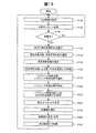
図13は、生体情報取得方法としての血糖値測定処理の流れを説明するフローチャートである。この処理は、制御部300が、血糖値測定プログラム404に従った処理を実行することで実現される。A4. Biometric information acquisition method:
FIG. 13 is a flowchart for explaining the flow of blood sugar level measurement processing as a biological information acquisition method. This process is realized by the
図13によれば、血糖値測定部310が、使用者の血糖値を測定する測定処理を行う。まず、血糖値測定部310の生体画像取得部314が、センサーモジュール50の発光面のほぼ全面(すなわち、ほぼ全ての発光素子53を含む範囲)を発光範囲とし、発光範囲内の発光素子53を発光させて、使用者の生体画像を取得する(ステップP120)。続いて、血管パターン取得部316が、得られた生体画像に基づいて、皮膚面から見た血管パターンを取得する(ステップP130)。その結果、血管パターンが得られないならば(ステップP140:NO)、ステップP120に戻る。 According to FIG. 13, the blood sugar
血管パターンが得られたならば(ステップP140:YES)、血管部位選択部318が、得られた血管パターンに基づいて、所定の選択条件を満たす測定対象の血管部位6を選択する(ステップP150)。そして、測定用受発光部選択部320が、測定用発光部Ld及び測定用受光部Sdを選択する(ステップP160)。次いで、測定用発光部Ldを発光させ(ステップP170)、選択された測定用受光部Sdにより第1の受光結果Q1を得る(ステップP180)。 If a blood vessel pattern is obtained (step P140: YES), the blood vessel
その後、リファレンス用受発光部選択部322が、リファレンス用発光部Lr及びリファレンス用受光部Srを選択する(ステップP190)。次いで、リファレンス用発光部Lrを発光させ(ステップP200)、選択されたリファレンス用受光部Srにより第2の受光結果Q2を得る(ステップP210)。なお、第1の受光結果を取得する工程(ステップP180)と、第2の受光結果を取得する工程(ステップP210)との間には、所定時間の間隔を設ける。本実施形態では、所定時間の間隔として、5秒間の間隔を設ける。 Thereafter, the reference light emitting / receiving
次いで、吸光スペクトル算出部324が、第1の受光結果Q1及び第2の受光結果Q2を用いて、当該血管部位6についての吸光スペクトルを生成する(ステップP220)。更に、測定対象の血管部位6が複数有る場合には、血管部位6毎の吸光スペクトルを平均した吸光スペクトルを算出する。 Next, the absorption
その後、成分値算出部326が、吸光スペクトルに基づいて、血液中のグルコース濃度すなわち血糖値を算出する(ステップP230)。そして、算出した血糖値を表示部120に表示させるとともに、測定時刻と対応付けて蓄積記憶する(ステップP240)。所定の待機時間の経過を待機した後(ステップP250)、ステップP120に戻り、同様に次回の血糖値の測定を行う。 Thereafter, the component
A5.作用効果:
A5−1.発光パターンを用いた作用効果
本実施形態の生体情報取得装置10において、測定用発光部Ldまたはリファレンス用発光部Lrによる光の照射は、複数の発光パターンP11〜P14(図10参照)を切り替えながら行われる。このため、本実施形態の生体情報取得装置10によれば、ある発光パターンにおいて発光している発光素子53が、他の発光パターンにおいて発光していない場合があり、発光素子53の連続発光を抑制し、発光素子53の発熱に起因する劣化を抑制できる。A5. Effect:
A5-1. Effects Using Light Emitting Patterns In the biological
一回分の受光結果の取得のための測定用発光部Ldによる光の照射を、複数の発光パターンを切り替えながら行うことによって、発光素子53の劣化を抑制することを示す結果を、以下に示す。具体的には、本実施形態の発光パターンやその他の発光パターンを用いた場合の光源寿命を、比較例と比較した結果を示す。 A result showing that the deterioration of the
図14は、本実施形態とは異なる発光パターンP21〜P23を示す模式図である。この形態における光の照射は、約0.67秒ずつ発光パターンを切り替えながら行われる。具体的には、発光パターンP21から順に、発光パターンP22、P23と発光パターンを切り替え、発光パターンP23の次は、発光パターンP21に切り替える。なお、上記の本実施形態に用いた複数の発光パターンP11〜P14(図10参照)を総称して点灯パターンAと呼び、図14に示した複数の発光パターンP21〜P23を総称して点灯パターンBと呼ぶ。 FIG. 14 is a schematic diagram showing light emission patterns P21 to P23 different from the present embodiment. The light irradiation in this form is performed while switching the light emission pattern by about 0.67 seconds. Specifically, the light emission patterns P22 and P23 and the light emission pattern are switched sequentially from the light emission pattern P21, and the light emission pattern P23 is switched to the light emission pattern P21. Note that the plurality of light emission patterns P11 to P14 (see FIG. 10) used in the above-described embodiment are collectively referred to as a lighting pattern A, and the plurality of light emission patterns P21 to P23 illustrated in FIG. Call it B.
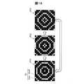
図15は、本実施形態とは異なる発光パターンP31〜P33を示す模式図である。この形態における光の照射は、約0.67秒ずつ発光パターンを切り替えながら行われる。具体的には、発光パターンP31から順に、発光パターンP32、P33と発光パターンを切り替え、発光パターンP33の次は、発光パターンP31に切り替える。なお、図15に示した複数の発光パターンP31〜P33を総称して点灯パターンCと呼ぶ。 FIG. 15 is a schematic diagram showing light emission patterns P31 to P33 different from the present embodiment. The light irradiation in this form is performed while switching the light emission pattern by about 0.67 seconds. Specifically, the light emission patterns P32 and P33 and the light emission pattern are switched sequentially from the light emission pattern P31, and the light emission pattern P33 is switched to the light emission pattern P31. A plurality of light emission patterns P31 to P33 shown in FIG.
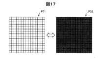
図16及び図17は、比較例の点灯パターンを示す模式図である。図16は、発光領域R1内の発光素子53を全て連続点灯させているパターンP41を示す模式図である。また、図17は、発光領域R1内の全ての発光素子53を点灯させているパターンP51と、発光領域R1内の全ての発光素子53を点灯させないパターンP51とを示す模式図である。図17に示すパターンP51,P52は、2秒ずつ交互に切り替わる。なお、図16に示したパターンP41を点灯パターンDと呼び、図17に示したパターンP51,P52を総称して点灯パターンEとも呼ぶ。 16 and 17 are schematic diagrams illustrating lighting patterns of comparative examples. FIG. 16 is a schematic diagram showing a pattern P41 in which all the
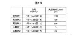
図18は、各点灯パターンにおいて発光素子を点灯させた場合の光源寿命を測定した結果である。光源寿命の結果は、発光素子の光量が、実験開始時の光量に対して80%の光量となるまでの時間を示す。また、発光素子として、OLEDを用いた。OLEDの作成方法としては、特開2012−219078号公報を参考にすることができる。 FIG. 18 shows the result of measuring the lifetime of the light source when the light emitting element is turned on in each lighting pattern. The result of the light source lifetime indicates the time until the light amount of the light emitting element becomes 80% of the light amount at the start of the experiment. Moreover, OLED was used as a light emitting element. As a method for producing an OLED, Japanese Patent Application Laid-Open No. 2012-219078 can be referred to.
発光している発光素子53と発光していない発光素子53とを含む複数の発光パターンを切り替えながら光の照射を行う実施例1から実施例3は、そうではない比較例1および比較例2と比較して、光源寿命が長いことが図18から分かる。つまり、この結果から、一回分の受光結果の取得のための光の照射を複数の発光パターンを切り替えながら行うことにより、発光素子53の劣化を抑制できることが分かる。 Examples 1 to 3 in which light irradiation is performed while switching a plurality of light emission patterns including a
点灯パターンA,B,C(図10,14,15参照)では、切り替わる前の発光パターンにおいて発光した発光素子は、切り替わった後の発光パターンにおいて発光しない。このようにすることにより、発光素子53の劣化を抑制できる。 In the lighting patterns A, B, and C (see FIGS. 10, 14, and 15), the light emitting elements that emit light in the light emission pattern before switching do not emit light in the light emission pattern after switching. By doing in this way, deterioration of the
また、点灯パターンA,B,C(図10,14,15参照)では、全ての発光パターンにおいて、発光している発光素子53onと隣接する発光素子53の中で、発光していない発光素子53offが存在する。このようにすることにより、発光している発光素子53onが発する熱が周囲に存在する発光していない発光素子53offへ拡散することにより放熱することができるため、発光素子53の劣化を抑制できる。 In the lighting patterns A, B, and C (see FIGS. 10, 14, and 15), the light emitting element 53off that does not emit light among the light emitting elements 53on adjacent to the light emitting element 53on that emits light in all the light emitting patterns. Exists. By doing so, heat generated by the light emitting element 53on that emits light can be dissipated by diffusing to the light emitting element 53off that does not emit light in the surrounding area, so that deterioration of the
また、点灯パターンA(図10参照)である全ての発光パターンにおいて、発光している発光素子53onと隣接する発光素子53は、いずれも発光していない発光素子53offである。このようにすることにより、さらに効率的に発光している発光素子53onが発する熱を放熱することができるため、発光素子53の劣化を抑制できる。 Moreover, in all the light emission patterns which are the lighting pattern A (refer FIG. 10), the
また、点灯パターンA,B,C(図10,14,15参照)では、いずれかの発光パターンで発光した発光素子53は、他の発光パターンにおいて発光しない。このため、発光した発光素子53onが発した熱が、発光していない時間において放熱することができるため、局所的な蓄熱を抑制できる。 In the lighting patterns A, B, and C (see FIGS. 10, 14, and 15), the
また、点灯パターンB,C(図14,15参照)では、発光部Lの中心に対して点対称となる位置の発光素子が発光しており、また、発光部Lの中心を通る線に対して線対称となる位置の発光素子が発光している。このため、発光パターン間における光量のばらつきを抑制でき、この結果として、生体情報を精度良く取得できる。 Further, in the lighting patterns B and C (see FIGS. 14 and 15), the light emitting element at a position that is point-symmetric with respect to the center of the light emitting portion L emits light, and the line passing through the center of the light emitting portion L is emitted. The light emitting elements at positions that are line symmetric are emitting light. For this reason, variation in the amount of light between the light emission patterns can be suppressed, and as a result, biological information can be obtained with high accuracy.
また、点灯パターンA,B,C(図10,14,15参照)では、いずれも所定数以上の発光素子53が発光している。具体的には、点灯パターンA,B,C(図10,14,15参照)では、いずれも発光領域R1内に含まれる発光素子の合計に対して10%以上の発光素子53が発光している。このため、所定数より少ない発光素子53を発光させる場合と比較して、本実施形態の生体情報取得装置10は、十分な発光強度を得ることができる。この結果として、本実施形態の生体情報取得装置10によれば、生体情報を精度よく取得できる。なお、所定数は、より好ましくは、発光領域R1内に含まれる発光素子の合計に対して20%であり、さらに好ましくは、発光領域R1内に含まれる発光素子の合計に対して30%である。 Also, in the lighting patterns A, B, and C (see FIGS. 10, 14, and 15), a predetermined number or more of the
なお、発光素子53の発熱を抑制することにより、生体情報取得装置10を装着した生体への熱の伝導も抑制できる。このため、発光素子53の発熱に起因する生体の低温やけどの虞についても抑制できる。また、発光素子53の発熱を抑制することにより、生体情報取得装置10自体の温度上昇を抑制できるため、温度ドリフトによる生体情報取得装置10の精度低下についても抑制できる。さらに、生体は、光の散乱体であるため、受光量が小さい。このため、発光パワーを高くする必要がある。特に、血液中のグルコース等の濃度測定時は、血管位置の取得時よりも発光パワーを高くすることが好ましい。 In addition, by suppressing the heat generation of the
A5−2.その他の作用効果
本実施形態の生体情報取得装置10において、血管の位置に基づいて測定用発光部Ldを選択することにより、血管に関連した生体情報を取得するのに適した発光部Lを測定用発光部Ldとして選択できる。このため、本実施形態の生体情報取得装置10によれば、血管に関連した生体情報を精度良く取得することができる。A5-2. Other Operational Effects In the biological
また、本実施形態の生体情報取得装置10では、発光素子53としてOLEDを用いている。OLEDに使用される有機材料のガラス転移温度は、一般的に90℃から130℃程度であるが、発光により生じる熱により、ガラス転移温度まで達する虞がある。そして、ガラス転移温度に達した場合、OLEDの発光効率の低下などが起こり得る。しかし、本実施形態では、発光素子において発生した熱を放熱することにより、発光素子53の劣化を抑制することができるため、OLEDを用いることができる。 In the biological
本実施形態の生体情報取得装置10において、第1の受光結果における光源(測定用発光部Ld)と第2の受光結果における光源が異なる。このため、測定用発光部Ldは、血管の上にあるものを選択でき、リファレンス用発光部Lrは血管の上にないものを選択できる。この結果として、血管の上にある測定用発光部Ldから発光された光を血管の上にある測定用受光部Sdが受光することにより得られる第1の受光結果は、照射された光が血管を通る割合が多いため、血管や血管内血液に関する情報を多く含む。一方、血管の上にないリファレンス用発光部Lrから発光された光を血管の上にないリファレンス用受光部Srが受光することにより得られる第2の受光結果は、照射された光が血管を通る割合が少ないため、血管や血管内の血液に関する情報が少なくなる。このような第1の受光結果と第2の受光結果とを用いて生体情報を取得するため、本実施形態の生体情報取得装置10によれば、生体情報を精度よく取得できる。 In the biological
また、本実施形態の生体情報取得装置10において、測定用発光部Ldと測定用受光部Sdとを結ぶ直線と、リファレンス用発光部Lrとリファレンス用受光部Srとを結ぶ直線とは、略平行である。また、測定用発光部Ldとリファレンス用発光部Lrとの距離は、6mm以下である。このため、測定用発光部Ldにより発せられた光が測定用受光部Sdへ進む光路における生体の構造は、リファレンス用発光部Lrにより発せられた光がリファレンス用受光部Srへ進む光路における生体の構造と比較して、血管部位6を通らないという点以外において近似する。よって、本実施形態の生体情報取得装置10によれば、第1の受光結果と第2の受光結果とを用いて生体情報を取得するため、生体情報を精度よく取得できる。 In the biological
また、本実施形態の生体情報取得装置10において、受発光領域の一部の領域として、一定の形状及びサイズを有する発光領域R1を選択するとともに、選択された発光領域R1内の複数の発光素子53を、測定用発光部Ld又はリファレンス用発光部Lrとして発光させる。このように、本実施形態における発光部Lは、複数の発光素子53から形成されている。このため、一つの発光部が一つの発光素子で形成されている場合と比較して、本実施形態の生体情報取得装置10は、十分な発光強度を得ることができる。この結果として、本実施形態の生体情報取得装置10によれば、生体情報を精度よく取得できる。 In the biological
同様に、本実施形態の生体情報取得装置10において、受発光領域の一部の領域として、一定の形状及びサイズを有する受光領域R2を選択するとともに、選択された受光領域R2内の複数の受光素子59を、測定用受光部Sd又はリファレンス用受光部Srとして受光させる。このように、本実施形態における受光部Sは、複数の受光素子59から形成されている。このため、一つの受光部が一つの受光素子で形成されている場合と比較して、本実施形態の生体情報取得装置10は、十分な受光量を得ることができる。この結果として、本実施形態の生体情報取得装置10によれば、生体情報を精度よく取得できる。 Similarly, in the biological
また、本実施形態の生体情報取得装置10において、一つの発光部Lが、より小さな複数の発光素子53の集合により形成されるので、発光部Lの位置を小さな発光素子53のピッチの単位で選択することができる。このため、本実施形態の生体情報取得装置10によれば、発光部Lを選択する自由度が向上する。 Further, in the biological
同様に、本実施形態の生体情報取得装置10において、一つの受光部Sが、より小さな複数の受光素子59の集合により形成されるので、受光部Sの位置を小さな受光素子59のピッチの単位で選択することができる。このため、本実施形態の生体情報取得装置10によれば、受光部Sを選択する自由度が向上する。 Similarly, in the biological
本実施形態の生体情報取得方法において、第1の受光結果を取得する工程(ステップP180(図13参照))と、第2の受光結果を取得する工程(ステップP210)との間には、所定の時間が設けられている。このため、測定用発光部Ldが発光した光をリファレンス用受光部Srが受光することや、リファレンス用発光部Lrが発光した光を測定用受光部Sdが受光することを抑制することができる。この結果として、本実施形態の生体情報取得方法によれば、生体情報を精度よく取得できる。 In the biological information acquisition method of the present embodiment, a predetermined interval between the step of acquiring the first light reception result (step P180 (see FIG. 13)) and the step of acquiring the second light reception result (step P210). Time is provided. For this reason, it is possible to suppress the reference light receiving unit Sr from receiving the light emitted from the measurement light emitting unit Ld and the light receiving unit Sd from receiving the light emitted from the reference light emitting unit Lr. As a result, according to the biological information acquisition method of this embodiment, biological information can be acquired with high accuracy.
B.第2実施形態:
第2実施形態は、第1実施形態と比較して、リファレンス用発光部Lrとリファレンス用受光部Srとの選択方法が異なるが、それ以外は同じである。B. Second embodiment:
The second embodiment differs from the first embodiment in the selection method of the reference light emitting portion Lr and the reference light receiving portion Sr, but is otherwise the same.
第2実施形態の生体情報取得装置10Aでは、生体画像を取得した際の放射輝度の高さが、受発光領域内全体において上位10%以内である位置を、リファレンス用発光部Lr及びリファレンス用受光部Srとして選択する。なお、リファレンス用発光部Lrとリファレンス用受光部Srとの距離は、第1実施形態と同じ所定距離Wとする。 In the biological information acquisition apparatus 10A of the second embodiment, the reference light emitting unit Lr and the reference light receiving are located at positions where the radiance height when the biological image is acquired is within the top 10% in the entire light receiving and emitting region. Select as part Sr. Note that the distance between the reference light emitting portion Lr and the reference light receiving portion Sr is the same predetermined distance W as in the first embodiment.
前述の通り、血管は非血管部よりも近赤外線を吸収し易いため、取得された生体画像において、血管の部分は非血管の部分よりも放射輝度が低くなる。また、人体には、いたるところに毛細血管が通っている。このため、生体画像を取得した際に放射輝度の高さがいずれも上位10%以内である位置は、毛細血管を含む血管が存在しない可能性が高い。このような位置がリファレンス用発光部Lr及びリファレンス用受光部Srとして選択されることにより、リファレンス用発光部Lrから照射された光からリファレンス用受光部Srで得られた第2の受光結果は、血管や血管内の血液に関する情報が少なくなる。この結果として、本実施形態の生体情報取得装置10によれば、生体情報を精度よく取得できる。 As described above, since the blood vessel absorbs near infrared rays more easily than the non-blood vessel portion, the radiance of the blood vessel portion is lower than that of the non-blood vessel portion in the acquired biological image. In addition, capillaries pass through the human body everywhere. For this reason, there is a high possibility that blood vessels including capillaries do not exist at positions where the radiance is within the top 10% when a biological image is acquired. By selecting such a position as the reference light emitting unit Lr and the reference light receiving unit Sr, the second light reception result obtained by the reference light receiving unit Sr from the light emitted from the reference light emitting unit Lr is: Information about blood vessels and blood in blood vessels is reduced. As a result, according to the biological
C.変形例:
この発明は前記実施例やその変形例に限られるものではなく、その要旨を逸脱しない範囲において種々の態様において実施することが可能であり、例えば次のような変形も可能である。C. Variations:
The present invention is not limited to the above-described embodiments and modifications thereof, and can be carried out in various modes without departing from the gist thereof. For example, the following modifications are possible.
C1.変形例1:
前記実施形態では、図10に示す複数の発光パターンP11〜P14を用いたが、本発明はこれに限定されない。例えば、以下のような発光パターンを用いても良い。C1. Modification 1:
In the said embodiment, although the several light emission pattern P11-P14 shown in FIG. 10 was used, this invention is not limited to this. For example, the following light emission pattern may be used.
図19は、本実施形態とは異なる発光パターンP61〜P64を示す模式図である。本形態において、一回分の受光結果の取得のための測定用発光部Ldによる光の照射時間は4秒である。一回分の受光結果の取得のための測定用発光部Ldによる光の照射は、0.5秒ずつ発光パターンを切り替えながら行われる。具体的には、P61から順に、発光パターンP62、P63、P64と発光パターンを切り替え、発光パターンP64の次は、発光パターンP61に切り替える。つまり、本実態では、複数の発光パターンがいずれも同じ回数である2回ずつ繰り返される。 FIG. 19 is a schematic diagram showing light emission patterns P61 to P64 different from the present embodiment. In the present embodiment, the irradiation time of light by the measurement light emitting unit Ld for obtaining one light reception result is 4 seconds. Irradiation of light by the measurement light emitting unit Ld for obtaining a light reception result for one time is performed while switching the light emission pattern every 0.5 seconds. Specifically, the light emission patterns P62, P63, and P64 are switched in order from P61, and the light emission pattern P64 is switched to the light emission pattern P61. That is, in this actual situation, a plurality of light emission patterns are repeated twice, which is the same number of times.
図20は、本実施形態とは異なる発光パターンP71〜P73を示す模式図である。本形態において、一回分の受光結果の取得のための測定用発光部Ldによる光の照射時間は4秒である。一回分の受光結果の取得のための測定用発光部Ldによる光の照射は、約0.67秒ずつ発光パターンを切り替えながら行われる。具体的には、P71から順に、発光パターンP72、P73と発光パターンを切り替え、発光パターンP73の次は、発光パターンP71に切り替える。つまり、本実態では、複数の発光パターンがいずれも同じ回数である2回ずつ繰り返される。 FIG. 20 is a schematic diagram showing light emission patterns P71 to P73 different from the present embodiment. In the present embodiment, the irradiation time of light by the measurement light emitting unit Ld for obtaining one light reception result is 4 seconds. Irradiation of light by the measurement light emitting unit Ld for acquiring a light reception result for one time is performed while switching the light emission pattern by about 0.67 seconds. Specifically, the light emission patterns P72 and P73 and the light emission pattern are switched sequentially from P71, and the light emission pattern P73 is switched to the light emission pattern P71. That is, in this actual situation, a plurality of light emission patterns are repeated twice, which is the same number of times.
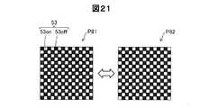
図21は、本実施形態とは異なる発光パターンP81〜P82を示す模式図である。本形態において、一回分の受光結果の取得のための測定用発光部Ldによる光の照射時間は4秒である。一回分の受光結果の取得のための測定用発光部Ldによる光の照射は、1秒ずつ発光パターンを切り替えながら行われる。具体的には、発光パターンP81と、発光パターンP82とをこの順に交互に切り替える。つまり、本実態では、複数の発光パターンがいずれも同じ回数である2回ずつ繰り返される。 FIG. 21 is a schematic diagram showing light emission patterns P81 to P82 different from the present embodiment. In the present embodiment, the irradiation time of light by the measurement light emitting unit Ld for obtaining one light reception result is 4 seconds. Light irradiation by the measurement light emitting unit Ld for obtaining a light reception result for one time is performed while switching the light emission pattern for one second. Specifically, the light emission pattern P81 and the light emission pattern P82 are alternately switched in this order. That is, in this actual situation, a plurality of light emission patterns are repeated twice, which is the same number of times.
図20,21に記載の発光パターンでは、切り替わる前の発光パターンにおいて発光した発光素子は、切り替わった後の発光パターンにおいて発光しない。また、図19,20,21に記載の発光パターンでは、全ての発光パターンにおいて、発光している発光素子53onと隣接する発光素子53の中で、発光していない発光素子53offが存在する。 In the light emission patterns described in FIGS. 20 and 21, the light emitting elements that emit light in the light emission pattern before switching do not emit light in the light emission pattern after switching. In the light emission patterns described in FIGS. 19, 20, and 21, in all the light emission patterns, there is a light emitting element 53off that does not emit light among the
また、図20,21に記載の発光パターンでは、いずれかの発光パターンで発光した発光素子53は、他の発光パターンにおいて発光しない。また、図19,20,21に記載の発光パターンでは、発光部Lの中心に対して点対称となる位置の発光素子が発光しており、また、発光部Lの中心を通る線に対して線対称となる位置の発光素子が発光している。 20 and 21, the
なお、一回分の受光結果を得るために使用される1組の複数の発光パターンは、以下のような特徴点のうちの1つ以上を有することが好ましい。
<特徴点1>1組の複数の発光パターンは、発光する発光素子53の少なくとも一部が互いに異なる。
<特徴点2>各発光パターンにおいて発光する発光素子53が、発光部53内(発光領域R1内)の中心に対して点対称となる位置にある。
<特徴点3>各発光パターンにおいて発光する発光素子53が、発光部53内(発光領域R1内)の中心を通る線に対して線対称となる位置にある。
<特徴点4>1組の複数の発光パターンにおいて、任意の発光パターンにおいて発光した発光素子53は、その次の発光パターンにおいては発光しない。
<特徴点5>各発光パターンにおいて、発光する発光素子53の4近傍位置にある他の4つの発光素子53は発光しない。
<特徴点6>各発光パターンにおいて、発光する発光素子53の8近傍位置にある他の8つの発光素子53は発光しない。
<特徴点7>1組の複数の発光パターンにおいて発光する個々の発光素子53に関して、1組の複数の発光パターンを通算した発光回数N(Nは1以上の整数)は互いに等しい。
<特徴点8>発光部53内のすべての発光素子53に関して、1組の複数の発光パターンを通算した発光回数が少なくとも1回以上である。
<特徴点9>1組の複数の発光パターンにおける各発光パターンの使用回数M(Mは1以上の整数)は、互いに等しい。In addition, it is preferable that 1 set of several light emission patterns used in order to obtain the light reception result for 1 time have one or more of the following feature points.
<Feature 1> At least a part of the
<
<Feature 3> The
<
<
<
<Feature 7> With respect to each light emitting
<
<Feature Point 9> The number M of use of each light emission pattern in a set of light emission patterns (M is an integer of 1 or more) is equal to each other.
図10に示した1組の発光パターンP11〜P14は、上記特徴点1,3,4,5,6,7,8,9を有する。このような1組の発光パターンP11〜P14を使用すれば、同じ発光素子53の連続発光を防止できるので、発光素子53の発熱に起因する劣化を抑制できる。 A set of light emission patterns P11 to P14 shown in FIG. 10 has the
C2.変形例2:
前記実施形態では、生体情報として血糖値を取得する。しかし、本発明はこれに限られない。生体情報として、例えば、使用者である生体の血液中の酸素飽和度を取得してもよい。血液中の酸素飽和度とは、赤血球中のヘモグロビンのうち、酸素と結合しているヘモグロビンの割合のことである。血液中のヘモグロビンは、酸素との結合の有無により赤色光と赤外光の吸光度が異なる。そこで、例えば、赤色光を発光若しくは受光する素子や、赤外光を発光若しくは受光する素子などのような発光波長及び受光波長を異ならせた素子を複数組用いることにより、酸素飽和度を取得することができる。C2. Modification 2:
In the said embodiment, a blood glucose level is acquired as biometric information. However, the present invention is not limited to this. As the biological information, for example, the oxygen saturation in the blood of the user who is the user may be acquired. The oxygen saturation in blood is the proportion of hemoglobin that is bound to oxygen out of hemoglobin in red blood cells. The hemoglobin in blood has different absorbances for red light and infrared light depending on the presence or absence of binding to oxygen. Therefore, for example, oxygen saturation is obtained by using a plurality of sets of elements having different emission wavelengths and light reception wavelengths, such as elements that emit or receive red light and elements that emit or receive infrared light. be able to.
また、前記実施形態では、本発明を血糖値の取得装置に用いたが、本発明はこれに限らない。本発明を適用する機器としては、例えば、肌診断機、体脂肪測定器、体内蛍光物質観察機器、静脈認証機器、赤外スキャナー機器、皮膚癌診断機器、瞳観察装置、血管観察装置を挙げることができ、これらの機器の光源に本発明の発光部を適用することができる。 Moreover, in the said embodiment, although this invention was used for the acquisition apparatus of a blood glucose level, this invention is not restricted to this. Examples of devices to which the present invention is applied include skin diagnostic devices, body fat measuring devices, internal fluorescent substance observation devices, vein authentication devices, infrared scanner devices, skin cancer diagnostic devices, pupil observation devices, and blood vessel observation devices. The light-emitting portion of the present invention can be applied to the light source of these devices.
C3.変形例3:
前記実施形態では、受光結果の取得における光の照射は、複数の発光パターンを切り替えながら行われる。しかし、本発明はこれに限られない。つまり、血管の位置を特定する際の光の照射が複数の発光パターンを切り替えながら行われてもよい。ただし、血管中の情報(グルコース濃度、酸素飽和度等)をより多く取得するには生体を透過した光をより多く受光部にて受光する必要があるため、受光結果の取得における光の照射量の方が、血管の位置を特定する際の光の照射量よりも大きいことが好ましい。このため、受光結果の取得における光の照射が複数の発光パターンを切り替えながら行われることが好ましい。C3. Modification 3:
In the embodiment, the light irradiation in obtaining the light reception result is performed while switching a plurality of light emission patterns. However, the present invention is not limited to this. That is, light irradiation for specifying the position of a blood vessel may be performed while switching a plurality of light emission patterns. However, in order to acquire more information in the blood vessels (glucose concentration, oxygen saturation, etc.), it is necessary to receive more light that has passed through the living body at the light receiving unit, so the light irradiation amount in acquiring the light reception result It is preferable that this is larger than the amount of light irradiated when the position of the blood vessel is specified. For this reason, it is preferable that the light irradiation in obtaining the light reception result is performed while switching a plurality of light emission patterns.
C4.変形例4:
前記実施形態では、第1の受光結果Q1を取得する工程(ステップP180)の後、第2の受光結果Q2を取得する工程(ステップP210)を行なう。しかし、本発明はこれに限られない。第2の受光結果Q2を取得する工程の後、第1の受光結果Q1を取得する工程を行なっても良い。C4. Modification 4:
In the embodiment, after the step of obtaining the first light reception result Q1 (step P180), the step of obtaining the second light reception result Q2 (step P210) is performed. However, the present invention is not limited to this. You may perform the process of acquiring the 1st light reception result Q1 after the process of acquiring the 2nd light reception result Q2.
C5.変形例5:
前記実施形態では、血管4の上にない一の位置をリファレンス用発光部Lrとして選択し、リファレンス用発光部Lrから所定距離Wだけ離れており、かつ、血管4の上にないリファレンス用受光部Srを選択する。しかし、本発明は、これに限られない。つまり、上記条件に加え、リファレンス用発光部Lrとリファレンス用受光部Srとの間に血管の上である位置を含まないとの条件を加えても良い。このようにすることにより、リファレンス用受光部Srにて得られる第2の受光結果は、照射された光が血管を通る割合が少なくなるため、血管や血管内の血液に関する情報がより少なくなる。この結果として、生体情報を精度よく取得できる。C5. Modification 5:
In the above-described embodiment, one position that is not on the
C6.変形例6:
前記実施形態では、発光部L及び受光部Sの選択(例えば、ステップP160)の後、発光部Lの発光を行う(例えば、ステップP170)。しかし、本発明はこれに限られない。発光部Lの発光後に、受光部Sの選択を行っても良い。C6. Modification 6:
In the embodiment, after the light emitting unit L and the light receiving unit S are selected (for example, step P160), the light emitting unit L emits light (for example, step P170). However, the present invention is not limited to this. After the light emitting unit L emits light, the light receiving unit S may be selected.
C7.変形例7:
前記実施形態では、発光部Lの選択後、発光部Lから所定距離W離れた受光部Sを選択している。しかし、本発明はこれに限られない。受光部Sの選択後、受光部Sから所定距離W離れた発光部Lを選択してもよい。また、発光部Lと受光部Sの位置は、図7に示した例以外の種々の位置をとり得る。C7. Modification 7:
In the embodiment, after the light emitting unit L is selected, the light receiving unit S that is a predetermined distance W away from the light emitting unit L is selected. However, the present invention is not limited to this. After the selection of the light receiving part S, the light emitting part L separated from the light receiving part S by a predetermined distance W may be selected. Further, the positions of the light emitting part L and the light receiving part S can take various positions other than the example shown in FIG.
なお、前述した各実施例および各変形例における構成要素の中の、独立請求項で記載された要素以外の要素は、付加的な要素であり、適宜省略可能である。 It should be noted that elements other than those described in the independent claims among the constituent elements in each of the above-described embodiments and modifications are additional elements and can be omitted as appropriate.
1…発光素子、2…使用者、4…対象血管、5a…分岐・合流部分、5b…画像端部、6…血管部位、8…非血管領域、10…生体情報取得装置、10A…生体情報取得装置、12…本体ケース、14…固定バンド、16…タッチパネル、18…操作スイッチ、20…通信装置、22…メモリーカード、24…リーダーライター、26…バッテリー、30…制御基板、50…センサーモジュール、52…発光層、53(53on,53off)…発光素子、54…遮光層、56…分光層、58…受光層、59…受光素子、110…操作入力部、120…表示部、130…音出力部、140…通信部、210…照射部、220…撮像部、300…制御部、310…血糖値測定部、314…生体画像取得部、316…血管パターン取得部、318…血管部位選択部、320…測定用受発光部選択部、322…リファレンス用受発光部選択部、324…吸光スペクトル算出部、326…成分値算出部、342…照射制御部、344…撮像制御部、400…記憶部、402…システムプログラム、404…血糖値測定プログラム、406…発光素子リスト、408…受光素子リスト、410…最適距離データ、414…生体画像データ、416…血管パターンデータ、418…血管部位データ、418a…血管部位ID、418b…部位ピクセルリスト、418c…中心線位置情報、418d…部位長、418e…測定用発光部データ、418f…測定用受光部データ、418g…リファレンス用発光部データ、418h…リファレンス用受光部データ、420…吸光スペクトルデータ、422…測定血糖値データ、L…発光部、Ld…測定用発光部、Lr…リファレンス用発光部、O…光強度、Or…光強度、Os…光強度、P11〜P14,P21〜P23,P31〜P33,P61〜P64,P71〜P73,P81〜P82…発光パターン、P41,P51〜P52…パターン、A,B,C,D,E…点灯パターン、P4…血管パターン、Q1…第1の受光結果、Q2…第2の受光結果、R1…発光領域、R2…受光領域、S…受光部、Sd…測定用受光部、Sr…リファレンス用受光部、T…透過率、W…所定距離 DESCRIPTION OF SYMBOLS 1 ... Light emitting element, 2 ... User, 4 ... Target blood vessel, 5a ... Branching / merging part, 5b ... Image edge part, 6 ... Blood vessel part, 8 ... Non-blood vessel area | region, 10 ... Biometric information acquisition apparatus, 10A ... Biometric information Acquisition device, 12 ... body case, 14 ... fixed band, 16 ... touch panel, 18 ... operation switch, 20 ... communication device, 22 ... memory card, 24 ... reader / writer, 26 ... battery, 30 ... control board, 50 ...
Claims (12)
Translated fromJapanese前記生体を透過した光を受光する受光部と、
前記発光部と前記受光部とを制御する制御部と、を備え、
前記制御部は、
前記発光部から照射させた光を、前記受光部に受光させることにより受光結果を取得し、
前記受光結果を用いて、生体情報を取得する、生体情報取得装置であって、
一回分の前記受光結果の取得のための、前記発光部からの光の照射は、前記複数の発光素子のうち、発光している発光素子と発光していない発光素子とを含む複数の発光パターンを切り替えながら行われる、生体情報取得装置。A light-emitting unit that is formed of a plurality of light-emitting elements and irradiates light to a living body;
A light receiving unit that receives light transmitted through the living body;
A control unit for controlling the light emitting unit and the light receiving unit,
The controller is
The light received from the light emitting unit is received by the light receiving unit to obtain a light reception result,
A biological information acquisition device that acquires biological information using the light reception result,
A plurality of light emission patterns including light emitting elements that emit light and light emitting elements that do not emit light among the plurality of light emitting elements are irradiated with light for obtaining the light reception result for one time. The biometric information acquisition device is performed while switching between the two.
前記発光部を複数備え、
前記制御部は、
前記複数の発光部の少なくとも一つを発光させることにより前記生体の血管の位置を特定し、
前記複数の発光部のうち、前記血管の位置に基づいて、前記一回分の前記受光結果の取得のための、前記発光部からの光の照射を行う、生体情報取得装置。The biological information acquisition apparatus according to claim 1,
A plurality of the light emitting units are provided,
The controller is
Identifying a position of a blood vessel of the living body by causing at least one of the plurality of light emitting portions to emit light,
A biological information acquisition apparatus that irradiates light from the light emitting unit for acquiring the light reception result for one time based on the position of the blood vessel among the plurality of light emitting units.
前記一回分の前記受光結果の取得のための、前記発光部からの光の照射において、前記複数の発光パターンの各発光パターンがいずれも同じ回数だけ繰り返される、生体情報取得装置。The biometric information acquisition device according to claim 1 or 2,
The biological information acquisition apparatus in which each light emission pattern of the plurality of light emission patterns is repeated the same number of times in the irradiation of light from the light emitting unit for obtaining the light reception result for the one time.
前記複数の発光パターンの各発光パターンにて発光している発光素子は、前記発光部の中心に対して点対称又は前記中心を通る線に対して線対称となる位置にある、生体情報取得装置。The biological information acquisition device according to any one of claims 1 to 3,
The biometric information acquisition device, wherein the light emitting element emitting light in each light emitting pattern of the plurality of light emitting patterns is in a position that is point symmetric with respect to the center of the light emitting unit or line symmetric with respect to a line passing through the center .
前記複数の発光パターンの各発光パターンにおいて、発光している発光素子と隣接する発光素子の中で、発光していない発光素子が存在する、生体情報取得装置。The biological information acquisition device according to any one of claims 1 to 4,
The biological information acquisition apparatus in which in each light emission pattern of the plurality of light emission patterns, a light emitting element that does not emit light is present among light emitting elements adjacent to the light emitting element that emits light.
前記複数の発光パターンにおいて、任意の発光パターンにおいて発光した発光素子は、当該発光パターンの次の発光パターンにおいて発光しない、生体情報取得装置。The biological information acquisition device according to any one of claims 1 to 5,
In the plurality of light emission patterns, the light emitting element that emits light in an arbitrary light emission pattern does not emit light in a light emission pattern subsequent to the light emission pattern.
前記発光部は、波長が0.7μmから2.5μmの近赤外線を含む光を照射する、生体情報取得装置。The biological information acquisition device according to any one of claims 1 to 6,
The said light emission part is a biological information acquisition apparatus which irradiates the light containing the near infrared rays whose wavelength is 0.7 micrometer-2.5 micrometers.
前記複数の発光パターンにおいて、所定数以上の発光素子が発光している、生体情報取得装置。The biological information acquisition device according to any one of claims 1 to 7,
A biological information acquisition apparatus in which a predetermined number or more of light emitting elements emit light in the plurality of light emission patterns.
前記生体情報は、前記生体の血液中のグルコース濃度を含む、生体情報取得装置。The biological information acquisition apparatus according to any one of claims 1 to 8,
The biological information acquisition apparatus, wherein the biological information includes a glucose concentration in blood of the biological body.
前記生体情報は、前記生体の血液中の酸素飽和度を含む、生体情報取得装置。The biological information acquiring apparatus according to any one of claims 1 to 9,
The biological information acquisition apparatus, wherein the biological information includes oxygen saturation in blood of the living body.
前記発光素子として、OLEDを用いる、生体情報取得装置。The biological information acquisition apparatus according to any one of claims 1 to 10,
A biological information acquisition apparatus using an OLED as the light emitting element.
前記発光部から照射させた光を、前記受光部に受光させることにより受光結果を取得する工程と、
前記受光結果を用いて、生体情報を取得する工程と、を備え、
一回分の前記受光結果の取得のための、前記発光部からの光の照射は、前記複数の発光素子のうち、発光している発光素子と発光していない発光素子とを含む複数の発光パターンを切り替えながら行われる、生体情報取得方法。A biological information acquisition method that acquires biological information by a biological information acquisition device that is formed of a plurality of light emitting elements and includes a light emitting unit that irradiates light to a living body and a light receiving unit that receives light transmitted through the living body. There,
Obtaining a light reception result by causing the light receiving unit to receive the light emitted from the light emitting unit; and
Using the light reception result to obtain biological information,
A plurality of light emission patterns including light emitting elements that emit light and light emitting elements that do not emit light among the plurality of light emitting elements are irradiated with light for obtaining the light reception result for one time. Biological information acquisition method performed while switching.
Priority Applications (4)
| Application Number | Priority Date | Filing Date | Title |
|---|---|---|---|
| JP2016107006AJP2017213040A (en) | 2016-05-30 | 2016-05-30 | Biological information acquisition apparatus and biological information acquisition method |
| US16/305,573US11172853B2 (en) | 2016-05-30 | 2017-05-18 | Biological information acquisition device and biological information acquisition method |
| PCT/JP2017/018655WO2017208840A1 (en) | 2016-05-30 | 2017-05-18 | Biological information acquisition device and biological information acquisition method |
| CN201780032880.2ACN109195523B (en) | 2016-05-30 | 2017-05-18 | Biometric information acquisition device and biometric information acquisition method |
Applications Claiming Priority (1)
| Application Number | Priority Date | Filing Date | Title |
|---|---|---|---|
| JP2016107006AJP2017213040A (en) | 2016-05-30 | 2016-05-30 | Biological information acquisition apparatus and biological information acquisition method |
Publications (1)
| Publication Number | Publication Date |
|---|---|
| JP2017213040Atrue JP2017213040A (en) | 2017-12-07 |
Family
ID=60478573
Family Applications (1)
| Application Number | Title | Priority Date | Filing Date |
|---|---|---|---|
| JP2016107006APendingJP2017213040A (en) | 2016-05-30 | 2016-05-30 | Biological information acquisition apparatus and biological information acquisition method |
Country Status (4)
| Country | Link |
|---|---|
| US (1) | US11172853B2 (en) |
| JP (1) | JP2017213040A (en) |
| CN (1) | CN109195523B (en) |
| WO (1) | WO2017208840A1 (en) |
Family Cites Families (26)
| Publication number | Priority date | Publication date | Assignee | Title |
|---|---|---|---|---|
| JP4151162B2 (en)* | 1999-07-01 | 2008-09-17 | 株式会社島津製作所 | Optical measuring device |
| JP3779134B2 (en)* | 2000-06-19 | 2006-05-24 | 株式会社日立製作所 | Biological light measurement device |
| JP4487183B2 (en) | 2004-04-01 | 2010-06-23 | ソニー株式会社 | Imaging apparatus and information processing system |
| EP1754443A4 (en)* | 2004-06-10 | 2008-10-22 | Matsushita Electric Industrial Co Ltd | LIVING ORGANISM INFORMATION MEASURING INSTRUMENT, STANDARD ELEMENT, AND METHOD FOR USING LIVING ORGANISM INFORMATION MEASURING INSTRUMENT |
| US7647083B2 (en)* | 2005-03-01 | 2010-01-12 | Masimo Laboratories, Inc. | Multiple wavelength sensor equalization |
| EP2026058A4 (en)* | 2006-06-08 | 2009-12-30 | Omron Healthcare Co Ltd | Biological component measurement device capable of accurately noninvasively measuring biological component |
| US20100056887A1 (en)* | 2006-11-27 | 2010-03-04 | Pioneer Corporation | Emission sensor device and bioinformation detecting method |
| CN101144569A (en)* | 2007-09-30 | 2008-03-19 | 王亚军 | Semiconductor strong light flashlight |
| JP5152084B2 (en)* | 2009-04-15 | 2013-02-27 | ソニー株式会社 | Image display device |
| JP5059171B2 (en)* | 2009-07-06 | 2012-10-24 | 住友化学株式会社 | Light control plate, surface light source device, and transmissive image display device |
| CN101627902B (en)* | 2009-07-15 | 2011-12-28 | 深圳先进技术研究院 | Low-power consumption and high-precision front processing module of photoelectric plethysmograph signal based on ambient light |
| JP2009233404A (en)* | 2009-07-21 | 2009-10-15 | Panasonic Electric Works Co Ltd | Non-invasive type quantifying instrument of biological component |
| US9134229B2 (en)* | 2009-09-22 | 2015-09-15 | Polyvalor, Limited Partnership | Method and system for optical data acquisition and tomography imaging of a turbid medium object |
| JP5943352B2 (en)* | 2010-11-16 | 2016-07-05 | 株式会社日立製作所 | Biological light measurement device and its operation method |
| CN102135263A (en)* | 2011-03-11 | 2011-07-27 | 孟强 | Color-changing LED (light-emitting diode) spotlight |
| CN102731533B (en) | 2011-04-12 | 2016-08-10 | 精工爱普生株式会社 | Thiadiazole-based compound, compound for light-emitting device, light-emitting device, light-emitting device, authentication device, and electronic device |
| JP5682429B2 (en) | 2011-04-12 | 2015-03-11 | セイコーエプソン株式会社 | Thiadiazole compounds, compounds for light emitting devices, light emitting devices, light emitting devices, authentication devices, and electronic devices |
| CN102354473B (en)* | 2011-10-31 | 2013-06-12 | 安徽海盛纳米新材料科技有限公司 | High-brightness long-afterglow luminescent indicator plate and preparation method thereof |
| JP6201316B2 (en) | 2012-12-27 | 2017-09-27 | セイコーエプソン株式会社 | Blood component measuring method, blood component measuring apparatus and medical device |
| JP6201315B2 (en) | 2012-12-27 | 2017-09-27 | セイコーエプソン株式会社 | Blood component measuring method, blood component measuring apparatus and medical device |
| JP2014235711A (en) | 2013-06-05 | 2014-12-15 | 日立オムロンターミナルソリューションズ株式会社 | Blood vessel image capturing device |
| EP3003131B1 (en)* | 2013-06-06 | 2020-05-27 | Profusa, Inc. | Apparatus for detecting optical signals from implanted sensors |
| WO2015070162A2 (en)* | 2013-11-08 | 2015-05-14 | University Of Houston System | Imaging system for intra-operative and post-operative blood perfusion monitoring |
| JP6291875B2 (en)* | 2014-01-31 | 2018-03-14 | セイコーエプソン株式会社 | Blood sugar level measuring device and blood sugar level measuring method |
| JP2016073483A (en)* | 2014-10-07 | 2016-05-12 | セイコーエプソン株式会社 | Bio-information acquisition device |
| CN104749222A (en)* | 2015-03-30 | 2015-07-01 | 河南师范大学 | A New Biosensor Control System |
- 2016
- 2016-05-30JPJP2016107006Apatent/JP2017213040A/enactivePending
- 2017
- 2017-05-18CNCN201780032880.2Apatent/CN109195523B/enactiveActive
- 2017-05-18USUS16/305,573patent/US11172853B2/enactiveActive
- 2017-05-18WOPCT/JP2017/018655patent/WO2017208840A1/ennot_activeCeased
Also Published As
| Publication number | Publication date |
|---|---|
| CN109195523B (en) | 2021-04-20 |
| WO2017208840A1 (en) | 2017-12-07 |
| CN109195523A (en) | 2019-01-11 |
| US11172853B2 (en) | 2021-11-16 |
| US20190298238A1 (en) | 2019-10-03 |
Similar Documents
| Publication | Publication Date | Title |
|---|---|---|
| JP6291874B2 (en) | Biological information measuring apparatus and biological information measuring method | |
| JP6442826B2 (en) | Blood component analysis method and blood component analyzer | |
| JP6201315B2 (en) | Blood component measuring method, blood component measuring apparatus and medical device | |
| JP6201316B2 (en) | Blood component measuring method, blood component measuring apparatus and medical device | |
| JP2015142665A (en) | Blood glucose level measuring apparatus and blood glucose level measuring method | |
| JP2017136182A (en) | Biological information acquisition device and biological information acquisition method | |
| US9716835B2 (en) | Biological information acquiring device | |
| JP6201314B2 (en) | Blood component measuring method, blood component measuring apparatus and medical device | |
| US20210404953A1 (en) | Apparatus and method for analyzing substance of object | |
| JP6658307B2 (en) | Biological information acquisition device and biological information acquisition method | |
| US10512426B2 (en) | Biological information acquisition device and biological information acquisition method | |
| JP2017136184A (en) | Biological information acquisition apparatus and biological information acquisition method | |
| US20180374211A1 (en) | Information processing apparatus, and program, method and system thereof | |
| WO2017208840A1 (en) | Biological information acquisition device and biological information acquisition method | |
| US20150196240A1 (en) | Non-invasive living body measurement device | |
| JP2017189327A (en) | Biological information acquisition device and biological information acquisition method | |
| JP2017136183A (en) | Biological information acquisition apparatus and biological information acquisition method | |
| JP2017189489A (en) | Biological information measurement device and biological information measurement method | |
| JP2016106870A (en) | Biological information acquisition device and biological information acquisition method | |
| JP2016106660A (en) | Biological information acquisition device and biological information acquisition method |