JP2017207429A - Fluid handling device - Google Patents
Fluid handling deviceDownload PDFInfo
- Publication number
- JP2017207429A JP2017207429AJP2016101461AJP2016101461AJP2017207429AJP 2017207429 AJP2017207429 AJP 2017207429AJP 2016101461 AJP2016101461 AJP 2016101461AJP 2016101461 AJP2016101461 AJP 2016101461AJP 2017207429 AJP2017207429 AJP 2017207429A
- Authority
- JP
- Japan
- Prior art keywords
- fluid
- substrate
- housing portion
- housing
- opening
- Prior art date
- Legal status (The legal status is an assumption and is not a legal conclusion. Google has not performed a legal analysis and makes no representation as to the accuracy of the status listed.)
- Granted
Links
- 239000012530fluidSubstances0.000titleclaimsabstractdescription316
- 239000000758substrateSubstances0.000claimsdescription100
- 238000000034methodMethods0.000description11
- 239000011347resinSubstances0.000description8
- 229920005989resinPolymers0.000description8
- 239000007788liquidSubstances0.000description7
- 230000004308accommodationEffects0.000description4
- 239000000853adhesiveSubstances0.000description4
- 230000001070adhesive effectEffects0.000description4
- 238000004519manufacturing processMethods0.000description4
- 239000000463materialSubstances0.000description4
- 230000000694effectsEffects0.000description3
- 230000004927fusionEffects0.000description3
- 239000007787solidSubstances0.000description3
- 239000000126substanceSubstances0.000description3
- 230000007613environmental effectEffects0.000description2
- 230000006698inductionEffects0.000description2
- XLYOFNOQVPJJNP-UHFFFAOYSA-NwaterSubstancesOXLYOFNOQVPJJNP-UHFFFAOYSA-N0.000description2
- 238000012742biochemical analysisMethods0.000description1
- 239000003153chemical reaction reagentSubstances0.000description1
- 239000006185dispersionSubstances0.000description1
- 239000002612dispersion mediumSubstances0.000description1
- 230000005484gravityEffects0.000description1
- 238000000465mouldingMethods0.000description1
- 230000000149penetrating effectEffects0.000description1
- 229920002545silicone oilPolymers0.000description1
- 239000002904solventSubstances0.000description1
Images


Classifications
- B—PERFORMING OPERATIONS; TRANSPORTING
- B01—PHYSICAL OR CHEMICAL PROCESSES OR APPARATUS IN GENERAL
- B01L—CHEMICAL OR PHYSICAL LABORATORY APPARATUS FOR GENERAL USE
- B01L3/00—Containers or dishes for laboratory use, e.g. laboratory glassware; Droppers
- B01L3/50—Containers for the purpose of retaining a material to be analysed, e.g. test tubes
- B01L3/502—Containers for the purpose of retaining a material to be analysed, e.g. test tubes with fluid transport, e.g. in multi-compartment structures
- B01L3/5027—Containers for the purpose of retaining a material to be analysed, e.g. test tubes with fluid transport, e.g. in multi-compartment structures by integrated microfluidic structures, i.e. dimensions of channels and chambers are such that surface tension forces are important, e.g. lab-on-a-chip
- B01L3/50273—Containers for the purpose of retaining a material to be analysed, e.g. test tubes with fluid transport, e.g. in multi-compartment structures by integrated microfluidic structures, i.e. dimensions of channels and chambers are such that surface tension forces are important, e.g. lab-on-a-chip characterised by the means or forces applied to move the fluids
- G—PHYSICS
- G01—MEASURING; TESTING
- G01N—INVESTIGATING OR ANALYSING MATERIALS BY DETERMINING THEIR CHEMICAL OR PHYSICAL PROPERTIES
- G01N35/00—Automatic analysis not limited to methods or materials provided for in any single one of groups G01N1/00 - G01N33/00; Handling materials therefor
- G01N35/02—Automatic analysis not limited to methods or materials provided for in any single one of groups G01N1/00 - G01N33/00; Handling materials therefor using a plurality of sample containers moved by a conveyor system past one or more treatment or analysis stations
- G—PHYSICS
- G01—MEASURING; TESTING
- G01N—INVESTIGATING OR ANALYSING MATERIALS BY DETERMINING THEIR CHEMICAL OR PHYSICAL PROPERTIES
- G01N35/00—Automatic analysis not limited to methods or materials provided for in any single one of groups G01N1/00 - G01N33/00; Handling materials therefor
- G01N35/08—Automatic analysis not limited to methods or materials provided for in any single one of groups G01N1/00 - G01N33/00; Handling materials therefor using a stream of discrete samples flowing along a tube system, e.g. flow injection analysis
- G—PHYSICS
- G01—MEASURING; TESTING
- G01N—INVESTIGATING OR ANALYSING MATERIALS BY DETERMINING THEIR CHEMICAL OR PHYSICAL PROPERTIES
- G01N35/00—Automatic analysis not limited to methods or materials provided for in any single one of groups G01N1/00 - G01N33/00; Handling materials therefor
- G01N35/10—Devices for transferring samples or any liquids to, in, or from, the analysis apparatus, e.g. suction devices, injection devices
- G01N35/1065—Multiple transfer devices
- G—PHYSICS
- G01—MEASURING; TESTING
- G01N—INVESTIGATING OR ANALYSING MATERIALS BY DETERMINING THEIR CHEMICAL OR PHYSICAL PROPERTIES
- G01N37/00—Details not covered by any other group of this subclass
- B—PERFORMING OPERATIONS; TRANSPORTING
- B01—PHYSICAL OR CHEMICAL PROCESSES OR APPARATUS IN GENERAL
- B01L—CHEMICAL OR PHYSICAL LABORATORY APPARATUS FOR GENERAL USE
- B01L2200/00—Solutions for specific problems relating to chemical or physical laboratory apparatus
- B01L2200/06—Fluid handling related problems
- B01L2200/0642—Filling fluids into wells by specific techniques
- B—PERFORMING OPERATIONS; TRANSPORTING
- B01—PHYSICAL OR CHEMICAL PROCESSES OR APPARATUS IN GENERAL
- B01L—CHEMICAL OR PHYSICAL LABORATORY APPARATUS FOR GENERAL USE
- B01L2200/00—Solutions for specific problems relating to chemical or physical laboratory apparatus
- B01L2200/06—Fluid handling related problems
- B01L2200/0684—Venting, avoiding backpressure, avoid gas bubbles
- B—PERFORMING OPERATIONS; TRANSPORTING
- B01—PHYSICAL OR CHEMICAL PROCESSES OR APPARATUS IN GENERAL
- B01L—CHEMICAL OR PHYSICAL LABORATORY APPARATUS FOR GENERAL USE
- B01L2300/00—Additional constructional details
- B01L2300/08—Geometry, shape and general structure
- B01L2300/0809—Geometry, shape and general structure rectangular shaped
- B01L2300/0816—Cards, e.g. flat sample carriers usually with flow in two horizontal directions
- B—PERFORMING OPERATIONS; TRANSPORTING
- B01—PHYSICAL OR CHEMICAL PROCESSES OR APPARATUS IN GENERAL
- B01L—CHEMICAL OR PHYSICAL LABORATORY APPARATUS FOR GENERAL USE
- B01L2300/00—Additional constructional details
- B01L2300/08—Geometry, shape and general structure
- B01L2300/0848—Specific forms of parts of containers
- B—PERFORMING OPERATIONS; TRANSPORTING
- B01—PHYSICAL OR CHEMICAL PROCESSES OR APPARATUS IN GENERAL
- B01L—CHEMICAL OR PHYSICAL LABORATORY APPARATUS FOR GENERAL USE
- B01L2300/00—Additional constructional details
- B01L2300/08—Geometry, shape and general structure
- B01L2300/0887—Laminated structure
- B—PERFORMING OPERATIONS; TRANSPORTING
- B01—PHYSICAL OR CHEMICAL PROCESSES OR APPARATUS IN GENERAL
- B01L—CHEMICAL OR PHYSICAL LABORATORY APPARATUS FOR GENERAL USE
- B01L2400/00—Moving or stopping fluids
- B01L2400/04—Moving fluids with specific forces or mechanical means
- B01L2400/0475—Moving fluids with specific forces or mechanical means specific mechanical means and fluid pressure
- B01L2400/0487—Moving fluids with specific forces or mechanical means specific mechanical means and fluid pressure fluid pressure, pneumatics
- B01L2400/049—Moving fluids with specific forces or mechanical means specific mechanical means and fluid pressure fluid pressure, pneumatics vacuum
- B—PERFORMING OPERATIONS; TRANSPORTING
- B01—PHYSICAL OR CHEMICAL PROCESSES OR APPARATUS IN GENERAL
- B01L—CHEMICAL OR PHYSICAL LABORATORY APPARATUS FOR GENERAL USE
- B01L3/00—Containers or dishes for laboratory use, e.g. laboratory glassware; Droppers
- B01L3/50—Containers for the purpose of retaining a material to be analysed, e.g. test tubes
- B01L3/502—Containers for the purpose of retaining a material to be analysed, e.g. test tubes with fluid transport, e.g. in multi-compartment structures
Landscapes
- Chemical & Material Sciences (AREA)
- Health & Medical Sciences (AREA)
- Analytical Chemistry (AREA)
- General Health & Medical Sciences (AREA)
- Immunology (AREA)
- Biochemistry (AREA)
- Life Sciences & Earth Sciences (AREA)
- General Physics & Mathematics (AREA)
- Physics & Mathematics (AREA)
- Pathology (AREA)
- Dispersion Chemistry (AREA)
- Hematology (AREA)
- Clinical Laboratory Science (AREA)
- Chemical Kinetics & Catalysis (AREA)
- Manipulator (AREA)
- Automatic Analysis And Handling Materials Therefor (AREA)
- Container, Conveyance, Adherence, Positioning, Of Wafer (AREA)
Abstract
Description
Translated fromJapanese本発明は、流体取扱装置に関する。 The present invention relates to a fluid handling apparatus.
近年、生化学的分析や、化学分析等の分野において、微量な物質の分析を高精度かつ高速に行うために、マイクロリアクタ等の流体取扱装置が使用されている。このような流体取扱装置は、試薬および試料の量が少なくてよいという利点を有しており、臨床検査や食物検査、環境検査などの様々な用途での使用が期待されている(例えば特許文献1)。 In recent years, fluid handling devices such as microreactors have been used in the fields of biochemical analysis, chemical analysis, and the like in order to perform analysis of trace amounts of substances with high accuracy and high speed. Such a fluid handling device has the advantage that the amount of the reagent and the sample may be small, and is expected to be used in various applications such as clinical tests, food tests, and environmental tests (for example, patent documents). 1).
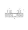
このような流体取扱装置の一例を図1に示す。当該流体取扱装置100は、流体を収容するための収容部12と、当該収容部12に接続され、流体を収容部12に導入するための導入流路13と、当該収容部12に接続され、収容部12内の気体を流体取扱装置100の外部に吸引するための吸引流路14と、を有する。当該流体取扱装置100では、導入流路13に接続された流体供給口16から流体を供給しつつ、吸引流路14に接続された気体吸引口17から収容部12内の気体を吸引する。これにより、収容部12内に負圧が発生し、流体が収容部12内に効率良く収容される。 An example of such a fluid handling device is shown in FIG. The
しかしながら、図1に示すような流体取扱装置100では、気体吸引口17から気体を吸引すると、収容部12内の空気だけでなく、収容部12内に導入される流体も同時に吸引されやすいとの課題があった。従来の流体取扱装置100では、導入流路13の収容部12側開口部、および吸引流路14の収容部12側開口部が、それぞれ収容部12の側面の上端部に形成されている。そのため、導入流路13から収容部12内に吸引された流体が、毛管現象によって収容部12の上縁部(天面と側面とにより形成される角)を伝って吸引流路14の開口部に到達しやすかった。また、導入流路13の収容部12側開口部、および吸引流路14の収容部12側開口部がほぼ同一の高さに形成されていることから、流体が収容部12の側面を伝いやすく、吸引流路14の開口部に到達しやすかった。以上のことから、従来の流体取扱装置100では、流体のロスが多く、所望の量の流体を収容部に効率良く収容することが難しかった。 However, in the
本発明は、このような課題を鑑みてなされたものであり、流体を効率良く、かつロスなく収容部に収容することが可能な流体取扱装置を提供する。 This invention is made | formed in view of such a subject, and provides the fluid handling apparatus which can accommodate a fluid in an accommodating part efficiently and without loss.
本発明に係る流体取扱装置は、流体を収容部に収容させるための流体取扱装置であって、側面および底面を含み、流体を収容させるための収容部と、前記収容部の前記側面に開口部を有し、流体を前記収容部に向けて流動させるための導入流路と、前記収容部内に、前記導入流路の前記開口部と接続するように配置され、前記導入流路からの流体を前記収容部の前記底面に向けて流動させるための流体誘導部と、前記収容部の前記側面に開口部を有し、前記収容部内の空気を吸引するための吸引流路と、を有し、前記吸引流路を介して前記収容部内の空気を吸引することで、流体が前記導入流路および前記流体誘導部を介して前記収容部内に収容される。 A fluid handling device according to the present invention is a fluid handling device for housing a fluid in a housing portion, including a side surface and a bottom surface, a housing portion for housing a fluid, and an opening in the side surface of the housing portion An introduction channel for allowing fluid to flow toward the housing portion, and the inside of the housing portion is connected to the opening of the introduction channel, and the fluid from the introduction channel is A fluid guiding portion for flowing toward the bottom surface of the housing portion, an opening on the side surface of the housing portion, and a suction channel for sucking air in the housing portion, By sucking the air in the housing part through the suction channel, the fluid is housed in the housing part through the introduction channel and the fluid guiding part.
本発明の流体取扱装置によれば、流体を効率良く、かつロスなく収容部に収容することが可能である。 According to the fluid handling device of the present invention, it is possible to store the fluid in the storage section efficiently and without loss.
本発明は、流体を収容部に収容させるための流体取扱装置に関する。本明細書において、「流体」とは、流動性を有し、かつ空気より十分に重い、液体状の物質をいう。具体的には、各種液体や、固体が溶媒に溶解した溶液、固体が分散媒に分散した分散液等を流体として取り扱うことができる。 The present invention relates to a fluid handling apparatus for accommodating a fluid in a container. In this specification, “fluid” refers to a liquid substance that has fluidity and is sufficiently heavier than air. Specifically, various liquids, solutions in which solids are dissolved in a solvent, dispersions in which solids are dispersed in a dispersion medium, and the like can be handled as fluids.
以下、本発明に係る実施の形態について、図面を参照して詳細に説明するが、本発明は、以下の実施の形態に限定されない。 Hereinafter, embodiments according to the present invention will be described in detail with reference to the drawings. However, the present invention is not limited to the following embodiments.
[実施の形態1]
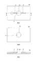
実施の形態1の流体取扱装置を図2に示す。図2Aは、実施の形態1の流体取扱装置200の正面図であり、図2Bは、当該流体取扱装置200の平面図であり、図2Cは右側面図であり、図2Dは、図2BのA−A断面図である。[Embodiment 1]
The fluid handling apparatus of Embodiment 1 is shown in FIG. 2A is a front view of the
図2Dに示すように、本実施の形態の流体取扱装置200は、流体を収容するための収容部22と、流体を流体取扱装置200内部に供給するための流体供給口26と、当該液体供給口26および収容部22に接続され、流体を収容部22に向けて流動させるための導入流路23と、を有する。さらに、流体取扱装置200は、収容部22内部の気体を流体取扱装置200の外部に吸引するための気体吸引口27、ならびに気体吸引口27および収容部22に接続され、収容部22内の気体を吸引するための吸引流路24も有する。また、流体取扱装置200は、収容部22内に、前記導入流路23の開口部と接続され、導入流路23からの流体を収容部22の底面に向けて流動させるための流体誘導部25を有する。本実施の形態の流体取扱装置200では、流体供給口26および気体吸引口27以外の部分から気体や流体が収容部22内に流入、もしくは気体や流体が収容部22内から吸引されないよう、収容部22の気密性が保たれている。 As shown in FIG. 2D, the
ここで、本実施の形態の流体取扱装置200は、図2Aおよび図2Dに示すように、第1基板28aおよび第2基板28bの2つの基板から構成され、上述の収容部22は、第1基板28aが有する第1収容部22aと、第2基板28bが有し、収容部22の底面を含む第2収容部22bと、から構成される。以下、本実施の形態の流体取扱装置200を構成する第1基板28a、および第2基板28bについて説明する。 Here, as shown in FIGS. 2A and 2D, the
(第1基板)
本実施の形態の第1基板28aは、図2Dに示すように、上述の流体供給口26と、導入流路23と、流体誘導部25と、第1収容部22aと、吸引流路24と、気体吸引口27と、を有する。(First substrate)
As shown in FIG. 2D, the
ここで、第1基板28aは一つの部材から構成されていてもよいが、本実施の形態では、製造容易性の観点から、図2Aに示すように、基板本体281および蓋体282から構成されている。図3Aに基板本体281の平面図を示し、図3Bに当該基板本体281の底面図を示し、図3Cに、図3BのB−B断面図を示す。 Here, the
図2Dに示すように、第1基板28aの導入流路23は、一方の端部が蓋体282の流体供給口26と接続され、他方の端部が第1収容部22aの側面に開口している流路である。本実施の形態では、導入流路23は、基板本体281の蓋体282側表面に形成された溝と、この溝の開口部を塞ぐ蓋体282の底面とから構成されている。 As shown in FIG. 2D, the
導入流路23は、図2Dおよび図3Cに示すように、流体取扱装置200の載置面と平行に形成されていてもよいが、導流体取扱装置200の載置面と所定の角度を成すように形成されていてもよい。また、導入流路23は直線状の流路であってもよく、曲線状の流路であってもよい。さらに、導入流路23の断面形状も特に制限されず、半円状や矩形状、円形状等、いずれの形状とすることもできる。また、導入流路23は、流体が導入流路23を満たすことが可能な断面積を有する流路であればよい。 As shown in FIGS. 2D and 3C, the
一方、上記流体誘導部25は、上記導入流路23の第1収容部22aの側面の開口部を覆い、導入流路23の開口部から収容部22内に流入してきた流体を収容部22の底面側に導く部材である。図3A〜図3Cに示すように、本実施の形態の流体誘導部25は、第1収容部22aの側面に配置された略三角柱状の部材であり、導入流路23の開口部側から収容部22の底面側に向かって貫通する貫通孔を有している。本実施の形態の流体取扱装置200では、導入流路23の第1収容部22a側端部(開口部)から収容部22内に流入してきた流体が、当該流体誘導部25の貫通孔を通って収容部22の底面側に移動する。 On the other hand, the
本実施の形態では、流体誘導部25の貫通孔の収容部22底面側の開口部は、第1収容部22aの側面から一定距離、離れた位置に形成される。貫通孔の開口部が、収容部22aの側面(内壁面)と接していると、貫通孔の開口部から排出された流体が、第1収容部22aの側面に付着しやすく、側面を伝って吸引流路24側に移動することがある。これに対し、貫通孔の収容部22底面側の開口部と第1収容部22aの側面とが一定距離離れていると、流体が第1収容部22aの側面に付着し難くなり、重力によって、流体が収容部22の底面方向に移動しやすくなる。このように、本実施の形態では、流体誘導部25の貫通孔の収容部22底面側の開口部は、第1収容部22aの側面から一定距離、離れた位置に形成されるが、本発明はこれに限定されない。貫通孔の開口部が第1収容部22aの側面と接していたとしても、貫通孔の開口部から収容部22に到達した流体が、収容部22の側面上部を周方向に移動するよりも底面側に移動しやすいのであれば、特に問題はない。 In the present embodiment, the opening on the bottom surface side of the
なお、流体誘導部25の貫通孔は、流体を効率良く流動させることができることから、流体取扱装置200の載置面と略垂直に形成されていることが好ましいが、貫通孔は、流体取扱装置200の載置面の垂直方向と一定の角度を成すように形成されていてもよい。 The through hole of the
また、流体誘導部25の貫通孔の大きさは、流体が滞留することなく流動可能な大きさであれば特に制限されない。また、流体誘導部25における貫通孔の長さ(流体誘導部25の高さ)も、流体を収容部22の底面側に向けて流動させることが可能な長さであれば特に制限されない。なお、図3では、流体誘導部25は、略三角柱の部材からなるが、流体誘導部25の形状は当該形状に特に制限されない。例えば半円柱状や角柱状等であってもよい。また、貫通孔の断面形状も、円形に制限されず、半円形状や矩形状等であってもよい。 In addition, the size of the through hole of the
本実施の形態の流体取扱装置200では、収容部22に流体を収容した後、蓋体282側から収容部22にニードル等を挿入し、収容部22内に収容された流体を回収することがあるため、上記流体誘導部25がニードル等の侵入を妨げないことが好ましい。そこで、ニードル等によって、流体誘導部25が収容部22の側面側に屈曲されたり、折り曲げられたりできるよう、流体誘導部25には、切り欠き(図示せず)等が形成されていてもよい。 In the
また、図2Dに示すように、第1基板28aが有する第1収容部22aは、基板本体281に設けられた貫通孔の側面、および蓋体282に囲まれた凹状の空間である。当該第1収容部22aの第2基板28b側の開口部は、後述の第2基板28bの第2収容部22bの開口部と接続される。また、当該第1収容部22aの側面には、前述の流体誘導部25や、吸引流路24の開口部が配置されており、第1収容部22aは、流体誘導部25の貫通孔や、吸引流路24の開口部と連通している。第1収容部22aの形状は、開口部の形状が、第2基板28bの第2収容部22bの開口部の形状と同一であれば特に制限されず、流体の収容量等に応じて適宜選択される。 As shown in FIG. 2D, the
また、上記吸引流路24は、図2Dに示すように、一方の端部が、蓋体282の気体吸引口27と接続され、他方の端部が、第1収容部22aの側面に開口している流路である。本実施の形態では、吸引流路24は、基板本体281の蓋体282側表面に形成された溝と、この溝の開口部を塞ぐ蓋体282の底面とから構成されている。 In addition, as shown in FIG. 2D, the
吸引流路24は、図2Dおよび図3Cに示すように、流体取扱装置200の載置面と平行に形成されていてもよく、流体取扱装置200の載置面と所定の角度を成すように形成されていてもよい。また、吸引流路24は直線状の流路であってもよく、曲線状の流路であってもよい。また、吸引流路24の断面形状は特に制限されず、半円状や矩形状、円形状等、いずれの形状とすることもできる。また、吸引流路24の断面積は、収容部22内の気体を十分に吸引することが可能な大きさであれば特に制限されない。吸引流路24の開口部の断面積を、前述の導入流路23の断面積より大きくすることで、流体が吸引流路24から吸引され難くなる。 2D and 3C, the
また、本実施の形態の流体取扱装置200では、収容部22の底面から前述の流体誘導部25までの距離(ここでは、収容部22の底面から、流体誘導部25の収容部22側開口部までの距離)を、収容部22の底面から吸引流路24の収容部22側の開口部までの距離より短くする。収容部22の底面から前述の流体誘導部25までの距離の方が短いと、流体が収容部22の側面を伝ったとしても、吸引流路24に到達し難く、吸引流路24から吸引され難くなる。 Further, in the
また、上記流体供給口26は、前述の導入流路23と接続され、導入流路23に流体を供給可能であればその形状等は特に制限されない。例えば、液体や固体に含まれる特定の成分のみを導入流路23に供給するためのフィルター(図示せず)等を有していてもよい。またさらに、流体供給口26が、液体を一時的に収容するためのウェルとしても機能してもよい。 The
また、上記気体吸引口27は、前述の吸引流路24と接続され、収容部22内の気体を流体取扱装置200の外部に吸引可能であれば、その構造は特に制限されない。例えば、気体吸引口27は真空ポンプ(図示せず)等と接続可能な形状とすることができる。 Further, the structure of the
ここで、上述の第1基板28aは、流体に対して安定な材料から形成されていればよく、例えば樹脂成形体とすることができる。第1基板28aの作製方法の一例として、基板本体281と蓋体282とをそれぞれ公知の方法で成形し、これらを熱融着や、接着剤(例えば、熱/紫外線硬化性樹脂)等で固定する方法が挙げられる。 Here, the
(第2基板)
第2基板28bは、図2Dに示すように、流体を収容するための第2収容部22bを有していればよい。第2基板28bは、図2Dに示すように、凸状の部材であってもよく、平板状の部材であってもよい。(Second board)
The 2nd board |
第2収容部22bは、第2基板28bに設けられた底面を含む凹状の空間である。当該第2収容部22bの第1基板28a側の開口部は、上述の第1基板28aの第1収容部22aの開口部と接続される。第2収容部22bの形状は、開口部の形状が、第1基板28aの第1収容部22aの開口部の形状と同一であれば特に制限されず、流体の収容量等に応じて適宜選択される。 The second
ここで、第2基板28bは、流体に対して安定な材料から形成されていればよく、例えば樹脂成形体とすることができる。また、第2基板28bは、公知の方法、例えば熱融着や接着剤(例えば、熱/紫外線硬化性樹脂)等で第1基板28aに固定することができる。 Here, the 2nd board |
(流体の収容方法)
本実施の形態の流体取扱装置200により、収容部22に流体を収容する方法を説明する。本実施の形態の流体取扱装置200では、まず、流体供給口26に流体を導入する。そして、気体吸引口27から収容部22内の気体を吸引する。これにより、収容部22内が減圧され、流体供給口26に供給された流体が吸引されて、導入流路23および流体誘導部25を介して収容部22内部に収容される。気体の吸引は、連続的に行ってもよく、断続的に行ってもよい。(Method for containing fluid)
A method for accommodating a fluid in the
(効果)
従来の流体取扱装置100では、図1に示すように、導入流路13の収容部12側の開口部、および吸引流路14の収容部12側の開口部が、それぞれ収容部12の上端に形成されていた。そのため、導入流路13から収容部12内に吸引された流体の一部が、収容部12上縁部を伝わって吸引流路14の開口部に到達し、気体と共に流体取扱装置100の外部に吸引されやすかった。その結果、流体のロスが多くなり、所望の量の流体を効率良く収容部12に収容することが難しかった。(effect)
In the conventional
これに対し、本実施の形態の流体取扱装置200では、図2Dに示すように、導入流路23から吐出される流体を、流体誘導部25によって、収容部22の底面側に誘導する。そのため、流体が、収容部22の上部の壁や上縁部に付着し難く、吸引流路24の開口部に到達し難い。また収容部22において、吸引流路24の開口部が、流体誘導部25の開口部より高い位置に形成されていることから、流体誘導部25から吸引された流体が、収容部22の壁を伝ったとしても、吸引流路24の開口部に到達し難い。したがって、本実施の形態の流体取扱装置200によれば、流体が、流体取扱装置200の外部に吸引され難い。つまり、流体をロスすることなく、収容部22に効率よく収容することが可能である。 On the other hand, in the
[実施の形態2]
実施の形態2の流体取扱装置を図4に示す。図4Aは、実施の形態2の流体取扱装置300の正面図であり、図4Bは、当該流体取扱装置300の平面図であり、図4Cは当該流体取扱装置300の右側面図であり、図4Dは、図4BのA−A断面図である。[Embodiment 2]
A fluid handling apparatus according to the second embodiment is shown in FIG. 4A is a front view of the
図4Dに示すように、本実施の形態の流体取扱装置300は、流体を収容するための収容部32と、流体を流体取扱装置300内部に供給するための流体供給口36と、当該液体供給口36と接続され、流体を収容部32に向けて流動させるための導入流路33と、を有する。さらに、流体取扱装置300は、収容部32内部の気体を流体取扱装置300の外部に吸引するための気体吸引口37、ならびに当該気体吸引口37および収容部32と接続され、収容部32内の気体を吸引するための吸引流路34も有する。また、収容部32内には、導入流路33の開口部と接続され、導入流路33からの流体を収容部32の底面に向けて流動させるための流体誘導部35を有する。本実施形態の流体取扱装置300では、流体供給口36または気体吸引口37以外の部分から収容部32内に気体や流体が流入、もしくは収容部32内から吸引されないよう、収容部32の気密性が保たれている。 As shown in FIG. 4D, the
ここで、本実施の形態の流体取扱装置300は、図4Aおよび図4Dに示すように、第1基板38aおよび第2基板38bの2つの基板から構成されるが、第2の基板38bについては、前述の実施の形態1の第2基板28bと同様とすることができるため、説明を省略する。また、本実施の形態でも、上述の収容部32は、第1基板38aの第1収容部32aと第2基板38bの第2収容部32bとから構成される。以下、本実施の形態の第1基板38aについて説明する。 Here, as shown in FIGS. 4A and 4D, the
(第1基板)
本実施の形態の第1基板38aは、図4Dに示すように、第3基板38cと、連結部材384と、から構成される。当該第3基板38cは、図4Dに示すように、上述の流体供給口36と、導入流路33と、流体誘導部35と、第3収容部32cと、吸引流路34と、気体吸引口37と、を有する。(First substrate)
As shown in FIG. 4D, the
上記第3基板38cは一つの部材から構成されていてもよいが、本実施の形態では、製造容易性の観点から、図4Dに示すように、基板本体381および蓋体382から構成されている。図5Aに基板本体381の平面図、図5Bに当該基板本体381の底面図を示し、図5Cに、図5BのB−B断面図を示す。ここで、第3基板38c(基板本体381および蓋体382)が有する流体供給口36、導入流路33、第3収容部32c、吸引流路34、および気体吸引口37は、実施の形態1の第1基板28a(基板本体281および蓋体282)が有する流体供給口26、導入流路23、第1収容部22a、吸引流路24、および気体吸引口27と同様である。そこで、これらについては説明を省略し、以下、第1の基板38aの流体誘導部35、および連結部材384について説明する。 The
図4Dに示すように、流体誘導部35は、導入流路33の第3収容部32c側の開口部を覆うように配置された筒状の流路である。流体誘導部35は、第3収容部32c内に設けられた第1流体誘導部35a、および連結部材384の嵌合部385内に設けられた第2流体誘導部35bから構成されている。本実施の形態の流体取扱装置300では、導入流路33の第3収容部32c側端部(開口部)から流入した流体が、第1流体誘導部35aおよび第2流体誘導部35bを通って、収容部32の底面側に移動する。 As shown in FIG. 4D, the
流体誘導部35内の流路は、流体を効率良く流動させることができることから、流体取扱装置300の載置面に対して略垂直に形成されていることが好ましいが、流体取扱装置300の載置面の垂直方向と一定の角度を成すように形成されていてもよい。また、第1流体誘導部35aおよび第2流体誘導部35bは、それぞれ、所定の幅の流路を有する部材であればよく、その外形は特に制限されない。 The flow path in the
また、流体誘導部35内の流路の断面積は、流体が滞留することなく流動可能であれば特に制限されず、流体取扱装置300に供給する流体の種類に応じて適宜選択される。また、流体誘導部35内の流路の断面形状も特に制限されず、例えば円形や半円形、矩形等であってもよい。さらに、流体誘導部35の流路長さは、基板本体381の厚みや、連結部材384の厚みに応じて適宜設定される。 The cross-sectional area of the flow path in the
ここで、本実施の形態の流体取扱装置300においても、収容部32の底面から流体誘導部35までの距離(ここでは、収容部32の底面から、第2流体誘導部35の収容部22側開口部までの距離)を、収容部32の底面から吸引流路34の収容部32側の開口部までの距離より短くする。収容部32の底面から前述の流体誘導部35までの距離の方が短いと、流体が収容部32の側面を伝ったとしても、吸引流路34の収容部32側開口部に到達し難く、吸引流路34から吸引され難くなる。 Here, also in the
一方、本実施の形態の連結部材384は、嵌合部385と、嵌合部385内に形成された第4収容部32dと、嵌合部385内に形成された第2流体誘導部35bと、を有する。
嵌合部385は、上述の第3基板38cと、第2基板38bとを連結するための部材であり、嵌合部385は、第3基板38cの第3収容部32c、および第2基板38bの第2収容部32bの内径と同等の外径を有する部材である。嵌合部385の形状は、第3収容部32cおよび第2収容部32bの形状に合わせて適宜選択され、第3収容部32c内に嵌め込むための形状と、第2収容部32b内に嵌め込むための形状は同一であってもよく、異なっていてもよい。On the other hand, the connecting
The
また、第4収容部32dは、嵌合部385内に設けられた貫通孔からなり、第4収容部32dは、第3基板38cの第3収容部32cおよび第2基板の第2収容部32bと接続されて、本実施の形態の流体取扱装置300の収容部32を構成する。前記第3収容部32cの側壁は、嵌合部385を嵌め込むための凹みを有する。そこで、第4収容部32dの第3収容部32c側の開口部は、第3収容部32cの連結部材384側開口部より小さく形成されている。同様に、前記第2収容部32bの側壁は、嵌合部385を嵌め込むための凹みを有する。そこで、第4収容部32dの開口部は、第2収容部32bの第1基板38a側開口部より小さく形成されている。 The fourth storage portion 32d is a through-hole provided in the
また、連結部材384の嵌合部385内には、上述の流体誘導部35の一部を構成する第2流体誘導部35bが配置されている。当該第2流体誘導部35bは、前述のように、流体を流動させるための流路を有していればよく、その形状は特に制限されない。 In addition, a second fluid guiding portion 35 b that constitutes a part of the
ここで、上述の第3基板38cおよび連結部材384は、流体に対して安定な材料から形成されていればよく、第3基板38cは、例えば樹脂成形体とすることができる。第3基板38cの作製方法の一例として、基板本体381と蓋体382とをそれぞれ公知の方法で成形し、これらを融着や、接着剤(例えば、熱/紫外線硬化性樹脂)等で固定する方法が挙げられる。一方、連結部材384は、ゴム等の弾性体からなることが好ましい。連結部材384が弾性を有すると、第2基板38bを、第1基板38aに取り外し可能に取り付けることが可能となる。 Here, the
また、連結部材384の第3基板38cへの取り付けは、連結部材384の嵌合部385を第3基板38cの第3収容部32c内に嵌め込むことで行うことができる。同様に、第2基板38bの第1基板38aの取り付けは、第2基板38bの第2収容部32bに連結部材384の嵌合部385を嵌め込むことで、行うことができる。 Further, the
(流体の収容方法)
本実施の形態の流体取扱装置300でも、流体供給口36内に流体を導入した状態で、気体吸引口37から収容部32内の気体を吸引する。これにより、収容部32内が減圧され、流体供給口36に供給された流体が収容部32内部に効率良く収容される。なお、本実施の形態では、表面張力が大きめの流体を用いることが好ましい。たとえば、本実施の形態では、シリコーンオイル(表面張力:20mN/m程度)を用いることが好ましく、水(表面張力:70mN/m程度)を用いることがより好ましい。このような流体では、導入流路33から収容部32へ到達した流体が毛管現象よって内壁を周方向へ伝わるよりも重力によって底面側へ伝わりやすいため、流体誘導部35と収容部32の壁面との接合部等において、周方向の毛管現象が生じ難く、確実に流体を収容部32に収容することが可能となる。(Method for containing fluid)
Also in the
(効果)
本実施の形態の流体取扱装置300では、図4Dに示すように、導入流路33を通過した流体が、流体誘導部35によって、収容部32の底面側に誘導される。そのため、収容部32内に吸引された流体が、収容部32の上部の壁や縁に付着し難く、吸引流路34の開口部に到達し難い。また、収容部32において、吸引流路34の開口部が、流体誘導部35の開口部より高い位置に形成されていることから、流体誘導部35から吸引された流体が、収容部32の壁を伝ったとしても、吸引流路34の収容部32側開口部に到達し難い。したがって、本実施の形態の流体取扱装置300によれば、流体が、流体取扱装置300の外部に吸引され難い。つまり、流体をロスすることなく、収容部32に効率よく収容することが可能である。(effect)
In the
さらに、本実施の形態の流体取扱装置300では、第1の基板38aに第2の基板38bが着脱可能に取り付けられている。そのため、第2の基板38bの第2収容部32bに収容された流体を容易に回収することができる、との利点もある。 Furthermore, in the
[実施の形態3]
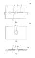
実施の形態3の流体取扱装置を図6に示す。図6Aは、実施の形態3の流体取扱装置400の正面図であり、図6Bは、当該流体取扱装置400の平面図であり、図6Cは当該流体取扱装置400の右側面図であり、図6Dは、図6BのA−A断面図である。[Embodiment 3]
A fluid handling apparatus according to Embodiment 3 is shown in FIG. 6A is a front view of the
図6Aおよび図6Dに示すように、本実施の形態の流体取扱装置400は、流体を収容するための収容部42と、流体を流体取扱装置400内部に供給するための流体供給口46と、当該液体供給口46に接続され、流体を収容部42に向けて流動させるための導入流路43と、を有する。さらに、流体取扱装置400は、収容部42内部の気体を流体取扱装置400の外部に吸引するための気体吸引口47、ならびに当該気体吸引口47および収容部42と接続され、収容部42内の気体を吸引するための吸引流路44も有する。また、収容部42内には、前記導入流路43の開口部と接続され、導入流路43からの流体を収容部42の底面に向けて流動させるための流体誘導部45を有する。本実施の形態の流体取扱装置400では、流体供給口46または気体吸引口47以外の部分から収容部42内に気体や流体が流入、もしくは収容部42内から吸引されないよう、収容部42の気密性が保たれている。 As shown in FIGS. 6A and 6D, the
ここで、本実施の形態の流体取扱装置400は、図6Aおよび図6Dに示すように、基板本体481と、蓋体482との2つの部材から構成されている。図7Aに基板本体481の平面図を示し、図7Bに、当該基板本体481の断面図を示す。 Here, as shown in FIGS. 6A and 6D, the
ここで、本実施の形態の本実施の形態の流体取扱装置400における、流体供給口46、導入流路43、吸引流路44、流体供給口46、および気体吸引口47については、前述の実施の形態1の第1基板28aの流体供給口26、導入流路23、吸引流路24、流体供給口26、および気体吸引口27と同様である。そこで、これらについては説明を省略し、本実施の形態の収容部42および流体誘導部45について説明する。 Here, the
本実施の形態の収容部42は、基板本体481に設けられた凹部の側面および底面と、蓋体482の底面に囲まれた空間である。当該収容部42の側面には、後述の流体誘導部45、導入流路43の開口部、および吸引流路44の開口部が配置されており、収容部42は、導入流路43の開口部、および吸引流路24の開口部と接続されている。ここで、収容部42の形状は、流体を内部に収容可能であれば特に制限されず、流体の収容量等に応じて適宜選択される。 The
一方、本実施の形態の流体誘導部45は、図7Aおよび図7Bに示すように、導入流路43の収容部42側の開口部から、収容部42の底面に向かうように延在する溝である。図7Cに、図7Aの破線部の部分拡大図を示す。図7Bおよび図7Cに示すように、流体誘導部45は、収容部42側に開口を有する溝であり、導入流路43の開口部から流入した流体は、当該流体誘導部45を伝って、収容部42の底面側に移動する。流体誘導部45である溝の深さ(図7Bおよび図7Cにおいてdで表される長さ)は、導入流路43に供給される流体の量に応じて適宜選択される。 On the other hand, as shown in FIG. 7A and FIG. 7B, the
ここで、本実施の形態の流体取扱装置400の基板本体481および蓋体482は、流体に対して安定な材料から形成されていればよく、例えば樹脂成形体とすることができる。本実施の形態の流体取扱装置400の作製方法の一例として、基板本体481と蓋体482とをそれぞれ公知の方法で成形し、これらを融着や、接着剤(例えば、熱/紫外線硬化性樹脂)等で固定する方法が挙げられる。 Here, the substrate
(流体の収容方法)
本実施の形態の流体取扱装置400でも、流体供給口46内に流体を導入した状態で、気体吸引口47から収容部42内の気体を吸引する。これにより、収容部42内が減圧され、流体供給口46に供給された流体が、収容部42内部に効率良く収容される。(Method for containing fluid)
Also in the
(効果)
本実施の形態の流体取扱装置400では、図6Dに示すように、導入流路43を通過した流体が、流体誘導部45によって、収容部42の底面側に誘導される。そのため、収容部42内部に吸引された流体が収容部42の上部の壁や縁に付着し難く、吸引流路44の収容部42側開口部に到達し難い。したがって、本本実施の形態の流体取扱装置400によれば、流体が、流体取扱装置400の外部に吸引され難い。つまり、流体をロスすることなく、収容部42に効率よく収容することが可能である。(effect)
In the
本発明の流体取扱装置によれば、効率良く所望の量の流体を、収容部に収容することが可能である。したがって、本発明の流体取扱装置は、各種、臨床検査や食物検査、環境検査などの様々な用途に使用することができる。 According to the fluid handling device of the present invention, a desired amount of fluid can be efficiently stored in the storage portion. Therefore, the fluid handling apparatus of the present invention can be used for various applications such as various clinical tests, food tests, and environmental tests.
100、200、300、400 流体取扱装置
12、22、32、42 収容部
22a、32a 第1収容部
22b、32b 第2収容部
32c 第3収容部
32d 第4収容部
13、23、33、43 導入流路
14、24、34、44 吸引流路
25、35、45 流体誘導部
16、26、36、46 流体供給口
17、27、37、47 気体吸引口
28a、38a 第1基板
28b、38b 第2基板
38c 第3基板
281、381、481 基板本体
282、382、482 蓋体
384 連結部材
385 嵌合部100, 200, 300, 400
Claims (7)
Translated fromJapanese側面および底面を含み、流体を収容させるための収容部と、
前記収容部の前記側面に開口部を有し、流体を前記収容部に向けて流動させるための導入流路と、
前記収容部内に、前記導入流路の前記開口部と接続するように配置され、前記導入流路からの流体を前記収容部の前記底面に向けて流動させるための流体誘導部と、
前記収容部の前記側面に開口部を有し、前記収容部内の空気を吸引するための吸引流路と、
を有し、
前記吸引流路を介して前記収容部内の空気を吸引することで、流体が前記導入流路および前記流体誘導部を介して前記収容部内に収容される、
流体取扱装置。A fluid handling device for accommodating a fluid in a container,
Containing a side surface and a bottom surface for containing fluid; and
An introduction channel for having an opening on the side surface of the housing part, and for allowing fluid to flow toward the housing part;
A fluid guiding portion that is disposed in the housing portion so as to be connected to the opening portion of the introduction channel, and causes the fluid from the introduction channel to flow toward the bottom surface of the housing portion;
An opening on the side surface of the housing portion, and a suction channel for sucking air in the housing portion;
Have
By sucking the air in the housing part through the suction channel, the fluid is housed in the housing part through the introduction channel and the fluid guiding part.
Fluid handling device.
前記底面を含む第2収容部を有する第2基板と、
が積層された構造を有し、
前記収容部は、前記第1収容部および前記第2収容部から構成される、
請求項1に記載の流体取扱装置。A first substrate having the introduction flow path, the fluid guiding section, the suction flow path, and a first housing section;
A second substrate having a second housing portion including the bottom surface;
Has a laminated structure,
The housing portion is composed of the first housing portion and the second housing portion.
The fluid handling apparatus according to claim 1.
請求項2に記載の流体取扱装置。The second substrate is detachably attached to the first substrate.
The fluid handling apparatus according to claim 2.
前記導入流路、前記流体誘導部、前記吸引流路、および第3収容部、を有する第3基板と、
前記第3基板の前記第3収容部および前記第2基板の前記第2収容部に嵌合する嵌合部、および前記嵌合部内に形成された第4収容部、を有する連結部材と、
を有し、
前記第1収容部は、前記第3収容部および前記第4収容部から構成される、
請求項3に記載の流体取扱装置。The first substrate is
A third substrate having the introduction flow path, the fluid guiding section, the suction flow path, and a third storage section;
A connecting member having a third housing portion of the third substrate and a fitting portion fitted into the second housing portion of the second substrate, and a fourth housing portion formed in the fitting portion;
Have
The first housing part is composed of the third housing part and the fourth housing part,
The fluid handling apparatus according to claim 3.
請求項1〜4のいずれか一項に記載の流体取扱装置。The distance from the bottom surface of the housing portion to the fluid guide portion is shorter than the distance from the bottom surface of the housing portion to the opening portion of the suction channel,
The fluid handling apparatus according to any one of claims 1 to 4.
請求項1〜5のいずれか一項に記載の流体取扱装置。The fluid guiding portion is a flow channel that covers the opening on the housing portion side of the introduction flow channel and extends toward the bottom surface of the housing portion.
The fluid handling apparatus according to any one of claims 1 to 5.
請求項1〜5のいずれか一項に記載の流体取扱装置。The fluid guiding portion is a groove extending from the opening on the housing portion side of the introduction channel toward the bottom surface of the housing portion.
The fluid handling apparatus according to any one of claims 1 to 5.
Priority Applications (4)
| Application Number | Priority Date | Filing Date | Title |
|---|---|---|---|
| JP2016101461AJP6636857B2 (en) | 2016-05-20 | 2016-05-20 | Fluid handling device |
| US16/302,683US20190120867A1 (en) | 2016-05-20 | 2017-05-10 | Fluid handling device |
| EP17799240.1AEP3460485B1 (en) | 2016-05-20 | 2017-05-10 | Fluid handling device |
| PCT/JP2017/017694WO2017199815A1 (en) | 2016-05-20 | 2017-05-10 | Fluid handling device |
Applications Claiming Priority (1)
| Application Number | Priority Date | Filing Date | Title |
|---|---|---|---|
| JP2016101461AJP6636857B2 (en) | 2016-05-20 | 2016-05-20 | Fluid handling device |
Publications (2)
| Publication Number | Publication Date |
|---|---|
| JP2017207429Atrue JP2017207429A (en) | 2017-11-24 |
| JP6636857B2 JP6636857B2 (en) | 2020-01-29 |
Family
ID=60325938
Family Applications (1)
| Application Number | Title | Priority Date | Filing Date |
|---|---|---|---|
| JP2016101461AExpired - Fee RelatedJP6636857B2 (en) | 2016-05-20 | 2016-05-20 | Fluid handling device |
Country Status (4)
| Country | Link |
|---|---|
| US (1) | US20190120867A1 (en) |
| EP (1) | EP3460485B1 (en) |
| JP (1) | JP6636857B2 (en) |
| WO (1) | WO2017199815A1 (en) |
Cited By (2)
| Publication number | Priority date | Publication date | Assignee | Title |
|---|---|---|---|---|
| WO2021193283A1 (en)* | 2020-03-24 | 2021-09-30 | 京セラ株式会社 | Flow path device |
| WO2021193265A1 (en)* | 2020-03-24 | 2021-09-30 | 京セラ株式会社 | Flow path device |
Families Citing this family (2)
| Publication number | Priority date | Publication date | Assignee | Title |
|---|---|---|---|---|
| US20230094429A1 (en)* | 2021-09-30 | 2023-03-30 | Enplas Corporation | Cartridge and liquid handling device |
| WO2024204423A1 (en)* | 2023-03-27 | 2024-10-03 | 京セラ株式会社 | Flow path device and detection device |
Family Cites Families (8)
| Publication number | Priority date | Publication date | Assignee | Title |
|---|---|---|---|---|
| DE19810499A1 (en)* | 1998-03-11 | 1999-09-16 | Microparts Gmbh | Micro-titration plate suitable for a range of automated optical test procedures |
| DE19859693A1 (en)* | 1998-12-23 | 2000-06-29 | Microparts Gmbh | Device for draining a liquid from capillaries |
| WO2005030033A2 (en)* | 2003-09-22 | 2005-04-07 | Battelle Memorial Institute | Fluid sample test device |
| WO2005069737A2 (en)* | 2004-01-27 | 2005-08-04 | Ramot At Tel Aviv University Ltd. | Method and system for detecting analytes |
| JP4490768B2 (en)* | 2004-08-31 | 2010-06-30 | Hoya株式会社 | Biosample container |
| WO2007043619A1 (en)* | 2005-10-13 | 2007-04-19 | Nissui Pharmaceutical Co., Ltd. | Testing device |
| JP4992524B2 (en)* | 2007-04-13 | 2012-08-08 | 株式会社島津製作所 | Reaction vessel plate and reaction processing method |
| US8568668B2 (en)* | 2007-12-10 | 2013-10-29 | Shimadzu Corporation | Micro droplet operation device and reaction processing method using the same |
- 2016
- 2016-05-20JPJP2016101461Apatent/JP6636857B2/ennot_activeExpired - Fee Related
- 2017
- 2017-05-10WOPCT/JP2017/017694patent/WO2017199815A1/ennot_activeCeased
- 2017-05-10USUS16/302,683patent/US20190120867A1/ennot_activeAbandoned
- 2017-05-10EPEP17799240.1Apatent/EP3460485B1/enactiveActive
Cited By (5)
| Publication number | Priority date | Publication date | Assignee | Title |
|---|---|---|---|---|
| WO2021193283A1 (en)* | 2020-03-24 | 2021-09-30 | 京セラ株式会社 | Flow path device |
| WO2021193265A1 (en)* | 2020-03-24 | 2021-09-30 | 京セラ株式会社 | Flow path device |
| JPWO2021193283A1 (en)* | 2020-03-24 | 2021-09-30 | ||
| JP6991407B1 (en)* | 2020-03-24 | 2022-01-13 | 京セラ株式会社 | Channel device |
| JP7361884B2 (en) | 2020-03-24 | 2023-10-16 | 京セラ株式会社 | flow path device |
Also Published As
| Publication number | Publication date |
|---|---|
| WO2017199815A1 (en) | 2017-11-23 |
| US20190120867A1 (en) | 2019-04-25 |
| EP3460485A1 (en) | 2019-03-27 |
| JP6636857B2 (en) | 2020-01-29 |
| EP3460485B1 (en) | 2021-03-31 |
| EP3460485A4 (en) | 2020-01-08 |
Similar Documents
| Publication | Publication Date | Title |
|---|---|---|
| JP6636857B2 (en) | Fluid handling device | |
| US9987630B2 (en) | Fluid handling device and method of using the same | |
| CN110446553A (en) | Fluid container | |
| US20230094356A1 (en) | In-vitro diagnostic analyzer and reagent card | |
| CN104100503A (en) | Fluid injection device and clogging detecting method | |
| US20220105506A1 (en) | Fluid-handling system and cartridge | |
| JP2014097485A (en) | Liquid handling apparatus | |
| KR101732576B1 (en) | Dual syringe typed disposable viscosity measuring kit assembly for blood | |
| JP2013011577A (en) | System and method for dispensing fluid from container into fluid receptacle | |
| KR101476924B1 (en) | Viscosity measuring kit for blood | |
| US20220055028A1 (en) | Fluid handling system | |
| US11311881B2 (en) | Fluid handling method, fluid handling device used in same, and fluid handling system | |
| CN112292602B (en) | Measuring tool and liquid feeding method | |
| JP7036126B2 (en) | Fluid device and flow path supply system | |
| WO2020178951A1 (en) | Fluid handling device | |
| JP2010217145A (en) | Microchip and microchip set | |
| JP5140620B2 (en) | Liquid sample storage device and liquid sample measurement method | |
| US20220401948A1 (en) | Fluid handling device | |
| US20250065327A1 (en) | Biochip Coupling Systems and Devices | |
| EP4245414A1 (en) | Biochip coupling systems and devices | |
| JP2022045741A (en) | Liquid handling device | |
| CN114126760A (en) | Microfluidic chip, liquid adding method thereof and microfluidic system | |
| JPWO2019151070A1 (en) | Cartridge and fluid handling system including it | |
| CN118076809A (en) | Containers, microfluidic devices, and diaphragm pumps | |
| JP2023150202A (en) | Interface and fluid handling device |
Legal Events
| Date | Code | Title | Description |
|---|---|---|---|
| A621 | Written request for application examination | Free format text:JAPANESE INTERMEDIATE CODE: A621 Effective date:20190403 | |
| RD02 | Notification of acceptance of power of attorney | Free format text:JAPANESE INTERMEDIATE CODE: A7422 Effective date:20190617 | |
| A131 | Notification of reasons for refusal | Free format text:JAPANESE INTERMEDIATE CODE: A131 Effective date:20191001 | |
| RD04 | Notification of resignation of power of attorney | Free format text:JAPANESE INTERMEDIATE CODE: A7424 Effective date:20191030 | |
| A521 | Request for written amendment filed | Free format text:JAPANESE INTERMEDIATE CODE: A523 Effective date:20191129 | |
| TRDD | Decision of grant or rejection written | ||
| A01 | Written decision to grant a patent or to grant a registration (utility model) | Free format text:JAPANESE INTERMEDIATE CODE: A01 Effective date:20191217 | |
| A61 | First payment of annual fees (during grant procedure) | Free format text:JAPANESE INTERMEDIATE CODE: A61 Effective date:20191219 | |
| R150 | Certificate of patent or registration of utility model | Ref document number:6636857 Country of ref document:JP Free format text:JAPANESE INTERMEDIATE CODE: R150 | |
| LAPS | Cancellation because of no payment of annual fees |