JP2017205324A - robot - Google Patents
robotDownload PDFInfo
- Publication number
- JP2017205324A JP2017205324AJP2016100222AJP2016100222AJP2017205324AJP 2017205324 AJP2017205324 AJP 2017205324AJP 2016100222 AJP2016100222 AJP 2016100222AJP 2016100222 AJP2016100222 AJP 2016100222AJP 2017205324 AJP2017205324 AJP 2017205324A
- Authority
- JP
- Japan
- Prior art keywords
- robot
- user
- image
- recognition
- frame
- Prior art date
- Legal status (The legal status is an assumption and is not a legal conclusion. Google has not performed a legal analysis and makes no representation as to the accuracy of the status listed.)
- Withdrawn
Links
Images


Classifications
- B—PERFORMING OPERATIONS; TRANSPORTING
- B25—HAND TOOLS; PORTABLE POWER-DRIVEN TOOLS; MANIPULATORS
- B25J—MANIPULATORS; CHAMBERS PROVIDED WITH MANIPULATION DEVICES
- B25J5/00—Manipulators mounted on wheels or on carriages
- A—HUMAN NECESSITIES
- A63—SPORTS; GAMES; AMUSEMENTS
- A63H—TOYS, e.g. TOPS, DOLLS, HOOPS OR BUILDING BLOCKS
- A63H11/00—Self-movable toy figures
- A—HUMAN NECESSITIES
- A63—SPORTS; GAMES; AMUSEMENTS
- A63H—TOYS, e.g. TOPS, DOLLS, HOOPS OR BUILDING BLOCKS
- A63H33/00—Other toys
- A63H33/005—Motorised rolling toys
- B—PERFORMING OPERATIONS; TRANSPORTING
- B25—HAND TOOLS; PORTABLE POWER-DRIVEN TOOLS; MANIPULATORS
- B25J—MANIPULATORS; CHAMBERS PROVIDED WITH MANIPULATION DEVICES
- B25J11/00—Manipulators not otherwise provided for
- B25J11/0005—Manipulators having means for high-level communication with users, e.g. speech generator, face recognition means
- B25J11/0015—Face robots, animated artificial faces for imitating human expressions
- B—PERFORMING OPERATIONS; TRANSPORTING
- B25—HAND TOOLS; PORTABLE POWER-DRIVEN TOOLS; MANIPULATORS
- B25J—MANIPULATORS; CHAMBERS PROVIDED WITH MANIPULATION DEVICES
- B25J13/00—Controls for manipulators
- B25J13/003—Controls for manipulators by means of an audio-responsive input
- B—PERFORMING OPERATIONS; TRANSPORTING
- B25—HAND TOOLS; PORTABLE POWER-DRIVEN TOOLS; MANIPULATORS
- B25J—MANIPULATORS; CHAMBERS PROVIDED WITH MANIPULATION DEVICES
- B25J9/00—Programme-controlled manipulators
- B25J9/16—Programme controls
- B25J9/1694—Programme controls characterised by use of sensors other than normal servo-feedback from position, speed or acceleration sensors, perception control, multi-sensor controlled systems, sensor fusion
- B25J9/1697—Vision controlled systems
- G—PHYSICS
- G10—MUSICAL INSTRUMENTS; ACOUSTICS
- G10L—SPEECH ANALYSIS TECHNIQUES OR SPEECH SYNTHESIS; SPEECH RECOGNITION; SPEECH OR VOICE PROCESSING TECHNIQUES; SPEECH OR AUDIO CODING OR DECODING
- G10L15/00—Speech recognition
- G10L15/22—Procedures used during a speech recognition process, e.g. man-machine dialogue
- H—ELECTRICITY
- H04—ELECTRIC COMMUNICATION TECHNIQUE
- H04R—LOUDSPEAKERS, MICROPHONES, GRAMOPHONE PICK-UPS OR LIKE ACOUSTIC ELECTROMECHANICAL TRANSDUCERS; DEAF-AID SETS; PUBLIC ADDRESS SYSTEMS
- H04R1/00—Details of transducers, loudspeakers or microphones
- H04R1/02—Casings; Cabinets ; Supports therefor; Mountings therein
- H04R1/028—Casings; Cabinets ; Supports therefor; Mountings therein associated with devices performing functions other than acoustics, e.g. electric candles
- A—HUMAN NECESSITIES
- A63—SPORTS; GAMES; AMUSEMENTS
- A63H—TOYS, e.g. TOPS, DOLLS, HOOPS OR BUILDING BLOCKS
- A63H2200/00—Computerized interactive toys, e.g. dolls
- G—PHYSICS
- G10—MUSICAL INSTRUMENTS; ACOUSTICS
- G10L—SPEECH ANALYSIS TECHNIQUES OR SPEECH SYNTHESIS; SPEECH RECOGNITION; SPEECH OR VOICE PROCESSING TECHNIQUES; SPEECH OR AUDIO CODING OR DECODING
- G10L15/00—Speech recognition
- G10L15/22—Procedures used during a speech recognition process, e.g. man-machine dialogue
- G10L2015/223—Execution procedure of a spoken command
- Y—GENERAL TAGGING OF NEW TECHNOLOGICAL DEVELOPMENTS; GENERAL TAGGING OF CROSS-SECTIONAL TECHNOLOGIES SPANNING OVER SEVERAL SECTIONS OF THE IPC; TECHNICAL SUBJECTS COVERED BY FORMER USPC CROSS-REFERENCE ART COLLECTIONS [XRACs] AND DIGESTS
- Y10—TECHNICAL SUBJECTS COVERED BY FORMER USPC
- Y10S—TECHNICAL SUBJECTS COVERED BY FORMER USPC CROSS-REFERENCE ART COLLECTIONS [XRACs] AND DIGESTS
- Y10S901/00—Robots
- Y10S901/01—Mobile robot
- Y—GENERAL TAGGING OF NEW TECHNOLOGICAL DEVELOPMENTS; GENERAL TAGGING OF CROSS-SECTIONAL TECHNOLOGIES SPANNING OVER SEVERAL SECTIONS OF THE IPC; TECHNICAL SUBJECTS COVERED BY FORMER USPC CROSS-REFERENCE ART COLLECTIONS [XRACs] AND DIGESTS
- Y10—TECHNICAL SUBJECTS COVERED BY FORMER USPC
- Y10S—TECHNICAL SUBJECTS COVERED BY FORMER USPC CROSS-REFERENCE ART COLLECTIONS [XRACs] AND DIGESTS
- Y10S901/00—Robots
- Y10S901/46—Sensing device
- Y10S901/47—Optical
Landscapes
- Engineering & Computer Science (AREA)
- Mechanical Engineering (AREA)
- Robotics (AREA)
- Multimedia (AREA)
- Health & Medical Sciences (AREA)
- Audiology, Speech & Language Pathology (AREA)
- Human Computer Interaction (AREA)
- Acoustics & Sound (AREA)
- Physics & Mathematics (AREA)
- General Health & Medical Sciences (AREA)
- Signal Processing (AREA)
- Computational Linguistics (AREA)
- Manipulator (AREA)
- Toys (AREA)
Abstract
Description
Translated fromJapanese本開示は、ユーザと対話するロボットに関する。 The present disclosure relates to a robot that interacts with a user.
従来から種々のロボットが提案されている。 Conventionally, various robots have been proposed.
特許文献1は、コミュニケーションロボットを開示する。特許文献1では、前記ロボットは、入力音声について音声認識部が算出した信頼度に基づいて前記入力音声に対して回答できないことを示す回答不能行動を行うか否かを判定し、前記回答不能行動を行うと判定した場合、前記コミュニケーションロボットが可能な所定の応答行動から、例えば、首をかしげるなど前記回答不能行動を選択する。これにより、独り言、未知語または音声以外の残音を音声と認識して誤って発話することを防止する(例えば、段落[0004]から[0007]、[0113])。
特許文献2は、ロボット制御装置に関する。特許文献2では、ロボットは、マイクから入力された音声を音声認識部で認識し、その音声認識が失敗したり、その信頼性が低い場合、例えば、ロボットに首をかしげたり、耳に手を当てるなどの所定の行動を行う(例えば、段落[0003]から[0005])。
上記の従来技術では、更なる改善が必要とされていた。 In the above prior art, further improvement has been required.
上記課題を解決するために、本開示の一態様のロボットは、
球体状の筐体と、
前記筐体の内側部に配置されたフレームと、
前記フレームに備え付けられた入力装置と、
前記フレームに備え付けられた出力装置と、
前記フレームに備え付けられ、外部ネットワークに接続される通信回路と、
前記フレームに備え付けられ、前記筐体の内周面に接して前記筐体を回転させる一組の駆動輪と、
前記入力装置を介して入力したユーザの入力指示に対して、所定時間以上を要する所定の処理に基づいて応答する場合、前記一組の駆動輪をそれぞれ逆方向に回転させて前記球体状の筐体を回転させ、
前記出力装置を介して前記所定の処理に基づく応答を出力させるとき、前記一組の駆動輪による前進方向を前記ユーザに向けて前記球体状の筐体の回転を停止させる制御回路と、を備えたものである。In order to solve the above problem, a robot according to one embodiment of the present disclosure is provided.
A spherical housing;
A frame disposed on the inner side of the housing;
An input device provided in the frame;
An output device provided in the frame;
A communication circuit provided in the frame and connected to an external network;
A set of drive wheels provided on the frame and rotating the housing in contact with an inner peripheral surface of the housing;
When responding to a user input instruction input via the input device based on a predetermined process that requires a predetermined time or more, the pair of driving wheels are rotated in the opposite directions, respectively, so that the spherical housing is Rotate the body,
A control circuit for stopping the rotation of the spherical casing with the forward direction of the set of driving wheels directed to the user when outputting a response based on the predetermined process via the output device. It is a thing.
上記態様により、更なる改善を実現できた。 According to the above aspect, further improvement can be realized.
(本開示に係る一態様を発明するに至った経緯)
まず、本開示に係る一態様をするに至った着眼点について説明する。(Background to inventing one aspect of the present disclosure)
First, the point of focus that has led to one aspect of the present disclosure will be described.
特許文献1は、2足歩行の人型ロボットを開示するものである。そして、このロボットは、頭部、腕部、脚部、胴部などを備えている。そのため、前記ロボットは、入力した音声の認識結果に基づいて、頭部、腕部、脚部、胴部を動作させて、ユーザの音声に対して応答させることができる。
特許文献2は、犬型のペットロボットに関するものである。そして、前記ペットロボットは、胴体部分に、頭部、4つの脚部、尻尾などを備えている。そのため、前記ペットロボットは、入力した音声の認識結果に基づいて、頭部、4つの脚部、尻尾を動作させて、ユーザの音声に対して応答させることができる。
このように、各種のロボットは、ユーザからの問いに対して応答する機能を備えている。上記特許文献1又は2のように、音声認識を用いてユーザからの問いに対して応答する場合、ユーザの発話からロボットの応答までの時間間隔を、前記ユーザと前記ロボットとの間の会話が途切れたと前記ユーザに思わせない程度に短く設定する必要がある。そのため、音声の認識結果の信頼度が高い又は低いに関わらず、前記ユーザの発話から比較的短時間で前記ロボットは応答するように設計されていると考えられる。 As described above, various robots have a function of responding to questions from users. When responding to a question from a user using speech recognition as in
これに対して、ユーザの発話からロボットの応答までの時間間隔が比較的長くなる場合がある。一例として、ユーザが持っている対象物が何であるのかをロボットに問い合わせ、前記ロボットが画像認識機能を用いて応答する場合が考えられる。 On the other hand, the time interval from the user's utterance to the robot response may be relatively long. As an example, a case may be considered in which a robot is inquired about what the user has and the robot responds using an image recognition function.
ユーザの問いに対して前記ロボットが画像認識機能を用いて応答する場合、前記対象物を撮像し、その後、例えば、前記撮像された画像を、画像認識用の機能を有するクラウドサーバに送信し、前記クラウドサーバにおいて前記画像を認識し、前記認識された認識結果を前記クラウドサーバから受信し、前記受信した認識結果に基づいて前記対象物が何であるかを回答させることが考えられる。この場合、前記ユーザが前記ロボットに問い合わせをしてから、前記ロボットが前記ユーザに回答するまでの時間が、例えば15秒程度要すると、前記ロボットは回答するのに前記ユーザを待たせることになる。 When the robot responds to a user's question using an image recognition function, the target object is imaged, and then, for example, the captured image is transmitted to a cloud server having a function for image recognition, It is conceivable that the cloud server recognizes the image, receives the recognized recognition result from the cloud server, and makes a reply as to what the object is based on the received recognition result. In this case, if it takes about 15 seconds for the robot to answer the user after the user makes an inquiry to the robot, the robot waits for the user to answer. .
このように、前記ロボットが前記ユーザの問いに応答できない時間が所定秒以上続くと、前記ユーザは、前記ロボットの外観だけからは、前記ロボットが処理中なのか又は故障により動かないのか判断できないという課題がある。 Thus, if the time during which the robot cannot respond to the user's question continues for a predetermined time or more, the user cannot determine from the appearance of the robot alone whether the robot is processing or does not move due to a failure. There are challenges.
また、上記特許文献1又は2とは異なり、手、足、首などを有しない球体状のロボットを想定した場合、手足を動かしたり、首をかしげたりして前記ロボットが処理中であることを前記ユーザに対して伝えることはできない。また、処理中であることを示す表示を前記球体状のロボットの表面にすることが考えられるが、手、足、首などを有しない球体状のロボットの表面にその旨の表示をすると、前記球体状のロボットの顔に、顔と要素とは異なる表示がされることになって、前記ロボットの顔としては不自然になる。 Also, unlike the above-mentioned
このように、手、足、首などを有しない球体状のロボットの場合、前記ユーザに対して内部処理の進行状況を前記ユーザに伝えるのに制約があるという課題がある。 As described above, in the case of a spherical robot having no hands, feet, necks, etc., there is a problem that there is a restriction in transmitting the progress of internal processing to the user.
以上の考察により、本発明者は、以下の本開示に係る各態様を想到するに至った。 Based on the above considerations, the present inventor has come up with the following aspects of the present disclosure.
本開示の一態様のロボットは、
球体状の筐体と、
前記筐体の内側部に配置されたフレームと、
前記フレームに備え付けられた入力装置と、
前記フレームに備え付けられた出力装置と、
前記フレームに備え付けられ、外部ネットワークに接続される通信回路と、
前記フレームに備え付けられ、前記筐体の内周面に接して前記筐体を回転させる一組の駆動輪と、
前記入力装置を介して入力したユーザの入力指示に対して、所定時間以上を要する所定の処理に基づいて応答する場合、前記一組の駆動輪をそれぞれ逆方向に回転させて前記球体状の筐体を回転させ、
前記出力装置を介して前記所定の処理に基づく応答を出力させるとき、前記一組の駆動輪による前進方向を前記ユーザに向けて前記球体状の筐体の回転を停止させる制御回路と、を備えたものである。A robot according to an aspect of the present disclosure
A spherical housing;
A frame disposed on the inner side of the housing;
An input device provided in the frame;
An output device provided in the frame;
A communication circuit provided in the frame and connected to an external network;
A set of drive wheels provided on the frame and rotating the housing in contact with an inner peripheral surface of the housing;
When responding to a user input instruction input via the input device based on a predetermined process that requires a predetermined time or more, the pair of driving wheels are rotated in the opposite directions, respectively, so that the spherical housing is Rotate the body,
A control circuit for stopping the rotation of the spherical casing with the forward direction of the set of driving wheels directed to the user when outputting a response based on the predetermined process via the output device. It is a thing.
本態様によると、前記入力装置を介して入力したユーザの入力指示に対して、所定時間以上を要する所定の処理に基づいて応答する場合、前記一組の駆動輪をそれぞれ逆方向に回転させて前記球体状の筐体を回転させる。これにより、前記球体状のロボットの形状を利用して、前記ユーザとの対話中に前記筐体の回転により前記ロボットが処理中であることを前記ユーザに伝えることができる。 According to this aspect, when responding to a user input instruction input via the input device based on a predetermined process that requires a predetermined time or more, the pair of driving wheels are respectively rotated in the opposite directions. The spherical housing is rotated. Thus, the shape of the spherical robot can be used to inform the user that the robot is processing by rotating the housing during the dialogue with the user.
また、前記認識結果を受信した場合、単に前記球体状の筐体の回転を停止させるだけであると、前記ロボットの前進方向が正面であるとすると、前記ロボットが正面を前記ユーザに向けていない状態で前記ロボットが停止することがある。 In addition, when the recognition result is received, the robot does not point the front to the user if the forward direction of the robot is the front if the rotation of the spherical housing is merely stopped. The robot may stop in a state.
本態様によると、前記出力装置を介して前記所定の処理に基づく応答を出力させるとき、前記一組の駆動輪による前進方向を前記ユーザに向けて前記球体状の筐体の回転を停止させる。これにより、前記所定の処理の結果に基づく応答を前記ユーザに向けて出力させることができる。そのため、前記ロボットの正面が前記ユーザの向けられていない状態で、前記所定の処理の結果に基づく応答を出力する不都合を防止できる。 According to this aspect, when outputting the response based on the predetermined process via the output device, the rotation of the spherical casing is stopped with the forward direction of the set of driving wheels directed toward the user. Thereby, the response based on the result of the predetermined process can be output to the user. Therefore, it is possible to prevent the inconvenience of outputting a response based on the result of the predetermined processing in a state where the front of the robot is not directed to the user.
(実施の形態)
以下、本発明の各実施の形態について、図面を参照しながら説明する。尚、各図面において、同じ構成要素については同じ符号が用いられている。(Embodiment)
Hereinafter, embodiments of the present invention will be described with reference to the drawings. In the drawings, the same reference numerals are used for the same components.
(第1の実施の形態)
(全体構成)
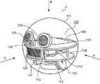
図1は、本開示の第1の実施の形態に係るロボット1の外観斜視図である。ロボット1は、図1に示すように、球体状の筐体101を備える。筐体101は例えば、透明な部材或いは半透明の部材で構成される。(First embodiment)
(overall structure)
FIG. 1 is an external perspective view of the
図2は、本開示の第1の実施の形態に係るロボット1の内部斜視図である。 FIG. 2 is an internal perspective view of the
図2において、フレーム102が筐体101の内側部に配置されている。フレーム102は、第1回転板103及び第2回転板104を備える。第1回転板103は、第2回転板104に対して上方に位置している。 In FIG. 2, the
図2に示すように、第1表示部105及び第2表示部106は、第1回転板103の上面に備え付けられている。また、第3表示部107は第2回転板104の上面に備え付けられている。第1表示部105、第2表示部106及び第3表示部107は、例えば、複数の発光ダイオードにより構成される。第1表示部105、第2表示部106及び第3表示部107は、ロボットの表情の表示情報を表示する。具体的には、第1表示部105、第2表示部106及び第3表示部107は、前記複数の発光ダイオードの点灯を個別に制御することにより、図1に示すように、ロボット1の顔の一部、例えば、目や口を表示する。図1の例では、第1表示部105が左目の画像を表示し、第2表示部106が右目の画像を表示し、第3表示部107が口の画像を表示している。そして、左目、右目、口の画像は、透明又は半透明の部材からなる筐体101を透過し、外部に放射されている。 As shown in FIG. 2, the
カメラ108は、図2に示すように、第1回転板103の上面に備え付けられている。カメラ108は、ロボット1の周辺環境の映像を取得する。カメラ108は、図1に示すように、ロボット1の顔の一部、例えば、鼻を構成する。したがって、カメラ108の光軸はロボット1の前方に向かうことになる。これにより、カメラ108は正面に差し出された認識対象物を撮影できる。 As shown in FIG. 2, the
制御回路109は、図2に示すように、第1回転板103の上面に備え付けられている。制御回路109は、ロボット1の各種動作を制御する。制御回路109の詳細は、図16を参照しながら後述する。 The
第1駆動輪110及び第2駆動輪111は、それぞれ、第2回転板104の下面に備え付けられており、筐体101の内周面に接している。また、第1駆動輪110は、第1駆動輪110を駆動させる第1モータ112を有する。同様に、第2駆動輪111は、第2駆動輪111を駆動させる第2モータ113を有する。即ち、第1駆動輪110及び第2駆動輪111は、それぞれ独立した個別のモータによって駆動される。第1駆動輪110及び第2駆動輪111の駆動によるロボット1の動作の詳細は後述する。第1駆動輪110及び第2駆動輪111は、一組の駆動輪を構成する。 The
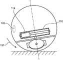
図3は、図2のA視における、本開示の第1の実施の形態に係るロボット1の内部側面図である。図3において、カウンターウェイト114(重りの一例)は、第1回転板103と第2回転板104との間に設けられている。カウンターウェイト114は、筐体101の中心からやや下方に位置する。このため、ロボット1の重心は、筐体101の中心から下方に位置する。これにより、ロボット1の動作を安定させることができる。 FIG. 3 is an internal side view of the
図3に示すように、ロボット1は、カウンターウェイト114を駆動する機構として、カウンターウェイト114の移動方向を規定するガイドシャフト115、カウンターウェイト114の回転方向の位置を規定するスイングアーム116、スイングアーム116を回転させる回転用モータ117、スイングアーム116及び回転用モータ117の間を接続する回転シャフト118、カウンターウェイト114の駆動に用いられるベルト119(図8A及び図8B)、ベルト119に接するモータプーリ120(図8A及び図8B)、及び、モータプーリ120を回転させる、図示しない重り駆動用モータを備える。尚、本態様においては、前記駆動用モータはカウンターウェイト114に内蔵されている。カウンターウェイト114の駆動によるロボット1の動作の詳細は後述する。 As shown in FIG. 3, the
回転シャフト118は、第1駆動輪110と第2駆動輪111との駆動軸に対して垂直方向に延びる。回転シャフト118は、フレーム102に備え付けられたシャフトの一例に相当する。第1駆動輪110及び第2駆動輪111は正面視において、地面に向けて距離が離れるように取り付けられている。この場合、第1駆動輪110と第2駆動輪111との駆動軸は、例えば、第1駆動輪110と第2駆動輪111との中心同士を結ぶ仮想的な軸線である。なお、第1駆動輪110と第2駆動輪111とが正面視において平行に取り付けられていれば、実際の駆動軸が第1駆動輪110と第2駆動輪111との駆動軸となる。 The
ロボット1は、図略の電源及びマイク217(図16)をさらに備える。ロボット1は、図略の充電器により充電される。マイク217は、ロボット1の周辺環境の音声を取得する。 The
次に、第1駆動輪110及び第2駆動輪111を用いたロボット1の動作を図4から図6を参照して説明する。 Next, the operation of the
図4は、図2のA視における、本開示の第1の実施の形態に係るロボット1の直進動作を表す側面図である。図5は、図2のB視における、本開示の第1の実施の形態に係るロボット1の回転動作を表す平面図である。図6は、本開示の第1の実施の形態に係るロボット1の回転動作を表す斜視図である。 FIG. 4 is a side view illustrating the straight-ahead operation of the
図4に示すように、第1駆動輪110及び第2駆動輪111を前方方向に回転させると、その動力によって筐体101は前方方向に回転する。これにより、ロボット1は前進する。逆に、第1駆動輪110及び第2駆動輪111を後方方向に回転させると、ロボット1は後進する。 As shown in FIG. 4, when the
また、図5及び図6に示すように、第1駆動輪110及び第2駆動輪111を互いに逆方向に回転させると、その動力によって筐体101は、その中心を通過する鉛直軸回りの回転動作を行う。即ち、ロボット1は、その場で左回り又は右回りに回転する。ロボット1は、このような前進、後進又は回転動作によって移動する。 Further, as shown in FIGS. 5 and 6, when the
次に、カウンターウェイト114を用いたロボット1の基本動作を図7から図9Cを参照して説明する。 Next, the basic operation of the
図7は、図3の側面図において重り駆動機構を示した図である。図8Aは、カウンターウェイト114を所定の直線方向に駆動する際のカウンターウェイト114の駆動機構の動作を示す斜視図である。図8Bは、カウンターウェイト114を所定の直線方向に駆動する際のカウンターウェイト114の駆動機構の動作を示す側面図である。図8Cは、図3の側面図においてカウンターウェイト114が所定の直線方向に往復移動する状態を示す側面図である。図9Aは、スイングアーム116を回転させる際のカウンターウェイト114の駆動機構の動作を示す斜視図である。図9Bは、スイングアーム116を回転させる際の重り駆動機構の動作を示す側面図である。図9Cは、図2のB視における、本開示の第1の実施の形態に係るロボット1のスイングアーム116が回転する状態を示す平面図である。 FIG. 7 is a view showing a weight driving mechanism in the side view of FIG. FIG. 8A is a perspective view showing the operation of the drive mechanism of the
図7に示すように、例えば、スイングアーム116の中央位置がカウンターウェイト114のデフォルト位置である。カウンターウェイト114がスイングアーム116の中央に位置しているとき、第1回転板103及び第2回転板104は走行面とほぼ平行になり、ロボット1の顔を構成する、例えば、目、鼻、口がデフォルト方向に向いた状態になる。 As shown in FIG. 7, for example, the center position of the
図8A及び図8Bに示すように、カウンターウェイト114に内蔵された、図示しない重り駆動用モータは、前記重り駆動用モータに連結されたモータプーリ120を回転させる。回転されたモータプーリ120がベルト119上を転がることにより、カウンターウェイト114はスイングアーム116内を移動する。モータプーリ120の回転方向、即ち、前記重り駆動用モータの駆動方向を変化させることにより、スイングアーム116内において、カウンターウェイト114は直線方向に往復移動する。 As shown in FIGS. 8A and 8B, a weight driving motor (not shown) built in the
図8Cに示すように、カウンターウェイト114は、ガイドシャフト115に沿って、スイングアーム116内を直線方向に往復移動する。 As shown in FIG. 8C, the
図9A及び図9Bに示すように、回転用モータ117は、回転シャフト118を回転させることにより、回転シャフト118(図3)に接続されたスイングアーム116を回転させる。 As shown in FIGS. 9A and 9B, the
図9Cに示すように、スイングアーム116は時計回り、反時計回りのいずれの方向にも回転させることができる。 As shown in FIG. 9C, the
さらに、カウンターウェイト114を用いたロボット1の動作の詳細を図10から図13を参照して説明する。図10は、図2のA視における、カウンターウェイト114が前方寄りに位置しているときのロボット1の姿勢を示す側面図である。図11は、図2のA視における、カウンターウェイト114が後方寄りに位置しているときのロボット1の姿勢を示す側面図である。図12は、図2のC視における、カウンターウェイト114が右方寄りに位置しているときのロボット1の姿勢を示す正面図である。図13は、図2のC視における、カウンターウェイト114が左方寄りに位置しているときのロボット1の姿勢を示す正面図である。 Further, details of the operation of the
図10に示すように、スイングアーム116がロボット1の正面に対して垂直な状態で、カウンターウェイト114を、デフォルト位置からスイングアーム116の一端(図10では左端)、即ち、前方寄りに移動させると、ロボット1は、矢印121が示すように前方に傾く。また、図11に示すように、スイングアーム116がロボット1の正面に対して垂直な状態で、カウンターウェイト114を、デフォルト位置からスイングアーム116の他端(図11では右端)、即ち、後方寄りに移動させると、ロボット1は、矢印122が示すように後方に傾く。従って、スイングアーム116がロボット1の正面に対して垂直な状態で、カウンターウェイト114をスイングアーム116内の前記一端から前記他端まで往復動作させると、ロボット1は、矢印121が示す前方または矢印122が示す後方に傾く往復動作を行う。即ち、ロボット1は所定の角度において上下方向に回転する。 As shown in FIG. 10, with the
上述のように、第1表示部105、第2表示部106及び第3表示部107は、ロボット1の顔の一部、例えば、目や口を表す。従って、カウンターウェイト114を用いてロボット1に前方または後方に傾く往復動作をさせることにより、例えば、ロボット1が息切れしている状態又は眠い状態を表現することができる。この制御を、例えば、電源の電力残量が所定値以下になった場合に行えば、ロボット1は、第1表示部105、第2表示部106、及び第3表示部107に前記顔とは無関係な電力残量に関する情報を表示することなく、電源の電力残量が少なくなっていることをユーザに違和感なく伝えることができる。 As described above, the
図12に示すように、スイングアーム116がロボット1の正面に対して平行な状態で、カウンターウェイト114を、デフォルト位置からスイングアーム116の一端(図12の右端)、即ち、右方寄りに移動させると、ロボット1は、矢印123が示す右側に傾く。また、図13に示すように、スイングアーム116がロボット1の正面に対して平行な状態で、カウンターウェイト114を、デフォルト位置からスイングアーム116の他端(図13の左端)、即ち、左方寄りに移動させると、ロボット1は、矢印124が示す左側に傾く。従って、スイングアーム116をロボット1の正面に対して平行な状態で、カウンターウェイト114をスイングアーム116内の前記一端から前記他端まで往復動作させると、ロボット1は、矢印123が示す右側または矢印124が示す左側に傾く往復動作を行う。即ち、ロボット1は所定の角度において左右方向に回転する。 As shown in FIG. 12, with the
上述のように、第1表示部105、第2表示部106、及び第3表示部107は、ロボット1の顔の一部、例えば、目や口を表す。従って、カウンターウェイト114を用いてロボット1に右方または左方に傾く往復運動をさせることにより、例えば、ロボット1の機嫌がよい状態を表現し又はロボット1が考え中であることを表現できる。 As described above, the
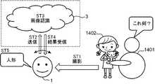
図14は、本開示の第1の実施の形態に係るロボット1のユースケースの一例を示す図である。図14に示すように、ロボット1はクラウドサーバ3に接続されている。ユーザ1401は、女の子の人形1402をロボット1の正面に差し出し、「これ何?」と発話する。すると、ロボット1は、ユーザ1401の発話内容から、ユーザ1401が認識対象物の認識要求を行ったと判断し、認識対象物の画像を撮影する(ステップST1)。 FIG. 14 is a diagram illustrating an example of a use case of the
次に、ロボット1は、撮影した認識対象物の画像をクラウドサーバ3に送信する(ステップST2)。次に、クラウドサーバ3は、画像認識処理を行い、送信された画像に含まれている認識対象物が人形1402であると認識する(ステップST3)。次に、クラウドサーバ3は、画像認識結果をロボット1に送信し、ロボット1は、画像認識結果を受信する(ステップST4)。次に、ロボット1は、画像認識結果が「人形」であるので、「人形」と発話する(ステップST5)。 Next, the
このような画像認識処理は、画像が送信されてから認識結果が受信されるまでに15秒〜30秒程度かかるため、その間、ロボット1が何も動作を行わなければ、ユーザ1401は、ロボット1が本当に画像認識処理の要求を受け付けてくれたのか、或いは、ロボット1が故障しているのではないかと不安を感じてしまう。そこで、本開示は以下の態様を採用する。 Since such an image recognition process takes about 15 to 30 seconds from when an image is transmitted until a recognition result is received, if the
図15は、本開示の第1の実施の形態に係るロボット1が適用されたロボットシステム1500の全体構成の一例を示す図である。ロボットシステム1500は、クラウドサーバ3、携帯端末4、及びロボット1を備える。ロボット1は例えばWifi(登録商標)の通信を介してインターネットと接続し、クラウドサーバ3と接続する。また、ロボット1は例えばWifi(登録商標)の通信を介して携帯端末4と接続する。ユーザ1501は例えば、子供であり、ユーザ1502,1503は、例えば、その子供の両親である。 FIG. 15 is a diagram illustrating an example of an overall configuration of a
携帯端末4は、例えば、ロボット1と連携するアプリケーションがインストールされている。携帯端末4は、アプリケーションを通じてロボット1に種々の指示を行ったり、図14で説明した画像認識結果を表示したりすることができる。 For example, an application that cooperates with the
ロボット1は、例えば、携帯端末4からある絵本を子供に読み聞かせる要求があったとすると、その絵本の朗読を開始し、子供に読み聞かせる。ロボット1は、例えば、絵本の読み聞かせ中に子供から何らかの質問を受け付けると、その質問をクラウドサーバ3に送り、その質問に対する回答をクラウドサーバ3から受信し、回答を示す音声を発話する。 For example, if there is a request for a child to read a picture book from the mobile terminal 4, the
このように、ユーザ1501は、ロボット1をペットのように取り扱い、ロボット1との触れ合いを通じて、言語学習をすることができる。 In this way, the
次に、図16を参照しつつ、本開示の第1の実施の形態に係るロボット1の内部回路の詳細について説明する。図16は、本開示の第1の実施の形態に係るロボット1及びロボット1に接続されるクラウドサーバ3を示すブロック図である。クラウドサーバ3は外部サーバの一例に相当する。 Next, details of the internal circuit of the
図16に示すように、ロボット1は、制御回路109、通信部210、表示部211、回転シャフト118、筐体駆動輪212、シャフト制御部213、筐体駆動輪制御部214、重り駆動機構制御部215、スピーカ216、カメラ108、マイク217、重り駆動機構218を備える。 As shown in FIG. 16, the
制御回路109は、主制御部201、音声情報出力制御部202、顔認識処理部203、音声認識処理部204、表示情報出力制御部205、及びメモリ206を備える。制御回路109は、CPU等のプロセッサを含むコンピュータで構成されている。 The
主制御部201は、ユーザの音声の認識結果を音声認識処理部204から取得する。主制御部201は、ユーザの顔の認識結果を顔認識処理部203から取得する。 The
主制御部201は、音声認識処理部204及び顔認識処理部203から取得した情報を基にコマンドを生成し、音声情報出力制御部202、表示情報出力制御部205、シャフト制御部213、筐体駆動輪制御部214、及び重り駆動機構制御部215等に送信する。前記コマンドの詳細は後述する。 The
音声情報出力制御部202は、主制御部201から送信されるコマンドに応じた音声をスピーカ216から出力することで、ロボット1に発話させる。 The voice information
スピーカ216は、出力面が正面を向くようにフレーム102に備え付けられ、音声の電気信号を物理振動に変換する。スピーカ216は、出力装置の一例に相当する。 The
音声認識処理部204は、マイク217での取得音声からユーザの音声の有無を認識し、音声認識結果をメモリ206に蓄積することで、音声認識結果を管理する。音声認識処理部204は、メモリ206に格納された音声認識用データと、取得音声とを照合し、発話内容を認識する。 The voice
マイク217は、フレーム102に備え付けられ、音を電気信号に変換し、音声認識処理部204に出力する。マイク217は、例えば、第1回転板103の上面に取り付けられても良いし、第2回転板104の上面に取り付けられても良い。マイク217は、入力装置の一例に相当する。 The
顔認識処理部203は、カメラ108での取得映像からユーザの顔の有無、位置、及び大きさを認識し、顔認識結果をメモリ206に蓄積することで、顔認識結果を管理する。 The face
表示情報出力制御部205は、主制御部201から送信されるコマンドに応じたロボット1の表情の表示情報を表示部211に表示する。表示部211は、図2において説明した第1表示部105、第2表示部106、及び第3表示部107により構成される。 The display information
メモリ206は、例えば、不揮発性の書き換え可能な記憶装置で構成され、ロボット1の制御プログラムなどを記憶する。 The
筐体駆動輪制御部214は、主制御部201から送信されるコマンドに応じて、ロボット1の筐体駆動輪212を動作させる。筐体駆動輪制御部214は、図2において説明した、第1モータ112及び第2モータ113で構成される。筐体駆動輪212は、図2において説明した第1駆動輪110及び第2駆動輪111により構成される。筐体駆動輪212は、一組の駆動輪の一例に相当する。 The case drive
重り駆動機構制御部215は、主制御部201から送信されるコマンドに応じて、ロボット1の重り駆動機構218を動作させる。重り駆動機構制御部215は、カウンターウェイト114に内蔵された、図示しない重り駆動用モータで構成される。重り駆動機構218は、図3、図8A及び図8Bにおいて説明したガイドシャフト115、スイングアーム116、回転用モータ117、ベルト119、モータプーリ120、及び、図示しない重り駆動用モータにより構成される。 The weight driving
シャフト制御部213は、主制御部201から送信されるコマンドに応じて、図9A及び図9Bで説明した回転シャフト118を回転させる。シャフト制御部213は、図9A及び図9Bで説明した回転用モータ117により構成される。回転シャフト118及びシャフト制御部213は回転機構の一例に相当する。 The
通信部210は、ロボット1をクラウドサーバ3に接続させるための通信装置で構成される。通信部210としては、例えば、Wifi(登録商標)等の無線LANの通信装置が採用できるがこれは一例である。 The
クラウドサーバ3は、インターネット(外部ネットワークの一例)を介してロボット1と接続されている。クラウドサーバ3は、通信部301及び処理部302を備える。通信部301は、クラウドサーバ3をインターネットに接続するための通信装置で構成される。処理部302は、ロボット1からの要求に従って、種々の処理を実行し、処理結果を通信部301を介してロボット1に送信する。 The
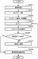
次に、図17を参照しつつ、本開示の第1の実施の形態に係るロボット1における画像認識処理について説明する。図17は、本開示の第1の実施の形態に係るロボット1における画像認識処理を示すフローチャートである。ここでは、ロボット1がクラウドサーバ3に画像認識処理を依頼してから、画像認識結果を受信するまでの期間、ロボット1が回転し、ロボット1処理中であることを表現する処理をする。 Next, the image recognition process in the
まず、ユーザはロボット1に発話する(S1701)。例えば、ユーザは、図14で説明したように人形1402をロボット1に差し出し、「これ何?」といった発話を行う。 First, the user speaks to the robot 1 (S1701). For example, as described with reference to FIG. 14, the user presents the
次に、ロボット1の音声認識処理部204は、発話への回答に画像認識処理が必要か否かを判断する(S1703)。ここで、メモリ206には、回答に画像認識処理が必要な発話の特徴量を示す1以上の発話参照データが事前に記憶されている。したがって、音声認識処理部204は、ユーザが発話した音声の特徴量とメモリ206に記憶されたいずれかの発話参照データとの類似度が閾値以上であれば、画像認識処理が必要と判断すればよい。 Next, the voice
例えば、画像認識処理が必要な発話としては、上述した「これ何?」といった認識対象物を問い合わせる発話や「画像認識処理を実行」といったコマンド形式の発話が採用できる。また、ユーザが人差し指と中指との2本の指を立てて、「これいくつ?」というような数の問い合わせに応えるために、「これいくつ?」が画像認識処理が必要な発話として採用されてもよい。 For example, as an utterance that requires image recognition processing, an utterance that inquires about a recognition object such as “What is this?” Or a command-style utterance that “executes image recognition processing” can be employed. In addition, in order for the user to raise two fingers, the index finger and the middle finger, to answer a number of inquiries such as “how many?”, “How many?” Is adopted as an utterance that requires image recognition processing. Also good.
S1703において、回答に画像認識処理の必要があると判定された場合(S1703でYES)、処理はS1704に進められ、回答に画像認識処理の必要がないと判定された場合(S1703でNO)、処理はS1708に進められる。 If it is determined in S1703 that the answer requires image recognition processing (YES in S1703), the process proceeds to S1704, and if it is determined that the answer does not require image recognition processing (NO in S1703), The process proceeds to S1708.
次に、カメラ108は、認識対象物を含む1枚の画像を撮影する(S1702,S1704)。ここで、音声認識処理部204は、主制御部201に画像認識処理が必要である旨の通知を行い、この通知を受けた主制御部201は、顔認識処理部203に撮影コマンドを送信することで、カメラ108に認識対象物を撮影させればよい。 Next, the
なお、主制御部201は、音声認識処理部204により画像認識処理が必要であると判断された場合、音声情報出力制御部202に「知りたい物をロボットの正面に向けて下さい。」といったメッセージを通知し、スピーカ216からそのメッセージを出力させてもよい。これにより、ロボット1は、ユーザに対して認識対象物をロボット1の正面に差し出させることができ、カメラ108の撮影範囲に認識対象物が含まれない事態を回避できる。 When the voice
次に、主制御部201は、S1704で撮影した画像がクラウドサーバ3に対して画像認識処理を要求する必要があるか否かを判定する(S1705)。画像認識処理の要求をする必要があると主制御部201が判定した場合(S1705でYES)、通信部210は、S1704で撮影した画像をクラウドサーバ3に送信する(S1706)。一方、画像認識処理を要求する必要がないと主制御部201が判定した場合(S1705でNO)、処理はS1708に進められる。 Next, the
ここで、メモリ206には、画像認識処理の要求が不必要な参照画像の特徴量である認識不要参照データが事前に記憶されている。したがって、主制御部201は、S1704で撮影した画像の特徴量と認識不要参照データとの類似度が閾値以上であれば、画像認識処理の要求が不必要であると判定し、S1704で撮影した画像の特徴量と認識不要参照データとの類似度が閾値未満であれば、画像認識処理の要求が必要と判定すればよい。 Here, the
参照画像としては、例えば、ユーザの顔画像が含まれる。ユーザの顔画像としては、例えば、ロボット1を主に取り扱う子供の顔画像や、その子供の家族の顔画像が含まれていてもよい。これは、ユーザの顔を認識するというような頻度の高い処理に、いちいちクラウドサーバ3に画像認識処理の要求をしてしまうと、ユーザの待ち時間が大きくなり、ユーザのストレスが過大になる点を考慮したものである。また、参照画像としては、ユーザが1本、2本というように1本以上の指を立てた画像が採用されてもよい。 Examples of the reference image include a user's face image. As the user's face image, for example, a face image of a child who mainly handles the
次に、ロボット1は、画像認識結果が得られるまで、進捗表現処理を行う(S1707)。進捗表現処理の詳細については後ほど説明する。 Next, the
クラウドサーバ3に画像認識処理の要求が必要である場合、画像認識結果が得られるまでに所定時間以上かかってしまう。この場合、ロボット1が何も動作を行わなければ、ユーザはロボット1が故障したのではないかと判断する虞がある。そこで、本態様では、クラウドサーバ3に画像認識処理の要求が必要である場合、後述する進捗表現処理(S1707)を行う。 When the
次に、クラウドサーバ3は、画像認識処理を行う(S1709)。画像認識処理の詳細については後ほど説明する。 Next, the
画像認識結果が得られると、ロボット1は進捗表現処理を終了する。 When the image recognition result is obtained, the
次に、音声情報出力制御部202は、画像認識結果をスピーカ216から出力し、発話により画像認識結果の回答を行う(S1708)。この場合、音声情報出力制御部202は、例えば認識対象物の名称を示す音声をスピーカ216から出力する。例えば、図14に示すように人形1402が認識されたとすると、スピーカ216から「人形」の音声が出力される。 Next, the voice information
尚、S1703でNO、S1705でNOと判定された場合のS1708の処理は例えば下記のようになる。発話への回答に画像認識処理が必要でないと判定された場合として(S1703でNO)、例えば、ロボット1とユーザとが対話をするようなケースが該当したとする。この場合、S1708では、音声情報出力制御部202は、ユーザとの対話に応答する音声をスピーカ216から出力すればよい。 For example, the processing in S1708 when NO is determined in S1703 and NO is determined in S1705 is as follows. As a case where it is determined that an image recognition process is not necessary for replying to an utterance (NO in S1703), for example, a case where the
また、S1704で撮影した画像がクラウドサーバ3に対して画像認識処理を要求する必要がない場合として(S1705でNO)、ユーザの名前をロボット1に問い合わせたり、ユーザが指を立てて「これいくつ?」というような問い合わせを行うケースが該当したとする。この場合、S1708では、音声情報出力制御部202は、ユーザの名前や「2本です。」というような音声をスピーカ216から出力すればよい。 Further, assuming that the image taken in S1704 does not need to request the
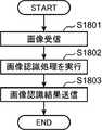
図18は、本開示の第1の実施の形態において、図17のS1709に示す画像認識処理の詳細を示すフローチャートである。まず、通信部301は、ロボット1から送信された画像を受信する(S1801)。 FIG. 18 is a flowchart showing details of the image recognition process shown in S1709 of FIG. 17 in the first embodiment of the present disclosure. First, the
次に、処理部302は、画像認識処理を実行する(S1802)。例えば、図14に示すユースケースでは、人形1402を含む画像が画像認識処理の対象となる。処理部302は、例えば、機械学習により得られた、物体の画像の特徴量と物体の名称とが対応付けて登録された物体モデルデータベースを備えている。処理部302は、ロボット1から送信された画像から特徴量を抽出し、抽出した特徴量と物体モデルデータベースに登録された各物体の特徴量とを照合し、類似度が最も高い物体を認識対象物と判定すればよい。図14の例では、「人形」が画像認識結果となる。 Next, the
次に、通信部301は、処理部302による画像認識結果をロボット1に送信する(S1803)。 Next, the
図19は、本開示の第1の実施の形態において、図17のS1707に示す進捗表現処理の詳細を示すフローチャートである。 FIG. 19 is a flowchart showing details of the progress expression process shown in S1707 of FIG. 17 in the first embodiment of the present disclosure.
まず、主制御部201は、第1回転速度V1と、第1回転速度V1よりも遅い第2回転速度V2と、現在の回転速度を設定するための変数である回転速度Vとを準備する(S1901)。S1901では、回転速度Vはデフォルト値として0が設定される。 First, the
ここで、第1回転速度V1は、ロボット1が処理中であることをユーザに伝えるときのロボット1の回転速度である。第2回転速度V2は、ユーザの位置を検出するためにカメラ108が周囲環境を連続撮影するときのロボット1の回転速度である。第2回転速度V2が過大であれば、周囲環境の画像がぶれてしまい、ユーザをうまく検知できない可能性がある。一方、第2回転速度V2が過小であれば、ユーザの位置を検出する時間が過大となり、ユーザにストレスを与えてしまう。そこで、第2回転速度V2としては、周囲環境を正確に撮影できる速度が採用できる。ここでは、第2回転速度V2は第1回転速度V1よりも低いとしたが、高くてもよい。 Here, the first rotation speed V1 is the rotation speed of the
次に、主制御部201は、回転速度Vを第1回転速度V1に設定する(S1902)。 Next, the
次に、筐体駆動輪制御部214は、主制御部201から回転速度Vを第1回転速度V1に設定するコマンドを受け付け、ロボット1を第1回転速度V1で回転させる(S1903)。詳細には、筐体駆動輪制御部214は、筐体駆動輪212を構成する第1駆動輪110と第2駆動輪111とが、それぞれ、第1回転速度V1で逆方向に回転するように第1モータ112と第2モータ113とを駆動すればよい。 Next, the housing drive
次に、主制御部201は、通信部210が画像認識結果を受信していなければ(S1904でNO)、処理をS1903に戻し、S1903〜S1904の処理を行う。これにより、画像認識結果が受信されるまで、ロボット1は回転動作を繰り返し、ユーザに画像認識処理中であることを伝えることができる。 Next, if the
一方、通信部210が画像認識結果を受信すると(S1904でYES)、主制御部201は、回転速度Vを第2回転速度V2に設定する(S1905)。 On the other hand, when the
次に、筐体駆動輪制御部214は、主制御部201から回転速度Vを第2回転速度V2に設定するコマンドを受け付け、ロボット1を第2回転速度V2で回転させる(S1906)。詳細には、筐体駆動輪制御部214は、筐体駆動輪212を構成する第1駆動輪110と第2駆動輪111とが、それぞれ、第2回転速度V2で逆方向に回転するように第1モータ112と第2モータ113とを駆動すればよい。これにより、ユーザの位置を検出するためのロボット1の回転動作が行われる。 Next, the housing drive
次に、顔認識処理部203は、主制御部201から連続撮影を実行するための撮影コマンドを受け付け、カメラ108に周囲環境の画像を連続撮影させる(S1907)。 Next, the face
次に、顔認識処理部203は、ユーザの顔を認識できたのであれば(S1908でYES)、そのことを主制御部201に通知し、カメラ108の連続撮影を停止させる(S1909)。一方、顔認識処理部203は、ユーザの顔を認識できていなければ(S1908でNO)、処理をS1906に戻す。以上により、ユーザの顔が認識できるまで、ロボット1は回転しながら、周囲環境の画像を撮影することになる。 Next, if the face
ここで、顔認識処理部203は、メモリ206に記憶されたユーザの顔の画像の特徴量に対する類似度が閾値以上である物体を含む、周囲環境の画像を検出できたとき、その周囲環境の画像にユーザが存在すると判定すればよい。そして、顔認識処理部203は、検出した周囲環境の画像内におけるユーザの顔の位置及びサイズから、現実空間でのユーザの位置を検出すればよい。ここで、検出されるユーザの位置は、例えば、該当する周囲環境の画像を撮影した時点でのロボット1の基準方向及びユーザの位置のなす角度と、ロボット1からユーザの位置までの距離とによって特定されればよい。基準方向としては、ロボット1の進行方向(ロボット1の正面に直行する方向)が採用できる。更に、顔認識処理部203は、該当する周囲環境の画像に含まれるユーザの顔の形状等からユーザの顔の方位を検出してもよい。 Here, when the face
尚、メモリ206に複数のユーザの顔の画像の特徴量が記憶されており、且つ、ロボット1の周囲にメモリ206に特徴量が記憶された複数のユーザが含まれていれば、認識対象物を差し出したユーザとは別のユーザの位置が検出される可能性がある。 If the feature values of the images of the faces of a plurality of users are stored in the
これを防止するために、顔認識処理部203は画像認識処理の開始時時に認識対象物を差し出したユーザの顔を撮影してユーザの顔の特徴量を抽出し、メモリ206に記憶させておく。そして、顔認識処理部203は、メモリ206に記憶された特徴量との類似度が閾値以上の物体を含む周囲環境の画像を検出できたとき、その周囲環境の画像にユーザが存在すると判定してもよい。例えば、図17のS1704において、顔認識処理部203は認識対象物を差し出したユーザの顔が含まれるように認識対象物の画像を撮影し、得られた画像からユーザの顔の特徴量を抽出してメモリ206に記憶させておけばよい。 In order to prevent this, the face
S1910では、筐体駆動輪制御部214は、主制御部201からロボット1の回転を停止させるコマンドを受け付け、第1モータ112と第2モータ113との駆動を停止させることで、ロボット1の回転を停止させる。 In S1910, the housing driving
S1911では、筐体駆動輪制御部214は、主制御部201からロボット1を、S1908で検出したユーザの位置付近まで移動させるコマンドを取得し、その位置付近までロボット1が移動するように、第1駆動輪110と第2駆動輪111とを駆動させる。このとき、主制御部201は、ロボット1の表示部211が、ユーザの正面と対面するように筐体駆動輪制御部214にコマンドを出力すればよい。 In S1911, the casing drive
詳細には、主制御部201は、まず、該当するユーザの位置付近までロボット1を移動させるコマンドを筐体駆動輪制御部214に出力する。そして、該当するユーザの位置付近までロボットが移動すると、主制御部201は、S1908で検出されたユーザの顔の方位が、表示部211と直行するように、ロボット1を回転させるコマンドを筐体駆動輪制御部214に出力すればよい。 Specifically, the
このように本態様によれば、ユーザの問いに応答するために所定時間以上を要する場合、第1駆動輪110と第2駆動輪111とをそれぞれ逆方向に回転させて球体状の筐体101を回転させて、ロボット1を回転させる。これにより、球体状のロボット1の形状を利用して、ユーザとの対話中にロボット1の回転によりロボット1が処理中であることをユーザに伝えることができる。 As described above, according to this aspect, when a predetermined time or more is required to respond to the user's question, the
また、本態様によると、ロボット1の正面をユーザに向けて画像認識処理の結果をユーザに出力する。そのため、ロボット1の正面がユーザに向けられていない状態で、画像認識処理の結果を出力する不都合を防止できる。 Further, according to this aspect, the result of the image recognition process is output to the user with the front of the
(第2の実施の形態)
第2の実施の形態は、画像認識処理の進捗状況が進むにつれて、ロボット1の回転速度を減速させることを特徴とする。なお、第2の実施の形態において第1の実施の形態と同一構成のものは同一の符号を付し、説明を省く。(Second Embodiment)
The second embodiment is characterized in that the rotation speed of the
第2の実施の形態では、全体的な処理は、図17と同じであるが、S1709とS1707とが相違する。 In the second embodiment, the overall processing is the same as in FIG. 17, but S1709 and S1707 are different.
図20は、本開示の第2の実施の形態において、図17のS1709に示す画像認識処理の詳細を示すフローチャートである。S2001、S2008は図18のS1801、S1803と同じであるため、説明を省く。 FIG. 20 is a flowchart showing details of the image recognition process shown in S1709 of FIG. 17 in the second embodiment of the present disclosure. S2001 and S2008 are the same as S1801 and S1803 in FIG.
S2002では、処理部302は、画像認識処理に要するステージ数Mを規定するパラメータを準備する。ここで、ステージ数Mはクラウドサーバ3が採用する画像認識処理の内容に応じて事前に定められた値が採用される。例えば、クラウドサーバ3が3つのステージ数からなる画像認識処理を採用するのであれば、M=3が設定される。 In step S2002, the
S2003では、処理部302は、ステージ番号Nを初期値「0」に設定する。ここで、ステージ番号Nは処理中のステージを特定するための番号である。 In S2003, the
S2004では、処理部302は、ステージ番号Nを1インクリメントする。 In S2004, the
S2005では、処理部302は、ステージ番号Nの画像認識処理を実行する。 In step S2005, the
S2006では、処理部302は、ステージ番号Nがステージ数Mに到達したか否かを判定する。ステージ番号Nがステージ数Mに到達していれば(S2006でYES)、処理部302は、画像認識結果が得られたので、処理をS2008に進める。 In S2006, the
ステージ番号Nがステージ数Mに到達していなければ(S2006でNO)、処理部302は、通信部210を用いて、画像認識結果の一部が完了した旨の通知をロボット1に行う(S2007)。このとき、処理部302は、処理が終了したステージ番号Nとステージ数Mとをロボット1に送信する。 If the stage number N has not reached the stage number M (NO in S2006), the
S2007の処理が終了すると、処理はS2004に戻される。これにより、次のステージ番号Nの画像認識処理が実行される。 When the process of S2007 ends, the process returns to S2004. Thereby, the image recognition process of the next stage number N is performed.
次に、画像認識処理のステージについて説明する。図21は、ロボット1の回転速度と画像認識処理のステージ番号Nが示すステージ「N」との関係を示す図である。図21の例では、画像認識処理はステージ番号N=1,2,3で示される3つのステージ「1」,「2」,「3」で構成される。 Next, the stage of image recognition processing will be described. FIG. 21 is a diagram illustrating a relationship between the rotation speed of the
ステージ「1」は認識対象物の色を認識するステージであり、ステージ「2」は認識対象物のブランドを認識するステージであり、ステージ「3」は認識対象物が最終的に何であるかを認識するステージである。 Stage “1” is a stage for recognizing the color of the recognition object, stage “2” is a stage for recognizing the brand of the recognition object, and stage “3” is what the recognition object is finally. It is a stage to recognize.
例えば、認識対象物が市販の清涼飲料水であるとすると、ステージ「1」では、清涼飲料水を構成する色が認識される。例えば、水の清涼飲料水であれば、認識結果は「透明」となる。処理部302は、例えば、ロボット1から送信された画像から認識対象物を抽出し、抽出した認識対象物の色を解析する処理を行うことで、認識対象物の色を認識すればよい。認識対象物が複数の色で構成される場合もある。この場合、処理部302は、一定の割合以上を占める上位数色の色を認識結果としてもよい。 For example, if the recognition target is a commercially available soft drink, the color constituting the soft drink is recognized at stage “1”. For example, for a soft drink of water, the recognition result is “transparent”. For example, the
ステージ「2」では、処理部302は、例えば、清涼飲料水のボトルのラベルに記載された文字を認識することで、ブランド名を認識する。清涼飲料水のボトルのラベルに商品名「XXX」と記載されていれば、認識結果は、例えば、「XXX」となる。 In stage “2”, the
ステージ「3」では、処理部302は、例えば、上述の物体モデルデータベースを用いて、認識対象物が最終的に何であるかを認識する。例えば、清涼飲料水が認識されたのであれば、認識結果は「清涼飲料水」となる。ここで、清涼飲料水の種類まで認識できたのであれば、認識結果は、例えば、「清涼飲料水:水」となる。 In stage “3”, the
図22は、本開示の第2の実施の形態において、図17のS1707に示す進捗表現処理の詳細を示すフローチャートである。 FIG. 22 is a flowchart showing details of the progress expression process shown in S1707 of FIG. 17 in the second embodiment of the present disclosure.
図22において、S2101、S2102、S2103、S2104、S2107、S2108、S2109、S2110、S2111、S2112、S2113は、図19のS1901、S1902、S1903、S1904、S1905、S1906、S1907、S1908、S1909、S1910、S1911と同じであるので、説明を省く。 22, S2101, S2102, S2103, S2104, S2107, S2108, S2109, S2110, S2111, S2112, and S2113 are S1901, S1902, S1903, S1904, S1905, S1906, S1907, S1908, S1909, S1910, and S1910, respectively. Since this is the same as S1911, the description is omitted.
S2105は、図20のS2007において、クラウドサーバ3が送信した画像認識処理の一部が完了した旨の通知をロボット1が受信する処理である。主制御部201は、画像認識処理の一部が完了した旨の通知を通信部210がクラウドサーバ3から受信していなければ(S2105でNO)、処理をS2103に戻す。一方、主制御部201は、画像認識処理の一部が完了した旨の通知を通信部210がクラウドサーバ3から受信していれば(S2105でYES)、処理をS2106に進める。S2105では、ロボット1は、処理が終了したステージ番号Nとステージ数Mとを受信する。 S2105 is a process in which the
S2106では、主制御部201は、S2105で受信した処理が終了したステージ番号Nとステージ数Mとを用いて、回転速度VをV=V1×(1−N/M)に設定し、回転速度Vを減速させる。例えば、ステージ「1」が終了すると、S2105にて、ロボット1はN=1を受信するので、ステージ「2」の処理中では、回転速度Vは、V=V1×(1−1/M)に設定される。 In step S2106, the
これにより、主制御部201は、画像認識処理のステージが1段階進む毎に回転速度Vを1段階低く設定する。 Thus, the
図21の例では、ステージ「1」の処理中においては、主制御部201は、回転速度VをV1に設定する。これにより、第1駆動輪110、第2駆動輪111は、回転速度V1で互いに逆方向に回転され、ロボット1は回転速度V1で回転する。 In the example of FIG. 21, during the process of stage “1”, the
ステージ「1」の処理が終了すると、主制御部201は、回転速度VをV=V1×2/3に設定する。これにより、ステージ「2」の処理中においては、第1駆動輪110、第2駆動輪111は、回転速度V1×2/3で互いに逆方向に回転し、ロボット1は回転速度V1×2/3で回転する。 When the process of stage “1” is completed, the
ステージ「2」の処理が終了すると、主制御部201は、回転速度VをV=V1×1/3に設定する。これにより、ステージ「3」の処理中においては、第1駆動輪110、第2駆動輪111は、回転速度V1×1/3で互いに逆方向に回転し、ロボット1は回転速度V1×1/3で回転する。 When the process of stage “2” ends, the
このように、本態様によれば、画像認識処理のステージが進むにつれて、カウンターウェイト114の振幅が減少されるので、ロボット1の動作を通じて、画像認識処理の進捗状況をユーザに通知できる。 As described above, according to this aspect, the amplitude of the
図22のS2104で、ステージ「M」の画像認識処理の結果が受信されると(S2104でYES)、処理はS2107に進められる。S2107以降の処理は図19のS1905以降の処理と同じである。ここで、S2107で設定される回転速度V2は、画像認識処理の最終のステージ「M」でのロボット1の回転速度よりも遅い値が採用されればよい。これにより、最終のステージ「M」の終了後にロボット1の回転速度Vが増大し、ユーザに違和感を与えることを防止できる。 When the result of the image recognition process of stage “M” is received in S2104 of FIG. 22 (YES in S2104), the process proceeds to S2107. The processing after S2107 is the same as the processing after S1905 in FIG. Here, the rotation speed V2 set in S2107 may be a value slower than the rotation speed of the
このように、第2の実施の形態によれば、画像認識処理のステージが進むにつれて、ロボット1の回転速度が減速されるので、ロボット1の動作を通じて、画像認識処理の進捗状況をユーザに通知できる。 As described above, according to the second embodiment, as the stage of the image recognition process progresses, the rotation speed of the
(変形例1)
実施の形態1、2では、画像認識処理をクラウドサーバ3に要求する場合に、ロボット1を回転させた。本開示はこれに限定されず、画像認識処理以外の処理(例えば、音声認識処理)をクラウドサーバ3に要求する場合に、ロボット1を回転させてもよい。画像認識処理以外の処理であっても、クラウドサーバ3に処理を要求した場合、処理結果が得られるまでに所定時間以上要することもある。この場合、処理結果が得られるまでにロボット1を回転させることで、ロボット1が故障したとユーザが判断することを防止できる。(Modification 1)
In the first and second embodiments, the
(変形例2)
実施の形態1、2では、表示部211を備えていたが、これは一例であり、表示部211は省かれても良い。表示部211はロボットの顔の一部を表示するので、表示部211が有る方が、ロボット1が処理中であることをうまく表現できる。しかし、表示部211が無くても、処理結果が得られるまでロボット1を回転させれば、ロボット1が処理中であることを十分にユーザに伝えることができる。(Modification 2)
In the first and second embodiments, the
(変形例3)
第2の実施の形態では、画像認識処理のステージが進むにつれて、V1×「N/M」ずつ回転速度Vが減速されたが、これは一例であり、ステージが進むにつれて回転速度Vの減速量が大きくなる或いは小さくなるように回転速度Vは減速されてもよい。(Modification 3)
In the second embodiment, the rotational speed V is decelerated by V1 × “N / M” as the stage of the image recognition process progresses. This is an example, and the amount of deceleration of the rotational speed V as the stage progresses. The rotational speed V may be decelerated so that becomes larger or smaller.
(変形例4)
第1、第2の実施の形態では、画像認識処理の終了後、カメラ108を用いてユーザを発見したが、本開示はこれに限定されない。例えば、ユーザが画像認識処理を要求する発話を行ったとき、音声認識処理部204は、その発話の音声をマイク217を用いて取得し、取得した音声の方向及び強度からユーザの位置を特定し、メモリ206に記憶する。そして、画像認識処理の終了時に、主制御部201は、メモリ206に記憶されたユーザの位置にロボット1を移動させるコマンドを、筐体駆動輪制御部214に出力すればよい。ここで、画像認識処理を要求する発話を行ってから画像認識処理が終了するまでの間にユーザが別の場所に移動することもある。この場合、音声認識処理部204は、画像認識処理を要求する発話の音声を取得したときに、音声の特徴量を抽出し、メモリ206に記憶する。そして、音声認識処理部204は、画像認識処理が終了するまで、メモリ206に記憶した特徴量を用いて、該当するユーザが発話する音声をモニタし、ユーザの位置を追跡してもよい。(Modification 4)
In the first and second embodiments, the user is discovered using the
(本開示の実施の形態の概要)
本開示の一態様に係るロボットは、
球体状の筐体と、
前記筐体の内側部に配置されたフレームと、
前記フレームに備え付けられた入力装置と、
前記フレームに備え付けられた出力装置と、
前記フレームに備え付けられ、外部ネットワークに接続される通信回路と、
前記フレームに備え付けられ、前記筐体の内周面に接して前記筐体を回転させる一組の駆動輪と、
前記入力装置を介して入力したユーザの入力指示に対して、所定時間以上を要する所定の処理に基づいて応答する場合、前記一組の駆動輪をそれぞれ逆方向に回転させて前記球体状の筐体を回転させ、
前記出力装置を介して前記所定の処理に基づく応答を出力させるとき、前記一組の駆動輪による前進方向を前記ユーザに向けて前記球体状の筐体の回転を停止させる制御回路と、を備えたものである。(Outline of Embodiment of the Present Disclosure)
A robot according to an aspect of the present disclosure is provided.
A spherical housing;
A frame disposed on the inner side of the housing;
An input device provided in the frame;
An output device provided in the frame;
A communication circuit provided in the frame and connected to an external network;
A set of drive wheels provided on the frame and rotating the housing in contact with an inner peripheral surface of the housing;
When responding to a user input instruction input via the input device based on a predetermined process that requires a predetermined time or more, the pair of driving wheels are rotated in the opposite directions, respectively, so that the spherical housing is Rotate the body,
A control circuit for stopping the rotation of the spherical casing with the forward direction of the set of driving wheels directed to the user when outputting a response based on the predetermined process via the output device. It is a thing.
本態様によると、前記入力装置を介して入力したユーザの入力指示に対して、所定時間以上を要する所定の処理に基づいて応答する場合、前記一組の駆動輪をそれぞれ逆方向に回転させて前記球体状の筐体を回転させる。これにより、前記球体状のロボットの形状を利用して、前記ユーザとの対話中に前記筐体の回転により前記ロボットが処理中であることを前記ユーザに伝えることができる。 According to this aspect, when responding to a user input instruction input via the input device based on a predetermined process that requires a predetermined time or more, the pair of driving wheels are respectively rotated in the opposite directions. The spherical housing is rotated. Thus, the shape of the spherical robot can be used to inform the user that the robot is processing by rotating the housing during the dialogue with the user.
また、前記所定の処理に基づく応答を受信した場合、単に前記球体状の筐体の回転を停止させるだけであると、前記ロボットの前進方向が正面であるとすると、前記ロボットが正面を前記ユーザに向けていない状態で前記ロボットが停止することがある。 Further, when the response based on the predetermined process is received, if the rotation of the spherical housing is merely stopped, and the forward direction of the robot is the front, the robot faces the front The robot may stop in a state where the robot is not directed to.
本態様によると、前記出力装置を介して前記所定の処理に基づく応答を出力させるとき、前記一組の駆動輪による前進方向を前記ユーザに向けて前記球体状の筐体の回転を停止させる。これにより、前記所定の処理の結果に基づく応答を前記ユーザに向けて出力させることができる。そのため、前記ロボットの正面が前記ユーザに向けられていない状態で、前記所定の処理の結果に基づく応答を出力する不都合を防止できる。 According to this aspect, when outputting the response based on the predetermined process via the output device, the rotation of the spherical casing is stopped with the forward direction of the set of driving wheels directed toward the user. Thereby, the response based on the result of the predetermined process can be output to the user. Therefore, it is possible to prevent the inconvenience of outputting a response based on the result of the predetermined process in a state where the front of the robot is not directed toward the user.
また、上記態様において、例えば、
撮像方向が前記前進方向に向くように、前記フレームに備え付けられたカメラを更に備えてもよい。In the above aspect, for example,
You may further provide the camera with which the said flame | frame was equipped so that an imaging direction might face the said advance direction.
この場合、前記カメラは、前記ロボットの顔の一部、例えば、口、又は鼻を構成する。これにより、前記出力装置を介して前記所定の処理に基づく応答を出力させるとき、前記カメラを前記ユーザに向けて前記球体状の筐体の回転を停止させる。これにより、前記所定の処理の結果に基づく応答を前記ユーザに向けて出力させることができる。そのため、前記ロボットの顔が前記ユーザに向けられていない状態で、前記所定の処理の結果に基づく応答を出力する不都合を防止できる。 In this case, the camera constitutes a part of the face of the robot, for example, the mouth or the nose. Accordingly, when outputting a response based on the predetermined process via the output device, the rotation of the spherical casing is stopped with the camera facing the user. Thereby, the response based on the result of the predetermined process can be output to the user. Therefore, it is possible to prevent the inconvenience of outputting a response based on the result of the predetermined process in a state where the face of the robot is not directed to the user.
また、上記態様において、例えば、
前記制御回路は、
前記球体状の筐体が回転している間、前記カメラを用いた撮像を行い、
前記出力装置を介して前記所定の処理の結果に基づく応答を出力するまでに、前記カメラによって撮像された画像に基づき前記ユーザの位置を認識し、前記認識されたユーザの位置に前記表示部を向けた状態で前記球体状の筐体の回転を停止させてもよい。In the above aspect, for example,
The control circuit includes:
While the spherical housing is rotating, perform imaging using the camera,
Until the response based on the result of the predetermined processing is output via the output device, the position of the user is recognized based on the image captured by the camera, and the display unit is placed at the recognized position of the user. The rotation of the spherical housing may be stopped in the state of being directed.
本態様によれば、カメラによって撮像された画像に基づきユーザの位置が認識されているので、ユーザの位置を正確に認識できる。 According to this aspect, since the position of the user is recognized based on the image captured by the camera, the position of the user can be accurately recognized.
また、上記態様において、例えば、
前記前進方向に向かうように前記フレームに備え付けられ、少なくとも前記ロボットの顔の一部を表示する表示部を更に備えてもよい。In the above aspect, for example,
You may further provide the display part which is provided in the said flame | frame so that it may go to the said advance direction, and displays at least one part of the said robot's face.
この場合、前記表示部に表示される前記ロボットの顔の一部は、例えば、口、又は鼻を構成する。これにより、前記出力装置を介して前記所定の処理に基づく応答を出力させるとき、前記少なくとも顔の一部を表示する表示部を前記ユーザに向けて前記球体状の筐体の回転を停止させる。これにより、前記所定の処理の結果に基づく応答を前記ユーザに向けて出力させることができる。そのため、前記ロボットの顔が前記ユーザに向けられていない状態で、前記所定の処理の結果に基づく応答を出力する不都合を防止できる。 In this case, a part of the face of the robot displayed on the display unit forms, for example, a mouth or a nose. Accordingly, when outputting a response based on the predetermined process via the output device, the rotation of the spherical casing is stopped with the display unit displaying at least a part of the face facing the user. Thereby, the response based on the result of the predetermined process can be output to the user. Therefore, it is possible to prevent the inconvenience of outputting a response based on the result of the predetermined process in a state where the face of the robot is not directed to the user.
また、上記態様において、例えば、
前記制御回路は、
前記球体状の筐体の回転を停止させた後、前記認識されたユーザの位置に前記表示部を向けた状態で、前記出力装置を介して前記所定の処理の結果に基づく応答を出力させてもよい。In the above aspect, for example,
The control circuit includes:
After stopping the rotation of the spherical casing, a response based on the result of the predetermined process is output via the output device with the display unit facing the recognized user position. Also good.
本態様によれば、筐体の回転停止後にユーザの位置に表示部が向けられて、所定の処理の結果に基づく応答が出力されることになる。 According to this aspect, the display unit is directed to the position of the user after the rotation of the casing is stopped, and a response based on the result of the predetermined process is output.
また、上記態様において、例えば、
前記所定の処理は、2以上の工程からなり、
前記制御回路は、
前記2以上の工程の各々が終わる毎に、前記一組の駆動輪の回転速度を制御して前記球体状の筐体を回転させる速度を減速させてもよい。In the above aspect, for example,
The predetermined process includes two or more steps.
The control circuit includes:
Each time the two or more steps are finished, the rotational speed of the pair of drive wheels may be controlled to reduce the speed of rotating the spherical housing.
本態様によれば、前記所定の処理の工程が進むにつれて、前記一組の駆動輪の回転速度が減少されるので、ロボットの動作を通じて、所定の処理の進捗状況をユーザに通知できる。 According to this aspect, as the predetermined processing step proceeds, the rotational speed of the set of driving wheels is reduced, so that the progress of the predetermined processing can be notified to the user through the operation of the robot.
また、上記態様において、例えば、
前記所定の処理は、前記外部ネットワークを介して接続された外部サーバにおける画像認識処理であってもよい。In the above aspect, for example,
The predetermined process may be an image recognition process in an external server connected via the external network.
画像認識処理は処理負荷が過大なので、外部サーバで実行されることが多い。この場合、処理結果が得られるまで、所定時間以上かかってしまう。本態様では、所定の処理が外部サーバで実行される場合であっても、処理結果が得られるまで、ロボットは、回転する動作を行う。そのため、ユーザに対して内部処理が実行中であることを伝えることができる。 Image recognition processing is often executed by an external server because the processing load is excessive. In this case, it takes a predetermined time or more until a processing result is obtained. In this aspect, even when a predetermined process is executed by an external server, the robot performs a rotating operation until a process result is obtained. Therefore, it is possible to inform the user that internal processing is being executed.
また、上記態様において、例えば、
前記制御回路は、前記画像認識処理において、
前記カメラを用いて認識対象物を撮像させ、
前記通信回路を用いて前記外部ネットワークを経由して前記撮像された認識対象物の画像を前記外部サーバに送信させ、
前記通信回路を用いて前記外部サーバから前記認識対象物の画像の認識結果を受信させ、
前記出力装置を介して前記受信した認識結果を出力させてもよい。In the above aspect, for example,
The control circuit, in the image recognition process,
Image a recognition object using the camera,
Sending the image of the captured recognition object to the external server via the external network using the communication circuit,
Receiving the recognition result of the image of the recognition object from the external server using the communication circuit;
The received recognition result may be output via the output device.
本態様によれば、処理負荷が過大な画像認識処理が外部サーバで実行されるので、ロボットは認識対象物の撮像と、認識結果を外部サーバからの受信とを行えばよく、ロボットの処理負荷を軽減できる。 According to this aspect, since the image recognition processing with an excessive processing load is executed by the external server, the robot only has to perform imaging of the recognition target and reception of the recognition result from the external server. Can be reduced.
また、上記態様において、例えば、
前記入力装置は、マイクであり、
前記入力装置を介して入力したユーザの入力指示は音声の指示であってもよい。In the above aspect, for example,
The input device is a microphone;
The user's input instruction input via the input device may be a voice instruction.
本態様によれば、ユーザは、手入力で入力指示を入力しなくとも、入力指示の音声を発話するだけで、ロボットに所定の処理を指示できる。そのため、入力指示を入力する際のユーザの負担が軽減される。特に、幼児のように、手入力が困難なユーザにとってこの態様は有用となる。 According to this aspect, even if the user does not input an input instruction manually, the user can instruct the robot to perform predetermined processing only by speaking the voice of the input instruction. Therefore, the burden on the user when inputting the input instruction is reduced. In particular, this aspect is useful for a user who has difficulty in manual input such as an infant.
また、上記態様において、例えば、
前記出力装置は、スピーカであってもよい。In the above aspect, for example,
The output device may be a speaker.
本態様では、スピーカを通じて処理結果が出力されるので、ユーザはロボットに注視しなくても処理結果を知ることができる。 In this aspect, since the processing result is output through the speaker, the user can know the processing result without paying attention to the robot.
本開示の別の一態様に係るロボットは、
球体状の筐体と、
前記筐体の内側部に配置されたフレームと、
前記フレームに備え付けられた、少なくともロボットの顔の一部を表示する表示部と、
前記フレームに備え付けられた入力装置と、
前記フレームに備え付けられた出力装置と、
前記フレームに備え付けられ、外部ネットワークに接続される通信回路と、
前記フレームに備え付けられ、前記筐体の内周面に接して前記筐体を回転させる一組の駆動輪と、
前記入力装置を介して入力したユーザの入力指示に対して、所定時間以上を要する所定の処理に基づいて応答する場合、前記一組の駆動輪をそれぞれ逆方向に回転させて前記球体状の筐体を回転させ、
前記出力装置を介して前記所定の処理に基づく応答を出力させるとき、前記ユーザに対して前記表示部を向けて前記球体状の筐体の回転を停止させる制御回路と、を備えたものである。A robot according to another aspect of the present disclosure is provided.
A spherical housing;
A frame disposed on the inner side of the housing;
A display unit provided on the frame for displaying at least a part of the face of the robot;
An input device provided in the frame;
An output device provided in the frame;
A communication circuit provided in the frame and connected to an external network;
A set of drive wheels provided on the frame and rotating the housing in contact with an inner peripheral surface of the housing;
When responding to a user input instruction input via the input device based on a predetermined process that requires a predetermined time or more, the pair of driving wheels are rotated in the opposite directions, respectively, so that the spherical housing is Rotate the body,
And a control circuit that stops the rotation of the spherical casing with the display unit facing the user when outputting a response based on the predetermined process via the output device. .
本態様によると、前記入力装置を介して入力したユーザの入力指示に対して、所定時間以上を要する所定の処理に基づいて応答する場合、前記一組の駆動輪をそれぞれ逆方向に回転させて前記球体状の筐体を回転させる。これにより、前記球体状のロボットの形状を利用して、前記ユーザとの対話中に前記筐体の回転により前記ロボットが処理中であることを前記ユーザに伝えることができる。 According to this aspect, when responding to a user input instruction input via the input device based on a predetermined process that requires a predetermined time or more, the pair of driving wheels are respectively rotated in the opposite directions. The spherical housing is rotated. Thus, the shape of the spherical robot can be used to inform the user that the robot is processing by rotating the housing during the dialogue with the user.
また、前記表示部は、前記ロボットの顔の一部、例えば、口、又は鼻を構成する。前記所定の処理に基づく応答を受信した場合、単に前記球体状の筐体の回転を停止させるだけであると、前記ロボットの顔が前記ユーザの向いていない状態で前記ロボットが停止することがある。 The display unit constitutes a part of the robot's face, for example, a mouth or a nose. When a response based on the predetermined process is received, the robot may stop with the robot face not facing the user simply by stopping the rotation of the spherical casing. .
本態様によると、前記出力装置を介して前記所定の処理に基づく応答を出力させるとき、前記ユーザに対して前記表示部を向けて前記球体状の筐体の回転を停止させる。これにより、前記所定の処理の結果に基づく応答を前記ユーザに向けて出力させることができる。そのため、前記ロボットの顔が前記ユーザの向けられていない状態で、前記所定の処理の結果に基づく応答を出力する不都合を防止できる。 According to this aspect, when outputting a response based on the predetermined process via the output device, the display unit is directed toward the user to stop the rotation of the spherical casing. Thereby, the response based on the result of the predetermined process can be output to the user. Therefore, it is possible to prevent the inconvenience of outputting a response based on the result of the predetermined process in a state where the face of the robot is not directed to the user.
上記態様において、例えば、
前記フレームに備え付けられたカメラを更に備え、
前記制御回路は、
前記球体状の筐体が回転している間、前記カメラを用いた撮像を行い、
前記出力装置を介して前記所定の処理の結果に基づく応答を出力するまでに、前記カメラによって撮像された画像に基づき前記ユーザの位置を認識し、前記認識されたユーザの位置に前記表示部を向けた状態で前記球体状の筐体の回転を停止させてもよい。In the above embodiment, for example,
Further comprising a camera attached to the frame;
The control circuit includes:
While the spherical housing is rotating, perform imaging using the camera,
Until the response based on the result of the predetermined processing is output via the output device, the position of the user is recognized based on the image captured by the camera, and the display unit is placed at the recognized position of the user. The rotation of the spherical housing may be stopped in the state of being directed.
本態様によれば、カメラによって撮像された画像に基づきユーザの位置が認識されているので、ユーザの位置を正確に認識できる。 According to this aspect, since the position of the user is recognized based on the image captured by the camera, the position of the user can be accurately recognized.
上記態様において、例えば、
前記制御回路は、
前記球体状の筐体の回転を停止させた後、前記認識されたユーザの位置に前記表示部を向けた状態で、前記出力装置を介して前記所定の処理の結果に基づく応答を出力させてもよい。In the above embodiment, for example,
The control circuit includes:
After stopping the rotation of the spherical casing, a response based on the result of the predetermined process is output via the output device with the display unit facing the recognized user position. Also good.
本態様によれば、筐体の回転停止後にユーザの位置に表示部が向けられて、所定の処理の結果に基づく応答が出力されることになる。 According to this aspect, the display unit is directed to the position of the user after the rotation of the casing is stopped, and a response based on the result of the predetermined process is output.
上記態様において、例えば、
前記所定の処理は、2以上の工程からなり、
前記制御回路は、
前記2以上の工程の各々が終わる毎に、前記一組の駆動輪の回転速度を制御して前記球体状の筐体を回転させる速度を減速させてもよい。In the above embodiment, for example,
The predetermined process includes two or more steps.
The control circuit includes:
Each time the two or more steps are finished, the rotational speed of the pair of drive wheels may be controlled to reduce the speed of rotating the spherical housing.
本態様によれば、前記所定の処理の工程が進むにつれて、前記一組の駆動輪の回転速度が減少されるので、ロボットの動作を通じて、所定の処理の進捗状況をユーザに通知できる。 According to this aspect, as the predetermined processing step proceeds, the rotational speed of the set of driving wheels is reduced, so that the progress of the predetermined processing can be notified to the user through the operation of the robot.
上記態様において、例えば、
前記フレームに備え付けられたカメラを設け、
前記所定の処理は、前記外部ネットワークを介して接続された外部サーバにおける画像認識処理であってもよい。In the above embodiment, for example,
A camera provided on the frame;
The predetermined process may be an image recognition process in an external server connected via the external network.
画像認識処理は処理負荷が過大なので、外部サーバで実行されることが多い。この場合、処理結果が得られるまで、所定時間以上かかってしまう。本態様では、所定の処理が外部サーバで実行される場合であっても、処理結果が得られるまで、ロボットは、回転する動作を行う。そのため、ユーザに対して内部処理が実行中であることを伝えることができる。 Image recognition processing is often executed by an external server because the processing load is excessive. In this case, it takes a predetermined time or more until a processing result is obtained. In this aspect, even when a predetermined process is executed by an external server, the robot performs a rotating operation until a process result is obtained. Therefore, it is possible to inform the user that internal processing is being executed.
上記態様において、例えば、
前記制御回路は、前記画像認識処理において、
前記カメラを用いて認識対象物を撮像させ、
前記通信回路を用いて前記外部ネットワークを経由して前記撮像された認識対象物の画像を前記外部サーバに送信させ、
前記通信回路を用いて前記外部サーバから前記認識対象物の画像の認識結果を受信させ、
前記出力装置を介して前記受信した認識結果を出力させてもよい。In the above embodiment, for example,
The control circuit, in the image recognition process,
Image a recognition object using the camera,
Sending the image of the captured recognition object to the external server via the external network using the communication circuit,
Receiving the recognition result of the image of the recognition object from the external server using the communication circuit;
The received recognition result may be output via the output device.
本態様によれば、処理負荷が過大な画像認識処理が外部サーバで実行されるので、ロボットは認識対象物の撮像と、認識結果を外部サーバからの受信とを行えばよく、ロボットの処理負荷を軽減できる。 According to this aspect, since the image recognition processing with an excessive processing load is executed by the external server, the robot only has to perform imaging of the recognition target and reception of the recognition result from the external server. Can be reduced.
本開示の更に別の一態様に係るロボットは、
球体状の筐体と、
前記筐体の内側部に配置されたフレームと、
前記フレームに備え付けられた、少なくともロボットの顔の一部を表示する表示部と、
前記フレームに備え付けられたカメラと、
前記フレームに備え付けられた入力装置と、
前記フレームに備え付けられた出力装置と、
前記フレームに備え付けられ、外部ネットワークに接続される通信回路と、
前記フレームに備え付けられ、前記筐体の内周面に接して前記筐体を回転させる一組の駆動輪と、
前記入力装置を介して入力したユーザの音声指示が画像認識を必要とすると判断した場合に前記カメラを用いて認識対象物を撮像させ、前記外部ネットワークを経由して前記撮像された認識対象物の画像を外部サーバに送信させ、前記外部サーバから前記認識対象物の画像の認識結果を受信させ、前記出力装置を介して前記受信した認識結果を出力させる制御回路と、を備え、
前記制御回路は、
前記外部サーバによる前記認識対象物の画像の認識結果が必要な場合、前記一組の駆動輪をそれぞれ逆方向に回転させて前記球体状の筐体を回転させ、
前記外部サーバから前記認識対象物の画像の認識結果を受信すると、前記ユーザに対して前記表示部を向けて前記球体状の筐体の回転を停止させる、ものである。A robot according to still another aspect of the present disclosure is provided.
A spherical housing;
A frame disposed on the inner side of the housing;
A display unit provided on the frame for displaying at least a part of the face of the robot;
A camera mounted on the frame;
An input device provided in the frame;
An output device provided in the frame;
A communication circuit provided in the frame and connected to an external network;
A set of drive wheels provided on the frame and rotating the housing in contact with an inner peripheral surface of the housing;
When it is determined that the user's voice instruction input via the input device requires image recognition, the recognition object is imaged using the camera, and the captured recognition object is detected via the external network. A control circuit that transmits an image to an external server, receives an image recognition result of the recognition target object from the external server, and outputs the received recognition result via the output device;
The control circuit includes:
When the recognition result of the image of the recognition target by the external server is required, the pair of driving wheels are rotated in the opposite directions to rotate the spherical housing,
When the recognition result of the image of the recognition target is received from the external server, the rotation of the spherical casing is stopped with the display unit facing the user.
本態様によると、前記ロボットが前記ユーザの問いに応答するために前記外部サーバによる前記認識対象物の画像の認識結果が必要な場合、前記一組の駆動輪をそれぞれ逆方向に回転させて前記球体状の筐体を回転させる。これにより、前記画像認識が必要な場合、前記球体状のロボットの形状を利用して、前記ユーザとの対話中に前記筐体の回転により前記ロボットが処理中であることを前記ユーザに伝える。 According to this aspect, when the recognition result of the image of the recognition target by the external server is necessary for the robot to respond to the user's question, the pair of driving wheels are rotated in the opposite directions, respectively. Rotate the spherical housing. Accordingly, when the image recognition is necessary, the shape of the spherical robot is used to inform the user that the robot is processing by rotating the housing during the dialogue with the user.
また、前記表示部は、前記ロボットの顔の一部、例えば、口、又は鼻を構成する。前記認識結果を受信した場合、単に前記球体状の筐体の回転を停止させるだけであると、前記ロボットの顔が前記ユーザの向いていない状態で前記ロボットが停止することがある。 The display unit constitutes a part of the robot's face, for example, a mouth or a nose. When the recognition result is received, if the rotation of the spherical housing is simply stopped, the robot may stop with the face of the robot not facing the user.
本態様によると、前記外部サーバから前記認識対象物の画像の認識結果を受信すると、前記ユーザに対して前記表示部を向けて前記球体状の筐体の回転を停止させる。これにより、前記認識結果を前記ユーザに向けて出力させることができる。そのため、前記ロボットの顔が前記ユーザの向けられていない状態で、前記認識結果を出力する不都合を防止できる。 According to this aspect, when the recognition result of the image of the recognition target is received from the external server, the rotation of the spherical housing is stopped with the display unit facing the user. Thereby, the recognition result can be output to the user. Therefore, it is possible to prevent the inconvenience of outputting the recognition result in a state where the robot face is not directed to the user.
上記態様において、例えば、
前記制御回路は、
前記球体状の筐体が回転している間、前記カメラを用いた撮像を行い、
前記スピーカを介して前記認識結果に基づく応答を出力するまでに、前記カメラによって撮像された画像に基づき前記ユーザの位置を認識し、前記認識されたユーザの位置に前記表示部を向けた状態で前記球体状の筐体の回転を停止させてもよい。In the above embodiment, for example,
The control circuit includes:
While the spherical housing is rotating, perform imaging using the camera,
Until the response based on the recognition result is output via the speaker, the user's position is recognized based on the image captured by the camera, and the display unit is directed to the recognized user's position. The rotation of the spherical housing may be stopped.
本態様によれば、カメラによって撮像された画像に基づきユーザの位置が認識されているので、ユーザの位置を正確に認識できる。 According to this aspect, since the position of the user is recognized based on the image captured by the camera, the position of the user can be accurately recognized.
上記態様において、例えば、
画像認識用の参照データを格納するメモリを設け、
前記制御回路は、
前記ユーザの音声指示に対して応答するために前記外部サーバによる前記認識対象物の画像の認識結果は必要でなく、前記メモリに格納された前記画像認識用の参照データに基づく前記認識対象物の画像認識で前記応答が可能であると判断した場合、前記一組の駆動輪の回転により前記球体状の筐体を回転させる制御を行うことなく、前記スピーカを介して前記参照データに基づく認識結果を出力させてもよい。In the above embodiment, for example,
A memory for storing reference data for image recognition is provided.
The control circuit includes:
In order to respond to the user's voice instruction, the recognition result of the image of the recognition object by the external server is not required, and the recognition object based on the reference data for image recognition stored in the memory is not necessary. If it is determined that the response is possible by image recognition, the recognition result based on the reference data via the speaker without performing control to rotate the spherical housing by rotation of the pair of drive wheels May be output.
例えば、ユーザの顔認識などは、前記ロボットの内部にメモリを設けて、前記メモリに格納された画像認識用の参照データを用いて行うことが可能である。 For example, a user's face recognition or the like can be performed using a reference data for image recognition stored in the memory by providing a memory inside the robot.
ユーザが前記ロボットに対して、例えば、「私は誰?」と問う場合、前記外部サーバによる前記認識対象物の画像の認識結果は必要でなく、前記ロボットの内部にメモリに格納された画像認識用の参照データを参照すれば足りる。また、ユーザが人差し指と中指との2本の指を立てて「これいくつ?」と、前記ユーザが前記ロボットに対して問う場合も、前記クラウドサーバによる前記認識対象物の画像の認識結果は必要でなく、前記ロボットの内部にメモリに格納された画像認識用の参照データを参照すれば足りる。このような場合、前記ユーザを待たせることはほんどない。 When the user asks the robot, for example, “Who am I?”, The recognition result of the image of the recognition object by the external server is not necessary, and the image recognition stored in the memory inside the robot is not necessary. It is sufficient to refer to the reference data. In addition, when the user asks the robot, “How many?” With two fingers of the index finger and middle finger, the recognition result of the image of the recognition object by the cloud server is necessary. Instead, it is sufficient to refer to reference data for image recognition stored in a memory inside the robot. In such a case, the user is hardly allowed to wait.
そのため、このような場合には、前記一組の駆動輪の回転により前記球体状の筐体を回転させる制御を行うことなく、前記スピーカを介して前記参照データに基づく認識結果を出力させるようにした。 Therefore, in such a case, the recognition result based on the reference data is output via the speaker without performing control to rotate the spherical casing by rotating the pair of driving wheels. did.
上記態様において、例えば、
前記制御回路は、
前記球体状の筐体の回転を停止させた後、前記認識されたユーザの位置に前記表示部を向けた状態で、前記出力装置を介して前記所定の処理の結果に基づく応答を出力させてもよい。In the above embodiment, for example,
The control circuit includes:
After stopping the rotation of the spherical casing, a response based on the result of the predetermined process is output via the output device with the display unit facing the recognized user position. Also good.
本態様によれば、筐体の回転停止後にユーザの位置に表示部が向けられて、所定の処理の結果に基づく応答が出力されることになる。 According to this aspect, the display unit is directed to the position of the user after the rotation of the casing is stopped, and a response based on the result of the predetermined process is output.
上記態様において、例えば、
前記画像認識は、2以上の工程からなり、
前記制御回路は、
前記2以上の工程の各々が終わる毎に、前記一組の駆動輪の回転速度を制御して前記球体状の筐体を回転させる速度を減速させてもよい。In the above embodiment, for example,
The image recognition consists of two or more steps,
The control circuit includes:
Each time the two or more steps are finished, the rotational speed of the pair of drive wheels may be controlled to reduce the speed of rotating the spherical housing.
本態様によれば、前記所定の処理の工程が進むにつれて、前記一組の駆動輪の回転速度が減少されるので、ロボットの動作を通じて、所定の処理の進捗状況をユーザに通知できる。 According to this aspect, as the predetermined processing step proceeds, the rotational speed of the set of driving wheels is reduced, so that the progress of the predetermined processing can be notified to the user through the operation of the robot.
本開示の例示的な実施の形態にかかるロボットによれば、内部処理の進行状況をユーザに伝えるために有用である。 The robot according to the exemplary embodiment of the present disclosure is useful for informing the user of the progress of internal processing.
M ステージ数
N ステージ番号
1 ロボット
3 クラウドサーバ
4 携帯端末
9 制御回路
101 筐体
102 フレーム
103 第1回転板
104 第2回転板
105 第1表示部
106 第2表示部
107 第3表示部
108 カメラ
109 制御回路
110 第1駆動輪
111 第2駆動輪
112 第1モータ
113 第2モータ
114 カウンターウェイト
115 ガイドシャフト
116 スイングアーム
117 回転用モータ
118 回転シャフト
119 ベルト
120 モータプーリ
201 主制御部
202 音声情報出力制御部
203 顔認識処理部
204 音声認識処理部
205 表示情報出力制御部
206 メモリ
210 通信部
211 表示部
212 筐体駆動輪
213 シャフト制御部
214 筐体駆動輪制御部
215 重り駆動機構制御部
216 スピーカ
217 マイク
218 重り駆動機構
301 通信部
302 処理部
1500 ロボットシステム
M number of stages
Claims (21)
Translated fromJapanese前記筐体の内側部に配置されたフレームと、
前記フレームに備え付けられた入力装置と、
前記フレームに備え付けられた出力装置と、
前記フレームに備え付けられ、外部ネットワークに接続される通信回路と、
前記フレームに備え付けられ、前記筐体の内周面に接して前記筐体を回転させる一組の駆動輪と、
前記入力装置を介して入力したユーザの入力指示に対して、所定時間以上を要する所定の処理に基づいて応答する場合、前記一組の駆動輪をそれぞれ逆方向に回転させて前記球体状の筐体を回転させ、
前記出力装置を介して前記所定の処理に基づく応答を出力させるとき、前記一組の駆動輪による前進方向を前記ユーザに向けて前記球体状の筐体の回転を停止させる制御回路と、を備えた
ロボット。A spherical housing;
A frame disposed on the inner side of the housing;
An input device provided in the frame;
An output device provided in the frame;
A communication circuit provided in the frame and connected to an external network;
A set of drive wheels provided on the frame and rotating the housing in contact with an inner peripheral surface of the housing;
When responding to a user input instruction input via the input device based on a predetermined process that requires a predetermined time or more, the pair of driving wheels are rotated in the opposite directions, respectively, so that the spherical housing is Rotate the body,
A control circuit for stopping the rotation of the spherical casing with the forward direction of the set of driving wheels directed to the user when outputting a response based on the predetermined process via the output device. Robot.
請求項1記載のロボット。The camera further includes a camera attached to the frame such that the imaging direction is in the forward direction.
The robot according to claim 1.
前記球体状の筐体が回転している間、前記カメラを用いた撮像を行い、
前記出力装置を介して前記所定の処理の結果に基づく応答を出力するまでに、前記カメラによって撮像された画像に基づき前記ユーザの位置を認識し、前記認識されたユーザの位置に前記表示部を向けた状態で前記球体状の筐体の回転を停止させる、
請求項2記載のロボット。The control circuit includes:
While the spherical housing is rotating, perform imaging using the camera,
Until the response based on the result of the predetermined processing is output via the output device, the position of the user is recognized based on the image captured by the camera, and the display unit is placed at the recognized position of the user. Stop the rotation of the spherical casing in a state of being directed,
The robot according to claim 2.
請求項3記載のロボット。A display unit that is provided on the frame so as to be directed in the forward direction, and displays at least a part of the face of the robot;
The robot according to claim 3.
前記球体状の筐体の回転を停止させた後、前記認識されたユーザの位置に前記表示部を向けた状態で、前記出力装置を介して前記所定の処理の結果に基づく応答を出力させる、
請求項4記載のロボット。The control circuit includes:
After stopping the rotation of the spherical housing, the response based on the result of the predetermined process is output via the output device with the display unit facing the recognized user position.
The robot according to claim 4.
前記制御回路は、
前記2以上の工程の各々が終わる毎に、前記一組の駆動輪の回転速度を制御して前記球体状の筐体を回転させる速度を減速させる、
請求項1記載のロボット。The predetermined process includes two or more steps.
The control circuit includes:
Each time the two or more steps are finished, the rotational speed of the set of driving wheels is controlled to reduce the rotational speed of the spherical housing.
The robot according to claim 1.
請求項2記載のロボット。The predetermined process is an image recognition process in an external server connected via the external network.
The robot according to claim 2.
前記カメラを用いて認識対象物を撮像させ、
前記通信回路を用いて前記外部ネットワークを経由して前記撮像された認識対象物の画像を前記外部サーバに送信させ、
前記通信回路を用いて前記外部サーバから前記認識対象物の画像の認識結果を受信させ、
前記出力装置を介して前記受信した認識結果を出力させる、
請求項7記載のロボット。The control circuit, in the image recognition process,
Image a recognition object using the camera,
Sending the image of the captured recognition object to the external server via the external network using the communication circuit,
Receiving the recognition result of the image of the recognition object from the external server using the communication circuit;
Outputting the received recognition result via the output device;
The robot according to claim 7.
前記入力装置を介して入力したユーザの入力指示は音声の指示である、
請求項1から8のいずれか1項に記載のロボット。The input device is a microphone;
The user's input instruction input via the input device is a voice instruction.
The robot according to any one of claims 1 to 8.
請求項9記載のロボット。The output device is a speaker;
The robot according to claim 9.
前記筐体の内側部に配置されたフレームと、
前記フレームに備え付けられた、少なくともロボットの顔の一部を表示する表示部と、
前記フレームに備え付けられた入力装置と、
前記フレームに備え付けられた出力装置と、
前記フレームに備え付けられ、外部ネットワークに接続される通信回路と、
前記フレームに備え付けられ、前記筐体の内周面に接して前記筐体を回転させる一組の駆動輪と、
前記入力装置を介して入力したユーザの入力指示に対して、所定時間以上を要する所定の処理に基づいて応答する場合、前記一組の駆動輪をそれぞれ逆方向に回転させて前記球体状の筐体を回転させ、
前記出力装置を介して前記所定の処理に基づく応答を出力させるとき、前記ユーザに対して前記表示部を向けて前記球体状の筐体の回転を停止させる制御回路と、を備えた
ロボット。A spherical housing;
A frame disposed on the inner side of the housing;
A display unit provided on the frame for displaying at least a part of the face of the robot;
An input device provided in the frame;
An output device provided in the frame;
A communication circuit provided in the frame and connected to an external network;
A set of drive wheels provided on the frame and rotating the housing in contact with an inner peripheral surface of the housing;
When responding to a user input instruction input via the input device based on a predetermined process that requires a predetermined time or more, the pair of driving wheels are rotated in the opposite directions, respectively, so that the spherical housing is Rotate the body,
And a control circuit that stops the rotation of the spherical casing with the display unit facing the user when outputting a response based on the predetermined process via the output device.
前記制御回路は、
前記球体状の筐体が回転している間、前記カメラを用いた撮像を行い、
前記出力装置を介して前記所定の処理の結果に基づく応答を出力するまでに、前記カメラによって撮像された画像に基づき前記ユーザの位置を認識し、前記認識されたユーザの位置に前記表示部を向けた状態で前記球体状の筐体の回転を停止させる、
請求項11記載のロボット。Further comprising a camera attached to the frame;
The control circuit includes:
While the spherical housing is rotating, perform imaging using the camera,
Until the response based on the result of the predetermined processing is output via the output device, the position of the user is recognized based on the image captured by the camera, and the display unit is placed at the recognized position of the user. Stop the rotation of the spherical casing in a state of being directed,
The robot according to claim 11.
前記球体状の筐体の回転を停止させた後、前記認識されたユーザの位置に前記表示部を向けた状態で、前記出力装置を介して前記所定の処理の結果に基づく応答を出力させる、
請求項11又は12のいずれか1項に記載のロボット。The control circuit includes:
After stopping the rotation of the spherical housing, the response based on the result of the predetermined process is output via the output device with the display unit facing the recognized user position.
The robot according to claim 11 or 12.
前記制御回路は、
前記2以上の工程の各々が終わる毎に、前記一組の駆動輪の回転速度を制御して前記球体状の筐体を回転させる速度を減速させる、
請求項11記載のロボット。The predetermined process includes two or more steps.
The control circuit includes:
Each time the two or more steps are finished, the rotational speed of the set of driving wheels is controlled to reduce the rotational speed of the spherical housing.
The robot according to claim 11.
前記所定の処理は、前記外部ネットワークを介して接続された外部サーバにおける画像認識処理である、
請求項11記載のロボット。A camera provided on the frame;
The predetermined process is an image recognition process in an external server connected via the external network.
The robot according to claim 11.
前記カメラを用いて認識対象物を撮像させ、
前記通信回路を用いて前記外部ネットワークを経由して前記撮像された認識対象物の画像を前記外部サーバに送信させ、
前記通信回路を用いて前記外部サーバから前記認識対象物の画像の認識結果を受信させ、
前記出力装置を介して前記受信した認識結果を出力させる、
請求項15記載のロボット。The control circuit, in the image recognition process,
Image a recognition object using the camera,
Sending the image of the captured recognition object to the external server via the external network using the communication circuit,
Receiving the recognition result of the image of the recognition object from the external server using the communication circuit;
Outputting the received recognition result via the output device;
The robot according to claim 15.
前記筐体の内側部に配置されたフレームと、
前記フレームに備え付けられた、少なくともロボットの顔の一部を表示する表示部と、
前記フレームに備え付けられたカメラと、
前記フレームに備え付けられた入力装置と、
前記フレームに備え付けられた出力装置と、
前記フレームに備え付けられ、外部ネットワークに接続される通信回路と、
前記フレームに備え付けられ、前記筐体の内周面に接して前記筐体を回転させる一組の駆動輪と、
前記入力装置を介して入力したユーザの音声指示が画像認識を必要とすると判断した場合に前記カメラを用いて認識対象物を撮像させ、前記外部ネットワークを経由して前記撮像された認識対象物の画像を外部サーバに送信させ、前記外部サーバから前記認識対象物の画像の認識結果を受信させ、前記出力装置を介して前記受信した認識結果を出力させる制御回路と、を備え、
前記制御回路は、
前記外部サーバによる前記認識対象物の画像の認識結果が必要な場合、前記一組の駆動輪をそれぞれ逆方向に回転させて前記球体状の筐体を回転させ、
前記外部サーバから前記認識対象物の画像の認識結果を受信すると、前記ユーザに対して前記表示部を向けて前記球体状の筐体の回転を停止させる、
ロボット。A spherical housing;
A frame disposed on the inner side of the housing;
A display unit provided on the frame for displaying at least a part of the face of the robot;
A camera mounted on the frame;
An input device provided in the frame;
An output device provided in the frame;
A communication circuit provided in the frame and connected to an external network;
A set of drive wheels provided on the frame and rotating the housing in contact with an inner peripheral surface of the housing;
When it is determined that the user's voice instruction input via the input device requires image recognition, the recognition object is imaged using the camera, and the captured recognition object is detected via the external network. A control circuit that transmits an image to an external server, receives an image recognition result of the recognition target object from the external server, and outputs the received recognition result via the output device;
The control circuit includes:
When the recognition result of the image of the recognition target by the external server is required, the pair of driving wheels are rotated in the opposite directions to rotate the spherical housing,
When receiving the recognition result of the image of the recognition object from the external server, the rotation of the spherical housing is stopped with the display unit facing the user.
robot.
前記球体状の筐体が回転している間、前記カメラを用いた撮像を行い、
前記スピーカを介して前記認識結果に基づく応答を出力するまでに、前記カメラによって撮像された画像に基づき前記ユーザの位置を認識し、前記認識されたユーザの位置に前記表示部を向けた状態で前記球体状の筐体の回転を停止させる、
請求項17記載のロボット。The control circuit includes:
While the spherical housing is rotating, perform imaging using the camera,
Until the response based on the recognition result is output via the speaker, the user's position is recognized based on the image captured by the camera, and the display unit is directed to the recognized user's position. Stopping the rotation of the spherical housing,
The robot according to claim 17.
前記制御回路は、
前記ユーザの音声指示に対して応答するために前記外部サーバによる前記認識対象物の画像の認識結果は必要でなく、前記メモリに格納された前記画像認識用の参照データに基づく前記認識対象物の画像認識で前記応答が可能であると判断した場合、前記一組の駆動輪の回転により前記球体状の筐体を回転させる制御を行うことなく、前記スピーカを介して前記参照データに基づく認識結果を出力させる、
請求項17記載のロボット。A memory for storing reference data for image recognition is provided.
The control circuit includes:
In order to respond to the user's voice instruction, the recognition result of the image of the recognition object by the external server is not required, and the recognition object based on the reference data for image recognition stored in the memory is not necessary. If it is determined that the response is possible by image recognition, the recognition result based on the reference data via the speaker without performing control to rotate the spherical housing by rotation of the pair of drive wheels Output
The robot according to claim 17.
前記球体状の筐体の回転を停止させた後、前記認識されたユーザの位置に前記表示部を向けた状態で、前記出力装置を介して前記所定の処理の結果に基づく応答を出力させる、
請求項17から19のいずれか1項に記載のロボット。The control circuit includes:
After stopping the rotation of the spherical housing, the response based on the result of the predetermined process is output via the output device with the display unit facing the recognized user position.
The robot according to any one of claims 17 to 19.
前記制御回路は、
前記2以上の工程の各々が終わる毎に、前記一組の駆動輪の回転速度を制御して前記球体状の筐体を回転させる速度を減速させる、
請求項17から19のいずれか1項に記載のロボット。The image recognition consists of two or more steps,
The control circuit includes:
Each time the two or more steps are finished, the rotational speed of the set of driving wheels is controlled to reduce the rotational speed of the spherical housing.
The robot according to any one of claims 17 to 19.
Priority Applications (6)
| Application Number | Priority Date | Filing Date | Title |
|---|---|---|---|
| JP2016100222AJP2017205324A (en) | 2016-05-19 | 2016-05-19 | robot |
| EP17799207.0AEP3459607A4 (en) | 2016-05-19 | 2017-05-09 | Robot |
| CA2995671ACA2995671A1 (en) | 2016-05-19 | 2017-05-09 | Robot |
| PCT/JP2017/017438WO2017199782A1 (en) | 2016-05-19 | 2017-05-09 | Robot |
| CN201780001183.0ACN107847807A (en) | 2016-05-19 | 2017-05-09 | robot |
| US15/888,171US20180154513A1 (en) | 2016-05-19 | 2018-02-05 | Robot |
Applications Claiming Priority (1)
| Application Number | Priority Date | Filing Date | Title |
|---|---|---|---|
| JP2016100222AJP2017205324A (en) | 2016-05-19 | 2016-05-19 | robot |
Publications (1)
| Publication Number | Publication Date |
|---|---|
| JP2017205324Atrue JP2017205324A (en) | 2017-11-24 |
Family
ID=60325061
Family Applications (1)
| Application Number | Title | Priority Date | Filing Date |
|---|---|---|---|
| JP2016100222AWithdrawnJP2017205324A (en) | 2016-05-19 | 2016-05-19 | robot |
Country Status (6)
| Country | Link |
|---|---|
| US (1) | US20180154513A1 (en) |
| EP (1) | EP3459607A4 (en) |
| JP (1) | JP2017205324A (en) |
| CN (1) | CN107847807A (en) |
| CA (1) | CA2995671A1 (en) |
| WO (1) | WO2017199782A1 (en) |
Cited By (1)
| Publication number | Priority date | Publication date | Assignee | Title |
|---|---|---|---|---|
| JP2019197471A (en)* | 2018-05-11 | 2019-11-14 | トヨタ自動車株式会社 | Autonomous mobile system, autonomous mobile body, charging doc, control method, and program |
Families Citing this family (10)
| Publication number | Priority date | Publication date | Assignee | Title |
|---|---|---|---|---|
| JP2017205313A (en)* | 2016-05-19 | 2017-11-24 | パナソニックIpマネジメント株式会社 | robot |
| USD903559S1 (en) | 2017-03-16 | 2020-12-01 | Nio Nextev Limited | Voice assistant |
| AU2019284212B2 (en)* | 2018-06-12 | 2023-11-30 | The Trailer Buddy Pty Ltd | A vehicle camera telemetry system |
| CN108594669A (en)* | 2018-06-15 | 2018-09-28 | 河池学院 | A kind of smart home robot control system |
| JP7495125B2 (en)* | 2018-12-03 | 2024-06-04 | Groove X株式会社 | ROBOT, SPEECH SYNTHESIS PROGRAM, AND SPEECH OUTPUT METHOD |
| KR20210057582A (en)* | 2019-11-12 | 2021-05-21 | 삼성전자주식회사 | Mistakenly sucked object identifying robot cleaner and controlling method thereof |
| CN111127998A (en)* | 2020-01-07 | 2020-05-08 | 北京小米移动软件有限公司 | Intelligent globe, control method of intelligent globe and storage medium |
| IT202000007240A1 (en)* | 2020-04-06 | 2021-10-06 | Aixcellence Srl | Device for maintaining the trajectory of a vehicle |
| DE102020127019B4 (en) | 2020-10-14 | 2022-06-09 | Deutsches Zentrum für Luft- und Raumfahrt e.V. | Spherical Robot |
| EP4115779B1 (en)* | 2021-07-06 | 2025-09-03 | Vorwerk & Co. Interholding GmbH | Household appliance with multifunctional display |
Family Cites Families (31)
| Publication number | Priority date | Publication date | Assignee | Title |
|---|---|---|---|---|
| JP2000274509A (en)* | 1999-03-26 | 2000-10-03 | Recruit Co Ltd | Spherical driving device |
| CA2274770A1 (en)* | 1999-06-15 | 2000-12-15 | Serge Caron | Robot ball |
| US20100131078A1 (en)* | 1999-10-27 | 2010-05-27 | Brown David W | Event driven motion systems |
| KR20020061961A (en)* | 2001-01-19 | 2002-07-25 | 사성동 | Intelligent pet robot |
| JP2004148439A (en)* | 2002-10-30 | 2004-05-27 | Sony Corp | Spherical robot and spherical robot control method |
| SE0402672D0 (en)* | 2004-11-02 | 2004-11-02 | Viktor Kaznov | Ball robot |
| EP2050544B1 (en)* | 2005-09-30 | 2011-08-31 | iRobot Corporation | Robot system with wireless communication by TCP/IP transmissions |
| JP5751610B2 (en)* | 2010-09-30 | 2015-07-22 | 学校法人早稲田大学 | Conversation robot |
| US10281915B2 (en)* | 2011-01-05 | 2019-05-07 | Sphero, Inc. | Multi-purposed self-propelled device |
| US9218316B2 (en)* | 2011-01-05 | 2015-12-22 | Sphero, Inc. | Remotely controlling a self-propelled device in a virtualized environment |
| US9090214B2 (en)* | 2011-01-05 | 2015-07-28 | Orbotix, Inc. | Magnetically coupled accessory for a self-propelled device |
| US9836046B2 (en)* | 2011-01-05 | 2017-12-05 | Adam Wilson | System and method for controlling a self-propelled device using a dynamically configurable instruction library |
| US9429940B2 (en)* | 2011-01-05 | 2016-08-30 | Sphero, Inc. | Self propelled device with magnetic coupling |
| US20120244969A1 (en)* | 2011-03-25 | 2012-09-27 | May Patents Ltd. | System and Method for a Motion Sensing Device |
| US8894465B2 (en)* | 2011-04-28 | 2014-11-25 | Kids Ii, Inc. | Eccentric motion toy |
| US8672062B2 (en)* | 2011-05-26 | 2014-03-18 | Gregory C Schroll | Internal means for rotating an object between gravitationally stable states |
| US9259842B2 (en)* | 2011-06-10 | 2016-02-16 | Microsoft Technology Licensing, Llc | Interactive robot initialization |
| JP5172049B2 (en)* | 2011-06-14 | 2013-03-27 | パナソニック株式会社 | Robot apparatus, robot control method, and robot control program |
| US20130095725A1 (en)* | 2011-10-06 | 2013-04-18 | Paul J. von Mohr | Figurine toy in combination with a portable, removable wireless computer device having a visual display screen |
| CN202438152U (en)* | 2012-01-09 | 2012-09-19 | 南宁卓蓝电子科技有限公司 | Antiphonal singing dancing robot |
| US9428019B1 (en)* | 2013-07-09 | 2016-08-30 | Guardbot Inc. | Drive and stabilizaton system for amphibious robotic ball |
| FR3011375B1 (en)* | 2013-10-01 | 2017-01-27 | Aldebaran Robotics | METHOD FOR DIALOGUE BETWEEN A MACHINE, SUCH AS A HUMANOID ROBOT, AND A HUMAN INTERLOCUTOR, COMPUTER PROGRAM PRODUCT AND HUMANOID ROBOT FOR IMPLEMENTING SUCH A METHOD |
| US20150317511A1 (en)* | 2013-11-07 | 2015-11-05 | Orbeus, Inc. | System, method and apparatus for performing facial recognition |
| US9829882B2 (en)* | 2013-12-20 | 2017-11-28 | Sphero, Inc. | Self-propelled device with center of mass drive system |
| JP2015138147A (en)* | 2014-01-22 | 2015-07-30 | シャープ株式会社 | Server, interactive device, interactive system, interactive method and interactive program |
| CA2949822A1 (en)* | 2014-05-23 | 2015-11-26 | Sphero, Inc. | Causing gesture responses on connected devices |
| JPWO2016068262A1 (en)* | 2014-10-29 | 2017-08-10 | 京セラ株式会社 | Communication robot |
| US9390847B1 (en)* | 2015-02-19 | 2016-07-12 | The United States Of America As Represented By The Secretary Of The Navy | System and method for electromagnetic-based propulsion |
| CN105459126A (en)* | 2015-12-30 | 2016-04-06 | 深圳亿家智宝电子科技有限公司 | Robot communication device and achieving method thereof |
| US20170189824A1 (en)* | 2016-01-04 | 2017-07-06 | Sphero, Inc. | Modular sensing device utilized with autonomous self-propelled device |
| US20180089699A1 (en)* | 2016-09-23 | 2018-03-29 | Sphero, Inc. | Systems and methods for managing a user experience for consumer products |
- 2016
- 2016-05-19JPJP2016100222Apatent/JP2017205324A/ennot_activeWithdrawn
- 2017
- 2017-05-09CACA2995671Apatent/CA2995671A1/ennot_activeAbandoned
- 2017-05-09CNCN201780001183.0Apatent/CN107847807A/enactivePending
- 2017-05-09WOPCT/JP2017/017438patent/WO2017199782A1/ennot_activeCeased
- 2017-05-09EPEP17799207.0Apatent/EP3459607A4/ennot_activeWithdrawn
- 2018
- 2018-02-05USUS15/888,171patent/US20180154513A1/ennot_activeAbandoned
Cited By (2)
| Publication number | Priority date | Publication date | Assignee | Title |
|---|---|---|---|---|
| JP2019197471A (en)* | 2018-05-11 | 2019-11-14 | トヨタ自動車株式会社 | Autonomous mobile system, autonomous mobile body, charging doc, control method, and program |
| JP7052546B2 (en) | 2018-05-11 | 2022-04-12 | トヨタ自動車株式会社 | Autonomous mobile systems, autonomous mobiles, charging docks, control methods, and programs |
Also Published As
| Publication number | Publication date |
|---|---|
| US20180154513A1 (en) | 2018-06-07 |
| EP3459607A1 (en) | 2019-03-27 |
| EP3459607A4 (en) | 2019-05-08 |
| CA2995671A1 (en) | 2017-11-23 |
| WO2017199782A1 (en) | 2017-11-23 |
| CN107847807A (en) | 2018-03-27 |
Similar Documents
| Publication | Publication Date | Title |
|---|---|---|
| CN107847806B (en) | Robot | |
| WO2017199782A1 (en) | Robot | |
| WO2017199783A1 (en) | Robot | |
| JP7747032B2 (en) | Information processing device and information processing method | |
| US10799806B2 (en) | Robot | |
| JP2011000681A (en) | Communication robot | |
| CN111736585B (en) | Robot and robot control method | |
| CN113056315B (en) | Information processing device, information processing method, and program | |
| CN113168835B (en) | Information processing device, information processing method and program | |
| JP2025044986A (en) | system | |
| JP2025048057A (en) | system | |
| JP2025052387A (en) | system | |
| JP2025052311A (en) | system | |
| JP2024154394A (en) | Electronics | |
| JP2025056352A (en) | system | |
| JP2025055231A (en) | system | |
| JP2025055244A (en) | system | |
| JP2025055452A (en) | system | |
| JP2025057208A (en) | system | |
| JP2025051374A (en) | system | |
| JP2025058072A (en) | system | |
| JP2025045553A (en) | system | |
| JP2025057653A (en) | system |
Legal Events
| Date | Code | Title | Description |
|---|---|---|---|
| A621 | Written request for application examination | Free format text:JAPANESE INTERMEDIATE CODE: A621 Effective date:20181129 | |
| A761 | Written withdrawal of application | Free format text:JAPANESE INTERMEDIATE CODE: A761 Effective date:20190612 | |
| A521 | Request for written amendment filed | Free format text:JAPANESE INTERMEDIATE CODE: A523 Effective date:20190710 |