Movatterモバイル変換


[0]ホーム

URL:


JP2017204228A - Monitoring system and sliding door opening/closing device - Google Patents

Monitoring system and sliding door opening/closing device
Download PDF

Info

Publication number
JP2017204228A
JP2017204228AJP2016097061AJP2016097061AJP2017204228AJP 2017204228 AJP2017204228 AJP 2017204228AJP 2016097061 AJP2016097061 AJP 2016097061AJP 2016097061 AJP2016097061 AJP 2016097061AJP 2017204228 AJP2017204228 AJP 2017204228A
Authority
JP
Japan
Prior art keywords
sliding door
mobile robot
information acquisition
monitoring
biological information
Prior art date
Legal status (The legal status is an assumption and is not a legal conclusion. Google has not performed a legal analysis and makes no representation as to the accuracy of the status listed.)
Granted
Application number
JP2016097061A
Other languages
Japanese (ja)
Other versions
JP6730087B2 (en
Inventor
智寛 高山
Tomohiro Takayama
智寛 高山
Current Assignee (The listed assignees may be inaccurate. Google has not performed a legal analysis and makes no representation or warranty as to the accuracy of the list.)
TAKAYAMA TRADING CO Ltd
Original Assignee
TAKAYAMA TRADING CO Ltd
Priority date (The priority date is an assumption and is not a legal conclusion. Google has not performed a legal analysis and makes no representation as to the accuracy of the date listed.)
Filing date
Publication date
Application filed by TAKAYAMA TRADING CO LtdfiledCriticalTAKAYAMA TRADING CO Ltd
Priority to JP2016097061ApriorityCriticalpatent/JP6730087B2/en
Publication of JP2017204228ApublicationCriticalpatent/JP2017204228A/en
Application grantedgrantedCritical
Publication of JP6730087B2publicationCriticalpatent/JP6730087B2/en
Activelegal-statusCriticalCurrent
Anticipated expirationlegal-statusCritical

Links

Images

Landscapes

Abstract

Translated fromJapanese

【課題】監視対象者に異常が生じた場合に、監視者がその異常をいち早く確認することを可能にする。【解決手段】監視システムは、生体情報取得装置と、移動ロボットと、監視装置と、を備える。生体情報取得装置は、監視対象者の生体情報を取得可能な生体情報取得部と、電気通信回線を通じて通信可能な第1通信部と、生体情報が予め設定された正常範囲から外れた場合に異常信号を発信する異常信号発信部と、を有し、監視対象者に装着可能である。移動ロボットは、電気通信回線を通じて通信可能な第2通信部と、特定の領域内を自律的に移動可能な移動機構部と、移動機構部の周囲を撮影可能なカメラと、を有する。監視装置は、電気通信回線を通じて通信可能な第3通信部と、カメラで撮影した画像又は映像を表示可能なモニタと、を有する。移動ロボットは、異常信号を受信した場合に異常信号が発信された生体情報取得装置を目指して移動する。【選択図】図1PROBLEM TO BE SOLVED: To enable an observer to quickly confirm an abnormality when an abnormality occurs in a monitored person. A monitoring system includes a biological information acquisition device, a mobile robot, and a monitoring device. The biometric information acquisition device is abnormal when the biometric information acquisition unit that can acquire the biometric information of the monitored person, the first communication unit that can communicate through the telecommunication line, and the biometric information deviates from the preset normal range. It has an abnormal signal transmitting unit that transmits a signal, and can be attached to a person to be monitored. The mobile robot has a second communication unit capable of communicating through a telecommunications line, a mobile mechanism unit capable of autonomously moving within a specific area, and a camera capable of photographing the surroundings of the mobile mechanism unit. The monitoring device includes a third communication unit capable of communicating through a telecommunications line, and a monitor capable of displaying an image or video taken by a camera. The mobile robot moves toward the biometric information acquisition device to which the abnormal signal is transmitted when the abnormal signal is received. [Selection diagram] Fig. 1

Description

Translated fromJapanese

本発明の実施形態は、監視対象者に異常が生じた場合にその異常を確認することが可能な監視システム、及びその監視システムに用いられる引戸開閉装置に関する。  Embodiments described herein relate generally to a monitoring system capable of confirming an abnormality when an abnormality occurs in a monitoring target person, and a sliding door opening and closing device used in the monitoring system.

近年、例えば施設や住居等において、移動ロボットを用いて監視対象者を監視することができる監視システムが提案されている。例えば特許文献1のセキュリティシステムでは、施設や住居内に画像センサすなわちビデオカメラやその他各種センサを設け、その各種センサから得られる情報に基づいて、居住者等の行動を推定する。そして、このセキュリティシステムは、監視対象となる領域毎に注目度を設定し、注目度の高い領域内において居住者等の行動が確認された場合には、その領域に対する移動ロボットの巡回頻度を高める等の動作を行う。これにより、監視対象となる領域の全てを満遍なく巡回する場合に比べて、異常が生じ易いと考えられる領域を重点的に監視することができ、その結果、異常の発生をいち早く検出することができる。  In recent years, for example, in a facility or a residence, a monitoring system that can monitor a monitoring target person using a mobile robot has been proposed. For example, in the security system of Patent Document 1, an image sensor, that is, a video camera or other various sensors is provided in a facility or residence, and the behavior of a resident or the like is estimated based on information obtained from the various sensors. Then, this security system sets the attention level for each area to be monitored, and when the behavior of a resident or the like is confirmed in the high attention area, the mobile robot patrol frequency for the area is increased. And so on. As a result, it is possible to intensively monitor an area where an abnormality is likely to occur compared to a case where the entire area to be monitored is circulated evenly, and as a result, the occurrence of an abnormality can be detected quickly. .

しかしながら、上述したセキュリティシステムは、居住者等の状態を直接的に検出するものではない。そのため、上術したセキュリティシステムでは、注目度の低い領域で居住者等に異変が生じた場合、例えば居住者等が病人であってベッドに寝ている状態で心臓発作等の異常が生じた場合には、居室内に設けたセンサで検出することができない可能性が高い。そしてこの場合、例えばベッドの注目度が低く設定されていた場合には、移動ロボットの巡回頻度も低くなり、その結果、異常の発見がかえって遅れてしまう可能性もある。  However, the above-described security system does not directly detect the state of a resident or the like. For this reason, in the security system that has been operated on, if there is a change in the resident, etc. in an area of low attention, for example, if an abnormality such as a heart attack occurs while the resident is a sick person and is sleeping on the bed There is a high possibility that it cannot be detected by a sensor provided in the living room. In this case, for example, when the attention level of the bed is set low, the traveling frequency of the mobile robot also decreases, and as a result, the discovery of an abnormality may be delayed.

特開2004−185080号公報JP 2004-185080 A

そこで、監視対象者に異常が生じた場合に、監視者がその異常をいち早く確認することができる監視システム、及びその監視システムに用いられる引戸開閉装置を提供する。  In view of this, a monitoring system that allows a monitoring person to quickly check the abnormality when the monitoring target person has an abnormality, and a sliding door opening and closing device used in the monitoring system are provided.

監視システムは、生体情報取得装置と、移動ロボットと、監視装置と、を備える。生体情報取得装置は、監視対象者の生体情報を取得可能な生体情報取得部と、電気通信回線を通じて通信可能な第1通信部と、前記生体情報が予め設定された正常範囲から外れた場合に異常信号を発信する異常信号発信部と、を有し、前記監視対象者に装着可能である。移動ロボットは、前記電気通信回線を通じて通信可能な第2通信部と、特定の領域内を自律的に移動可能な移動機構部と、前記移動機構部の周囲を撮影可能なカメラと、を有する。監視装置は、前記電気通信回線を通じて通信可能な第3通信部と、前記カメラで撮影した画像又は映像を表示可能なモニタと、を有する。前記移動ロボットは、前記異常信号を受信した場合に前記異常信号が発信された前記生体情報取得装置を目指して移動する。  The monitoring system includes a biological information acquisition device, a mobile robot, and a monitoring device. The biometric information acquisition device includes a biometric information acquisition unit that can acquire biometric information of a monitoring target person, a first communication unit that can communicate through an electric communication line, and a case where the biometric information is out of a preset normal range. And an abnormal signal transmitter that transmits an abnormal signal, and is attachable to the monitoring subject. The mobile robot includes a second communication unit capable of communicating through the electric communication line, a moving mechanism unit capable of autonomously moving within a specific area, and a camera capable of photographing the periphery of the moving mechanism unit. The monitoring device includes a third communication unit capable of communicating through the electric communication line, and a monitor capable of displaying an image or video captured by the camera. When the abnormal signal is received, the mobile robot moves toward the biological information acquisition apparatus from which the abnormal signal has been transmitted.

引戸開閉装置は、外部装置からの信号を受信可能な受信部と、引戸の開閉方向に沿って前記引戸に設けられるラックギアと、前記ラックギアに嵌合可能なピニオンギアと、前記ピニオンギアを回転駆動させるモータと、前記受信部で受信した信号に基づいて、前記ラックギアと前記ピニオンギアとが嵌合して前記モータの回転が前記ラックギアに伝達されることにより前記引戸を自動で開閉可能な自動扉状態と、前記ラックギアと前記ピニオンギアとの嵌合が解除されることにより前記引戸を手動で開閉可能な手動扉状態と、を切替可能な切替機構部と、を備える。  The sliding door opening and closing device includes a receiving unit capable of receiving a signal from an external device, a rack gear provided in the sliding door along a sliding door opening and closing direction, a pinion gear that can be fitted to the rack gear, and the pinion gear. And an automatic door capable of automatically opening and closing the sliding door by fitting the rack gear and the pinion gear and transmitting the rotation of the motor to the rack gear based on a signal received by the receiving unit and a signal received by the receiving unit A switching mechanism that can switch between a state and a manual door state in which the sliding door can be manually opened and closed by releasing the fitting between the rack gear and the pinion gear.

一実施形態による監視システムの電気的構成の一例を示すブロック図The block diagram which shows an example of the electrical constitution of the monitoring system by one Embodiment一実施形態による監視システムについて、引戸開閉装置の構成を概念的に示す図The figure which shows notionally the structure of a sliding door opening / closing apparatus about the monitoring system by one Embodiment.一実施形態による監視システムについて、生体情報取得装置で行われる制御内容の一例を示すフローチャートThe flowchart which shows an example of the control content performed with the biometric information acquisition apparatus about the monitoring system by one Embodiment.一実施形態による監視システムについて、監視装置で行われる制御内容の一例を示すフローチャートThe flowchart which shows an example of the control content performed with the monitoring apparatus about the monitoring system by one Embodiment.一実施形態による監視システムについて、移動ロボットで行われる制御内容の一例を示すフローチャート(その1)The flowchart which shows an example of the control content performed with a mobile robot about the monitoring system by one Embodiment (the 1)一実施形態による監視システムについて、移動ロボットで行われる制御内容の一例を示すフローチャート(その2)The flowchart which shows an example of the control content performed with a mobile robot about the monitoring system by one Embodiment (the 2)一実施形態による監視システムについて、移動ロボットで行われる制御内容の一例を示すフローチャート(その3)The flowchart which shows an example of the control content performed with a mobile robot about the monitoring system by one Embodiment (the 3)一実施形態による監視システムについて、引戸開閉装置で行われる制御内容の一例を示すフローチャートThe flowchart which shows an example of the control content performed with the sliding door opening / closing apparatus about the monitoring system by one Embodiment.一実施形態による監視システムについて、移動ロボットと引戸開閉装置と動作状態を概念的に示す平面図(その1)FIG. 1 is a plan view conceptually showing a mobile robot, a sliding door opening / closing device, and an operation state of a monitoring system according to an embodiment (part 1).一実施形態による監視システムについて、移動ロボットと引戸開閉装置と動作状態を概念的に示す平面図(その2)FIG. 2 is a plan view conceptually showing a mobile robot, a sliding door opening and closing device, and an operation state of the monitoring system according to the embodiment (part 2).一実施形態による監視システムについて、移動ロボットと引戸開閉装置と動作状態を概念的に示す平面図(その3)FIG. 3 is a plan view conceptually showing a mobile robot, a sliding door opening / closing device, and an operation state of the monitoring system according to the embodiment (part 3).一実施形態による監視システムについて、移動ロボットと引戸開閉装置と動作状態を概念的に示す平面図(その4)FIG. 4 is a plan view conceptually showing a mobile robot, a sliding door opening / closing device, and an operation state of the monitoring system according to the embodiment (part 4).一実施形態による監視システムについて、移動ロボットと引戸開閉装置と動作状態を概念的に示す平面図(その5)FIG. 5 is a plan view conceptually showing a mobile robot, a sliding door opening / closing device, and an operation state of the monitoring system according to the embodiment (No. 5).一実施形態による監視システムについて、移動ロボットと引戸開閉装置と動作状態を概念的に示す平面図(その6)FIG. 6 is a plan view conceptually showing a mobile robot, a sliding door opening / closing device, and an operation state of the monitoring system according to the embodiment (No. 6).一実施形態による監視システムについて、移動ロボットと引戸開閉装置と動作状態を概念的に示す平面図(その7)FIG. 7 is a plan view conceptually showing a mobile robot, a sliding door opening / closing device, and an operation state of the monitoring system according to the embodiment (No. 7).

以下、本発明の一実施形態について、図面を参照しながら説明する。
図1に示す監視システム1は、多数の監視対象者の状態を少数の監視者によって監視することができるシステムであり、例えば介護施設や病院、更には一般住宅に適用することができる。なお、監視対象者は、人間に限られず、犬や猫等のペット動物であっても良い。また、監視対象者は、複数である場合に限られず、一人であっても当然良い。
Hereinafter, an embodiment of the present invention will be described with reference to the drawings.
The monitoring system 1 shown in FIG. 1 is a system that can monitor the states of a large number of monitoring subjects by a small number of monitoring personnel, and can be applied to, for example, nursing homes, hospitals, and general houses. The monitoring subject is not limited to a human being, but may be a pet animal such as a dog or a cat. Further, the number of persons to be monitored is not limited to a plurality, and may be one person.

図1に示すように、監視システム1は、複数の生体情報取得装置10と、移動ロボット20と、監視装置30と、引戸開閉装置40と、を備えている。各生体情報取得装置10と、移動ロボット20と、監視装置30とは、例えばインターネットや電話回線、LAN回線等を含んで構成された電気通信回線2を介して相互に通信可能に接続されている。なお、電気通信回線2は、有線又は無線のいずれでも良い。以下では、構成要素毎にその詳細について説明する。  As shown in FIG. 1, the monitoring system 1 includes a plurality of biologicalinformation acquisition devices 10, amobile robot 20, amonitoring device 30, and a sliding door opening /closing device 40. Each biologicalinformation acquisition device 10,mobile robot 20, andmonitoring device 30 are connected to each other via anelectric communication line 2 configured to include the Internet, a telephone line, a LAN line, and the like, for example. . Thetelecommunication line 2 may be either wired or wireless. Below, the detail is demonstrated for every component.

[生体情報取得装置]
生体情報取得装置10は、監視対象者の生体情報を取得可能な装置である。生体情報取得装置10の形態は、例えば腕時計型やペンダント型、ベルト型、眼鏡型、チョーカー型、ヘルメット型等であり、監視対象者の身体に装着可能に構成されている。図1に示すように、生体情報取得装置10は、第1制御部11、第1通信部12、位置情報取得部13、生体情報取得部14、及び異常信号発信部15を有している。第1制御部11は、生体情報取得装置10全体の制御を司っている。第1制御部11は、例えば図示しないCPUや、ROM、RAM、及び書き換え可能なフラッシュメモリ等の記憶領域を有するマイクロコンピュータを主体に構成されている。第1通信部12、位置情報取得部13、及び生体情報取得部14は、それぞれ第1制御部11に電気的に接続されている。生体情報取得装置10の動作に必要な電力は、生体情報取得装置10に内蔵されている図示しないバッテリから供給される。
[Biometric information acquisition device]
The biometricinformation acquisition apparatus 10 is an apparatus that can acquire biometric information of a monitoring target person. The form of the biologicalinformation acquisition device 10 is, for example, a wristwatch type, a pendant type, a belt type, a glasses type, a choker type, a helmet type, or the like, and is configured to be attachable to the body of the person to be monitored. As shown in FIG. 1, the biologicalinformation acquisition apparatus 10 includes afirst control unit 11, afirst communication unit 12, a positioninformation acquisition unit 13, a biologicalinformation acquisition unit 14, and an abnormalsignal transmission unit 15. Thefirst control unit 11 controls the entire biologicalinformation acquisition apparatus 10. Thefirst control unit 11 is mainly configured by, for example, a microcomputer (not shown), a microcomputer having a storage area such as a ROM, a RAM, and a rewritable flash memory. Thefirst communication unit 12, the positioninformation acquisition unit 13, and the biologicalinformation acquisition unit 14 are each electrically connected to thefirst control unit 11. Electric power necessary for the operation of the biologicalinformation acquisition apparatus 10 is supplied from a battery (not shown) built in the biologicalinformation acquisition apparatus 10.

第1通信部12は、例えば携帯電話回線や無線LANを用いた無線通信機能によって、電気通信回線2に接続可能に構成されている。生体情報取得装置10は、第1通信部12によって電気通信回線2に接続することにより、監視装置30及び移動ロボット20と相互に通信可能に構成されている。位置情報取得部13は、例えばGPS(全地球測位システム)や近距離無線システム等を用いて、生体情報取得装置10の現在位置を取得する機能を有している。  Thefirst communication unit 12 is configured to be connectable to thetelecommunication line 2 by a wireless communication function using, for example, a mobile phone line or a wireless LAN. The biologicalinformation acquisition device 10 is configured to be able to communicate with themonitoring device 30 and themobile robot 20 by being connected to theelectric communication line 2 by thefirst communication unit 12. The positioninformation acquisition unit 13 has a function of acquiring the current position of the biologicalinformation acquisition apparatus 10 using, for example, a GPS (Global Positioning System) or a short-range wireless system.

生体情報取得部14は、生体情報取得装置10を装着した監視対象者の生体情報を取得する機能を有している。本実施形態において、生体情報とは、監視対象者の生命に関わる情報であり、脈拍数、心拍数、脳波、心電位、又は体温の少なくともいずれか1つを含んでいる。  The biometricinformation acquisition unit 14 has a function of acquiring biometric information of a monitoring target person wearing the biometricinformation acquisition device 10. In the present embodiment, the biological information is information related to the life of the monitoring subject, and includes at least one of a pulse rate, a heart rate, an electroencephalogram, an electrocardiogram, and a body temperature.

本実施形態の場合、生体情報取得装置10は、例えば腕時計型であって、監視対象者の脈拍数を取得することができる。すなわち、本実施形態において、生体情報取得部14は、腕時計型の生体情報取得装置10に内蔵された脈拍センサである。この場合、生体情報取得部14は、例えば腕の皮膚表面から動脈に向けて光を照射する発光素子と、動脈で反射しその動脈を流れる血液の脈動によって変化する光を受光する受光素子とで構成されている。そして、生体情報取得部14は、受光した光の変化を検出することで、脈動数すなわち心拍数を測定することができる。  In the case of the present embodiment, the biologicalinformation acquisition device 10 is, for example, a wristwatch type, and can acquire the pulse rate of the monitoring subject. In other words, in the present embodiment, the biologicalinformation acquisition unit 14 is a pulse sensor built in the wristwatch-type biologicalinformation acquisition device 10. In this case, the biologicalinformation acquisition unit 14 includes, for example, a light emitting element that emits light from the skin surface of the arm toward the artery and a light receiving element that receives light that is reflected by the artery and changes due to blood pulsation flowing through the artery. It is configured. And the biometricinformation acquisition part 14 can measure a pulsation rate, ie, a heart rate, by detecting the change of the received light.

異常信号発信部15は、生体情報取得部14で取得した生体情報が予め設定された正常範囲から外れた場合に、第1通信部12を介して、例えば監視装置30等の外部装置へ向けて異常信号を発信する機能を有している。生体情報の正常範囲は、生体情報取得装置10を装着する監視対象者毎に個別に設定される。そして、各生体情報取得装置10は、第1制御部11の図示しない記憶領域に、当該生体情報取得装置10を装着する監視対象者の生体情報の正常範囲を記憶している。本実施形態の場合、生体情報取得装置10は、生体情報の正常範囲として監視対象者の脈拍の上限及び下限を記憶している。  When the biological information acquired by the biologicalinformation acquisition unit 14 is out of the preset normal range, the abnormalsignal transmission unit 15 is directed to an external device such as themonitoring device 30 via thefirst communication unit 12. It has a function to transmit an abnormal signal. The normal range of the biometric information is set individually for each person to be monitored who wears the biometricinformation acquisition apparatus 10. Each biologicalinformation acquisition device 10 stores the normal range of the biological information of the monitoring target person wearing the biologicalinformation acquisition device 10 in a storage area (not shown) of thefirst control unit 11. In the case of this embodiment, the biologicalinformation acquisition device 10 stores the upper limit and the lower limit of the pulse of the monitoring subject as the normal range of the biological information.

そして、第1制御部11の図示しない記憶領域は、生体情報取得装置10を監視システム1に適用させるためのプログラムを記憶している。そして、第1制御部11は、図示しないCPUにおいて上記プログラムを実行することにより、異常信号発信部15をソフトウェアによって仮想的に実現する。なお、異常信号発信部15は、例えば第1制御部11と一体の集積回路としてハードウェア的に実現してもよい。  A storage area (not shown) of thefirst control unit 11 stores a program for applying the biologicalinformation acquisition apparatus 10 to the monitoring system 1. And the1st control part 11 implement | achieves the abnormalsignal transmission part 15 virtually by software by performing the said program in CPU which is not shown in figure. The abnormalsignal transmission unit 15 may be realized in hardware as an integrated circuit integrated with thefirst control unit 11, for example.

[移動ロボット]
移動ロボット20は、監視対象とする施設や住居内を巡回して見回る等、自律して動作可能なロボットである。また、移動ロボット20は、必要に応じて監視装置30等からの遠隔操作によって動作可能なロボットである。移動ロボット20は、第2制御部21、第2通信部22、移動機構部23、カメラ24、スピーカ25、マイク26、及びロボット側送受信部27を有している。第2制御部21は、移動ロボット20全体の制御を司っている。第2制御部21は、例えば図示しないCPUや、ROM、RAM、及び書き換え可能なフラッシュメモリ等の記憶領域を有するマイクロコンピュータを主体に構成されている。第2制御部21の図示しない記憶領域は、移動ロボット20を監視システム1に適用させるためのプログラムを記憶している。
[Mobile robot]
Themobile robot 20 is a robot that can operate autonomously, such as patrol around a facility or residence to be monitored. Themobile robot 20 is a robot that can be operated by remote operation from themonitoring device 30 or the like as necessary. Themobile robot 20 includes asecond control unit 21, asecond communication unit 22, amovement mechanism unit 23, acamera 24, aspeaker 25, amicrophone 26, and a robot side transmission /reception unit 27. Thesecond control unit 21 controls the entiremobile robot 20. Thesecond control unit 21 is mainly configured by a microcomputer having a storage area such as a CPU (not shown), a ROM, a RAM, and a rewritable flash memory. A storage area (not shown) of thesecond control unit 21 stores a program for applying themobile robot 20 to the monitoring system 1.

第2通信部22、移動機構部23、カメラ24、スピーカ25、マイク26、及びロボット側送受信部27は、それぞれ第2制御部21に電気的に接続されている。第2通信部22は、例えば電話回線や無線LANを用いた無線通信機能等によって、電気通信回線2に接続可能に構成されている。移動機構部23は、特定の領域内、例えば監視対象とする施設内や住居内において、移動ロボット20を自律的に移動させる機能を有している。この場合、移動ロボット20は、例えば次のようにして、監視対象となる領域内を自律的に移動することができる。  Thesecond communication unit 22, themovement mechanism unit 23, thecamera 24, thespeaker 25, themicrophone 26, and the robot side transmission /reception unit 27 are electrically connected to thesecond control unit 21, respectively. Thesecond communication unit 22 is configured to be connectable to thetelecommunication line 2 by, for example, a wireless communication function using a telephone line or a wireless LAN. Themovement mechanism unit 23 has a function of moving themobile robot 20 autonomously in a specific area, for example, in a facility or a residence to be monitored. In this case, themobile robot 20 can move autonomously within the region to be monitored, for example, as follows.

すなわち、例えば監視対象となる特定の領域内に、予め電気的又は磁気的なレールを設ける。そして、第2制御部21は、そのレールに沿って移動するように移動機構部23を動作させる。また、移動ロボット20を次のように構成しても良い。すなわち、例えば天井や壁、床等にレールに代わるマークを設ける。そして、第2制御部21は、カメラ24で取得した画像を基にそのマークを認識することで、そのマークに沿って移動するように移動機構部23を動作させる。更に、移動ロボット20を次のように構成しても良い。すなわち、例えば第2制御部21の記憶領域に、監視対象となる特定の領域について、その地図情報すなわち施設や居住内のフロアマップを記憶させる。そして、第2制御部21は、その地図情報に基づいて移動するように移動機構部23を動作させる。なお、移動機構部23は、車輪等を有して走行するものに限られず、例えば自律飛行可能な飛行体であっても良い。  That is, for example, an electrical or magnetic rail is provided in advance in a specific area to be monitored. And the2nd control part 21 operates the movingmechanism part 23 so that it may move along the rail. Further, themobile robot 20 may be configured as follows. That is, for example, a mark in place of the rail is provided on the ceiling, wall, floor or the like. And the2nd control part 21 operates themovement mechanism part 23 so that it may move along the mark by recognizing the mark based on the image acquired with thecamera 24. FIG. Further, themobile robot 20 may be configured as follows. That is, for example, the map information, that is, the floor map in the facility or residence, is stored for a specific area to be monitored in the storage area of thesecond control unit 21. Then, thesecond control unit 21 operates the movingmechanism unit 23 so as to move based on the map information. Note that the movingmechanism unit 23 is not limited to traveling with wheels and the like, and may be a flying object capable of autonomous flight, for example.

カメラ24は、移動機構部23の周囲すなわち移動ロボット20の周囲を撮影する機能を有している。この場合、カメラ24で撮影可能な画像は、静止画又は動画のいずれでも良い。スピーカ25は、移動ロボット20の周囲に対して音声を発する機能を有している。スピーカ25は、移動ロボット20の内部で生成した音声や、電気通信回線2を介して外部の装置例えば監視装置30から受信した音声データに基づく音声を発することができる。マイク26は、移動機構部23の周囲すなわち移動ロボット20の周囲の音を集音することができる。マイク26で集音された音声は、音声データに変換されて電気通信回線2を介して外部の装置例えば監視装置30へ送信される。  Thecamera 24 has a function of photographing the periphery of the movingmechanism unit 23, that is, the periphery of themobile robot 20. In this case, the image that can be captured by thecamera 24 may be either a still image or a moving image. Thespeaker 25 has a function of emitting sound to the surroundings of themobile robot 20. Thespeaker 25 can emit sound based on sound generated inside themobile robot 20 or sound data received from an external device such as themonitoring device 30 via thetelecommunication line 2. Themicrophone 26 can collect sounds around themovement mechanism unit 23, that is, around themobile robot 20. The sound collected by themicrophone 26 is converted into sound data and transmitted to an external device such as themonitoring device 30 via thetelecommunication line 2.

ロボット側送受信部27は、電気通信回線2を介さずに、外部の装置例えば引戸開閉装置40と直接的に無線通信可能な機能を有している。本実施形態において、ロボット側送受信部27は、例えば赤外線信号を送受信することによって無線通信が可能ないわゆる赤外線通信機能を有している。なお、移動ロボット20は、上述した機能の他、移動ロボット20の周囲の温度や湿度、照度、更には移動ロボット20に加えられた衝撃を計測することができる加速度センサや、周囲の人間の存在を検出することができる人感センサ等を有していても良い。また、移動ロボット20は、移動ロボット20の動作に必要な電力を供給するためのバッテリを内蔵している。  The robot-side transmitting / receivingunit 27 has a function capable of wirelessly communicating directly with an external device such as the sliding door opening /closing device 40 without using theelectric communication line 2. In the present embodiment, the robot-side transmitting / receivingunit 27 has a so-called infrared communication function capable of wireless communication by transmitting / receiving an infrared signal, for example. In addition to the above-described functions, themobile robot 20 includes an acceleration sensor that can measure the temperature, humidity, and illuminance around themobile robot 20 and an impact applied to themobile robot 20, and the presence of surrounding humans. You may have a human sensor etc. which can detect. Themobile robot 20 has a built-in battery for supplying electric power necessary for the operation of themobile robot 20.

[監視装置]
監視装置30は、生体情報取得装置10や移動ロボット20によって取得した各種情報を監視者に提示すると共に、生体情報取得装置10から異常信号を受信した場合に、移動ロボット20に対して、異常信号が発信された生体情報取得装置10を目指して移動するように指示する機能を有している。通常、監視装置30は、監視対象者の居室から離れた位置すなわち監視対象者の存する領域から離れた場所に設置されている。この場合、監視装置30は、監視対象者の居室を有する建物と同一の建物内に設置されていても良いし、異なる建物内に設置されていても良い。
[Monitoring device]
Themonitoring device 30 presents various information acquired by the biologicalinformation acquisition device 10 and themobile robot 20 to the monitor, and when receiving an abnormal signal from the biologicalinformation acquisition device 10, themonitoring device 30 notifies themobile robot 20 of the abnormal signal. Has a function of instructing to move toward the biologicalinformation acquisition apparatus 10 from which the message is transmitted. Usually, themonitoring device 30 is installed at a position away from the monitoring subject's room, that is, a location away from the region where the monitoring subject exists. In this case, themonitoring device 30 may be installed in the same building as the building having the monitoring subject's room, or may be installed in a different building.

監視装置30は、第3制御部31、第3通信部32、モニタ33、スピーカ34、及びマイク35を有している。監視装置30は、監視システム1専用のコンピュータであっても良いし、例えば汎用的なパーソナルコンピュータや、いわゆるスマートフォン又はタブレット端末等の高機能携帯端末であっても良い。第3制御部31は、監視装置30全体の制御を司っている。第3制御部31は、例えば図示しないCPUや、ROM、RAM、及び書き換え可能なフラッシュメモリ等の記憶領域を有するマイクロコンピュータを主体に構成されている。第3制御部31の図示しない記憶領域は、監視装置30を監視システム1に適用させるためのプログラムを記憶している。  Themonitoring device 30 includes athird control unit 31, athird communication unit 32, amonitor 33, aspeaker 34, and amicrophone 35. Themonitoring device 30 may be a computer dedicated to the monitoring system 1, or may be a general-purpose personal computer or a high-functional portable terminal such as a so-called smartphone or tablet terminal. Thethird control unit 31 controls theentire monitoring device 30. Thethird control unit 31 is mainly configured by a microcomputer (not shown), a microcomputer having a storage area such as a ROM, a RAM, and a rewritable flash memory. A storage area (not shown) of thethird control unit 31 stores a program for applying themonitoring device 30 to the monitoring system 1.

第3通信部32、モニタ33、スピーカ34、及びマイク35は、それぞれ第3制御部31に電気的に接続されている。第3通信部32は、例えば電話回線や有線又は無線LANを用いた通信機能等によって、電気通信回線2に接続可能に構成されている。モニタ33は、例えば一般的な液晶モニタ等であって、電気通信回線2を介して生体情報取得装置10から取得した生体情報や、移動ロボット20のカメラ24で撮影された画像又は映像を表示する機能を有している。  Thethird communication unit 32, themonitor 33, thespeaker 34, and themicrophone 35 are electrically connected to thethird control unit 31, respectively. Thethird communication unit 32 is configured to be connectable to thetelecommunication line 2 by, for example, a telephone line, a communication function using a wired or wireless LAN, or the like. Themonitor 33 is, for example, a general liquid crystal monitor, and displays biometric information acquired from the biometricinformation acquisition apparatus 10 via thetelecommunication line 2 and an image or video taken by thecamera 24 of themobile robot 20. It has a function.

スピーカ34は、監視装置30の周囲に対して音声を発する機能を有している。スピーカ34は、監視装置30の内部で生成した音声や、電気通信回線2を介して外部の装置例えば移動ロボット20から受信した音声データに基づく音声を発することができる。マイク35は、監視装置30の周囲の音を集音することができる。マイク35で集音された音声は、音声データに変換されて電気通信回線2を介して外部の装置例えば移動ロボット20へ送信される。すなわち、移動ロボット20のカメラ24の前方に監視対象者が存在している場合、監視装置30を扱う監視者は、モニタ33に映る監視対象者を見ながら、スピーカ25、34、及びマイク26、35を通してその監視対象者と会話を行うことができる。  Thespeaker 34 has a function of emitting sound to the surroundings of themonitoring device 30. Thespeaker 34 can emit sound based on sound data generated inside themonitoring device 30 or sound data received from an external device such as themobile robot 20 via thetelecommunication line 2. Themicrophone 35 can collect sounds around themonitoring device 30. The sound collected by themicrophone 35 is converted into sound data and transmitted to an external device such as themobile robot 20 via thetelecommunication line 2. That is, when a monitoring target person exists in front of thecamera 24 of themobile robot 20, the monitoring person who handles themonitoring device 30 watches the monitoring target person reflected on themonitor 33, and thespeakers 25 and 34 and themicrophone 26, A conversation can be made with the person to be monitored through 35.

[引戸開閉装置]
引戸開閉装置40は、図2に示すように、居室等の出入口に設けられた引戸91に取り付けられている。なお、図2では、紙面に対して垂直方向が、引戸91の開閉方向である。引戸開閉装置40は、移動ロボット20又は監視装置30からの指示により、居室の引戸91を、自動で開閉可能な自動扉状態と、手動で開閉可能な手動扉状態と、に切替可能にする。本実施形態の場合、引戸開閉装置40は、移動ロボット20と直接的に通信することにより、移動ロボット20からの指示によって引戸91を自動扉状態と手動扉状態とに切り替える。
[Sliding door opening and closing device]
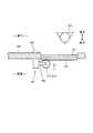
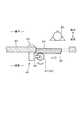
As shown in FIG. 2, the sliding door opening andclosing device 40 is attached to a slidingdoor 91 provided at an entrance of a living room or the like. In FIG. 2, the direction perpendicular to the paper surface is the opening / closing direction of the slidingdoor 91. The sliding door opening /closing device 40 allows the slidingdoor 91 in the room to be switched between an automatic door state that can be automatically opened and closed and a manual door state that can be manually opened and closed according to an instruction from themobile robot 20 or themonitoring device 30. In the case of the present embodiment, the sliding door opening /closing device 40 switches the slidingdoor 91 between the automatic door state and the manual door state according to an instruction from themobile robot 20 by directly communicating with themobile robot 20.

本実施形態において、自動扉状態とは、人が引戸91に触れることなくつまり人の力を引戸91に作用させることなく、引戸開閉装置40の作用によって引戸91を自動で開閉させることができる状態をいう。また、手動扉状態とは、人が引戸91に触れて人の力を作用させて引戸91を手動で開閉させることができる状態をいう。この場合、自動扉状態の概念としては、人が引戸91に大きな力を作用させて強制的に開閉することが可能な状態を含んでいても良い。すなわち、人が手動で引戸91を開閉させた場合、手動扉状態となっている引戸91の開閉に要する力は、自動扉状態になっている引戸91の開閉に要する力よりも小さい。つまり、引戸91が手動扉状態となっている場合、人は、引戸91が自動扉状態となっている場合に比べて小さな力で引戸91を開閉することができる。  In the present embodiment, the automatic door state refers to a state in which the slidingdoor 91 can be automatically opened and closed by the action of the sliding door opening andclosing device 40 without touching the slidingdoor 91, that is, without causing a human force to act on the slidingdoor 91. Say. Moreover, a manual door state means the state which a person touches the slidingdoor 91 and can make a person's force act and can open and close the slidingdoor 91 manually. In this case, the concept of the automatic door state may include a state in which a person can forcefully open and close the slidingdoor 91 by applying a large force. That is, when a person manually opens and closes the slidingdoor 91, the force required to open and close the slidingdoor 91 in the manual door state is smaller than the force required to open and close the slidingdoor 91 in the automatic door state. That is, when the slidingdoor 91 is in the manual door state, a person can open and close the slidingdoor 91 with a smaller force than when the slidingdoor 91 is in the automatic door state.

本実施形態において、引戸開閉装置40は、引戸91に対して事後的に取り付けられることにより、引戸91の外部から視認可能な位置に設けられている。すなわち、本実施形態の引戸開閉装置40は、引戸91に対して予め組み込まれているものではなく、既に手動扉状態として構成されている引戸91に対して事後的に取付可能となっている。なお、引戸開閉装置40は、引戸91に対して事後的に取り付けるものではなく、引戸91に対して予め組み込まれているものであっても良い。  In the present embodiment, the sliding door opening andclosing device 40 is provided at a position that is visible from the outside of the slidingdoor 91 by being attached to the slidingdoor 91 later. That is, the sliding door opening andclosing device 40 of the present embodiment is not incorporated in advance with respect to the slidingdoor 91 but can be attached to the slidingdoor 91 that is already configured as a manual door state. Note that the sliding door opening andclosing device 40 is not attached to the slidingdoor 91 afterwards, but may be built in the slidingdoor 91 in advance.

また、引戸開閉装置40を取り付ける引戸91は、図2に示すように、吊り下げ式の引戸であることが好ましい。本実施形態の場合、引戸91は、天井92又は上部の壁93に設けられたレール94に吊り下げられており、そのレール94に沿って開閉する。これは、吊り下げ式の引戸91は、吊り下げ式でない引戸つまり床面95に設置されたレールに沿って開閉する引戸に比べて、開閉に要する力が小さくて済むからである。これにより、引戸開閉装置40の出力を小さくすることができ、その結果、引戸開閉装置40のサイズや消費電力を抑えることができる。しかしながら、引戸開閉装置40が取付られる引戸91は、必ずしも吊り下げ式である必要はない。  Moreover, it is preferable that the slidingdoor 91 which attaches the sliding door opening /closing apparatus 40 is a suspension type sliding door, as shown in FIG. In the present embodiment, the slidingdoor 91 is suspended from arail 94 provided on theceiling 92 or theupper wall 93, and opens and closes along therail 94. This is because the suspensiontype sliding door 91 requires less force for opening and closing compared to a sliding door that is not a suspension type, that is, a sliding door that opens and closes along a rail installed on thefloor surface 95. Thereby, the output of the sliding door opening /closing apparatus 40 can be made small, As a result, the size and power consumption of the sliding door opening /closing apparatus 40 can be suppressed. However, the slidingdoor 91 to which the sliding door opening /closing device 40 is attached does not necessarily have to be a hanging type.

引戸開閉装置40は、図1及び図2に示すように、第4制御部41、引戸側送受信部42、モータ43、開閉検出部44、及び切替機構部45を有している。また、引戸開閉装置40は、図2に示すように、ラックギア46及びピニオンギア47を有している。ラックギア46とピニオンギア47とは相互に嵌合可能に構成されている。ラックギア46は、図2及び図9等に示すように、ラックギア46の長手方向が引戸91の開閉方向を向くように、引戸91の開閉方向に沿って引戸91に設けられている。  As shown in FIGS. 1 and 2, the sliding door opening /closing device 40 includes afourth control unit 41, a sliding door side transmission /reception unit 42, amotor 43, an opening /closing detection unit 44, and aswitching mechanism unit 45. Moreover, the sliding door opening andclosing apparatus 40 has arack gear 46 and apinion gear 47 as shown in FIG. Therack gear 46 and thepinion gear 47 are configured to be fitted to each other. Therack gear 46 is provided on the slidingdoor 91 along the opening / closing direction of the slidingdoor 91 so that the longitudinal direction of therack gear 46 faces the opening / closing direction of the slidingdoor 91 as shown in FIGS.

この場合、引戸開閉装置40の構成要素のうちラックギア46は、引戸91の上部に設けられている。一方、引戸開閉装置40の構成要素のうちラックギア46を除く構成要素、つまり第4制御部41、引戸側送受信部42、モータ43、開閉検出部44、及び切替機構部45は、引戸91の上部側の天井92又は壁93の壁面に設けられている。この場合、引戸開閉装置40は居室内のコンセントに接続されており、引戸開閉装置40の動作に必要な電力は、例えば居室内のコンセントから供給される。  In this case, among the components of the sliding door opening andclosing device 40, therack gear 46 is provided on the upper part of the slidingdoor 91. On the other hand, the components excluding therack gear 46 among the components of the sliding door opening andclosing device 40, that is, thefourth control unit 41, the sliding door side transmission /reception unit 42, themotor 43, the opening /closing detection unit 44, and theswitching mechanism unit 45 are the upper part of the slidingdoor 91. It is provided on thewall 92 of theside ceiling 92 orwall 93. In this case, the sliding door opening /closing device 40 is connected to an outlet in the living room, and the electric power necessary for the operation of the sliding door opening /closing device 40 is supplied from, for example, an outlet in the living room.

そして、ピニオンギア47は、モータ43の回転軸に設けられている。ラックギア46とピニオンギア47とが相互に嵌合した状態でモータ43を動作させると、モータ43の回転がピニオンギア47を介してラックギア46に伝達される。これにより、モータ43の回転方向に応じて、引戸91が自動で開閉される。  Thepinion gear 47 is provided on the rotation shaft of themotor 43. When themotor 43 is operated with therack gear 46 and thepinion gear 47 fitted to each other, the rotation of themotor 43 is transmitted to therack gear 46 via thepinion gear 47. Thereby, the slidingdoor 91 is automatically opened and closed according to the rotation direction of themotor 43.

第4制御部41は、引戸開閉装置40全体の制御を司っている。第4制御部41は、例えば図示しないCPUや、ROM、RAM、及び書き換え可能なフラッシュメモリ等の記憶領域を有するマイクロコンピュータを主体に構成されている。引戸側送受信部42、モータ43、開閉検出部44、及び切替機構部45は、それぞれ第4制御部41に電気的に接続されている。  Thefourth control unit 41 controls the entire sliding door opening /closing device 40. Thefourth control unit 41 is mainly configured by a microcomputer having a storage area such as a CPU (not shown), ROM, RAM, and rewritable flash memory. The sliding door side transmission /reception unit 42, themotor 43, the open /close detection unit 44, and theswitching mechanism unit 45 are each electrically connected to thefourth control unit 41.

引戸側送受信部42は、電気通信回線2を介さずに、外部の装置例えば移動ロボット20と直接的に通信可能な機能を有している。本実施形態の場合、引戸側送受信部42は、例えば赤外線信号を送受信することによって無線通信が可能ないわゆる赤外線通信機能を有している。引戸側送受信部42は、居室の外側つまり廊下側に設けられている。そして、引戸側送受信部42は、壁93内に通された電気配線によって、居室側に設けられた第4制御部41に接続されている。この場合、ロボット側送受信部27と引戸側送受信部42とは、壁93を隔てた状態での通信は不可能であるため、移動ロボット20が廊下側に存在している場合に限って相互間の通信が可能になる。  The sliding door side transmission /reception unit 42 has a function capable of directly communicating with an external device such as themobile robot 20 without using theelectric communication line 2. In the case of this embodiment, the sliding door side transmission /reception part 42 has what is called an infrared communication function in which wireless communication is possible by transmitting / receiving an infrared signal, for example. The sliding door side transmitting / receivingunit 42 is provided outside the living room, that is, on the hallway side. And the sliding door side transmission /reception part 42 is connected to the4th control part 41 provided in the living room side by the electrical wiring passed through thewall 93. In this case, the robot-side transmitter /receiver 27 and the sliding door-side transmitter /receiver 42 cannot communicate with each other with thewall 93 therebetween, and therefore, only when themobile robot 20 exists on the corridor side. Communication becomes possible.

なお、ロボット側送受信部27及び引戸側送受信部42は、赤外線通信機能に限られず、例えば電波や磁場を用いた近距離無線通信(NFC:Near Field Communication)等の機能を有するものであってもよい。この場合も、ロボット側送受信部27と引戸側送受信部42とは、壁93を隔てた状態での通信は不可能であるため、移動ロボット20が廊下側に存在している場合に限って、相互間の通信が可能となる。  The robot side transmitter /receiver 27 and the sliding door side transmitter /receiver 42 are not limited to the infrared communication function, and may have a function such as near field communication (NFC) using a radio wave or a magnetic field, for example. Good. Also in this case, the robot-side transceiver unit 27 and the sliding door-side transceiver unit 42 cannot communicate with each other across thewall 93, so only when themobile robot 20 exists on the corridor side, Communication between each other becomes possible.

また、ロボット側送受信部27及び引戸側送受信部42は、上述したものに限られず、例えば無線LANによって通信するものでも良い。この場合、ロボット側送受信部27と引戸側送受信部42とは、壁93を隔てた状態での通信が可能となるため、移動ロボット20が廊下側に存在している場合に限らず居室側に存在している場合においても、相互間の通信が可能となる。したがって、この場合、引戸側送受信部42は、居室内側に設けられていても良い。更に、引戸開閉装置40は、引戸側送受信部42に換えて又は引戸側送受信部42に加えて、電気通信回線2を介して外部の装置例えば移動ロボット20や監視装置30等と通信可能な通信部を有していても良い。  Moreover, the robot side transmission /reception unit 27 and the sliding door side transmission /reception unit 42 are not limited to those described above, and may communicate with each other by, for example, a wireless LAN. In this case, the robot-side transmitting / receivingunit 27 and the sliding door-side transmitting / receivingunit 42 can communicate with each other with thewall 93 therebetween, so that themobile robot 20 is not limited to the hallway side and is not limited to the living room side. Even when they exist, communication between them becomes possible. Therefore, in this case, the sliding door side transmitting / receivingunit 42 may be provided on the living room side. Further, the sliding door opening /closing device 40 can communicate with an external device such as themobile robot 20 or themonitoring device 30 via theelectric communication line 2 instead of or in addition to the sliding door side transmission /reception unit 42. It may have a part.

開閉検出部44は、引戸91の開状態及び閉状態を検出する機能を有している。開閉検出部44は、例えばモータ43の回転数を計測することで、引戸91の開閉状態を仮想的に検出するものである。また、開閉検出部44は、例えば引戸91又はラックギア46に設けられた近接センサや機械的スイッチで構成され、引戸91の開閉状態を直接的に検出するものであっても良い。  The open /close detection unit 44 has a function of detecting the open state and the closed state of the slidingdoor 91. The open /close detection unit 44 virtually detects the open / closed state of the slidingdoor 91 by, for example, measuring the number of rotations of themotor 43. The open /close detection unit 44 may be configured by, for example, a proximity sensor or a mechanical switch provided in the slidingdoor 91 or therack gear 46 and may directly detect the open / closed state of the slidingdoor 91.

切替機構部45は、例えば電動シリンダやソレノイドアクチュエータ等の駆動機構である。モータ43は、切替機構部45に設けられている。これにより、切替機構部45は、モータ43と共にピニオンギア47を移動させることができる。切替機構部45は、例えばモータ43を水平方向すなわち図2の左右方向へ移動させることで、ラックギア46とピニオンギア47とが嵌合した嵌合状態と、ラックギア46とピニオンギア47との嵌合が解除された非嵌合状態と、を切り替えることができる。  Theswitching mechanism unit 45 is a drive mechanism such as an electric cylinder or a solenoid actuator. Themotor 43 is provided in theswitching mechanism unit 45. As a result, theswitching mechanism 45 can move thepinion gear 47 together with themotor 43. Theswitching mechanism unit 45 moves, for example, themotor 43 in the horizontal direction, that is, the left-right direction in FIG. 2, so that therack gear 46 and thepinion gear 47 are fitted together, and therack gear 46 and thepinion gear 47 are fitted together. It is possible to switch between a non-fitted state in which is released.

ラックギア46とピニオンギア47とが嵌合した嵌合状態では、モータ43の回転がピニオンギア47を介してラックギア46に伝達可能となる。したがって、この嵌合状態では、引戸91は、引戸開閉装置40の作用つまりモータ43の作用によって自動で開閉される自動扉状態になっている。一方、ラックギア46とピニオンギア47との嵌合が解除された非嵌合状態では、モータ43の回転は、ラックギア46に伝達されない。この場合、モータ43の回転軸を外力によって回転させる際に生じる回転抵抗力も、ラックギア46に伝達されない。したがって、この非嵌合状態では、引戸91は、自動扉状態に比べてより小さい力で開閉可能な手動扉状態になっている。  In the fitting state in which therack gear 46 and thepinion gear 47 are fitted, the rotation of themotor 43 can be transmitted to therack gear 46 via thepinion gear 47. Therefore, in this fitted state, the slidingdoor 91 is in an automatic door state that is automatically opened and closed by the action of the sliding door opening andclosing device 40, that is, the action of themotor 43. On the other hand, the rotation of themotor 43 is not transmitted to therack gear 46 in a non-fitted state in which therack gear 46 and thepinion gear 47 are disengaged. In this case, the rotational resistance generated when the rotating shaft of themotor 43 is rotated by an external force is not transmitted to therack gear 46. Therefore, in this non-fitted state, the slidingdoor 91 is in a manual door state that can be opened and closed with a smaller force than in the automatic door state.

[各装置の制御及び動作内容]
次に、図3〜図15も参照して、各装置10、20、30、40の制御及び動作内容について説明する。各装置10、20、30、40は、各制御部11、21、31、41のCPUが各制御部11、21、31、41の記憶領域に記憶されているプログラムを実行することにより動作する。以下の説明では、制御を行う主体を各制御部11、21、31、41として説明する。
[Control and operation contents of each device]
Next, with reference to FIGS. 3 to 15 as well, the control and operation contents of thedevices 10, 20, 30, and 40 will be described. Eachdevice 10, 20, 30, 40 operates when the CPU of eachcontrol unit 11, 21, 31, 41 executes a program stored in the storage area of eachcontrol unit 11, 21, 31, 41. . In the following description, the main body that performs control will be described as eachcontrol unit 11, 21, 31, 41.

[生体情報取得装置の制御及び動作内容]
まず、生体情報取得装置10で行われる制御及び動作内容の一例について、図3を参照しながら説明する。本実施形態の場合、生体情報取得装置10は、監視対象者に異常が無い場合つまり生体情報取得部14で取得した生体情報が正常範囲内である場合には、所定時間毎、例えば1分間隔で生体情報を取得する。一方、監視対象者に異常が発生した場合つまり取得した生体情報が正常範囲を外れている場合には、監視装置30に対して異常信号を送信すると共に、生体情報を常時取得するようにする。これによれば、異常が発生していない通常時においては、生体情報取得部14の動作時間を低減することができるため、消費電力を抑えることができる。なお、生体情報取得装置10は、異常発生の有無に関わらず常に生体情報を取得する構成であっても良い。
[Control and operation contents of biometric information acquisition apparatus]
First, an example of control and operation contents performed in the biologicalinformation acquisition apparatus 10 will be described with reference to FIG. In the case of this embodiment, when there is no abnormality in the monitoring target person, that is, when the biological information acquired by the biologicalinformation acquisition unit 14 is within the normal range, the biologicalinformation acquisition device 10 is every predetermined time, for example, at an interval of 1 minute. To obtain biometric information. On the other hand, when an abnormality occurs in the monitoring subject, that is, when the acquired biological information is out of the normal range, an abnormal signal is transmitted to themonitoring device 30 and the biological information is always acquired. According to this, since the operation time of the biologicalinformation acquisition unit 14 can be reduced during normal times when no abnormality has occurred, power consumption can be suppressed. The biometricinformation acquisition device 10 may be configured to always acquire biometric information regardless of whether or not an abnormality has occurred.

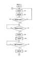
具体的には、生体情報取得装置10の第1制御部11は、図3に示すように、制御を開始すると(スタート)、ステップS11において生体情報取得部14を動作させて監視対象者の生体情報を取得する。次に、第1制御部11は、ステップS12において、異常信号が発信中であるか否かを判断する。異常信号が発信中である場合(ステップS12でYES)、第1制御部11は、ステップS16へ処理を移行させる。  Specifically, as illustrated in FIG. 3, thefirst control unit 11 of the biologicalinformation acquisition apparatus 10 starts control (start), and operates the biologicalinformation acquisition unit 14 in step S11 to operate the biological body of the monitoring target person. Get information. Next, the1st control part 11 judges whether the abnormal signal is transmitting in step S12. When the abnormal signal is being transmitted (YES in step S12), thefirst control unit 11 shifts the process to step S16.

一方、異常信号が発信中でない場合(ステップS12でNO)、第1制御部11は、ステップS13において、ステップS11で取得した生体情報の値が正常範囲内であるか否かを判断する。そして、生体情報の値が正常範囲内であれば(ステップS13でYES)、第1制御部11は、ステップS14において所定期間例えば1分間経過するまで待機し(ステップS14でNO)、所定期間経過した後に(ステップS14でYES)、ステップS11へ戻ってステップS11以降の処理を繰り返す。  On the other hand, when the abnormal signal is not being transmitted (NO in step S12), thefirst control unit 11 determines in step S13 whether the value of the biological information acquired in step S11 is within the normal range. If the value of the biological information is within the normal range (YES in step S13), thefirst control unit 11 waits until a predetermined period, for example, 1 minute elapses in step S14 (NO in step S14), and the predetermined period elapses. (YES in step S14), the process returns to step S11 to repeat the processes in and after step S11.

生体情報の値が正常範囲から外れている場合(ステップS13でNO)、第1制御部11は、監視対象者に異常が発生したと判断する。そして、第1制御部11は、ステップS15へ処理を移行させ、異常信号発信部15を動作させて異常信号を発信する。その後、第1制御部11は、ステップS16において位置情報取得部13を動作させて、生体情報取得装置10の位置つまり監視対象者の位置を取得する。そして、第1制御部11は、ステップS17において、第1通信部12を動作させて、異常信号及び位置情報や生体情報等の各種情報を、監視装置30へ送信する。なお、異常信号及び各種情報を、監視装置30に加えて移動ロボット20に送信しても良い。  When the value of the biological information is out of the normal range (NO in step S13), thefirst control unit 11 determines that an abnormality has occurred in the monitoring target person. And the1st control part 11 makes a process transfer to Step S15, operates abnormalsignal dispatch part 15, and transmits an abnormal signal. Then, the1st control part 11 operates positioninformation acquisition part 13 in Step S16, and acquires the position of living bodyinformation acquisition device 10, ie, the position of a monitoring subject. Then, in step S <b> 17, thefirst control unit 11 operates thefirst communication unit 12 to transmit an abnormal signal and various types of information such as position information and biological information to themonitoring device 30. The abnormal signal and various types of information may be transmitted to themobile robot 20 in addition to themonitoring device 30.

次に、第1制御部11は、ステップS18において解除信号を受信したか否かを判断する。解除信号は、ステップS15で発信した異常信号を停止させるための信号であり、本実施形態の場合、監視装置30から送信される。解除信号を受信している場合(ステップS18でYES)、第1制御部11は、ステップS19へ処理を移行させ、ステップS15で発信した異常信号を停止させる。一方、解除信号を受信していない場合(ステップS18でNO)、第1制御部11は、異常信号の発信を継続する。その後、第1制御部11は、ステップS11へ処理を移行させ、ステップS11以降の処理を繰り返す。  Next, the1st control part 11 judges whether the cancellation | release signal was received in step S18. The release signal is a signal for stopping the abnormal signal transmitted in step S15, and is transmitted from themonitoring device 30 in the present embodiment. When the cancellation signal is received (YES in step S18), thefirst control unit 11 shifts the process to step S19 and stops the abnormal signal transmitted in step S15. On the other hand, when the release signal is not received (NO in step S18), thefirst control unit 11 continues to transmit the abnormal signal. Thereafter, thefirst control unit 11 shifts the process to step S11 and repeats the processes after step S11.

[監視装置の制御及び動作内容]
次に、監視装置30で行われる制御及び動作内容の一例について、図4を参照しながら説明する。本実施形態の場合、監視装置30のモニタ33には、移動ロボット20のカメラ24で撮影された映像が表示されている。そして、生体情報取得装置10からの異常信号を受信すると、スピーカ25からその旨が報知されると共に、異常信号を発信した生体情報取得装置10から受信した生体情報や位置情報がモニタ33に表示される。
[Control and operation contents of monitoring device]
Next, an example of control and operation contents performed in themonitoring device 30 will be described with reference to FIG. In the case of the present embodiment, an image taken by thecamera 24 of themobile robot 20 is displayed on themonitor 33 of themonitoring device 30. When an abnormal signal is received from the biologicalinformation acquisition device 10, thespeaker 25 notifies the fact and the biological information and position information received from the biologicalinformation acquisition device 10 that has transmitted the abnormal signal are displayed on themonitor 33. The

具体的には、監視装置30の第3制御部31は、図4に示すように、制御を開始すると(スタート)、ステップS21においてモニタ33を動作させて、移動ロボット20のカメラ24で撮影した映像を表示する。次に、第3制御部31は、ステップS22において、生体情報取得装置10から異常信号を受信しているか否かを判断する。異常信号を受信していない場合(ステップS22でNO)、第3制御部31は、ステップS21へ処理を移行させ、ステップS21、22を繰り返す。一方、異常信号を受信した場合(ステップS22でYES)、第3制御部31は、ステップS23へ処理を移行させる。  Specifically, as shown in FIG. 4, thethird control unit 31 of themonitoring device 30 starts the control (start), operates themonitor 33 in step S <b> 21, and takes an image with thecamera 24 of themobile robot 20. Display video. Next, the3rd control part 31 judges whether the abnormal signal is received from the biometricinformation acquisition apparatus 10 in step S22. When the abnormal signal has not been received (NO in step S22), thethird control unit 31 shifts the process to step S21 and repeats steps S21 and S22. On the other hand, when an abnormal signal is received (YES in step S22), thethird control unit 31 shifts the process to step S23.

第3制御部31は、ステップS23においてスピーカ25を動作させて異常信号を受信した旨つまり監視対象者に異常が発生している旨を報知する。更に、第3制御部31は、ステップS24において、異常信号を発信した生体情報取得装置10から受信した生体情報や位置情報等の各種情報をモニタ33に表示させる。この場合、各種情報は、カメラ24で撮影した映像と共に、モニタ33に表示される。  Thethird control unit 31 operates thespeaker 25 in step S23 to notify that the abnormality signal has been received, that is, that the abnormality has occurred to the monitoring subject. Furthermore, the3rd control part 31 displays various information, such as biometric information received from the biometricinformation acquisition apparatus 10 which transmitted the abnormal signal, and positional information on themonitor 33 in step S24. In this case, various types of information are displayed on themonitor 33 together with the video shot by thecamera 24.

次に、第3制御部31は、ステップS25において、移動ロボット20に対して移動指令を送信済みであるか否かを判断する。移動指令とは、生体情報取得装置10から取得した位置情報に基づいて生成されるものであり、移動ロボット20を、異常信号を発信した生体情報取得装置10に向かって移動させるための指令信号である。この移動指令は、生体情報取得装置10の位置情報つまり移動ロボット20の目的地情報を含んでいる。  Next, the3rd control part 31 judges whether the movement command has been transmitted with respect to themobile robot 20 in step S25. The movement command is generated based on the position information acquired from the biologicalinformation acquisition device 10 and is a command signal for moving themobile robot 20 toward the biologicalinformation acquisition device 10 that has transmitted the abnormal signal. is there. This movement command includes the position information of the biologicalinformation acquisition apparatus 10, that is, the destination information of themobile robot 20.

移動指令が未だ送信されていない場合(ステップS25でNO)、第3制御部31は、ステップS26へ処理を移行させ、移動指令を生成して移動ロボット20に対してその移動指令を送信する。その後、第3制御部31は、ステップS27へ処理を移行させる。また、移動指令が既に送信されていた場合(ステップS25でYES)、第3制御部31は、ステップS26を実行することなく、ステップS27へ処理を移行させる。  When the movement command has not been transmitted yet (NO in step S25), thethird control unit 31 shifts the processing to step S26, generates the movement command, and transmits the movement command to themobile robot 20. Then, the3rd control part 31 makes a process transfer to step S27. If the movement command has already been transmitted (YES in step S25), thethird control unit 31 shifts the process to step S27 without executing step S26.

その後、第3制御部31は、ステップS27において異常解除の入力の有無を判断する。異常解除の入力とは、例えば監視者によって図示しない操作部に対して行われる入力操作である。異常解除の入力操作は、例えば監視者が監視対象者の状態を確認した場合等に行われる。この場合、異常解除の入力操作に用いられる図示しない操作部は、生体情報取得装置10、移動ロボット20、又は監視装置30のいずれに設けられていても良い。なお、異常解除の入力操作に用いられる操作部を生体情報取得装置10に設けることで、監視者は、異常解除の入力操作を行う際に、その生体情報取得装置10を装着している監視対象者に直接触れることになり、その結果、監視の信頼性の向上が図られる。  Thereafter, in step S27, thethird control unit 31 determines whether or not there is an input for abnormality cancellation. The abnormality canceling input is an input operation performed on an operation unit (not shown) by a supervisor, for example. The input operation for canceling the abnormality is performed, for example, when the monitoring person confirms the state of the monitoring target person. In this case, an operation unit (not shown) used for the input operation for canceling the abnormality may be provided in any of the biologicalinformation acquisition device 10, themobile robot 20, and themonitoring device 30. In addition, by providing the biologicalinformation acquisition apparatus 10 with an operation unit that is used for an input operation for canceling the abnormality, the monitor can monitor when the biologicalinformation acquisition apparatus 10 is mounted when performing an input operation for canceling the abnormality. As a result, the reliability of monitoring can be improved.

異常解除の入力があった場合(ステップS27でYES)、第3制御部31は、ステップS28において、異常信号を発信した生体情報取得装置10及び移動ロボット20に対して解除信号を送信する。その後、第3制御部31は、ステップS21へ戻り、ステップS21以降の処理を繰り返す。一方、異常解除の入力が無い場合(ステップS27でYES)、第3制御部31は、ステップS28を実行することなく、ステップS21へ戻ってステップS21以降の処理を繰り返す。  If there is an input for abnormality cancellation (YES in step S27), thethird control unit 31 transmits a cancellation signal to the biologicalinformation acquisition apparatus 10 and themobile robot 20 that have transmitted the abnormality signal in step S28. Then, the3rd control part 31 returns to step S21, and repeats the process after step S21. On the other hand, if there is no input for abnormality cancellation (YES in step S27), thethird control unit 31 returns to step S21 and repeats the processing from step S21 onward without executing step S28.

[移動ロボットの制御及び動作内容]
次に、移動ロボット20で行われる制御及び動作内容の一例について、図5及び図6等を参照しながら説明する。本実施形態の場合、移動ロボット20は、監視対象者に異常が無い場合つまり生体情報取得装置10又は監視装置30から異常信号の受信が無い場合には、予め設定されたルートを巡回して、監視対象となる領域内を満遍なく監視する。一方、移動ロボット20は、監視対象者に異常が発生した場合つまり生体情報取得装置10又は監視装置30から異常信号の受信を受けた場合には、その異常信号を発した生体情報取得装置10の現在位置を目的地として移動する。これにより、移動ロボット20は、その生体情報取得装置10の装着者つまり異常が発生した監視対象者を重点的に監視する。
[Control and operation of mobile robot]
Next, an example of control and operation contents performed by themobile robot 20 will be described with reference to FIGS. In the case of the present embodiment, when there is no abnormality in the monitoring target person, that is, when no abnormality signal is received from the biologicalinformation acquisition apparatus 10 or themonitoring apparatus 30, themobile robot 20 circulates a preset route, Monitor the entire area to be monitored evenly. On the other hand, when an abnormality occurs in the monitoring target person, that is, when the abnormal signal is received from the biologicalinformation acquisition device 10 or themonitoring device 30, themobile robot 20 receives the abnormal signal from the biologicalinformation acquisition device 10 that issued the abnormality signal. Move with the current position as the destination. Thereby, themobile robot 20 mainly monitors the wearer of the biometricinformation acquisition apparatus 10, that is, the monitoring target person in which the abnormality has occurred.

具体的には、移動ロボット20の第2制御部21は、図5に示すように、制御を開始すると(スタート)、ステップS31で移動機構部23を動作させて巡回動作を実行すると共に、ステップS32でカメラ24を動作させて周囲の映像を撮影する。次に、第2制御部21は、ステップS33において、生体情報取得装置10又は監視装置30から異常信号を受信したか否かを判断する。異常信号を受信していない場合(ステップS33でNO)、第2制御部21は、監視対象者に異常が発生していないと判断し、ステップS31、S32の処理を繰り返す。一方、異常信号を受信した場合(ステップS33でYES)、第2制御部21は、監視対象者に異常が発生したと判断し、ステップS34へ処理を移行させる。  Specifically, as shown in FIG. 5, when thesecond control unit 21 of themobile robot 20 starts control (start), the movingmechanism unit 23 is operated in step S31 to execute a patrol operation. In step S32, thecamera 24 is operated to capture a surrounding image. Next, the2nd control part 21 judges whether an abnormal signal was received from living bodyinformation acquisition device 10 ormonitoring device 30 in Step S33. If no abnormal signal has been received (NO in step S33), thesecond control unit 21 determines that no abnormality has occurred in the monitoring subject, and repeats the processes in steps S31 and S32. On the other hand, when an abnormal signal is received (YES in step S33), thesecond control unit 21 determines that an abnormality has occurred in the monitoring subject, and shifts the processing to step S34.

ステップS34において、第2制御部21は、監視装置30から移動指令を受信したか否かを判断し、移動指令を受信していない場合は(ステップS34でNO)、移動指令を受信するまで待機する。そして、第2制御部21は、監視装置30から移動指令を受信すると(ステップS34でYES)、ステップS35へ処理を移行させ、移動機構部23を動作させて移動を開始する。  In step S34, thesecond control unit 21 determines whether or not a movement command has been received from themonitoring device 30, and if no movement command has been received (NO in step S34), thesecond control unit 21 waits until a movement command is received. To do. When thesecond control unit 21 receives a movement command from the monitoring device 30 (YES in step S34), thesecond control unit 21 shifts the process to step S35, operates themovement mechanism unit 23, and starts moving.

移動ロボット20は、監視対象者の居室内に入室する際、図9に示すように、引戸91に対して所定距離L手前の位置で一旦停止する。そして、第2制御部21は、図5のステップS36における入室処理を実行する。入室処理が実行されると、第2制御部21は、図6のステップS361でロボット側送受信部27を動作させ、引戸開閉装置40の引戸側送受信部42に向けて入室要請信号を発信する。入室要請信号とは、移動ロボット20が入室を要請する際に発信する信号であり、引戸開閉装置40が引戸91を自動で開くためのトリガーとなる信号である。引戸開閉装置40によって引戸91が開かれて移動ロボット20が居室内に入室可能な状態になると、引戸開閉装置40から、入室許可信号が発信される。  When themobile robot 20 enters the monitoring subject's room, themobile robot 20 temporarily stops at a position a predetermined distance L before the slidingdoor 91 as shown in FIG. And the2nd control part 21 performs the room entrance process in FIG.5 S36. When the room entry process is executed, thesecond control unit 21 operates the robot side transmission /reception unit 27 in step S361 of FIG. 6 and transmits a room entry request signal to the sliding door side transmission /reception unit 42 of the sliding door opening /closing device 40. The room entry request signal is a signal transmitted when themobile robot 20 requests entry, and is a signal that triggers the sliding door opening /closing device 40 to automatically open the slidingdoor 91. When the slidingdoor 91 is opened by the sliding door opening /closing device 40 and themobile robot 20 is ready to enter the room, an entry permission signal is transmitted from the sliding door opening /closing device 40.

第2制御部21は、ステップS362において、引戸開閉装置40からの入室許可信号を受信したか否かを判断する。入室許可信号の受信が無い場合(ステップS362でNO)、第2制御部21は、ステップS363において所定時間が経過するまでステップS362、363を繰り返し、入室許可信号の受信を待つ。そして、入室許可信号を受信することなく所定時間が経過した場合(ステップS363でYES)、第2制御部21は、ステップS364において、第2通信部22を動作させて監視装置30に対して入室失敗信号を送信した後、監視者等による復帰操作を待つ。一方、第2制御部21は、入室許可信号を受信すると(ステップS362でYES)、ステップS365へ処理を移行させ、移動機構部23を動作させて、図12に示すように居室内に入室する。その後、第2制御部21は、図5のステップS37へ処理を移行させる(リターン)。  In Step S362, thesecond control unit 21 determines whether or not an entry permission signal from the sliding door opening /closing device 40 has been received. When no entry permission signal is received (NO in step S362), thesecond control unit 21 repeats steps S362 and 363 until a predetermined time elapses in step S363, and waits for reception of the entry permission signal. If the predetermined time has elapsed without receiving the entry permission signal (YES in step S363), thesecond control unit 21 operates thesecond communication unit 22 to enter themonitoring device 30 in step S364. After sending the failure signal, the system waits for a return operation by a supervisor or the like. On the other hand, when thesecond control unit 21 receives the room entry permission signal (YES in step S362), the process proceeds to step S365, and the movingmechanism unit 23 is operated to enter the room as shown in FIG. . Thereafter, thesecond control unit 21 shifts the processing to step S37 in FIG. 5 (return).

引戸開閉装置40は、移動ロボット20が居室内に入室している間は、引戸91を開放状態に維持する。第2制御部21は、ステップS37において、生体情報取得装置10又は監視装置30から解除信号を受信したか否かを判断し、解除信号を受信するまでその場で待機する(ステップS37でNO)。そして、解除信号を受信すると(ステップS37でYES)、第2制御部21は、ステップS38へ処理を移行させ、退室処理を実行する。  The sliding door opening /closing device 40 maintains the slidingdoor 91 in an open state while themobile robot 20 enters the room. In step S37, thesecond control unit 21 determines whether or not a release signal is received from the biologicalinformation acquisition device 10 or themonitoring device 30, and waits on the spot until the release signal is received (NO in step S37). . When the release signal is received (YES in step S37), thesecond control unit 21 shifts the process to step S38, and executes a room leaving process.

退室処理が実行されると、第2制御部21は、図7のステップS381で移動機構部23を動作させて、図13に示すように移動ロボット20を居室外へ退室させる。第2制御部21は、ステップS382において移動機構部23を制御し、図13に示すように、移動ロボット20を引戸91に対して所定距離L手前の位置で一旦停止させる。その後、第2制御部21は、図7のステップS383においてロボット側送受信部27を動作させ、引戸開閉装置40の引戸側送受信部42に向けて退室完了信号を発信する。退室完了信号とは、移動ロボット20が退室を完了した際に発信する信号であり、引戸開閉装置40が引戸91を自動で閉じるためのトリガーとなる信号である。引戸開閉装置40によって引戸91が閉じられると、引戸開閉装置40の引戸側送受信部42から、引戸91の閉鎖が完了した旨を示す閉鎖完了信号が発信される。  When the room leaving process is executed, thesecond control unit 21 operates the movingmechanism unit 23 in step S381 in FIG. 7 to cause themobile robot 20 to leave the room as shown in FIG. Thesecond control unit 21 controls the movingmechanism unit 23 in step S382 to temporarily stop themobile robot 20 at a position a predetermined distance L before the slidingdoor 91 as shown in FIG. Then, the2nd control part 21 operates the robot side transmission /reception part 27 in FIG.7 S383, and transmits the leaving completion signal toward the sliding door side transmission /reception part 42 of the sliding door opening /closing apparatus 40. FIG. The exit signal is a signal that is transmitted when themobile robot 20 completes leaving, and is a signal that triggers the sliding door opening /closing device 40 to automatically close the slidingdoor 91. When the slidingdoor 91 is closed by the sliding door opening /closing device 40, a closing completion signal indicating that the closing of the slidingdoor 91 is completed is transmitted from the sliding door side transmission /reception unit 42 of the sliding door opening /closing device 40.

その後、第2制御部21は、ステップS384において、引戸開閉装置40から閉鎖完了信号を受信したか否かを判断する。閉鎖完了信号を受信すると(ステップS384でYES)、第2制御部21は、図5のステップS31へ移行し、巡回動作を再開する。一方、閉鎖完了信号の受信が無い場合(図7のステップS384でNO)、第2制御部21は、所定時間が経過するまでステップS384、385を繰り返し、閉鎖完了信号の受信を待つ。そして、閉鎖完了信号を受信することなく所定期間が経過した場合(ステップS385でYES)、第2制御部21は、ステップ386において、第2通信部22を動作させて、監視装置30に対して、引戸91の閉鎖が失敗された旨を示す閉鎖失敗信号を送信する。そして、第2制御部21は、図5のステップS31へ移行し、巡回動作を再開する。  Thereafter, thesecond control unit 21 determines whether or not a closing completion signal has been received from the sliding door opening andclosing device 40 in step S384. When the closing completion signal is received (YES in step S384), thesecond control unit 21 proceeds to step S31 in FIG. 5 and restarts the patrol operation. On the other hand, when the closing completion signal is not received (NO in step S384 in FIG. 7), thesecond control unit 21 repeats steps S384 and 385 until a predetermined time elapses and waits for the reception of the closing completion signal. If the predetermined period has elapsed without receiving the closing completion signal (YES in step S385), thesecond control unit 21 operates thesecond communication unit 22 in step 386 to themonitoring device 30. Then, a closing failure signal indicating that the closing of the slidingdoor 91 has failed is transmitted. And the2nd control part 21 transfers to step S31 of FIG. 5, and restarts cyclic operation.

[引戸開閉装置の制御及び動作内容]
次に、引戸開閉装置40で行われる制御及び動作内容の一例について、図8〜図15を参照しながら説明する。なお、図10〜図15における白抜き矢印は、各要素の移動又は駆動方向を示している。また、図9〜図15における「前方」及び「後方」は、移動ロボット20の「前方」及び「後方」を示している。また、以下の説明では、引戸91を開く際のモータ43の回転方向を正回転とし、引戸91を閉じる際のモータ43の回転方向を逆回転とする。
[Control and operation of sliding door opening and closing device]
Next, an example of control and operation contents performed by the sliding door opening andclosing device 40 will be described with reference to FIGS. In addition, the white arrow in FIGS. 10-15 has shown the movement or drive direction of each element. Further, “front” and “rear” in FIGS. 9 to 15 indicate “front” and “rear” of themobile robot 20. In the following description, the rotation direction of themotor 43 when opening the slidingdoor 91 is assumed to be normal rotation, and the rotation direction of themotor 43 when closing the slidingdoor 91 is assumed to be reverse rotation.

本実施形態の場合、引戸開閉装置40は、移動ロボット20から入室要請信号を受信するまでは、引戸91を手動扉状態に維持する。そして、引戸開閉装置40は、移動ロボット20から入室要請信号を受信すると、引戸91の閉鎖が完了して閉鎖完了信号を送信するまで、引戸91を自動扉状態に維持する。  In the case of the present embodiment, the sliding door opening /closing device 40 maintains the slidingdoor 91 in the manual door state until receiving an entry request signal from themobile robot 20. And the sliding door opening /closing apparatus 40 will maintain the slidingdoor 91 in an automatic door state until the closing of the slidingdoor 91 is completed and a closing completion signal is transmitted, if the entrance request signal is received from themobile robot 20.

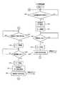
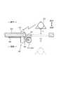
具体的には、引戸開閉装置40の第4制御部41は、図8に示すように、制御を開始すると(スタート)、ステップS41において引戸側送受信部42を動作させて、移動ロボット20から入室要請信号を受信したか否かを判断する。入室要請信号の受信が無い場合(ステップS41でNO)、第4制御部41は、引戸91を手動扉状態にしたまま待機する。一方、第4制御部41は、図9に示すように、入室要請信号を受信すると(ステップS41でYES)、ステップS42において切替機構部45を動作させて切替動作を実行する。この場合、切替機構部45は、図10に示すように、モータ43をラックギア46側へ移動させることでピニオンギア47とラックギア46と嵌合させ、これにより引戸91を手動扉状態から自動扉状態に切り替える。  Specifically, as shown in FIG. 8, thefourth control unit 41 of the sliding door opening /closing device 40 starts control (start) and operates the sliding door side transmission /reception unit 42 to enter the room from themobile robot 20 in step S41. It is determined whether a request signal is received. When no entry request signal is received (NO in step S41), thefourth control unit 41 stands by with the slidingdoor 91 in the manual door state. On the other hand, as shown in FIG. 9, when thefourth control unit 41 receives the room entry request signal (YES in step S41), thefourth control unit 41 operates theswitching mechanism unit 45 in step S42 to execute the switching operation. In this case, as shown in FIG. 10, theswitching mechanism unit 45 moves themotor 43 to therack gear 46 side so that thepinion gear 47 and therack gear 46 are engaged, thereby moving the slidingdoor 91 from the manual door state to the automatic door state. Switch to.

その後、第4制御部41は、図8のステップS43においてモータ43を正回転させる。これにより、図11に示すように、引戸91が自動で開かれる。第4制御部41は、開閉検出部44によって引戸91が開いたことを検出するまでは、モータ43の駆動を継続させる(図8のステップS44でNO)。そして、第4制御部41は、開閉検出部44によって引戸91が開いたことを検出すると(ステップS44でYES)、ステップS45においてモータ43を停止させる。その後、第4制御部41は、図11に示すように、引戸側送受信部42を動作させて移動ロボット20に向けて入室許可信号を発信する。そして、入室許可信号を受信した移動ロボット20は、図12に示すように、居室内に入室する。  Thereafter, thefourth control unit 41 rotates themotor 43 forward in step S43 of FIG. Thereby, as shown in FIG. 11, the slidingdoor 91 is automatically opened. Thefourth control unit 41 continues to drive themotor 43 until the opening /closing detection unit 44 detects that the slidingdoor 91 is opened (NO in step S44 of FIG. 8). And if the4th control part 41 detects that the slidingdoor 91 opened by the opening / closing detection part 44 (it is YES at step S44), themotor 43 will be stopped in step S45. Thereafter, as shown in FIG. 11, thefourth control unit 41 operates the sliding door side transmission /reception unit 42 to transmit a room permission signal toward themobile robot 20. Then, themobile robot 20 that has received the room entry permission signal enters the room as shown in FIG.

その後、第4制御部41は、図8のステップS47において、移動ロボット20から退室完了信号を受信したか否かを判断する。第4制御部41は、退室完了信号を受信するまで待機する(ステップS47でNO)。そして、第4制御部41は、図13に示すように移動ロボット20から退室完了信号を受信すると(図8のステップS47でYES)、ステップS48においてモータ43を逆回転させて引戸91を閉じる。第4制御部41は、開閉検出部44によって引戸91が閉鎖されたことを検出するまでは、モータ43の駆動を継続させる(ステップS49でNO)。  Thereafter, thefourth control unit 41 determines whether or not a room exit completion signal has been received from themobile robot 20 in step S47 of FIG. Thefourth control unit 41 waits until it receives a leaving completion signal (NO in step S47). And if the4th control part 41 receives the leaving completion signal from themobile robot 20 as shown in FIG. 13 (it is YES at step S47 of FIG. 8), themotor 43 will reversely rotate in step S48, and the slidingdoor 91 will be closed. Thefourth control unit 41 continues to drive themotor 43 until the opening /closing detection unit 44 detects that the slidingdoor 91 is closed (NO in step S49).

そして、第4制御部41は、開閉検出部44によって引戸91が閉じたことを検出すると(ステップS49でYES)、ステップS50においてモータ43を停止させる。その後、第4制御部41は、ステップS51において切替機構部45を動作させて切替動作を実行する。この場合、切替機構部45は、図15に示すように、モータ43をラックギア46から離間する方向へ移動させることでピニオンギア47とラックギア46との嵌合を解除し、これにより引戸91を自動扉状態から手動扉状態に切り替える。そして、第4制御部41は、図8のステップS52において引戸側送受信部42を動作させて、図15に示すように移動ロボット20側へ向けて閉鎖完了信号を発信する。その後、第4制御部41は、図8のステップS41へ処理を戻し、ステップS41以降の処理を繰り返す。  And if the4th control part 41 detects that the slidingdoor 91 closed by the opening / closing detection part 44 (it is YES at step S49), themotor 43 will be stopped in step S50. Thereafter, thefourth control unit 41 operates theswitching mechanism unit 45 in step S51 to execute the switching operation. In this case, as shown in FIG. 15, theswitching mechanism unit 45 moves themotor 43 in a direction away from therack gear 46 to release the fitting between thepinion gear 47 and therack gear 46, thereby automatically moving the slidingdoor 91. Switch from door state to manual door state. And the4th control part 41 operates the sliding door side transmission /reception part 42 in FIG.8 S52, and transmits the closing completion signal toward themobile robot 20 side, as shown in FIG. Thereafter, thefourth control unit 41 returns the process to step S41 of FIG. 8, and repeats the processes after step S41.

以上説明した実施形態によれば、監視システム1は、生体情報取得装置10で取得した監視対象者の生体情報に基づいて異常を判断する。したがって、監視対象者の異常状態を直接的に検出することができる。そして、生体情報取得装置10を装着している監視対象者に異常が生じた場合、移動ロボット20が、その異常が生じた監視対象者を目指して移動する。これにより、監視者は、監視対象者から離れた遠隔地においても、監視装置30のモニタ33を見ることで監視対象者の異常状態をいち早く確認することができる。  According to the embodiment described above, the monitoring system 1 determines an abnormality based on the biological information of the monitoring subject acquired by the biologicalinformation acquisition device 10. Therefore, it is possible to directly detect the abnormal state of the monitoring subject. When an abnormality occurs in the monitoring subject wearing the biologicalinformation acquisition apparatus 10, themobile robot 20 moves toward the monitoring subject in which the abnormality has occurred. Thus, the monitor can quickly confirm the abnormal state of the monitoring target person by looking at themonitor 33 of themonitoring device 30 even in a remote place away from the monitoring target person.

監視システム1は、複数の生体情報取得装置10を備えている。そして、複数の生体情報取得装置10は、それぞれ異なる監視対象者に装着される。すなわち、監視システム1は、1台の監視装置30で、複数の監視対象者を監視することができる。これによれば、例えば病院や介護施設等のように、多数の監視対象者を監視する必要がある場合であっても、少人数の監視者で対応することができ、その結果、監視に要する人員を削減することができる。  The monitoring system 1 includes a plurality of biologicalinformation acquisition devices 10. The plurality of biologicalinformation acquisition devices 10 are attached to different monitoring subjects. That is, the monitoring system 1 can monitor a plurality of monitoring subjects with onemonitoring device 30. According to this, even when it is necessary to monitor a large number of monitoring subjects, such as hospitals and care facilities, it is possible to handle with a small number of monitoring personnel, and as a result, monitoring is required. Personnel can be reduced.

ここで、移動ロボット20を居室に入退室させるためには、引戸91を開閉させる必要がある。この場合、例えば引戸91を一般的な自動ドアにしたり、移動ロボット20に引戸91の開閉用のアーム等を設けたりすることが考えられる。しかしながら、例えば引戸91を自動ドアにすると、引戸91の前を人が通るたびに引戸91が開閉してしまう。したがって、自動ドアにすることは、居室用の引戸91としては不向きである。また、移動ロボット20に引戸91の開閉用のアーム等を設けると、移動ロボット20の構成や制御が複雑になり、移動ロボット20のコストも上昇する。  Here, in order to move themobile robot 20 into and out of the room, it is necessary to open and close the slidingdoor 91. In this case, for example, the slidingdoor 91 may be a general automatic door, or themobile robot 20 may be provided with an arm for opening and closing the slidingdoor 91. However, for example, when the slidingdoor 91 is an automatic door, the slidingdoor 91 opens and closes every time a person passes in front of the slidingdoor 91. Therefore, using an automatic door is not suitable as a slidingdoor 91 for a living room. If themobile robot 20 is provided with an arm for opening and closing the slidingdoor 91, the configuration and control of themobile robot 20 become complicated, and the cost of themobile robot 20 also increases.

そこで、本実施形態において、監視システム1は、引戸開閉装置40を更に備える。引戸開閉装置40は、移動ロボット20又は監視装置30からの指示により、居室の引戸91を自動で開閉可能な自動扉状態と手動で開閉可能な手動扉状態と切り替える。これによれば、引戸91は、移動ロボット20が入退室する際に引戸91を自動扉状態にし、その他の場合には引戸91を手動扉状態にすることができる。したがって、監視システム1は、引戸91を一般的な自動ドアにしたり、移動ロボット20に引戸91の開閉用のアーム等を設けたりした場合に生じ得る上述した不都合を回避することができ、その結果、自動扉状態と手動扉状態の両方のメリットを得ることができる。  Therefore, in the present embodiment, the monitoring system 1 further includes a sliding door opening /closing device 40. The sliding door opening /closing device 40 switches between an automatic door state in which the slidingdoor 91 in the room can be automatically opened and closed and a manual door state in which the door can be manually opened / closed in accordance with an instruction from themobile robot 20 or themonitoring device 30. According to this, the slidingdoor 91 can make the slidingdoor 91 into an automatic door state when themobile robot 20 enters and leaves the room, and can make the slidingdoor 91 into a manual door state in other cases. Therefore, the monitoring system 1 can avoid the above-described inconvenience that may occur when the slidingdoor 91 is a general automatic door or themobile robot 20 is provided with an arm for opening and closing the slidingdoor 91. The advantages of both the automatic door state and the manual door state can be obtained.

移動ロボット20及び引戸開閉装置40は、それぞれ赤外線信号を送受信することによって相互に無線通信可能な送受信部27、42を有している。これによれば、移動ロボット20と引戸開閉装置40との通信に電波を使用するものに比べて、比較的安価に構成することができる。更に、電波を使用した無線通信の場合、移動ロボット20は、常に全ての引戸開閉装置40と通信状態を維持しなければならず、そのため、電波帯域を無駄に使用すると共に消費電力の無駄も大きくなる。しかし、本実施形態のように、赤外線通信によって1対1の通信を可能にすることで、電波帯域を無駄に使用することもなく、消費電力も低減することができる。これは、引戸開閉装置40の数が増大した場合すなわち監視対象者が増大した場合により有効である。  Themobile robot 20 and the sliding door opening /closing device 40 have transmission /reception units 27 and 42 that can wirelessly communicate with each other by transmitting and receiving infrared signals. According to this, compared with what uses an electromagnetic wave for communication with themobile robot 20 and the sliding door opening /closing apparatus 40, it can comprise at comparatively low cost. Furthermore, in the case of wireless communication using radio waves, themobile robot 20 must always maintain communication with all the sliding door opening /closing devices 40, so that the radio band is wasted and power consumption is wasted. Become. However, by enabling one-to-one communication by infrared communication as in the present embodiment, the radio wave band is not wasted and power consumption can be reduced. This is more effective when the number of sliding door opening /closing devices 40 increases, that is, when the number of monitoring subjects increases.

引戸開閉装置40は、引戸91の外部から視認可能な位置に設けられている。すなわち、本実施形態の場合、引戸開閉装置40は、引戸91の内部に予め組み込まれたものではなく、引戸91の外部から取り付け可能となっている。すなわち、本実施形態の引戸開閉装置40は、当初は手動専用であった引戸91に対して事後的に取り付けることができる。これによれば、当初は監視システム1の適用を想定しておらず、手動専用の引戸91を有している施設に対しても、引戸91に引戸開閉装置40を取り付けることで、その引戸91を監視システム1に適用させることができる。また、これによれば、引戸開閉装置40を取り外すことも容易となるため、引戸開閉装置40のメンテナンスや引戸91を手動専用に戻すことが容易になる。  The sliding door opening andclosing device 40 is provided at a position that can be seen from the outside of the slidingdoor 91. That is, in the case of this embodiment, the sliding door opening andclosing device 40 is not incorporated in advance inside the slidingdoor 91 but can be attached from the outside of the slidingdoor 91. That is, the sliding door opening andclosing device 40 of this embodiment can be attached afterwards to the slidingdoor 91 that was originally dedicated to manual operation. According to this, the application of the monitoring system 1 is not initially assumed, and the slidingdoor 91 is attached to the slidingdoor 91 by attaching the sliding door opening /closing device 40 to a facility having the manual slidingdoor 91. Can be applied to the monitoring system 1. Moreover, since it becomes easy to remove the sliding door opening /closing apparatus 40 according to this, it becomes easy to return the maintenance of the sliding door opening /closing apparatus 40 and the slidingdoor 91 to manual exclusive use.

そして、引戸開閉装置40は、引戸側送受信部42と、ラックギア46と、ピニオンギア47と、モータ43と、切替機構部45と、を有している。この場合、引戸側送受信部42は、例えば外部装置すなわち移動ロボット20からの信号を受信可能な受信部として機能する。そして、切替機構部45は、引戸側送受信部42で受信した信号に基づいてモータ43を移動させてラックギア46とピニオンギア47との嵌合状態を切り替えることで、引戸91を自動扉状態と手動扉状態とに切り替える。これによれば、引戸開閉装置40を比較的簡単な構成とすることができる。  The sliding door opening andclosing device 40 includes a sliding door side transmission /reception unit 42, arack gear 46, apinion gear 47, amotor 43, and aswitching mechanism unit 45. In this case, the sliding door side transmitting / receivingunit 42 functions as a receiving unit capable of receiving a signal from, for example, an external device, that is, themobile robot 20. Then, theswitching mechanism unit 45 moves themotor 43 based on the signal received by the sliding door side transmitting / receivingunit 42 to switch the fitting state between therack gear 46 and thepinion gear 47, thereby changing the slidingdoor 91 from the automatic door state to the manual door state. Switch to the door state. According to this, the sliding door opening andclosing apparatus 40 can be made a relatively simple configuration.

なお、本発明の実施形態は、上記し且つ図面に記載した各実施形態に限定されるものではなく、発明の要旨を逸脱しない範囲において適宜変更することができる。  The embodiments of the present invention are not limited to the embodiments described above and illustrated in the drawings, and can be modified as appropriate without departing from the scope of the invention.

図面中、1は監視システム、2は電気通信回線、10は生体情報取得装置、12は第1通信部、14は生体情報取得部、15は異常信号発信部、20は移動ロボット、22は第2通信部、23は移動機構部、24はカメラ、30は監視装置、32は第3通信部、33はモニタ、40は引戸開閉装置、42は引戸側送受信部(送受信部、受信部)、43はモータ、45は切替機構部、46はラックギア、47はピニオンギアを示す。  In the drawings, 1 is a monitoring system, 2 is a telecommunication line, 10 is a biological information acquisition device, 12 is a first communication unit, 14 is a biological information acquisition unit, 15 is an abnormal signal transmission unit, 20 is a mobile robot, and 22 is a first 2 communication units, 23 a moving mechanism unit, 24 a camera, 30 a monitoring device, 32 a third communication unit, 33 a monitor, 40 a sliding door opening / closing device, 42 a sliding door side transmission / reception unit (transmission / reception unit, reception unit),Reference numeral 43 denotes a motor, 45 a switching mechanism, 46 a rack gear, and 47 a pinion gear.

Claims (8)

Translated fromJapanese
監視対象者の生体情報を取得可能な生体情報取得部と、電気通信回線を通じて通信可能な第1通信部と、前記生体情報が予め設定された正常範囲から外れた場合に異常信号を発信する異常信号発信部と、を有し、前記監視対象者に装着可能な生体情報取得装置と、
前記電気通信回線を通じて通信可能な第2通信部と、特定の領域内を自律的に移動可能な移動機構部と、前記移動機構部の周囲を撮影可能なカメラと、を有する移動ロボットと、
前記電気通信回線を通じて通信可能な第3通信部と、前記カメラで撮影した画像又は映像を表示可能なモニタと、を有する監視装置と、を備え、
前記移動ロボットは、前記異常信号を受信した場合に前記異常信号が発信された前記生体情報取得装置を目指して移動する、
監視システム。
A biological information acquisition unit capable of acquiring biological information of a monitoring subject, a first communication unit capable of communicating through an electric communication line, and an abnormality that transmits an abnormal signal when the biological information is out of a preset normal range A biological information acquisition device having a signal transmission unit and attachable to the monitoring subject,
A mobile robot having a second communication unit capable of communicating through the telecommunication line, a moving mechanism unit capable of autonomously moving in a specific area, and a camera capable of photographing the periphery of the moving mechanism unit;
A third communication unit capable of communicating through the telecommunication line, and a monitor capable of displaying an image or video captured by the camera,
The mobile robot moves toward the biological information acquisition device from which the abnormal signal is transmitted when the abnormal signal is received;
Monitoring system.
複数の前記生体情報取得装置を備えている、
請求項1に記載の監視システム。
A plurality of the biological information acquisition devices;
The monitoring system according to claim 1.
前記移動ロボット又は前記監視装置からの指示により引戸を自動で開閉可能な自動扉状態と手動で開閉可能な手動扉状態とに切替可能な引戸開閉装置を更に備える、
請求項1又は2に記載の監視システム。
A sliding door opening / closing device capable of switching between an automatic door state capable of automatically opening and closing a sliding door and a manual door state capable of being manually opened / closed by an instruction from the mobile robot or the monitoring device;
The monitoring system according to claim 1 or 2.
前記移動ロボット及び前記引戸開閉装置は、赤外線信号を送受信することによって相互に無線通信可能な送受信部をそれぞれ有している、
請求項3に記載の監視システム。
The mobile robot and the sliding door opening and closing device each have a transmitting / receiving unit capable of wireless communication with each other by transmitting and receiving infrared signals.
The monitoring system according to claim 3.
前記引戸開閉装置は、前記引戸の外部から視認可能な位置に設けられている、
請求項3又は4に記載の監視システム。
The sliding door opening and closing device is provided at a position visible from the outside of the sliding door,
The monitoring system according to claim 3 or 4.
外部装置からの信号を受信可能な受信部と、
引戸の開閉方向に沿って前記引戸に設けられるラックギアと、
前記ラックギアに嵌合可能なピニオンギアと、
前記ピニオンギアを回転駆動させるモータと、
前記受信部で受信した信号に基づいて、前記ラックギアと前記ピニオンギアとが嵌合して前記モータの回転が前記ラックギアに伝達されることにより前記引戸を自動で開閉可能な自動扉状態と、前記ラックギアと前記ピニオンギアとの嵌合が解除されることにより前記引戸を手動で開閉可能な手動扉状態と、を切替可能な切替機構部と、
を備える引戸開閉装置。
A receiving unit capable of receiving a signal from an external device;
A rack gear provided in the sliding door along the opening and closing direction of the sliding door;
A pinion gear that can be fitted to the rack gear;
A motor that rotationally drives the pinion gear;
Based on the signal received by the receiver, the rack gear and the pinion gear are engaged, and the rotation of the motor is transmitted to the rack gear so that the sliding door can be automatically opened and closed, and A switching mechanism portion capable of switching between a manual door state in which the sliding door can be manually opened and closed by releasing the fitting of the rack gear and the pinion gear;
A sliding door opening and closing device.
前記受信部は、赤外線信号を受信するものである、
請求項6に記載の引戸開閉装置。
The receiver is for receiving an infrared signal.
The sliding door opening and closing device according to claim 6.
前記引戸開閉装置は、前記引戸に対し前記引戸の外部から視認可能な位置に取り付け可能である、
請求項6又は7に記載の引戸開閉装置。
The sliding door opening and closing device can be attached to the sliding door at a position that is visible from the outside of the sliding door.
The sliding door opening and closing device according to claim 6 or 7.
JP2016097061A2016-05-132016-05-13 Monitoring systemActiveJP6730087B2 (en)

Priority Applications (1)

Application NumberPriority DateFiling DateTitle
JP2016097061AJP6730087B2 (en)2016-05-132016-05-13 Monitoring system

Applications Claiming Priority (1)

Application NumberPriority DateFiling DateTitle
JP2016097061AJP6730087B2 (en)2016-05-132016-05-13 Monitoring system

Related Child Applications (1)

Application NumberTitlePriority DateFiling Date
JP2020109585ADivisionJP6867721B2 (en)2020-06-252020-06-25 Monitoring system

Publications (2)

Publication NumberPublication Date
JP2017204228Atrue JP2017204228A (en)2017-11-16
JP6730087B2 JP6730087B2 (en)2020-07-29

Family

ID=60323296

Family Applications (1)

Application NumberTitlePriority DateFiling Date
JP2016097061AActiveJP6730087B2 (en)2016-05-132016-05-13 Monitoring system

Country Status (1)

CountryLink
JP (1)JP6730087B2 (en)

Cited By (4)

* Cited by examiner, † Cited by third party
Publication numberPriority datePublication dateAssigneeTitle
CN112065209A (en)*2020-10-122020-12-11江西沃尔特铝业有限公司Intelligent home position analysis automatic door opening system for intelligent door and window
CN112502566A (en)*2020-11-172021-03-16广州赛特智能科技有限公司Method and system for assisting robot to pass through electric door
CN114281005A (en)*2021-12-312022-04-05浙江孚宝智能科技有限公司Opening method of induction door and storage medium
CN117468824A (en)*2023-10-112024-01-30浙江华正检测有限公司 Indoor air quality automatic detection system and detection method

Citations (14)

* Cited by examiner, † Cited by third party
Publication numberPriority datePublication dateAssigneeTitle
JPH04120878U (en)*1991-04-181992-10-28株式会社富士通ゼネラル automatic door
JPH0928681A (en)*1995-07-141997-02-04Matsushita Electric Ind Co Ltd Safety confirmation system
JPH10234681A (en)*1997-02-241998-09-08Toshio Fukuda Nursing care robot and care system
JPH11283152A (en)*1998-03-271999-10-15Sharp Corp Remote control system
JPH11324483A (en)*1998-05-111999-11-26Royal Electric Co LtdAutomatic door and opening/closing device thereof
JP2001112725A (en)*1999-10-152001-04-24Dia Syst KkBiological information measuring apparatus
JP2001280001A (en)*2000-03-302001-10-10Delta Kogyo Co Ltd Door openers
JP2002097840A (en)*2000-09-272002-04-05Toyo Shutter Co LtdDrive unit for double sliding shoji (japanese paper screen door)
JP2003051083A (en)*2001-08-072003-02-21Omron CorpDevice, method, program and system for collecting information and recording medium recorded with information collection program
US20070085690A1 (en)*2005-10-162007-04-19Bao TranPatient monitoring apparatus
JP2009181270A (en)*2008-01-302009-08-13Secom Co Ltd Mobile robot
KR20090129550A (en)*2008-06-132009-12-17주식회사 건축과 환경 Optional automatic windows and doors
US20120165984A1 (en)*2010-12-232012-06-28Electronics And Telecommunications Research InstituteMobile robot apparatus, door control apparatus, and door opening and closing method therefor
CN104301683A (en)*2014-10-222015-01-21五邑大学 Elderly home safety protection system

Patent Citations (14)

* Cited by examiner, † Cited by third party
Publication numberPriority datePublication dateAssigneeTitle
JPH04120878U (en)*1991-04-181992-10-28株式会社富士通ゼネラル automatic door
JPH0928681A (en)*1995-07-141997-02-04Matsushita Electric Ind Co Ltd Safety confirmation system
JPH10234681A (en)*1997-02-241998-09-08Toshio Fukuda Nursing care robot and care system
JPH11283152A (en)*1998-03-271999-10-15Sharp Corp Remote control system
JPH11324483A (en)*1998-05-111999-11-26Royal Electric Co LtdAutomatic door and opening/closing device thereof
JP2001112725A (en)*1999-10-152001-04-24Dia Syst KkBiological information measuring apparatus
JP2001280001A (en)*2000-03-302001-10-10Delta Kogyo Co Ltd Door openers
JP2002097840A (en)*2000-09-272002-04-05Toyo Shutter Co LtdDrive unit for double sliding shoji (japanese paper screen door)
JP2003051083A (en)*2001-08-072003-02-21Omron CorpDevice, method, program and system for collecting information and recording medium recorded with information collection program
US20070085690A1 (en)*2005-10-162007-04-19Bao TranPatient monitoring apparatus
JP2009181270A (en)*2008-01-302009-08-13Secom Co Ltd Mobile robot
KR20090129550A (en)*2008-06-132009-12-17주식회사 건축과 환경 Optional automatic windows and doors
US20120165984A1 (en)*2010-12-232012-06-28Electronics And Telecommunications Research InstituteMobile robot apparatus, door control apparatus, and door opening and closing method therefor
CN104301683A (en)*2014-10-222015-01-21五邑大学 Elderly home safety protection system

Cited By (4)

* Cited by examiner, † Cited by third party
Publication numberPriority datePublication dateAssigneeTitle
CN112065209A (en)*2020-10-122020-12-11江西沃尔特铝业有限公司Intelligent home position analysis automatic door opening system for intelligent door and window
CN112502566A (en)*2020-11-172021-03-16广州赛特智能科技有限公司Method and system for assisting robot to pass through electric door
CN114281005A (en)*2021-12-312022-04-05浙江孚宝智能科技有限公司Opening method of induction door and storage medium
CN117468824A (en)*2023-10-112024-01-30浙江华正检测有限公司 Indoor air quality automatic detection system and detection method

Also Published As

Publication numberPublication date
JP6730087B2 (en)2020-07-29

Similar Documents

PublicationPublication DateTitle
JP6867721B2 (en) Monitoring system
JP6726150B2 (en) Monitoring system
CN102755194B (en)A kind of remote monitoring robot
JP6158517B2 (en) Alarm system
JP6730087B2 (en) Monitoring system
US20160051166A1 (en)Device, system, and method for patient activity monitoring
US12022362B2 (en)Tracking band monitoring system, tracking band monitoring method and non-transitory computer-readable storage medium
JP6123971B1 (en) Monitored person monitoring system, monitored person monitoring apparatus, and monitored person monitoring method
US20210256829A1 (en)System to secure health safety during charging of health wearable
JP2018094683A (en)Watching type pet robot
JP6519166B2 (en) MONITORING CONTROL PROGRAM, MONITORING CONTROL DEVICE, AND MONITORING CONTROL METHOD
JP2012235874A (en)Aed
KR101370804B1 (en)Mobile Smart X-ray medical imaging system and method
KR20140108837A (en)Pet Care System with mobile terminal
US20190325729A1 (en)System and Method of User Mobility Monitoring
KR20150016687A (en)Care System for Older People Living Alone
KR100935879B1 (en)Health care and danger diagnosis monitoring method and system using friendly life intellectual robot
EP3357420A1 (en)Monitoring activity of a person
JP6899028B1 (en) Patrol support system
EP3992987A1 (en)System and method for continously sharing behavioral states of a creature
US12220256B2 (en)Autonomous event assistant device
JP2011222001A (en)Entrance and exit monitoring device
WO2019031012A1 (en)Action detection device and method therefor, and monitored person monitoring assist system
JP6722408B2 (en) Elevator user support system
NL2015251B1 (en) Healthcare system.

Legal Events

DateCodeTitleDescription
A621Written request for application examination

Free format text:JAPANESE INTERMEDIATE CODE: A621

Effective date:20181128

A131Notification of reasons for refusal

Free format text:JAPANESE INTERMEDIATE CODE: A131

Effective date:20191001

A977Report on retrieval

Free format text:JAPANESE INTERMEDIATE CODE: A971007

Effective date:20190927

A521Request for written amendment filed

Free format text:JAPANESE INTERMEDIATE CODE: A523

Effective date:20191202

A131Notification of reasons for refusal

Free format text:JAPANESE INTERMEDIATE CODE: A131

Effective date:20191224

A601Written request for extension of time

Free format text:JAPANESE INTERMEDIATE CODE: A601

Effective date:20200214

A521Request for written amendment filed

Free format text:JAPANESE INTERMEDIATE CODE: A523

Effective date:20200406

TRDDDecision of grant or rejection written
A01Written decision to grant a patent or to grant a registration (utility model)

Free format text:JAPANESE INTERMEDIATE CODE: A01

Effective date:20200609

A61First payment of annual fees (during grant procedure)

Free format text:JAPANESE INTERMEDIATE CODE: A61

Effective date:20200702

R150Certificate of patent or registration of utility model

Ref document number:6730087

Country of ref document:JP

Free format text:JAPANESE INTERMEDIATE CODE: R150

R250Receipt of annual fees

Free format text:JAPANESE INTERMEDIATE CODE: R250

R250Receipt of annual fees

Free format text:JAPANESE INTERMEDIATE CODE: R250

R250Receipt of annual fees

Free format text:JAPANESE INTERMEDIATE CODE: R250


[8]ページ先頭

©2009-2025 Movatter.jp