JP2017202385A - Rf generator system for surgical vessel sealing - Google Patents
Rf generator system for surgical vessel sealingDownload PDFInfo
- Publication number
- JP2017202385A JP2017202385AJP2017161123AJP2017161123AJP2017202385AJP 2017202385 AJP2017202385 AJP 2017202385AJP 2017161123 AJP2017161123 AJP 2017161123AJP 2017161123 AJP2017161123 AJP 2017161123AJP 2017202385 AJP2017202385 AJP 2017202385A
- Authority
- JP
- Japan
- Prior art keywords
- current
- circuit
- power supply
- voltage
- sinusoidal
- Prior art date
- Legal status (The legal status is an assumption and is not a legal conclusion. Google has not performed a legal analysis and makes no representation as to the accuracy of the status listed.)
- Granted
Links
Images


Classifications
- A—HUMAN NECESSITIES
- A61—MEDICAL OR VETERINARY SCIENCE; HYGIENE
- A61B—DIAGNOSIS; SURGERY; IDENTIFICATION
- A61B18/00—Surgical instruments, devices or methods for transferring non-mechanical forms of energy to or from the body
- A61B18/04—Surgical instruments, devices or methods for transferring non-mechanical forms of energy to or from the body by heating
- A61B18/12—Surgical instruments, devices or methods for transferring non-mechanical forms of energy to or from the body by heating by passing a current through the tissue to be heated, e.g. high-frequency current
- A61B18/1206—Generators therefor
- A61B18/1233—Generators therefor with circuits for assuring patient safety
- H—ELECTRICITY
- H02—GENERATION; CONVERSION OR DISTRIBUTION OF ELECTRIC POWER
- H02M—APPARATUS FOR CONVERSION BETWEEN AC AND AC, BETWEEN AC AND DC, OR BETWEEN DC AND DC, AND FOR USE WITH MAINS OR SIMILAR POWER SUPPLY SYSTEMS; CONVERSION OF DC OR AC INPUT POWER INTO SURGE OUTPUT POWER; CONTROL OR REGULATION THEREOF
- H02M7/00—Conversion of AC power input into DC power output; Conversion of DC power input into AC power output
- H02M7/42—Conversion of DC power input into AC power output without possibility of reversal
- H02M7/44—Conversion of DC power input into AC power output without possibility of reversal by static converters
- H02M7/48—Conversion of DC power input into AC power output without possibility of reversal by static converters using discharge tubes with control electrode or semiconductor devices with control electrode
- H02M7/53—Conversion of DC power input into AC power output without possibility of reversal by static converters using discharge tubes with control electrode or semiconductor devices with control electrode using devices of a triode or transistor type requiring continuous application of a control signal
- H02M7/537—Conversion of DC power input into AC power output without possibility of reversal by static converters using discharge tubes with control electrode or semiconductor devices with control electrode using devices of a triode or transistor type requiring continuous application of a control signal using semiconductor devices only, e.g. single switched pulse inverters
- H02M7/539—Conversion of DC power input into AC power output without possibility of reversal by static converters using discharge tubes with control electrode or semiconductor devices with control electrode using devices of a triode or transistor type requiring continuous application of a control signal using semiconductor devices only, e.g. single switched pulse inverters with automatic control of output wave form or frequency
- A—HUMAN NECESSITIES
- A61—MEDICAL OR VETERINARY SCIENCE; HYGIENE
- A61B—DIAGNOSIS; SURGERY; IDENTIFICATION
- A61B18/00—Surgical instruments, devices or methods for transferring non-mechanical forms of energy to or from the body
- A61B18/04—Surgical instruments, devices or methods for transferring non-mechanical forms of energy to or from the body by heating
- A61B18/12—Surgical instruments, devices or methods for transferring non-mechanical forms of energy to or from the body by heating by passing a current through the tissue to be heated, e.g. high-frequency current
- A61B18/14—Probes or electrodes therefor
- A61B18/1442—Probes having pivoting end effectors, e.g. forceps
- A—HUMAN NECESSITIES
- A61—MEDICAL OR VETERINARY SCIENCE; HYGIENE
- A61B—DIAGNOSIS; SURGERY; IDENTIFICATION
- A61B18/00—Surgical instruments, devices or methods for transferring non-mechanical forms of energy to or from the body
- A61B2018/00571—Surgical instruments, devices or methods for transferring non-mechanical forms of energy to or from the body for achieving a particular surgical effect
- A61B2018/0063—Sealing
- A—HUMAN NECESSITIES
- A61—MEDICAL OR VETERINARY SCIENCE; HYGIENE
- A61B—DIAGNOSIS; SURGERY; IDENTIFICATION
- A61B18/00—Surgical instruments, devices or methods for transferring non-mechanical forms of energy to or from the body
- A61B2018/00636—Sensing and controlling the application of energy
- A61B2018/00696—Controlled or regulated parameters
- A61B2018/00702—Power or energy
- A—HUMAN NECESSITIES
- A61—MEDICAL OR VETERINARY SCIENCE; HYGIENE
- A61B—DIAGNOSIS; SURGERY; IDENTIFICATION
- A61B18/00—Surgical instruments, devices or methods for transferring non-mechanical forms of energy to or from the body
- A61B2018/00636—Sensing and controlling the application of energy
- A61B2018/00773—Sensed parameters
- A61B2018/00779—Power or energy
- A—HUMAN NECESSITIES
- A61—MEDICAL OR VETERINARY SCIENCE; HYGIENE
- A61B—DIAGNOSIS; SURGERY; IDENTIFICATION
- A61B18/00—Surgical instruments, devices or methods for transferring non-mechanical forms of energy to or from the body
- A61B2018/00636—Sensing and controlling the application of energy
- A61B2018/00773—Sensed parameters
- A61B2018/00827—Current
- A—HUMAN NECESSITIES
- A61—MEDICAL OR VETERINARY SCIENCE; HYGIENE
- A61B—DIAGNOSIS; SURGERY; IDENTIFICATION
- A61B18/00—Surgical instruments, devices or methods for transferring non-mechanical forms of energy to or from the body
- A61B2018/00636—Sensing and controlling the application of energy
- A61B2018/00773—Sensed parameters
- A61B2018/00875—Resistance or impedance
- A—HUMAN NECESSITIES
- A61—MEDICAL OR VETERINARY SCIENCE; HYGIENE
- A61B—DIAGNOSIS; SURGERY; IDENTIFICATION
- A61B18/00—Surgical instruments, devices or methods for transferring non-mechanical forms of energy to or from the body
- A61B2018/00636—Sensing and controlling the application of energy
- A61B2018/00773—Sensed parameters
- A61B2018/00892—Voltage
- Y—GENERAL TAGGING OF NEW TECHNOLOGICAL DEVELOPMENTS; GENERAL TAGGING OF CROSS-SECTIONAL TECHNOLOGIES SPANNING OVER SEVERAL SECTIONS OF THE IPC; TECHNICAL SUBJECTS COVERED BY FORMER USPC CROSS-REFERENCE ART COLLECTIONS [XRACs] AND DIGESTS
- Y02—TECHNOLOGIES OR APPLICATIONS FOR MITIGATION OR ADAPTATION AGAINST CLIMATE CHANGE
- Y02B—CLIMATE CHANGE MITIGATION TECHNOLOGIES RELATED TO BUILDINGS, e.g. HOUSING, HOUSE APPLIANCES OR RELATED END-USER APPLICATIONS
- Y02B70/00—Technologies for an efficient end-user side electric power management and consumption
- Y02B70/10—Technologies improving the efficiency by using switched-mode power supplies [SMPS], i.e. efficient power electronics conversion e.g. power factor correction or reduction of losses in power supplies or efficient standby modes
Landscapes
- Engineering & Computer Science (AREA)
- Health & Medical Sciences (AREA)
- Life Sciences & Earth Sciences (AREA)
- Surgery (AREA)
- Power Engineering (AREA)
- Biomedical Technology (AREA)
- Otolaryngology (AREA)
- Nuclear Medicine, Radiotherapy & Molecular Imaging (AREA)
- Physics & Mathematics (AREA)
- Plasma & Fusion (AREA)
- Heart & Thoracic Surgery (AREA)
- Medical Informatics (AREA)
- Molecular Biology (AREA)
- Animal Behavior & Ethology (AREA)
- General Health & Medical Sciences (AREA)
- Public Health (AREA)
- Veterinary Medicine (AREA)
- Surgical Instruments (AREA)
Abstract
Description
Translated fromJapanese本発明は概略、手術装置に関する。本発明は、制限ではないが、特に、電気外科的に血管を封止するためのシステム、方法及び装置に関する。 The present invention generally relates to surgical devices. The present invention relates, but is not limited to, in particular, to a system, method and apparatus for electrosurgically sealing a blood vessel.
電気外科器具は、最小侵襲外科処置において血管を永続的に閉じるために用いられる。圧力とエネルギとの組合せが、コラーゲンの溶融及び組織融合を生じさせる。この技術はすべてのほかの止血器具に代わって、迅速かつ効率的な血管封止を行う。成人の患者に対しては、いくつかの組織融合エネルギ装置が市場で承認されているが、小血管への応用及び処置のために設計された、類似の使い切り装置はない。 Electrosurgical instruments are used to permanently close blood vessels in minimally invasive surgical procedures. The combination of pressure and energy causes collagen melting and tissue fusion. This technique replaces all other hemostatic devices and provides a quick and efficient vascular seal. For adult patients, several tissue fusion energy devices have been market approved, but there is no similar single-use device designed for small vessel applications and procedures.
従来の血管封止装置は、短絡又は開放されたとき、スパーク及び危険な電流スパイクを生じることがある。スパーク及び電流スパイクは、部分的には、従来装置のLC回路に蓄えられたエネルギだけでなく使用される高電流からも生じる。ここでLC回路は、電気外科器具に供給される正弦波出力を発生させるために用いられる。これらのLC回路はまた、共振周波数で駆動させることが多く、これは、負荷インピーダンスが無くなったときに、LC回路がほとんどインピーダンスとならず、電流スパイクを生じることを意味する。 Conventional vascular sealing devices can produce sparks and dangerous current spikes when shorted or opened. Sparks and current spikes arise, in part, from the high current used as well as the energy stored in the LC circuit of conventional devices. Here, the LC circuit is used to generate a sinusoidal output that is fed to the electrosurgical instrument. These LC circuits are also often driven at a resonant frequency, which means that when the load impedance disappears, the LC circuit becomes almost no impedance and causes a current spike.
従来の血管封止装置はまた、大きなエネルギを蓄積するLC回路に大きなコンデンサ及びインダクタを用いており、したがって、電気外科手術の終了時にこれらの装置を素早く停止させることを難しくしている。 Conventional vascular sealing devices also use large capacitors and inductors in LC circuits that store large amounts of energy, thus making it difficult to stop these devices quickly at the end of electrosurgery.
図に示した本発明の例示実施例を以降に要約する。これらの実施例については、詳細な説明の項でより詳しく説明する。しかし、本発明を、この発明の概要又は詳細な説明の項で説明する形態に限定する意図はないことを理解されたい。当業者であれば、本願請求項に記載された発明の精神及び範囲の中に入る多くの変形物、均等物及び代替構成物があり得ることを理解するであろう。 The exemplary embodiments of the invention shown in the figures are summarized below. These embodiments are described in more detail in the Detailed Description section. It should be understood, however, that the intention is not to limit the invention to the form described in the summary or detailed description of the invention. Those skilled in the art will appreciate that there may be many variations, equivalents, and alternative constructions that fall within the spirit and scope of the claimed invention.
本発明の一実施例は、LC回路の出力を介して電気外科器具に準正弦波電流を供給する方法として特徴付けてもよい。特に、非正弦波又はパルス電圧は、LC回路の共振周波数の実質的に1/2の周波数でLC回路を駆動するために用いられる。 One embodiment of the present invention may be characterized as a method of providing a quasi-sinusoidal current to an electrosurgical instrument via the output of an LC circuit. In particular, a non-sinusoidal or pulsed voltage is used to drive the LC circuit at a frequency that is substantially half the resonant frequency of the LC circuit.
本発明の別の実施例は、電気外科器具に電力を供給する方法として特徴付けてもよい。この方法は、実質的に一定の駆動周波数を有する非正弦波駆動電圧を発生するステップを含む。この方法は、上記の実質的に一定の駆動周波数の実質的に2倍の共振周波数を有するLC回路に非正弦波駆動電圧を供給するステップを更に含む。この方法はまた、非正弦波駆動電圧からLC回路内に準正弦波電流を発生させるステップも含む。最後に、本方法は、電気出力に準正弦波電流を供給するステップを含み、電気出力は、外科器具の電気入力に接続するように構成されている。 Another embodiment of the invention may be characterized as a method of supplying power to an electrosurgical instrument. The method includes generating a non-sinusoidal drive voltage having a substantially constant drive frequency. The method further includes providing a non-sinusoidal drive voltage to an LC circuit having a resonant frequency that is substantially twice the substantially constant drive frequency. The method also includes generating a quasi-sinusoidal current in the LC circuit from the non-sinusoidal drive voltage. Finally, the method includes providing a quasi-sinusoidal current to the electrical output, the electrical output being configured to connect to the electrical input of the surgical instrument.
本発明の別の実施例は、電気外科器具用の電力供給装置として特徴付けてもよい。この電力供給装置は、実質的に一定の周波数かつ可変振幅の非正弦波電圧を供給する電力供給装置を含む。電力供給装置はまた、非正弦波電圧を受電し、準正弦波電流を供給するように構成されたLC回路も含み、このLC直列回路の共振周波数は、上記の実質的に一定の駆動周波数の実質的に2倍である。この電力供給装置は、電気外科器具に準正弦波電流を供給するように構成された電気出力を更に含む。 Another embodiment of the invention may be characterized as a power supply for an electrosurgical instrument. The power supply apparatus includes a power supply apparatus that supplies a non-sinusoidal voltage having a substantially constant frequency and variable amplitude. The power supply device also includes an LC circuit configured to receive a non-sinusoidal voltage and supply a quasi-sinusoidal current, the resonant frequency of the LC series circuit being of the substantially constant drive frequency. It is substantially doubled. The power supply further includes an electrical output configured to supply a quasi-sinusoidal current to the electrosurgical instrument.
本発明の別の実施例はまた、電気外科器具用の電力供給装置として特徴付けてもよい。この電力供給装置は、可変振幅のDC電力を供給するように構成された電源を含む。電力供給装置はまた、DC電力を受電し、実質的に一定の駆動周波数かつ電源の可変振幅に応じた振幅のパルス電圧を生成するように構成されたパルス発生器も含む。電力供給装置は、誘導性部品及び容量性部品を直列に含むLC回路を更に含み、このLC回路は、パルス発生器からパルス電圧を受電し、パルス電圧と準正弦波電流とが逆極性であるとき、パルス発生器及び電源にエネルギを還流させる準正弦波電流を発生させるように構成される。さらに、電力供給装置は、準正弦波電流を電気外科器具に供給するように構成された電気出力を含む。 Another embodiment of the invention may also be characterized as a power supply for an electrosurgical instrument. The power supply apparatus includes a power supply configured to supply variable amplitude DC power. The power supply device also includes a pulse generator configured to receive DC power and generate a pulse voltage having a substantially constant drive frequency and an amplitude corresponding to a variable amplitude of the power source. The power supply device further includes an LC circuit including an inductive component and a capacitive component in series. The LC circuit receives a pulse voltage from the pulse generator, and the pulse voltage and the quasi-sine wave current have opposite polarities. When configured to generate a quasi-sinusoidal current that recirculates energy to the pulse generator and the power source. In addition, the power supply includes an electrical output configured to supply a quasi-sinusoidal current to the electrosurgical instrument.
本発明の別の実施例は、電気外科器具に電力を供給する方法として特徴付けてもよい。この方法は、実質的に一定の駆動周波数を有する非正弦波駆動電圧を発生させるステップを含む。この方法は、LC回路に非正弦波駆動電圧を供給するステップを更に含み、第1の発生ステップ及び供給ステップは、電力供給器によって実行される。この方法はまた、非正弦波駆動電圧から準正弦波電流を発生させるステップと、さらに、エネルギを電力供給器に還流させることによって、LC回路を周期的に放電させるステップと、を含む。最後に、この方法は準正弦波電流を電気出力に供給するステップを含み、電気出力は外科器具の電気入力に接続されるように構成されている。 Another embodiment of the invention may be characterized as a method of supplying power to an electrosurgical instrument. The method includes generating a non-sinusoidal drive voltage having a substantially constant drive frequency. The method further includes supplying a non-sinusoidal drive voltage to the LC circuit, wherein the first generating and supplying steps are performed by a power supply. The method also includes generating a quasi-sinusoidal current from the non-sinusoidal drive voltage and further discharging the LC circuit periodically by returning energy to the power supply. Finally, the method includes providing a quasi-sinusoidal current to the electrical output, the electrical output being configured to be connected to the electrical input of the surgical instrument.
本発明の種々の目的及び利点、並びにより完全な理解は、以降の詳細な説明及び本願の請求項を、添付の図面と関係づけて参照することによって、明白になり、かつより容易に理解できるであろう。 Various objects and advantages of the present invention, as well as a more complete understanding thereof, will be apparent and more readily understood by reference to the following detailed description and claims in connection with the accompanying drawings. Will.
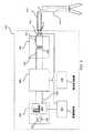
図1は電気外科器具用の電力供給装置を示している。電力供給装置100は、電力供給器102と、LC回路108と、電気出力110とを含み、電力供給装置100は電気外科器具114に接続され、電力を供給するように構成される。電力供給器102は、LC回路108(例えば、直列に接続されたコンデンサ及びインダクタ)に、非正弦波電圧(例えば、パルスDC電圧又は有限スイッチング時間を有する矩形波)を供給することができる。非正弦波電圧は、一定又は実質的に一定(例えば、±50ppm(0.005%))の駆動周波数及び可変振幅を有してもよい。 FIG. 1 shows a power supply for an electrosurgical instrument. The
LC回路108は非正弦波電圧を受電し、その電圧を準正弦波電流に変換する。非正弦波電圧、すなわち駆動電圧は、LC回路108の共振周波数に実質的に1/2で動作する。例示一定駆動周波数は225KHz〜275KHzの範囲を有し、当該範囲内の任意の一定駆動周波数に関して、±50ppmのジッタを含む。このジッタは電子回路(例えば、水晶発振器)に固有のものである。 The
一定駆動周波数は初期に、LC回路108の共振周波数の1/2並びに寄生インダクタンス及び電気容量に調整してもよいが、外科手術ごとには変わらない(更なる調整は可能であるが、必要ではない)。いくつかの実施例においては、LC回路108の共振周波数は通常調整できない(コンデンサ及びインダクタは固定であると仮定し、種々のケーブル112の電気容量及びインダクタンスの変化は無視する)が、パルス発生器106の一定駆動周波数をLC回路108の共振周波数に揃う(例えば、一定駆動周波数が共振周波数の実質的に1/2である)ように調整することができる。LC回路108の共振周波数の実質的に1/2で動作させることによって、LC回路108は、LC回路108が自身の共振周波数又はその近傍で駆動されたとき観察される、無視できるか実質的に無視できるインピーダンスに比べると、LC回路108を通過する電流(準正弦波電流)に対してインピーダンスを示す。 The constant drive frequency may be initially adjusted to 1/2 the
準正弦波電流(例えば、図4〜5の404及び504を参照)は電気出力110に供給される。電気出力110は、ケーブル112を介して電気外科器具114(例えば、バイポーラ器具)に接続され、準正弦波電流を供給するように構成される。準正弦波電流は負荷インピーダンスに応じて変化する。負荷インピーダンスが低い(例えば、6〜25Ω)ときは、準正弦波電流は、サイクルごとに極性反転(flip)(すなわち、180°位相偏移)するLC回路の減衰したリンギングのある出力に似ている。例えば、図4に示された電流404を参照されたい。負荷インピーダンスが(例えば、75〜256Ωに)増加したとき(例えば、電気外科封止の際に血管が加熱されたとき)、準正弦波電流は駆動信号(例えば、パルス波形)に似るようになる。このような高インピーダンスに対する例示準正弦波電流は、図5に見ることができる。 A quasi-sinusoidal current (see, eg, 404 and 504 in FIGS. 4-5) is provided to the
以降、一定駆動周波数と呼ぶが、実質的に一定の駆動周波数も含まれることを理解されたい。含まれる一定駆動周波数の範囲は225〜275KHzであり、目標一定駆動周波数に対して、電子回路は±50ppmの周波数安定度すなわちジッタを有してもよい。以降、周波数の純粋な(absolute)倍数(例えば、2倍、3倍及び4倍)と呼ぶが、当業者であれば、周波数の倍数は、±25KHzの隣接周波数(例えば、一定周波数を250KHzとすると、225〜275KHz)を含むことは明らかである。 Hereinafter, although referred to as a constant drive frequency, it should be understood that a substantially constant drive frequency is also included. The included constant drive frequency range is 225 to 275 KHz, and the electronic circuit may have a frequency stability or jitter of ± 50 ppm relative to the target constant drive frequency. Hereinafter, it is referred to as an absolute multiple of the frequency (for example, 2 times, 3 times, and 4 times). However, those skilled in the art will recognize that the frequency multiple is an adjacent frequency of ± 25 KHz (for example, a constant frequency of 250 KHz). Then, it is clear that 225 to 275 KHz) is included.
一つの実施例においては、電力供給器102は電源104及びDCバス105を介して接続されたパルス発生器106を含む。電源104は、DCバス105を介してパルス発生器106に可変振幅のDC電力(正電流)を供給することができる。電源104はまた、パルス発生器106からDC電力(負電流)を受電することもできる。パルス発生器106は、可変振幅DC電力を受電して、一定駆動周波数を有し、電源104から受電した可変振幅に応じた振幅を有するパルス電圧に変換することができる。 In one embodiment,
電力供給器102及び/又は含まれる電源104は一定電力モードで動作することができる。一定電力とは、電圧及び/又は電流が、所望の又は設定された電力出力を維持(±20%の誤差範囲内に)するために自動的に調整されることを意味する。例えば、負荷インピーダンスが増加して電流が減少すると、電流の減少を相殺するために電力供給器102の電圧出力が増加し、それによって一定電力を維持する。別の例においては、負荷インピーダンスが低下して電流が増加すると、一定電力出力を維持するために電力供給器102の電圧が低下する。このように、5Wに設定された一定電力に対して、一定電力は4〜6Wを含んでもよい。10Wに設定された一定電力に対しては、一定電力は8〜12Wを含んでもよい。15Wに設定された一定電力に対しては、一定電力は12〜18Wを含んでもよい。いくつかの非制限的例を示すとすれば、一定電力は、0〜20W、2〜15W、5〜10W、10〜14W又は5〜12Wを含んでもよい。負荷インピーダンスは主に、例えば電気外科器具の尖叉(tine)の間に挟まれたときの、電気外科器具によって手術されている組織のインピーダンスである。 The
一つの実施例においては、電源104は、電流及び/又は電圧をアップコンバート又はダウンコンバートできる電力変換器(例えば、降圧・昇圧(buck−boost)変換器)を含む。電力変換器は、例えば、電気出力110又はその近傍の電流、電圧、電力及びインピーダンスのうち1又は複数を検出及び分析する帰還ループを介して、制御できる制御可能振幅を有してもよい。電力変換器は、電流の発生及び吸収双方を行うように構成された種類のものであってよい。例えば、電力変換器の1又は複数のコンデンサは、必要なときエネルギを吸収し、後でそのエネルギをLC回路108へ戻すことができる。エネルギを吸収できることによって、LC回路108は蓄積されたエネルギのいくらか又はすべてを周期的に(例えば、準正弦波電流の各パルスの期間中に)放電してDCバス105に還流させ、したがって、蓄積されたエネルギはほとんど乃至まったく累積しない。このことによって、従来の電力供給装置に比べて重大なスパーク及び電流スパイクを深刻でなくすることができる。 In one embodiment,
電流スパイクは、負荷インピーダンスが急速に低下し、LC部品に蓄積されたエネルギが負荷に流れるときに生じる。このような電流スパイクに利用可能なエネルギは、従来、エネルギがLC回路に蓄積されるため望ましいレベルより多かった。さらに、従来のLC回路は共振周波数又はその近傍で駆動され、LC回路はインピーダンスがほとんどないか、無視できるため、電流は急速に上昇することがある。しかしここで、LC回路108のサイクルごとの期間中にエネルギが放電するときは、一つのサイクルで蓄積されたエネルギだけが、回路が短絡した条件下で放電に使われ、したがって、電流スパイク及びスパークは先行技術よりも深刻ではない。このような事象の深刻さは、LC回路108が共振周波数以外(例えば、共振周波数の1/2)で駆動されることによっても軽減される。その結果、LC回路108が駆動信号に対してインピーダンスとして働き、したがって、電流スパイクの際、絶対電流だけでなく電流の変化も制限することになる。 A current spike occurs when the load impedance drops rapidly and the energy stored in the LC component flows to the load. The energy available for such current spikes has traditionally been higher than desired because the energy is stored in the LC circuit. In addition, the current may rise rapidly because conventional LC circuits are driven at or near the resonant frequency and the LC circuit has little or no impedance. Here, however, when energy is discharged during each cycle of the
LC回路にエネルギが蓄積されないことの更なる利点は、電気外科装置に送られる電力をより短時間で切断でき、したがって外科医が手術の終了時をより良く管理できるようになることである。さらに、LC回路に、先行技術より小さなインダクタ及びコンデンサを用いることによっても切断時間が短縮される。 A further advantage of not storing energy in the LC circuit is that the power delivered to the electrosurgical device can be cut off in a shorter time, thus allowing the surgeon to better manage the end of the surgery. Furthermore, the cutting time can be shortened by using smaller inductors and capacitors in the LC circuit than in the prior art.
これに対して、スイッチングがLC回路108の共振周波数で起こったとすると、LC回路108は電流に対して0又は無視できるインピーダンスを呈することになる。その結果、電流スパイク及びスパークはより深刻になり、LC回路108内の実質的にすべてのエネルギを放電してDCバス105に還流することができなくなる。 On the other hand, if switching occurs at the resonant frequency of the
一つの実施例においては、パルス発生器106はhブリッジである。hブリッジは電源104からDC電力を受電し、LC回路108にパルス電圧(例えば、矩形波)を出力することができる。パルス電圧は、LC回路108の特性に基づいた一定駆動周波数(例えば、LC回路108の共振周波数)で供給される。例えば、実質的に一定な駆動周波数は、LC回路108の共振周波数の実質的に1/2に設定してもよい。換言すれば、LC回路108が自己の共振周波数で振動(ring)するように駆動されたとき、駆動パルスはLC回路108の1サイクルおきに極性を反転させてもよい。パルス電力の振幅は、電源104が供給するDC電力の振幅に従う。hブリッジは、電源104が電流を発生及び吸収できるように電流を発生及び吸収でき、LC回路108がサイクルごと1回の期間にエネルギを放電してDCバス105に還流できるようにする。このような期間は駆動電圧の各パルスの第2半期を含んでもよく、準正弦波電流の各周期の第2半期と関連することが望ましい。 In one embodiment, the
エネルギを放電してDCバス105に還流させるために、駆動電圧の極性を、純正弦波電流の零交差点に対して180°位相をずらし、かつ共振周波数の1/2に実質的に等しい周波数で切替えてもよい(低インピーダンスの場合)。このように動作させることによって、LC回路108は電流に対して実質的にインピーダンスを呈し、したがって、電流スパイクに対して上限を呈し、電流スパイク中の電流増加を軽減する。また、エネルギがLC回路108に発生及び累積できるようにする代わりに、共振サイクルごとの1/2期間に、蓄積されたエネルギは放電してDCバス105に還流する。 In order to discharge energy and return it to the
例えば、低負荷インピーダンス(例えば、6〜12Ω)の場合、パルス発生器106からの正負の電圧パルスの第1半期に、エネルギはDCバス105からLC回路108及び電気外科器具114へ流れる。DCバス105は正電流を観測し、駆動電圧と準正弦波電流とは同一の極性を有する。電圧パルスの第2半期に、エネルギはLC回路108からDCバス105へ逆に流れ、エネルギは蓄積されて、その後、次の電圧パルスの第1半期にLC回路108及び電気外科器具114へ再供給される。DCバス105は負電流を観察し、エネルギがDCバス105に戻るときには、駆動電圧と準正弦波電流とは反対の極性を有する。 For example, for a low load impedance (eg, 6-12 Ω), energy flows from the
LC回路108は、直列に接続された誘導性部品(例えばインダクタ)及び電気容量性部品(例えばコンデンサ)を含んでもよい。LC回路108内の誘導性部品及び電気容量性部品の種々の構成を図3に見ることができる。 The
スイッチング損失を減少させるため、LC回路108の電流が実質的に最小のとき、すなわち電流が0アンペアに近づいたときに、パルスを切り替えてもよい。この方法は通常、電流がLC回路108の共振サイクルごとに1回、0アンペアを横切り、LC回路108の共振サイクルごとに1回、0アンペアに近づく、低インピーダンス時に可能である(図4参照)。スイッチングは、零交差点ではなく、準正弦波電流が0アンペアに近づく点又はその近傍で行うことが望ましい。高インピーダンス時には、準正弦波電流は低インピーダンスのときと同様な程度には0アンペアに近づかず(図5参照)、スイッチング損失は避けることがより困難である。 In order to reduce switching losses, the pulses may be switched when the current in the
電圧パルスは有限スイッチング時間を有することがあり、その場合、パルス電圧の位相は、有限スイッチング時間の始め、終わり又は中間のある部分が、LC回路108の準正弦波電流が0アンペアに近づくのと同じ瞬間に起きるように選択される(低インピーダンスの場合)。 The voltage pulse may have a finite switching time, in which case the phase of the pulse voltage is such that the quasi-sinusoidal current of the
LC回路108は、自己の共振周波数の1/2で駆動してもよく、またパルス若しくは矩形波(又はあるほかの非正弦波駆動波形)で駆動してもよい。駆動電圧パルスの位相は、LC回路108の準正弦波電流が0アンペアに近づく瞬間に実質的に起きるようにしてもよい(低インピーダンスのとき)。この独特な駆動周波数及び位相設定は、エネルギを発生及び吸収できる電力供給器102の使用と共に、サイクルごとの一部期間でLC回路108がエネルギを放電して電力供給器102に還流できるようにし、したがってLC回路108に蓄積されるエネルギを減少させることができる。一つの実施例においては、パルス遷移の際に、LC回路108が当該回路に蓄積されている、実質的にすべてのエネルギを放電して電力供給器102に還流する。 The
図2は、電気外科器具に電力を供給する電力供給装置の別の実施例を示している。電力供給装置200は、電源204と、パルス発生器206(例えばhブリッジ)と、LC回路208とを含む。電源204は、発生源222と、電力変換器(例えば降圧・昇圧変換器220)とを含んでもよく、DCバス205を介してパルス発生器206に接続される。LC回路208は、1又は複数の誘導性素子(例えばインダクタ242)と、1又は複数の電気容量性素子(例えばコンデンサ240)と、トランス246とを含んでもよい。電力供給装置200はまた、電気出力210を介してケーブル212に接続されるように構成され、ケーブル212は電気外科器具214(例えばバイポーラ器具)に接続される。電力供給装置200はまた、電気出力210又はその近傍で種々の電気特性(例えば、電圧、電流、電力、インピーダンス)を監視するための1又は複数の感知器250も含んでよい。1又は複数の感知器250は、電源204が発生したDC電力の振幅を制御するか、又は制御するための命令を与えるように構成された帰還制御器260に帰還信号を供給することができる。任意選択の周波数制御器270はパルス発生器206からのパルスの周波数を制御することができ、帰還によって制御してもよいし、メモリ(例えば、半導体メモリ若しくはディスクドライブメモリ)又はユーザ入力によって制御してもよい。 FIG. 2 shows another embodiment of a power supply device for supplying power to an electrosurgical instrument. The
電源204は、発生源222からの電力をアップコンバート及び/又はダウンコンバートできる降圧・昇圧変換器220のような電力変換器を含んでもよい。降圧・昇圧変換器は、可変又は制御可能な振幅を有するDC電力を発生し、振幅は帰還制御器260によって制御される。DC電力の振幅は、電流及び電圧制限のような種々の制限に依存してもよい。電流及び電圧制限は、短絡及び開放の回路異常に対する保護のために設けてもよい。これらの制限は外科医及び患者に対して安全を提供するだけでなく、予期しない電気現象も防ぐ。 The
一つの実施例においては、1又は複数の感知器250は電気出力210又はその近傍の電流及び電圧に関する帰還を行う。帰還制御器260は、測定した電流及び/又は電圧を、電流及び/又は電圧の制限又はしきい値(例えば、最大電圧75ボルト、電流範囲1.3〜1.8アンペア)と比較する。測定した電流又は電圧が制限又はしきい値を超えたときは、帰還制御器260は電源204(又は電源204の降圧・昇圧変換器220)に電流及び/又は電圧を減少させるように指示又は通知してもよい。 In one embodiment, the one or
この減少は予め定めてもよいし(例えば、電流を50%削減)、電流及び/又は電圧の実時間測定値に基づいてもよい。例えば、電流又は電圧のどちらが制限を超えたとしても、電流が制限値以下に低下するまで減少させてもよい。減少率は、1又は複数の感知器250からの電流、電圧、電力及びインピーダンスの実時間測定値に基づいてもよい。例えば、電流又は電圧が一定の割合でしきい値を超えたか、一定の率でしきい値を超えつつあることが観察されたとき、電圧の減少は、電圧又は電流がしきい値を超えたか、電圧又は電流の増加率がそれほど大きくないときよりもより深刻なことがある。 This reduction may be predetermined (eg, 50% reduction in current) or may be based on real time measurements of current and / or voltage. For example, whether the current or voltage exceeds the limit, it may be decreased until the current drops below the limit value. The rate of decrease may be based on real time measurements of current, voltage, power and impedance from one or
また、封止手術の際に組織に印加される所望の電力プロファイル(例えば、対称台形又は非対称台形)に基づいて選択することができる電力プロファイルによって規定された電力制限があってもよい。1又は複数の感知器250は電力を監視し、電力に関する情報を帰還制御器260に提供する。帰還制御器260は、監視した電力と電力プロファイル(例えば、メモリに記憶されている)とを比較して、監視した電力が電力プロファイルを超えているとき、電力を減少するように電源204(又は電源204の降圧・昇圧変換器220)に指示又は通知する。降圧・昇圧変換器220は、帰還制御器260が設定したしきい値又は制限を超えない、可能な限り最大の電力を供給するように、発生源220が供給する最高の電流又は電圧に向かって電力を増加させる傾向を有してもよい。 There may also be a power limit defined by a power profile that can be selected based on a desired power profile (eg, a symmetric trapezoid or an asymmetric trapezoid) applied to the tissue during a sealing operation. One or
しかし、電源204及び電源204の降圧・昇圧変換器220はDCバス205に一定電力を供給することが好ましいことに注意されたい。換言すれば、電源204又は降圧・昇圧変換器220は電流源(一定電流、可変電圧)であるか、電圧源(一定電圧、可変電流)であるよりも、一定電力出力が得られるように可変電流及び可変電圧を有してもよい。本質的に一定電力源であることの利点は、電圧又は電流のいずれかを制御することによって間接的に電力を制御するための帰還回路に関する臨界要求がないことである。このことは制御回路をより高信頼にし、そうでなければ従来の電圧又は電流源に関して起こる可能性がある過渡的なスパイクを除去することができる。 However, it should be noted that the
一つの実施例において、帰還制御器260は、発生源222の出力端子間にインダクタを接続するスイッチ(例えばFET)を制御する。この状態で、インダクタの電流は、電流しきい値に達するまで、時間と共に線形に増加する。電流しきい値は、1又は複数の感知器250からの帰還に基づいてもよい。電流が電流しきい値に達すると、インピーダンスが如何に変化しても、電源204は異なる電流及び電圧を供給しつつ、同一の電力出力を維持するようになるため、電源204は一定電力を供給する。電源204の電流及び電圧は、インピーダンス変化の結果だけでなく、帰還制御器260が制御した一定電力出力の変化にも依存して自動的に変化する。 In one embodiment,
帰還についての臨界要求とは、帰還システムが不安定になる前に、如何に早く帰還システムが運転できるかについて制限があることを意味する(例えば、臨界応答時にシステムが不安定になるまでは、応答が速いほど不安定性が大きくなる)。 Critical requirement for feedback means that there is a limit on how quickly the feedback system can operate before the feedback system becomes unstable (e.g., until the system becomes unstable during critical response, The faster the response, the greater the instability).
電源204及び降圧・昇圧変換器220はまた、電流を発生し、吸収することができる(電流が吸収されるとき、電圧は上昇する)。この特性はすべての電源に共通ではなく、LC回路208がエネルギをDCバス205に還流できるようにすることによって、LC回路208内にエネルギが蓄積しないようにするため、ここで独特な利点を提供するものである。換言すれば、電流を発生及び吸収できない電源は、電力供給装置200では可能な、電流スパイク及びスパークの軽減、又は急速な切断を達成できない。例えば、電源204は、電流を吸収し、LC回路208に吸収した電流を再供給することができるコンデンサバンク(図示していない)を備えた降圧・昇圧変換器を含んでもよい。吸収された電流は、LC回路208の次の共振サイクルにおいて、LC回路208に再供給することができる。 The
パルス発生器206は、パルス又は矩形波のような非正弦波電圧を発生する。また、パルス発生器はhブリッジ又は任意のほかのスイッチモード電力供給装置の形態を取ることができ、パルス又は矩形波信号を発生することができる。hブリッジは、一つの実施例においては4個の電界効果トランジスタ(FET)を有し、その4個のFETは対角線状にオン・オフして、LC回路208に供給される電力の極性を交番するパルス電力又は矩形波を生成する。FETは、損失を最小化又は減少させるように選択される。パルス発生器206は電流を発生及び吸収することができ、電源204のように、独特な電流スパイク及びスパーク防止、及び電力供給装置200の急速切断を可能にする。パルス発生器206は、任意選択の周波数制御器270が指示した一定駆動周波数(例えば、250KHz±25KHz又は500KHz未満の任意の周波数)、かつ振幅が、電源204が供給するDC電力によって制御される可変振幅でパルスを発生する。一つの実施例においては、パルス発生器206は、恐らく±5ppmのジッタを有する、240KHzの一定駆動周波数を発生する。 The
外科手術の際に、一定駆動周波数(パルスの周波数)は一定に保たれるが、電圧パルスの振幅は電源204を介して調整することができる。パルスの振幅の変化はLC回路208(負荷インピーダンスを含む)の準正弦波電流の形状に影響を与え、したがって、電気外科器具214に届けられる平均電力にも影響を与える。このように、電圧パルスの振幅の変化を用いて、外科手術(例えば、血管封止)の際に適用される電力プロファイルを追跡することができる。電源204が供給するDC電流及び電圧は、降圧・昇圧変換器220が(電力プロファイルの与えられた設定ポイントに関して)一定電力を出力するため、負荷インピーダンス(電気外科手術器具214のインピーダンス)が変化したとき、自動的に調整される。 During surgery, the constant drive frequency (pulse frequency) is kept constant, but the amplitude of the voltage pulse can be adjusted via the
スイッチングは本質的にパルス又は矩形波として説明されるが、実際には、「パルス」は台形の形状を有している。換言すれば、あるパルスから次のパルスへのスイッチング時間は有限である。さらに、電力供給装置の回路はほぼ瞬時のスイッチング(又は純粋な矩形波)が可能であるが、この回路の最大性能はいつも利用できるとは限らず、スイッチングは離散的な跳躍ではなく、電圧及び/又は電流のわずかに傾斜した(ramping)上昇・下降を伴うことがある。スイッチング時間は有限であるから、一定駆動周波数は、パルス間の遷移が、実質的に、LC回路208内の準正弦波電流が(低インピーダンスにおいて)0アンペアに近づく時点又はその近傍で起きるように調整することができる。一つの実施例においては、パルス間の遷移は、LC回路208内の準正弦波電流が0アンペアに近づくのと実質的に同時に起きる。 Although switching is essentially described as a pulse or square wave, in practice, a “pulse” has a trapezoidal shape. In other words, the switching time from one pulse to the next is finite. Furthermore, although the power supply circuit is capable of almost instantaneous switching (or pure square wave), the maximum performance of this circuit is not always available, and switching is not a discrete jump, but voltage and It may be accompanied by a slight ramping of the current. Since the switching time is finite, a constant drive frequency is such that the transition between pulses occurs substantially at or near the point where the quasi-sinusoidal current in the
いくつかの実施例においては、任意選択の周波数制御器270は、一定駆動周波数でLC回路208にパルス電圧を供給するように、パルス発生器206に命令又は通知することができる。一定とは、ある組織手術又は血管封止手術の間、LC回路208に届けられるパルスの周波数が一定であることを意味する。別の実施例においては、一定駆動周波数がLC回路208の共振に同調する(例えば、LC回路208の共振周波数の1/2になる)ように、手術の合間に一定駆動周波数を調整してもよい。LC回路208の共振周波数は、LC回路108の誘導性(例えばインダクタ242)及び電気容量性(例えば240)の素子又は部品、並びに(例えば、LC回路208のトランス、及び技術的にはLC回路208の部分ではないケーブル212の)寄生効果に依存する。 In some embodiments, the
帰還機構を有するようには描かれていないが、代替実施例においては、任意選択の周波数制御器270は、LC回路208からLC回路208の電気特性(例えば、電圧、電流、電力、負荷インピーダンス、LC回路インピーダンス、コンデンサ240又はインダクタ242のインピーダンス又はリアクタンス、トランス246及びケーブル212の寄生効果のインピーダンス又はリアクタンス)を指示する帰還信号を受信することができる。 Although not depicted as having a feedback mechanism, in an alternative embodiment, the
LC回路208は、1又は複数の電気容量性素子(例えばコンデンサ240)と、1又は複数の誘導性素子(例えばインダクタ242)と、トランス246と、を含んでもよい。コンデンサ240とインダクタ242とは直列に配置してもよい(この配置の変形は図3に示されている)。トランス246もまた、電気外科器具214と電力供給装置200の残りの部分とを電気絶縁するために、LC回路208の二つの導線又は電線間に配置してもよい。トランス246は1:4の巻数比(1次:2次)を有し、表皮効果を最小にするように選択した直径を有する電線(例えば細心電線)を用いて、磁性体コアの周りに巻かれる。一つの実施例においては、トランス246からの漏えいインダクタンスは、5μHを超えない程度である。 The
コンデンサ240は、LC回路208に蓄積される電荷が少ないように、この容量で用いられる従来のコンデンサより少ない電気容量を有するように選択してもよい。LC回路208に蓄積されるエネルギが低いということは、短絡又は開放の際に、電気外科器具214に放電されるエネルギが少ないことを意味する。蓄積されるエネルギが少ないということは、より大きな誘導性部品及び電気容量性部品を用いた装置よりも迅速に電力を切断できることを意味する。特に、コンデンサ240の例示電気容量値は、制限ではないが、0.01〜1μFを含む。 The
インダクタ242は個別インダクタであってもよい。しかし、パルス発生器206が供給するパルス電圧の一定駆動周波数を決定するとき、LC回路208のインダクタンスは、個別インダクタ242並びにトランス246及びケーブル212、更には電気外科器具214からの寄生インダクタンスを含むように考慮してもよい。換言すれば、パルス発生器206が同調しているLC回路208の共振周波数は、ケーブル212の寄生効果及びLC回路208の外部の器具214の寄生効果さえ考慮に入れる。 The
コンデンサ240は個別部品であってよい。そして、インダクタンスのように、LC回路208の共振周波数を決定するために用いられる電気容量は、コンデンサ240並びにLC回路208の内部及び外部の寄生電気容量にも依存することがある。
一つの実施例においては、誘導性回路は、互いに直列又は並列に接続された2又はそれ以上の誘導性素子を備える。電気容量性回路は、互いに直列又は並列に接続された2又はそれ以上の電気容量性素子を備える。 In one embodiment, the inductive circuit comprises two or more inductive elements connected in series or in parallel with each other. The capacitive circuit includes two or more capacitive elements connected in series or in parallel with each other.
1又は複数の感知器250は、電流及び電圧センサを含んでもよい。また、電力感知器があってもよいし、電流及び電圧感知器からの信号を用いて電力を計算してもよい(例えば、電圧×振幅)。また、LC回路208のインピーダンスだけでなく、負荷インピーダンスを測定するインピーダンス感知器があってもよいし、電流及び電圧感知器によって測定した電流及び電圧に基づいて、これらのインピーダンスを計算してもよい。測定は、出力210又はその近傍で行うことができる。一つの実施例においては、1又は複数の感知器250は、例えばトランス(図示していない)を用いて電気外科器具214から絶縁してもよい。 The one or
一つの実施例においては、ケーブル212、電気外科器具214及び/又は手術を行う組織の変化に適応するように、インダクタ242及びコンデンサ240を(例えば、機械的又は電気的いずれかによって)調整して、LC回路208のインピーダンス及びリアクタンスを変更し、それによって更新周波数を変更することができる。例えば、電力供給装置200に接続されている別の電気外科器具214を扱う(account for)ために、電気的に変更してもよい。 In one embodiment,
この電力供給装置200は、低負荷インピーダンスにおいて、電力供給装置200が高電流を組織に供給し、一方、高負荷インピーダンスにおいては(封止が完了に近づいたとき)高電圧を供給するという望ましい動作を本質的に行うため、有利である。特に、電源204のような一定電源を使用すると、電流源又は電圧源が用いられるときには達成されないこれらの電気特性が本質的に得られる。例えば、一定電力が用いられているため、電流に対する電圧の比はインピーダンスに等しい。したがって、負荷が増加すると電流に対する電圧の比が増加する。 The
図3の(A)〜(F)は、LC回路208内のインダクタ242及びコンデンサ240の配置に関する6個の代替案を示している。これらの構成はそれぞれ、インダクタ及びコンデンサを直列に含むLC回路、すなわち直列LC回路(例えば、LC回路208)の本発明における定義内に入るものである。図示した構成はそれぞれ、図2のLC回路208に置き換えてもよく(図3の(A)は、図2のLC回路208と同一である)、パルス発生器206は図3の左側であり、電気出力210は右側である。 3A to 3F show six alternatives regarding the placement of the
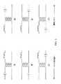
図4は、低負荷インピーダンスに関して、ここで説明したLC回路のうち1又は複数の電流を示している。このような低負荷インピーダンスは、血管封止のような外科手術の開始時及び初期段階で観察されることがある。LC回路は、図1〜2に示した形態(例えば、108、208)であってもよい。LC回路108、208は直列回路であるから、LC回路108、208に入る電流404と、LC回路108、208内部の電流と、LC回路108、208から出る電流は同一である。同様に、パルス発生器(例えば106、206)とLC回路108、208との間の電流404及び電気外科器具(例えば114、214)に供給される電流もまた、図4の電流404によって表される。低インピーダンスは6〜25Ωの負荷インピーダンスを含んでもよいが、それに限定されない。 FIG. 4 shows one or more currents in the LC circuit described herein for low load impedance. Such low load impedance may be observed at the beginning and early stages of surgery such as vascular sealing. The LC circuit may be in the form (for example, 108, 208) shown in FIGS. Since the
パルス発生器106、206からLC回路108、208への駆動電圧402は、ここでは矩形波として示されており(ほかの非正弦波も想定されるが)、LC回路108、208の共振周波数の1/2で切り替えられる。電流404は駆動電圧402と同相であり、電流404のサイクルごと、そして駆動電圧402のサイクルごとに2回、180°位相偏移する。180°位相偏移又は極性反転は、およそ96μs、98μs、100μs、102μs及び104μsで起こる。 The
図4の波形の時間及び電流の値は任意に与えられたものであり、したがって、本発明の範囲を制限する意図はないことに注意されたい。駆動電圧402は任意の電圧で示されており、電流404に対して必ずしも正確な縮尺にはなっていない。 Note that the time and current values of the waveform of FIG. 4 are arbitrarily given and are therefore not intended to limit the scope of the present invention. The
図から分かるように、電流404は、パルス発生器106、206からの駆動電圧402が切り替えられるごとに、180°位相偏移又は極性反転する、振幅抑圧された(dampened)正弦波に似ている。電流404は、97μs、99μs、101μs及び103μsの近傍で0アンペアを横切る。電流は、96μs、98μs、100μs、102μs及び104μs、又はその近傍で0アンペアに近づく。図示したとおり、電流404は駆動電圧402が切り替えられるとき、0アンペアに達しないが、別の実施例においては、使用された回路は、駆動電圧402が切り替えられるとき、電流が0アンペアに達するようになっている。 As can be seen, the current 404 resembles an amplitude-suppressed sine wave that is 180 ° phase shifted or polarity reversed each time the
DCバス(例えば105、205)は、駆動電圧402及び電流404が同一極性のときはいつでも、LC回路108、208及び電気外科器具114、214にエネルギを供給する。例えば、エネルギは、96〜97μs、98〜99μs、100〜101μs、102〜103μs及び104〜105μsの期間に、LC回路108、208及び電気外科器具114、214に供給される。これらの期間中、DCバス105、205内の電流は正である。駆動電圧402と電流404が逆極性を有するときはいつでも、エネルギはDCバス105、205に還流し、LC回路108、208から放電される。例えば、エネルギは、95〜96μs、97〜98μs、99〜100μs、101〜102μs及び103〜104μsの期間にDCバス105、205に還流し、LC回路108、208から放電される。 The DC bus (eg, 105, 205) provides energy to the
このように、DCバス105、205は、パルス発生器106、206からの駆動電圧402のパルスごとの第1半期に電流及び電圧を供給し、駆動電圧402のパルスごとの第2半期に電流及び電圧を吸収する。その結果、パルス切替え又はその近傍において、LC回路108、208内に蓄積された実質的にすべてのエネルギが放電され、DCバス105、205に戻される。したがって、駆動電圧402のパルスの始めでは、LC回路108、208は実質的に蓄積されたエネルギがない。これに対して通常のLC回路では、LC回路サイクルを通じて、インダクタ及びコンデンサが相当量のエネルギを交互に蓄積している。 Thus, the
図5は、高負荷インピーダンスに対する、ここで説明したLC回路のうち1又は複数の電流出力を示している。このような高負荷インピーダンスは、血管封止のような外科手術の終わり近く又は後半に観察されることがある。LC回路は、図1〜2に示した形態(例えば108、208)であってもよい。高インピーダンスは75〜256Ωの負荷インピーダンスを含んでもよいが、それに限定されない。 FIG. 5 shows one or more current outputs of the LC circuit described herein for a high load impedance. Such high load impedance may be observed near or at the end of a surgical procedure such as a vascular seal. The LC circuit may be in the form (for example, 108, 208) shown in FIGS. The high impedance may include, but is not limited to, a load impedance of 75-256Ω.
パルス発生器106、206からLC回路108、208への駆動電圧502は、ここでは矩形波として示されており(ほかの非正弦波波形も想定されるが)、LC回路108、208の共振周波数の1/2で切り替えられる。電流504は駆動電圧502と同相であり、電流504のサイクルごと、そして駆動電圧502のサイクルごとに2回、180°位相偏移する。180°位相偏移又は極性反転は、およそ10μs、12μs、16μs及び18μsで起こる。 The
図5の波形の時間及び電流の値は任意に与えられたものであり、したがって、本発明の範囲を制限する意図はないことに注意されたい。駆動電圧502は任意の電圧で示されており、電流504に対して必ずしも正確な縮尺にはなっていない。 Note that the time and current values of the waveform of FIG. 5 are arbitrarily given and are therefore not intended to limit the scope of the present invention.
低インピーダンスの場合の電流404と異なり、LC回路108、208における振動は十分に抑圧され、図4において見られる電流404の正弦波形状は、図5では見られない。むしろ、電流504は、10μs、12μs、14μs、16μs及び18μs、又はその近傍で切り替えられるパルス駆動電圧502により近い。換言すれば、電流504が0アンペアを横切る点又はその近傍でスイッチングが起きる。また、図4に示した低インピーダンスの状況と異なり、より高いインピーダンスでは、エネルギはDCバス105、205からLC回路108、208及び電気外科器具114、214にだけ供給される。図から分かるように、電流504及び駆動電圧502は常に同一極性であり、したがって、エネルギはDCバス105、205には還流しない。 Unlike the current 404 in the case of low impedance, the oscillations in the
図6は、電気外科器具に電力を供給する方法を示している。方法600は、第1の発生動作602において一定駆動周波数を有する非正弦波駆動電圧を発生する第1のステップを含む。方法600はさらに、第1の供給動作604において、駆動周波数の2倍の共振周波数を有する、LC回路に非正弦波駆動電圧を供給するステップを含む。方法はまた、第2の発生動作606において、非正弦波駆動電圧から準正弦波電流を発生する。最後に方法100は、第2の供給動作608において、電気出力に準正弦波電流を供給する。第2の供給動作608において、電気出力は、外科器具の電気入力に接続するように構成されている。 FIG. 6 illustrates a method for supplying power to an electrosurgical instrument. Method 600 includes a first step of generating a non-sinusoidal drive voltage having a constant drive frequency in a
発生動作602は、例えば電力供給器102(図1参照)又は電源204とパルス発生器206との組合せ(図2参照)によって行われる。非正弦波駆動電圧は矩形波のようなパルス波形であってもよく、波形は、降圧・昇圧変換器220を含んでもよい電源204からDC電力を受電するパルス発生器206のhブリッジを介して整形される。一定駆動周波数は、動作周波数制御器270のような制御器によって制御してもよい。 The
第1の供給動作604は、非正弦波電圧をLC回路(例えば、LC回路108)に供給してもよい。非正弦波駆動電圧は、外科手術に先立って(例えば、製造時又は技術者による調整期間に)LC回路の共振周波数の1/2に等しい周波数(例えば、共振周波数の1/2)に調整してもよい。LC回路をその共振周波数の1/2の周波数で駆動することによって、LC回路は、駆動信号とLC回路を通過する電流とに対して、電流スパイク及びスパークを軽減するインピーダンスを呈する。LC回路をその共振周波数の1/2で駆動することはまた、LC回路が共振サイクルごとに蓄積されたエネルギを放電して、電源(例えば電源204)に戻すようにし、それによって電流スパイク及びスパークに利用される蓄積されたエネルギより少なくする。蓄積されるエネルギレベルがより低いことはまた、外科手術が終わったとき、より速い切断時間を可能にする。また、電流スパイク及びスパークは、LC回路のインピーダンスが電流変化を制限し、電流に上限を設けるため、先行技術に比べてより深刻ではない。 The first supply operation 604 may supply a non-sinusoidal voltage to the LC circuit (eg, the LC circuit 108). The non-sinusoidal drive voltage is adjusted to a frequency (eg, 1/2 of the resonant frequency) equal to 1/2 of the resonant frequency of the LC circuit prior to surgery (eg, during manufacture or during adjustment by a technician). May be. By driving the LC circuit at half its resonant frequency, the LC circuit exhibits an impedance that reduces current spikes and sparks for the drive signal and the current passing through the LC circuit. Driving an LC circuit at half its resonant frequency also causes the LC circuit to discharge stored energy every resonant cycle and return it to a power source (eg, power source 204), thereby causing current spikes and sparks. Less than the stored energy used for The lower stored energy level also allows for faster cutting times when the surgery is over. Also, current spikes and sparks are less severe than the prior art because the impedance of the LC circuit limits the current change and places an upper limit on the current.
共振周波数は、LC回路の個別コンデンサ及び誘導素子の電気容量及びインダクタンス、並びに寄生電気容量及びインダクタンス(例えば、トランス246及びケーブル212)に基づいて決定される。 The resonant frequency is determined based on the capacitance and inductance of the individual capacitors and inductive elements of the LC circuit, and the parasitic capacitance and inductance (eg,
第2の発生動作606は、LC回路の回路208のような回路を用いて、準正弦波電流を発生する。例えば、LC回路208において、パルス電圧が、図4〜5に示した準正弦波電流に変換される。準正弦波電流は、第2の供給動作608において、出力110、210のような電気出力に供給される。電気出力はケーブル(例えばケーブル212)に接続されるように構成し、ケーブルは外科器具(例えば外科器具214)に接続される。 The second generation operation 606 generates a quasi-sinusoidal current using a circuit such as the
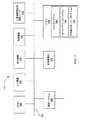
ここで説明したシステム及び方法は、ここで説明した特定の物理的装置に加えて、計算機システムのような機械で実現してもよい。図7は、計算機システム700の例示形態の機械の実施例を表すブロック図であって、当該システムにおいて、本発明の態様及び/又は方法の任意の1又は複数を装置に実行させる命令集合が実行される。計算機システム700はプロセッサ705(又はCPU)及びメモリ740を含み、プロセッサ及びメモリは、バス755を介して互いに、及びほかの構成要素と通信する。例えば、帰還制御器260及び/又は任意選択の周波数制御器270は、プロセッサ705のようなプロセッサを含んでもよい。バス755は、種々のバスアーキテクチャのうち任意のものを用いた、メモリバス、メモリ制御器、周辺機器バス、局所バス及びそれらの任意の組合せを含むが、それに限定されない、いくつかの種類のバス構造のうち任意のものを含んでもよい。 The systems and methods described herein may be implemented on a machine such as a computer system in addition to the specific physical devices described herein. FIG. 7 is a block diagram illustrating an example machine embodiment of a
メモリ740は、ランダムアクセスメモリ構成要素(例えば、スタチックRAM“SRAM”、ダイナミックRAM“DRAM”、EEPROM、等)、リードオンリメモリ、及びそれらの任意の組合せを含むが、それに限定されない種々の構成要素(例えば、機械可読媒体)を含んでもよい。一つの例においては、例えば起動時に計算機システム700内の要素間で情報を転送することを補助する基本ルーチンを含む基本入出力システム742(BIOS)を、メモリ740に記憶させてもよい。メモリ740はまた、本発明の態様及び/又は方法のうち任意の1又は複数を実現する命令又はコード(例えばソフトウェア)を含んで(例えば、1又は複数の機械可読媒体に記憶して)もよい。別の例においては、メモリ740はさらに、オペレーティングシステム744と、1又は複数の応用プログラム746と、ほかのプログラムモジュール746と、プログラムデータ746と、それらの任意の組合せとを含むが、それに限定されない任意の数のプログラムモジュールを含んでもよい。例えばメモリ740は、帰還制御器260(図2参照)のような制御器が、電源204のような電源を制御するために用いる所望の電力プロファイルを記述したデータを記憶してもよい。メモリ740はまた、一定駆動周波数と、電力供給装置20と共に用いられる電気外科器具214の種別に応じた可変振幅との設定を記述したデータを含んでもよい。メモリ740はまた、帰還制御器260が、電圧及び電流スパイクを軽減し、電力が電力プロファイルに従う(track)ことを支援するために用いる、電圧、電流及び電力のしきい値を含んでもよい。 Memory 740 includes various components including, but not limited to, random access memory components (eg, static RAM “SRAM”, dynamic RAM “DRAM”, EEPROM, etc.), read only memory, and any combination thereof. (Eg, a machine-readable medium). In one example, a basic input / output system 742 (BIOS) that includes a basic routine that assists in transferring information between elements in the
計算機システム700はまた記憶装置720も含む。記憶装置(例えば、記憶装置720)の例は、ハードディスクを読み書きするハードディスクドライブと、着脱可能磁気ディスクを読み書きする磁気ディスクドライブと、光媒体(例えばCD、DVD、等)を読み書きする光ディスクドライブと、半導体メモリ装置と、それらの任意の組合せとを含むが、それに限定されない。記憶装置720は、適切なインタフェース(図示していない)によってバス755に接続される。インタフェースの例は、SCSIと、ATAと、シリアルATAと、USBと、IEEE1394と、これらの任意の組合せと、を含むがそれに限定されない。一つの例においては、記憶装置720は計算機システム700と着脱可能に(例えば、外部ポートコネクタ(図示していない)を介して)接続してもよい。例えば、システム700は計算機可読記憶媒体リーダ725を含んでもよく、関連する機械可読媒体(図示していない)は、計算機システム700のための機械可読命令、データ構造、プログラムモジュール及び/又はほかのデータの不揮発性及び/又は揮発性記憶を提供する。一つの例において、ソフトウェア746は機械可読媒体内に全体又は一部があり、計算機可読記憶媒体リーダ725を介して利用することができる。別の例においては、ソフトウェア746はプロセッサ705内に全体又は一部があってもよい。 The
計算機システム700はまた入力装置710も含んでよい。一つの例においては、計算機システム700の利用者は、入力装置710を介して計算機システム700にコマンド及び/又は別の情報を入力してもよい。入力装置710の例は、英数字入力装置(例えばキーボード)と、指示装置と、ジョイスティックと、ゲームパッドと、音響入力装置(例えば、マイクロホン、音声応答システム、等)と、カーソル制御装置(例えばマウス)と、タッチパッドと、光学スキャナと、映像キャプチャ装置(例えば、スチルカメラ、ビデオカメラ)と、タッチスクリーンと、これらの任意の組合せと、を含むが、それに限定されない。入力装置710は、シリアルインタフェースと、パラレルインタフェースと、ゲームポートと、USBインタフェースと、Firewire(登録商標)インタフェースと、バス755への直接インタフェースと、これらの任意の組合せとを含むがそれに限定されない種々のインタフェースのうち任意のものを介して、バス755に接続してもよい。例えば、利用者は入力装置740を介して任意選択の周波数制御器270に一定駆動周波数を入力することができる。 The
利用者はまた、計算機可読記憶媒体リーダ725(例えば、着脱可能ディスクドライブ、フラッシュドライブ、等)及び/又は通信システム730を介して、計算機システム700にコマンド及び/又はほかの情報を入力することができる。通信システム730は、計算機システム700を種々のネットワークのうち1又は複数及び1又は複数の遠隔装置に接続するために用いてもよい。通信システムの例は、ネットワークインタフェースと、モデムと、これらの任意の組合せと、を含むが、これに限定されない。ネットワーク又はネットワークセグメントの例は、広域網(例えば、インターネット、企業内網)と、構内網(例えば、オフィス、ビル、キャンパス又は比較的小さな地理的空間に関係するネットワーク)と、電話網と、二つの計算装置間の直接接続と、これらの任意の組合せと、を含むが、これに限定されない。ネットワークは有線及び/又は無線モードの通信を利用してもよい。一般に、任意のネットワークトポロジを用いてもよい。情報(例えば、データ、ソフトウェア746、等)は、通信システム730を介して計算機システム700へ及び/又は計算機システムから伝送することができる。 A user may also enter commands and / or other information into
計算機システム700はさらに、表示装置のような周辺装置と通信するための出力装置(例えば、ビデオディスプレイアダプタ)を含んでもよい。表示装置の例は、液晶ディスプレイ(LCD)と、陰極線管(CRT)と、プラズマディスプレイと、これらの任意の組合せと、を含むが、これに限定されない。表示装置に加えて、計算機システム700は、スピーカと、プリンタと、これらの任意の組合せとを含むがそれに限定されない1又は複数のほかの出力装置715を含んでもよい。このような出力装置715は、周辺装置インタフェースを介してバス755に接続してもよい。周辺装置インタフェースは、シリアルポートと、USB接続と、Firewire(登録商標)接続と、パラレル接続と、これらの任意の組合せと、を含むがこれに限定されない。一つの例においては、音響装置は、計算機システム700のデータ(例えば、恐らく消費者に起因する汚染の影響及び/又は汚染の相殺に関係する指標を表すデータ)と関係する音響を提供してもよい。 The
必要であれば、手書き入力をデジタル的にキャプチャするためにデジタイザ(図示していない)及び付属するスタイラスを含んでもよい。ペンデジタイザは、表示装置の表示領域とは別個に構成してもよいし、同一領域に構成してもよい。したがって、デジタイザは表示装置と一体であってもよいし、表示装置に被せるか、別様に付加する個別の装置として存在してもよい。 If necessary, a digitizer (not shown) and an associated stylus may be included to digitally capture handwritten input. The pen digitizer may be configured separately from the display area of the display device, or may be configured in the same area. Therefore, the digitizer may be integral with the display device, or may exist as a separate device that covers the display device or is otherwise added.
結論として、本発明はとりわけ、LC回路をその共振周波数の1/2の周波数で駆動し、電気外科器具が使用するためにLC回路から準正弦波電流を供給する、方法、システム及び装置を提供する。準正弦波電流は、先行技術と比べて電流スパイク及びスパークがより深刻ではない。当業者であれば、ここで説明した実施例が達成するのと実質的に同じ結果を達成するために、本発明と、その使用と、構成とに、多くの変形及び代替を行ってもよいことを容易に理解するであろう。したがって、本発明を開示した例示形態に限定する意図はない。多くの変形と、修正物と、代替構成とは、開示した発明の範囲及び精神の中に含まれる。 In conclusion, the present invention provides, among other things, a method, system and apparatus for driving an LC circuit at half its resonant frequency and providing a quasi-sinusoidal current from the LC circuit for use by an electrosurgical instrument. To do. Quasi-sinusoidal currents are less severe in current spikes and sparks than in the prior art. Those skilled in the art may make many variations and alternatives to the invention, its use, and arrangements in order to achieve substantially the same results that the embodiments described herein achieve. You will understand that easily. Accordingly, there is no intention to limit the invention to the disclosed exemplary forms. Many variations, modifications and alternative constructions fall within the scope and spirit of the disclosed invention.
Claims (11)
Translated fromJapanese電力供給装置が、一定の駆動周波数を有する非正弦波駆動電圧を発生させるステップと、
該電力供給装置が、前記一定の駆動周波数の2倍の共振周波数を有する直列LC回路に前記非正弦波駆動電圧を供給するステップと、
該電力供給装置が、前記非正弦波駆動電圧によって前記直列LC回路内に準正弦波電流を発生させるステップと、
該電力供給装置が、電気出力に前記準正弦波電流を供給するステップであって、該電気出力は約75ボルトの最大しきい電圧と約1.8アンペアの最大しきい電流とを有し、該電気出力はバイポーラ組織封止外科器具の電気入力に接続するように構成されている、ステップと、
を有し、
該電気出力及び該組織封止外科器具へ電力を供給している間に負荷インピーダンスが低下するとき、電流が増加するのが許容されるとともに電圧が低下するのが許容され、
前記非正弦波駆動電圧はパルス波形であり、且つ、
前記非正弦波駆動電圧は矩形波であり、
該方法は、該電力供給装置が、前記直列LC回路の共振サイクルごとに1回生じる期間中に、前記直列LC回路に蓄積されているすべてのエネルギを放電するステップ、を更に有する、方法。A method of supplying power to an electrosurgical instrument,
The power supply device generating a non-sinusoidal drive voltage having a constant drive frequency;
The power supply device supplying the non-sinusoidal drive voltage to a series LC circuit having a resonance frequency twice the constant drive frequency;
The power supply generates a quasi-sine wave current in the series LC circuit with the non-sinusoidal drive voltage;
The power supply provides the quasi-sinusoidal current to an electrical output, the electrical output having a maximum threshold voltage of about 75 volts and a maximum threshold current of about 1.8 amps; The electrical output is configured to connect to an electrical input of a bipolar tissue sealing surgical instrument;
Have
When the load impedance decreases while supplying power to the electrical output and the tissue sealing surgical instrument, the current is allowed to increase and the voltage is allowed to drop,
The non-sinusoidal driving voltage is a pulse waveform, and
The non-sinusoidal driving voltage is a rectangular wave,
The method further comprises the step of discharging all energy stored in the series LC circuit during a period that occurs once per resonance cycle of the series LC circuit.
電力供給装置が、一定の駆動周波数を有する非正弦波駆動電圧を発生させるステップと、
該電力供給装置が、前記一定の駆動周波数の2倍の共振周波数を有する直列LC回路に前記非正弦波駆動電圧を供給するステップであって、前記の第1の発生ステップ及び前記供給ステップは電力供給器によって実行される、ステップと、
該電力供給装置が、前記非正弦波駆動電圧から準正弦波電流を発生させるステップと、
該電力供給装置が、エネルギを前記電力供給器に還流させることによって、前記直列LC回路を周期的に放電させるステップと、
該電力供給装置が、電気出力に前記準正弦波電流を供給するステップであって、該電気出力は約75ボルトの最大しきい電圧と約1.8アンペアの最大しきい電流とを有し、該電気出力はバイポーラ組織封止外科器具の電気入力に接続するように構成されている、ステップと、
を有し、該電気出力及び該組織封止外科器具へ電力を供給している間に負荷インピーダンスが低下するとき、電流が増加するのが許容されるとともに電圧が低下するのが許容される、方法。A method of supplying power to an electrosurgical instrument,
The power supply device generating a non-sinusoidal drive voltage having a constant drive frequency;
The power supply device supplying the non-sinusoidal drive voltage to a series LC circuit having a resonance frequency twice the constant drive frequency, wherein the first generation step and the supply step are power Steps performed by the feeder;
Generating a quasi-sine wave current from the non-sinusoidal drive voltage;
The power supply apparatus periodically discharging the series LC circuit by returning energy to the power supply;
The power supply provides the quasi-sinusoidal current to an electrical output, the electrical output having a maximum threshold voltage of about 75 volts and a maximum threshold current of about 1.8 amps; The electrical output is configured to connect to an electrical input of a bipolar tissue sealing surgical instrument;
And when the load impedance decreases while supplying power to the electrical output and the tissue sealing surgical instrument, the current is allowed to increase and the voltage is allowed to decrease. Method.
Applications Claiming Priority (4)
| Application Number | Priority Date | Filing Date | Title |
|---|---|---|---|
| US40576110P | 2010-10-22 | 2010-10-22 | |
| US61/405,761 | 2010-10-22 | ||
| US13/277,979US9039694B2 (en) | 2010-10-22 | 2011-10-20 | RF generator system for surgical vessel sealing |
| US13/277,979 | 2011-10-20 |
Related Parent Applications (1)
| Application Number | Title | Priority Date | Filing Date |
|---|---|---|---|
| JP2015244121ADivisionJP6199949B2 (en) | 2010-10-22 | 2015-12-15 | High frequency generator system for surgical vessel sealing |
Publications (2)
| Publication Number | Publication Date |
|---|---|
| JP2017202385Atrue JP2017202385A (en) | 2017-11-16 |
| JP6571731B2 JP6571731B2 (en) | 2019-09-04 |
Family
ID=45972411
Family Applications (3)
| Application Number | Title | Priority Date | Filing Date |
|---|---|---|---|
| JP2013535106AWithdrawnJP2013543745A (en) | 2010-10-22 | 2011-10-21 | High frequency generator system for surgical vessel sealing |
| JP2015244121AActiveJP6199949B2 (en) | 2010-10-22 | 2015-12-15 | High frequency generator system for surgical vessel sealing |
| JP2017161123AActiveJP6571731B2 (en) | 2010-10-22 | 2017-08-24 | High frequency generator system for surgical vessel sealing |
Family Applications Before (2)
| Application Number | Title | Priority Date | Filing Date |
|---|---|---|---|
| JP2013535106AWithdrawnJP2013543745A (en) | 2010-10-22 | 2011-10-21 | High frequency generator system for surgical vessel sealing |
| JP2015244121AActiveJP6199949B2 (en) | 2010-10-22 | 2015-12-15 | High frequency generator system for surgical vessel sealing |
Country Status (4)
| Country | Link |
|---|---|
| US (4) | US9039694B2 (en) |
| EP (2) | EP3750499B1 (en) |
| JP (3) | JP2013543745A (en) |
| WO (1) | WO2012054791A1 (en) |
Families Citing this family (447)
| Publication number | Priority date | Publication date | Assignee | Title |
|---|---|---|---|---|
| US9060770B2 (en) | 2003-05-20 | 2015-06-23 | Ethicon Endo-Surgery, Inc. | Robotically-driven surgical instrument with E-beam driver |
| US20070084897A1 (en) | 2003-05-20 | 2007-04-19 | Shelton Frederick E Iv | Articulating surgical stapling instrument incorporating a two-piece e-beam firing mechanism |
| US9072535B2 (en) | 2011-05-27 | 2015-07-07 | Ethicon Endo-Surgery, Inc. | Surgical stapling instruments with rotatable staple deployment arrangements |
| US11998198B2 (en) | 2004-07-28 | 2024-06-04 | Cilag Gmbh International | Surgical stapling instrument incorporating a two-piece E-beam firing mechanism |
| US11890012B2 (en) | 2004-07-28 | 2024-02-06 | Cilag Gmbh International | Staple cartridge comprising cartridge body and attached support |
| US8215531B2 (en) | 2004-07-28 | 2012-07-10 | Ethicon Endo-Surgery, Inc. | Surgical stapling instrument having a medical substance dispenser |
| US7934630B2 (en) | 2005-08-31 | 2011-05-03 | Ethicon Endo-Surgery, Inc. | Staple cartridges for forming staples having differing formed staple heights |
| US7669746B2 (en) | 2005-08-31 | 2010-03-02 | Ethicon Endo-Surgery, Inc. | Staple cartridges for forming staples having differing formed staple heights |
| US10159482B2 (en) | 2005-08-31 | 2018-12-25 | Ethicon Llc | Fastener cartridge assembly comprising a fixed anvil and different staple heights |
| US9237891B2 (en) | 2005-08-31 | 2016-01-19 | Ethicon Endo-Surgery, Inc. | Robotically-controlled surgical stapling devices that produce formed staples having different lengths |
| US11246590B2 (en) | 2005-08-31 | 2022-02-15 | Cilag Gmbh International | Staple cartridge including staple drivers having different unfired heights |
| US11484312B2 (en) | 2005-08-31 | 2022-11-01 | Cilag Gmbh International | Staple cartridge comprising a staple driver arrangement |
| US20070106317A1 (en) | 2005-11-09 | 2007-05-10 | Shelton Frederick E Iv | Hydraulically and electrically actuated articulation joints for surgical instruments |
| US20120292367A1 (en) | 2006-01-31 | 2012-11-22 | Ethicon Endo-Surgery, Inc. | Robotically-controlled end effector |
| US8820603B2 (en) | 2006-01-31 | 2014-09-02 | Ethicon Endo-Surgery, Inc. | Accessing data stored in a memory of a surgical instrument |
| US11224427B2 (en) | 2006-01-31 | 2022-01-18 | Cilag Gmbh International | Surgical stapling system including a console and retraction assembly |
| US7845537B2 (en) | 2006-01-31 | 2010-12-07 | Ethicon Endo-Surgery, Inc. | Surgical instrument having recording capabilities |
| US7753904B2 (en) | 2006-01-31 | 2010-07-13 | Ethicon Endo-Surgery, Inc. | Endoscopic surgical instrument with a handle that can articulate with respect to the shaft |
| US11793518B2 (en) | 2006-01-31 | 2023-10-24 | Cilag Gmbh International | Powered surgical instruments with firing system lockout arrangements |
| US8186555B2 (en) | 2006-01-31 | 2012-05-29 | Ethicon Endo-Surgery, Inc. | Motor-driven surgical cutting and fastening instrument with mechanical closure system |
| US20110024477A1 (en) | 2009-02-06 | 2011-02-03 | Hall Steven G | Driven Surgical Stapler Improvements |
| US20110295295A1 (en) | 2006-01-31 | 2011-12-01 | Ethicon Endo-Surgery, Inc. | Robotically-controlled surgical instrument having recording capabilities |
| US11278279B2 (en) | 2006-01-31 | 2022-03-22 | Cilag Gmbh International | Surgical instrument assembly |
| US8708213B2 (en) | 2006-01-31 | 2014-04-29 | Ethicon Endo-Surgery, Inc. | Surgical instrument having a feedback system |
| US8992422B2 (en) | 2006-03-23 | 2015-03-31 | Ethicon Endo-Surgery, Inc. | Robotically-controlled endoscopic accessory channel |
| US8322455B2 (en) | 2006-06-27 | 2012-12-04 | Ethicon Endo-Surgery, Inc. | Manually driven surgical cutting and fastening instrument |
| US10568652B2 (en) | 2006-09-29 | 2020-02-25 | Ethicon Llc | Surgical staples having attached drivers of different heights and stapling instruments for deploying the same |
| US7506791B2 (en) | 2006-09-29 | 2009-03-24 | Ethicon Endo-Surgery, Inc. | Surgical stapling instrument with mechanical mechanism for limiting maximum tissue compression |
| US11980366B2 (en) | 2006-10-03 | 2024-05-14 | Cilag Gmbh International | Surgical instrument |
| US8684253B2 (en) | 2007-01-10 | 2014-04-01 | Ethicon Endo-Surgery, Inc. | Surgical instrument with wireless communication between a control unit of a robotic system and remote sensor |
| US8632535B2 (en) | 2007-01-10 | 2014-01-21 | Ethicon Endo-Surgery, Inc. | Interlock and surgical instrument including same |
| US8652120B2 (en) | 2007-01-10 | 2014-02-18 | Ethicon Endo-Surgery, Inc. | Surgical instrument with wireless communication between control unit and sensor transponders |
| US11291441B2 (en) | 2007-01-10 | 2022-04-05 | Cilag Gmbh International | Surgical instrument with wireless communication between control unit and remote sensor |
| US11039836B2 (en) | 2007-01-11 | 2021-06-22 | Cilag Gmbh International | Staple cartridge for use with a surgical stapling instrument |
| US20080169333A1 (en) | 2007-01-11 | 2008-07-17 | Shelton Frederick E | Surgical stapler end effector with tapered distal end |
| US7673782B2 (en) | 2007-03-15 | 2010-03-09 | Ethicon Endo-Surgery, Inc. | Surgical stapling instrument having a releasable buttress material |
| US8893946B2 (en) | 2007-03-28 | 2014-11-25 | Ethicon Endo-Surgery, Inc. | Laparoscopic tissue thickness and clamp load measuring devices |
| US11564682B2 (en) | 2007-06-04 | 2023-01-31 | Cilag Gmbh International | Surgical stapler device |
| US8931682B2 (en) | 2007-06-04 | 2015-01-13 | Ethicon Endo-Surgery, Inc. | Robotically-controlled shaft based rotary drive systems for surgical instruments |
| US7753245B2 (en) | 2007-06-22 | 2010-07-13 | Ethicon Endo-Surgery, Inc. | Surgical stapling instruments |
| US11849941B2 (en) | 2007-06-29 | 2023-12-26 | Cilag Gmbh International | Staple cartridge having staple cavities extending at a transverse angle relative to a longitudinal cartridge axis |
| US7866527B2 (en) | 2008-02-14 | 2011-01-11 | Ethicon Endo-Surgery, Inc. | Surgical stapling apparatus with interlockable firing system |
| JP5410110B2 (en) | 2008-02-14 | 2014-02-05 | エシコン・エンド−サージェリィ・インコーポレイテッド | Surgical cutting / fixing instrument with RF electrode |
| US7819298B2 (en) | 2008-02-14 | 2010-10-26 | Ethicon Endo-Surgery, Inc. | Surgical stapling apparatus with control features operable with one hand |
| US8758391B2 (en) | 2008-02-14 | 2014-06-24 | Ethicon Endo-Surgery, Inc. | Interchangeable tools for surgical instruments |
| US11986183B2 (en) | 2008-02-14 | 2024-05-21 | Cilag Gmbh International | Surgical cutting and fastening instrument comprising a plurality of sensors to measure an electrical parameter |
| US9179912B2 (en) | 2008-02-14 | 2015-11-10 | Ethicon Endo-Surgery, Inc. | Robotically-controlled motorized surgical cutting and fastening instrument |
| US8573465B2 (en) | 2008-02-14 | 2013-11-05 | Ethicon Endo-Surgery, Inc. | Robotically-controlled surgical end effector system with rotary actuated closure systems |
| US8636736B2 (en) | 2008-02-14 | 2014-01-28 | Ethicon Endo-Surgery, Inc. | Motorized surgical cutting and fastening instrument |
| US11272927B2 (en) | 2008-02-15 | 2022-03-15 | Cilag Gmbh International | Layer arrangements for surgical staple cartridges |
| US9585657B2 (en) | 2008-02-15 | 2017-03-07 | Ethicon Endo-Surgery, Llc | Actuator for releasing a layer of material from a surgical end effector |
| US9005230B2 (en) | 2008-09-23 | 2015-04-14 | Ethicon Endo-Surgery, Inc. | Motorized surgical instrument |
| US11648005B2 (en) | 2008-09-23 | 2023-05-16 | Cilag Gmbh International | Robotically-controlled motorized surgical instrument with an end effector |
| US8210411B2 (en) | 2008-09-23 | 2012-07-03 | Ethicon Endo-Surgery, Inc. | Motor-driven surgical cutting instrument |
| US9386983B2 (en) | 2008-09-23 | 2016-07-12 | Ethicon Endo-Surgery, Llc | Robotically-controlled motorized surgical instrument |
| US8608045B2 (en) | 2008-10-10 | 2013-12-17 | Ethicon Endo-Sugery, Inc. | Powered surgical cutting and stapling apparatus with manually retractable firing system |
| US8517239B2 (en) | 2009-02-05 | 2013-08-27 | Ethicon Endo-Surgery, Inc. | Surgical stapling instrument comprising a magnetic element driver |
| US8444036B2 (en) | 2009-02-06 | 2013-05-21 | Ethicon Endo-Surgery, Inc. | Motor driven surgical fastener device with mechanisms for adjusting a tissue gap within the end effector |
| RU2525225C2 (en) | 2009-02-06 | 2014-08-10 | Этикон Эндо-Серджери, Инк. | Improvement of drive surgical suturing instrument |
| US8220688B2 (en) | 2009-12-24 | 2012-07-17 | Ethicon Endo-Surgery, Inc. | Motor-driven surgical cutting instrument with electric actuator directional control assembly |
| US8851354B2 (en) | 2009-12-24 | 2014-10-07 | Ethicon Endo-Surgery, Inc. | Surgical cutting instrument that analyzes tissue thickness |
| US8783543B2 (en) | 2010-07-30 | 2014-07-22 | Ethicon Endo-Surgery, Inc. | Tissue acquisition arrangements and methods for surgical stapling devices |
| US12213666B2 (en) | 2010-09-30 | 2025-02-04 | Cilag Gmbh International | Tissue thickness compensator comprising layers |
| US11925354B2 (en) | 2010-09-30 | 2024-03-12 | Cilag Gmbh International | Staple cartridge comprising staples positioned within a compressible portion thereof |
| US9016542B2 (en) | 2010-09-30 | 2015-04-28 | Ethicon Endo-Surgery, Inc. | Staple cartridge comprising compressible distortion resistant components |
| US9629814B2 (en) | 2010-09-30 | 2017-04-25 | Ethicon Endo-Surgery, Llc | Tissue thickness compensator configured to redistribute compressive forces |
| US9386988B2 (en) | 2010-09-30 | 2016-07-12 | Ethicon End-Surgery, LLC | Retainer assembly including a tissue thickness compensator |
| US9351730B2 (en) | 2011-04-29 | 2016-05-31 | Ethicon Endo-Surgery, Llc | Tissue thickness compensator comprising channels |
| US10945731B2 (en) | 2010-09-30 | 2021-03-16 | Ethicon Llc | Tissue thickness compensator comprising controlled release and expansion |
| US9232941B2 (en) | 2010-09-30 | 2016-01-12 | Ethicon Endo-Surgery, Inc. | Tissue thickness compensator comprising a reservoir |
| US9788834B2 (en) | 2010-09-30 | 2017-10-17 | Ethicon Llc | Layer comprising deployable attachment members |
| US11812965B2 (en) | 2010-09-30 | 2023-11-14 | Cilag Gmbh International | Layer of material for a surgical end effector |
| US9364233B2 (en) | 2010-09-30 | 2016-06-14 | Ethicon Endo-Surgery, Llc | Tissue thickness compensators for circular surgical staplers |
| US11298125B2 (en) | 2010-09-30 | 2022-04-12 | Cilag Gmbh International | Tissue stapler having a thickness compensator |
| US8695866B2 (en) | 2010-10-01 | 2014-04-15 | Ethicon Endo-Surgery, Inc. | Surgical instrument having a power control circuit |
| US9039694B2 (en)* | 2010-10-22 | 2015-05-26 | Just Right Surgical, Llc | RF generator system for surgical vessel sealing |
| AU2012250197B2 (en) | 2011-04-29 | 2017-08-10 | Ethicon Endo-Surgery, Inc. | Staple cartridge comprising staples positioned within a compressible portion thereof |
| US11207064B2 (en) | 2011-05-27 | 2021-12-28 | Cilag Gmbh International | Automated end effector component reloading system for use with a robotic system |
| US9044230B2 (en) | 2012-02-13 | 2015-06-02 | Ethicon Endo-Surgery, Inc. | Surgical cutting and fastening instrument with apparatus for determining cartridge and firing motion status |
| BR112014024098B1 (en) | 2012-03-28 | 2021-05-25 | Ethicon Endo-Surgery, Inc. | staple cartridge |
| JP6224070B2 (en) | 2012-03-28 | 2017-11-01 | エシコン・エンド−サージェリィ・インコーポレイテッドEthicon Endo−Surgery,Inc. | Retainer assembly including tissue thickness compensator |
| MX358135B (en) | 2012-03-28 | 2018-08-06 | Ethicon Endo Surgery Inc | Tissue thickness compensator comprising a plurality of layers. |
| US9101358B2 (en) | 2012-06-15 | 2015-08-11 | Ethicon Endo-Surgery, Inc. | Articulatable surgical instrument comprising a firing drive |
| BR112014032776B1 (en) | 2012-06-28 | 2021-09-08 | Ethicon Endo-Surgery, Inc | SURGICAL INSTRUMENT SYSTEM AND SURGICAL KIT FOR USE WITH A SURGICAL INSTRUMENT SYSTEM |
| US9408606B2 (en) | 2012-06-28 | 2016-08-09 | Ethicon Endo-Surgery, Llc | Robotically powered surgical device with manually-actuatable reversing system |
| JP6290201B2 (en) | 2012-06-28 | 2018-03-07 | エシコン・エンド−サージェリィ・インコーポレイテッドEthicon Endo−Surgery,Inc. | Lockout for empty clip cartridge |
| US11278284B2 (en) | 2012-06-28 | 2022-03-22 | Cilag Gmbh International | Rotary drive arrangements for surgical instruments |
| US20140005718A1 (en) | 2012-06-28 | 2014-01-02 | Ethicon Endo-Surgery, Inc. | Multi-functional powered surgical device with external dissection features |
| US9289256B2 (en) | 2012-06-28 | 2016-03-22 | Ethicon Endo-Surgery, Llc | Surgical end effectors having angled tissue-contacting surfaces |
| US9282974B2 (en) | 2012-06-28 | 2016-03-15 | Ethicon Endo-Surgery, Llc | Empty clip cartridge lockout |
| US20140001231A1 (en) | 2012-06-28 | 2014-01-02 | Ethicon Endo-Surgery, Inc. | Firing system lockout arrangements for surgical instruments |
| US12383267B2 (en) | 2012-06-28 | 2025-08-12 | Cilag Gmbh International | Robotically powered surgical device with manually-actuatable reversing system |
| JP6200167B2 (en)* | 2013-02-27 | 2017-09-20 | デクセリアルズ株式会社 | Power receiving device, received power adjusting method, received power adjusting program, and semiconductor device |
| RU2672520C2 (en) | 2013-03-01 | 2018-11-15 | Этикон Эндо-Серджери, Инк. | Hingedly turnable surgical instruments with conducting ways for signal transfer |
| BR112015021082B1 (en) | 2013-03-01 | 2022-05-10 | Ethicon Endo-Surgery, Inc | surgical instrument |
| US9629629B2 (en) | 2013-03-14 | 2017-04-25 | Ethicon Endo-Surgey, LLC | Control systems for surgical instruments |
| US9808244B2 (en) | 2013-03-14 | 2017-11-07 | Ethicon Llc | Sensor arrangements for absolute positioning system for surgical instruments |
| BR112015026109B1 (en) | 2013-04-16 | 2022-02-22 | Ethicon Endo-Surgery, Inc | surgical instrument |
| US9826976B2 (en) | 2013-04-16 | 2017-11-28 | Ethicon Llc | Motor driven surgical instruments with lockable dual drive shafts |
| US9775609B2 (en) | 2013-08-23 | 2017-10-03 | Ethicon Llc | Tamper proof circuit for surgical instrument battery pack |
| MX369362B (en) | 2013-08-23 | 2019-11-06 | Ethicon Endo Surgery Llc | Firing member retraction devices for powered surgical instruments. |
| US10188446B2 (en)* | 2013-10-16 | 2019-01-29 | Covidien Lp | Resonant inverter |
| GB201321710D0 (en)* | 2013-12-09 | 2014-01-22 | Creo Medical Ltd | Electrosurgical apparatus |
| US9962161B2 (en) | 2014-02-12 | 2018-05-08 | Ethicon Llc | Deliverable surgical instrument |
| JP6462004B2 (en) | 2014-02-24 | 2019-01-30 | エシコン エルエルシー | Fastening system with launcher lockout |
| US10013049B2 (en) | 2014-03-26 | 2018-07-03 | Ethicon Llc | Power management through sleep options of segmented circuit and wake up control |
| BR112016021943B1 (en) | 2014-03-26 | 2022-06-14 | Ethicon Endo-Surgery, Llc | SURGICAL INSTRUMENT FOR USE BY AN OPERATOR IN A SURGICAL PROCEDURE |
| US12232723B2 (en) | 2014-03-26 | 2025-02-25 | Cilag Gmbh International | Systems and methods for controlling a segmented circuit |
| US10004497B2 (en) | 2014-03-26 | 2018-06-26 | Ethicon Llc | Interface systems for use with surgical instruments |
| US20150272580A1 (en) | 2014-03-26 | 2015-10-01 | Ethicon Endo-Surgery, Inc. | Verification of number of battery exchanges/procedure count |
| DK3122414T3 (en) | 2014-03-26 | 2021-05-31 | Venclose Inc | Cable unit |
| US20150272655A1 (en)* | 2014-03-27 | 2015-10-01 | Medtronic Ablation Frontiers, Llc | Controlled rf energy in a multi-electrode catheter |
| BR112016023825B1 (en) | 2014-04-16 | 2022-08-02 | Ethicon Endo-Surgery, Llc | STAPLE CARTRIDGE FOR USE WITH A SURGICAL STAPLER AND STAPLE CARTRIDGE FOR USE WITH A SURGICAL INSTRUMENT |
| US20150297225A1 (en) | 2014-04-16 | 2015-10-22 | Ethicon Endo-Surgery, Inc. | Fastener cartridges including extensions having different configurations |
| CN106456159B (en) | 2014-04-16 | 2019-03-08 | 伊西康内外科有限责任公司 | Fastener Cartridge Assembly and Nail Retainer Cover Arrangement |
| US10470768B2 (en) | 2014-04-16 | 2019-11-12 | Ethicon Llc | Fastener cartridge including a layer attached thereto |
| US10327764B2 (en) | 2014-09-26 | 2019-06-25 | Ethicon Llc | Method for creating a flexible staple line |
| CN106456176B (en) | 2014-04-16 | 2019-06-28 | 伊西康内外科有限责任公司 | Fastener Cartridge Including Extensions With Different Configurations |
| US11311294B2 (en) | 2014-09-05 | 2022-04-26 | Cilag Gmbh International | Powered medical device including measurement of closure state of jaws |
| US10135242B2 (en) | 2014-09-05 | 2018-11-20 | Ethicon Llc | Smart cartridge wake up operation and data retention |
| BR112017004361B1 (en) | 2014-09-05 | 2023-04-11 | Ethicon Llc | ELECTRONIC SYSTEM FOR A SURGICAL INSTRUMENT |
| US10105142B2 (en) | 2014-09-18 | 2018-10-23 | Ethicon Llc | Surgical stapler with plurality of cutting elements |
| CN107427300B (en) | 2014-09-26 | 2020-12-04 | 伊西康有限责任公司 | Surgical suture buttresses and auxiliary materials |
| US11523821B2 (en) | 2014-09-26 | 2022-12-13 | Cilag Gmbh International | Method for creating a flexible staple line |
| US10076325B2 (en) | 2014-10-13 | 2018-09-18 | Ethicon Llc | Surgical stapling apparatus comprising a tissue stop |
| US9924944B2 (en) | 2014-10-16 | 2018-03-27 | Ethicon Llc | Staple cartridge comprising an adjunct material |
| US10517594B2 (en) | 2014-10-29 | 2019-12-31 | Ethicon Llc | Cartridge assemblies for surgical staplers |
| US11141153B2 (en) | 2014-10-29 | 2021-10-12 | Cilag Gmbh International | Staple cartridges comprising driver arrangements |
| US9844376B2 (en) | 2014-11-06 | 2017-12-19 | Ethicon Llc | Staple cartridge comprising a releasable adjunct material |
| US10736636B2 (en) | 2014-12-10 | 2020-08-11 | Ethicon Llc | Articulatable surgical instrument system |
| US10085748B2 (en) | 2014-12-18 | 2018-10-02 | Ethicon Llc | Locking arrangements for detachable shaft assemblies with articulatable surgical end effectors |
| US10188385B2 (en) | 2014-12-18 | 2019-01-29 | Ethicon Llc | Surgical instrument system comprising lockable systems |
| US9987000B2 (en) | 2014-12-18 | 2018-06-05 | Ethicon Llc | Surgical instrument assembly comprising a flexible articulation system |
| US9844375B2 (en) | 2014-12-18 | 2017-12-19 | Ethicon Llc | Drive arrangements for articulatable surgical instruments |
| MX389118B (en) | 2014-12-18 | 2025-03-20 | Ethicon Llc | SURGICAL INSTRUMENT WITH AN ANVIL THAT CAN BE SELECTIVELY MOVED ON A DISCRETE, NON-MOBILE AXIS RELATIVE TO A STAPLE CARTRIDGE. |
| US9943309B2 (en) | 2014-12-18 | 2018-04-17 | Ethicon Llc | Surgical instruments with articulatable end effectors and movable firing beam support arrangements |
| US9844374B2 (en) | 2014-12-18 | 2017-12-19 | Ethicon Llc | Surgical instrument systems comprising an articulatable end effector and means for adjusting the firing stroke of a firing member |
| NO341430B1 (en)* | 2015-01-19 | 2017-11-13 | Waertsilae Norway As | An apparatus and a method for wireless transmission of power between DC voltage sources |
| US11154301B2 (en) | 2015-02-27 | 2021-10-26 | Cilag Gmbh International | Modular stapling assembly |
| US10180463B2 (en) | 2015-02-27 | 2019-01-15 | Ethicon Llc | Surgical apparatus configured to assess whether a performance parameter of the surgical apparatus is within an acceptable performance band |
| US10159483B2 (en) | 2015-02-27 | 2018-12-25 | Ethicon Llc | Surgical apparatus configured to track an end-of-life parameter |
| JP2020121162A (en) | 2015-03-06 | 2020-08-13 | エシコン エルエルシーEthicon LLC | Time dependent evaluation of sensor data to determine stability element, creep element and viscoelastic element of measurement |
| US10548504B2 (en) | 2015-03-06 | 2020-02-04 | Ethicon Llc | Overlaid multi sensor radio frequency (RF) electrode system to measure tissue compression |
| US9808246B2 (en) | 2015-03-06 | 2017-11-07 | Ethicon Endo-Surgery, Llc | Method of operating a powered surgical instrument |
| US9924961B2 (en) | 2015-03-06 | 2018-03-27 | Ethicon Endo-Surgery, Llc | Interactive feedback system for powered surgical instruments |
| US9993248B2 (en) | 2015-03-06 | 2018-06-12 | Ethicon Endo-Surgery, Llc | Smart sensors with local signal processing |
| DE102015204127A1 (en)* | 2015-03-06 | 2016-09-08 | Olympus Winter & Ibe Gmbh | Electrosurgery generator |
| US10441279B2 (en) | 2015-03-06 | 2019-10-15 | Ethicon Llc | Multiple level thresholds to modify operation of powered surgical instruments |
| US10687806B2 (en) | 2015-03-06 | 2020-06-23 | Ethicon Llc | Adaptive tissue compression techniques to adjust closure rates for multiple tissue types |
| US9901342B2 (en) | 2015-03-06 | 2018-02-27 | Ethicon Endo-Surgery, Llc | Signal and power communication system positioned on a rotatable shaft |
| US10245033B2 (en) | 2015-03-06 | 2019-04-02 | Ethicon Llc | Surgical instrument comprising a lockable battery housing |
| US10617412B2 (en) | 2015-03-06 | 2020-04-14 | Ethicon Llc | System for detecting the mis-insertion of a staple cartridge into a surgical stapler |
| US10433844B2 (en) | 2015-03-31 | 2019-10-08 | Ethicon Llc | Surgical instrument with selectively disengageable threaded drive systems |
| US10835249B2 (en) | 2015-08-17 | 2020-11-17 | Ethicon Llc | Implantable layers for a surgical instrument |
| US10327769B2 (en) | 2015-09-23 | 2019-06-25 | Ethicon Llc | Surgical stapler having motor control based on a drive system component |
| US10105139B2 (en) | 2015-09-23 | 2018-10-23 | Ethicon Llc | Surgical stapler having downstream current-based motor control |
| US10363036B2 (en) | 2015-09-23 | 2019-07-30 | Ethicon Llc | Surgical stapler having force-based motor control |
| US10076326B2 (en)* | 2015-09-23 | 2018-09-18 | Ethicon Llc | Surgical stapler having current mirror-based motor control |
| US10238386B2 (en) | 2015-09-23 | 2019-03-26 | Ethicon Llc | Surgical stapler having motor control based on an electrical parameter related to a motor current |
| US10299878B2 (en) | 2015-09-25 | 2019-05-28 | Ethicon Llc | Implantable adjunct systems for determining adjunct skew |
| US10478188B2 (en) | 2015-09-30 | 2019-11-19 | Ethicon Llc | Implantable layer comprising a constricted configuration |
| US10433846B2 (en) | 2015-09-30 | 2019-10-08 | Ethicon Llc | Compressible adjunct with crossing spacer fibers |
| US11890015B2 (en) | 2015-09-30 | 2024-02-06 | Cilag Gmbh International | Compressible adjunct with crossing spacer fibers |
| US10980539B2 (en) | 2015-09-30 | 2021-04-20 | Ethicon Llc | Implantable adjunct comprising bonded layers |
| CN108472007B (en)* | 2015-11-02 | 2023-06-09 | 皇家飞利浦有限公司 | Active distribution of high voltage power for ultrasonic transducers |
| US10292704B2 (en) | 2015-12-30 | 2019-05-21 | Ethicon Llc | Mechanisms for compensating for battery pack failure in powered surgical instruments |
| US10368865B2 (en) | 2015-12-30 | 2019-08-06 | Ethicon Llc | Mechanisms for compensating for drivetrain failure in powered surgical instruments |
| US10265068B2 (en) | 2015-12-30 | 2019-04-23 | Ethicon Llc | Surgical instruments with separable motors and motor control circuits |
| MX372938B (en) | 2016-01-13 | 2020-04-03 | Koninklijke Philips Nv | WIRELESS INDUCTIVE POWER TRANSFER. |
| US11213293B2 (en) | 2016-02-09 | 2022-01-04 | Cilag Gmbh International | Articulatable surgical instruments with single articulation link arrangements |
| BR112018016098B1 (en) | 2016-02-09 | 2023-02-23 | Ethicon Llc | SURGICAL INSTRUMENT |
| US10413291B2 (en) | 2016-02-09 | 2019-09-17 | Ethicon Llc | Surgical instrument articulation mechanism with slotted secondary constraint |
| US10448948B2 (en) | 2016-02-12 | 2019-10-22 | Ethicon Llc | Mechanisms for compensating for drivetrain failure in powered surgical instruments |
| US10258331B2 (en) | 2016-02-12 | 2019-04-16 | Ethicon Llc | Mechanisms for compensating for drivetrain failure in powered surgical instruments |
| US11224426B2 (en) | 2016-02-12 | 2022-01-18 | Cilag Gmbh International | Mechanisms for compensating for drivetrain failure in powered surgical instruments |
| US10617413B2 (en) | 2016-04-01 | 2020-04-14 | Ethicon Llc | Closure system arrangements for surgical cutting and stapling devices with separate and distinct firing shafts |
| US10413297B2 (en) | 2016-04-01 | 2019-09-17 | Ethicon Llc | Surgical stapling system configured to apply annular rows of staples having different heights |
| US10765471B2 (en) | 2016-04-15 | 2020-09-08 | Bolder Surgical, Llc | Electrosurgical sealer and divider |
| WO2017181092A1 (en) | 2016-04-15 | 2017-10-19 | Just Right Surgical, Llc | Electrosurgical sealer and divider |
| US10492783B2 (en) | 2016-04-15 | 2019-12-03 | Ethicon, Llc | Surgical instrument with improved stop/start control during a firing motion |
| US10357247B2 (en) | 2016-04-15 | 2019-07-23 | Ethicon Llc | Surgical instrument with multiple program responses during a firing motion |
| US11607239B2 (en) | 2016-04-15 | 2023-03-21 | Cilag Gmbh International | Systems and methods for controlling a surgical stapling and cutting instrument |
| US10335145B2 (en) | 2016-04-15 | 2019-07-02 | Ethicon Llc | Modular surgical instrument with configurable operating mode |
| US10426467B2 (en) | 2016-04-15 | 2019-10-01 | Ethicon Llc | Surgical instrument with detection sensors |
| US10405859B2 (en) | 2016-04-15 | 2019-09-10 | Ethicon Llc | Surgical instrument with adjustable stop/start control during a firing motion |
| US10828028B2 (en) | 2016-04-15 | 2020-11-10 | Ethicon Llc | Surgical instrument with multiple program responses during a firing motion |
| US11179150B2 (en) | 2016-04-15 | 2021-11-23 | Cilag Gmbh International | Systems and methods for controlling a surgical stapling and cutting instrument |
| US10456137B2 (en) | 2016-04-15 | 2019-10-29 | Ethicon Llc | Staple formation detection mechanisms |
| US10363037B2 (en) | 2016-04-18 | 2019-07-30 | Ethicon Llc | Surgical instrument system comprising a magnetic lockout |
| US11317917B2 (en) | 2016-04-18 | 2022-05-03 | Cilag Gmbh International | Surgical stapling system comprising a lockable firing assembly |
| US20170296173A1 (en) | 2016-04-18 | 2017-10-19 | Ethicon Endo-Surgery, Llc | Method for operating a surgical instrument |
| US10500000B2 (en) | 2016-08-16 | 2019-12-10 | Ethicon Llc | Surgical tool with manual control of end effector jaws |
| JP6634989B2 (en)* | 2016-09-21 | 2020-01-22 | 京セラドキュメントソリューションズ株式会社 | Image forming device |
| EP3884895B1 (en)* | 2016-11-29 | 2022-10-05 | St. Jude Medical, Cardiology Division, Inc. | Electroporation systems and catheters for electroporation systems |
| US10813638B2 (en) | 2016-12-21 | 2020-10-27 | Ethicon Llc | Surgical end effectors with expandable tissue stop arrangements |
| US10485543B2 (en) | 2016-12-21 | 2019-11-26 | Ethicon Llc | Anvil having a knife slot width |
| JP6983893B2 (en) | 2016-12-21 | 2021-12-17 | エシコン エルエルシーEthicon LLC | Lockout configuration for surgical end effectors and replaceable tool assemblies |
| US11090048B2 (en) | 2016-12-21 | 2021-08-17 | Cilag Gmbh International | Method for resetting a fuse of a surgical instrument shaft |
| JP2020501815A (en) | 2016-12-21 | 2020-01-23 | エシコン エルエルシーEthicon LLC | Surgical stapling system |
| US10542982B2 (en) | 2016-12-21 | 2020-01-28 | Ethicon Llc | Shaft assembly comprising first and second articulation lockouts |
| JP7010956B2 (en) | 2016-12-21 | 2022-01-26 | エシコン エルエルシー | How to staple tissue |
| US10426471B2 (en) | 2016-12-21 | 2019-10-01 | Ethicon Llc | Surgical instrument with multiple failure response modes |
| US11419606B2 (en) | 2016-12-21 | 2022-08-23 | Cilag Gmbh International | Shaft assembly comprising a clutch configured to adapt the output of a rotary firing member to two different systems |
| MX2019007295A (en) | 2016-12-21 | 2019-10-15 | Ethicon Llc | Surgical instrument system comprising an end effector lockout and a firing assembly lockout. |
| US10898186B2 (en) | 2016-12-21 | 2021-01-26 | Ethicon Llc | Staple forming pocket arrangements comprising primary sidewalls and pocket sidewalls |
| US10758229B2 (en) | 2016-12-21 | 2020-09-01 | Ethicon Llc | Surgical instrument comprising improved jaw control |
| US20180168625A1 (en) | 2016-12-21 | 2018-06-21 | Ethicon Endo-Surgery, Llc | Surgical stapling instruments with smart staple cartridges |
| US11134942B2 (en) | 2016-12-21 | 2021-10-05 | Cilag Gmbh International | Surgical stapling instruments and staple-forming anvils |
| US10980536B2 (en) | 2016-12-21 | 2021-04-20 | Ethicon Llc | No-cartridge and spent cartridge lockout arrangements for surgical staplers |
| US20180168615A1 (en) | 2016-12-21 | 2018-06-21 | Ethicon Endo-Surgery, Llc | Method of deforming staples from two different types of staple cartridges with the same surgical stapling instrument |
| CN110087565A (en) | 2016-12-21 | 2019-08-02 | 爱惜康有限责任公司 | Surgical stapling system |
| US10568625B2 (en) | 2016-12-21 | 2020-02-25 | Ethicon Llc | Staple cartridges and arrangements of staples and staple cavities therein |
| US10582928B2 (en) | 2016-12-21 | 2020-03-10 | Ethicon Llc | Articulation lock arrangements for locking an end effector in an articulated position in response to actuation of a jaw closure system |
| JP7010957B2 (en) | 2016-12-21 | 2022-01-26 | エシコン エルエルシー | Shaft assembly with lockout |
| US10973516B2 (en) | 2016-12-21 | 2021-04-13 | Ethicon Llc | Surgical end effectors and adaptable firing members therefor |
| US10695055B2 (en) | 2016-12-21 | 2020-06-30 | Ethicon Llc | Firing assembly comprising a lockout |
| US10368864B2 (en) | 2017-06-20 | 2019-08-06 | Ethicon Llc | Systems and methods for controlling displaying motor velocity for a surgical instrument |
| US10779820B2 (en) | 2017-06-20 | 2020-09-22 | Ethicon Llc | Systems and methods for controlling motor speed according to user input for a surgical instrument |
| US10980537B2 (en) | 2017-06-20 | 2021-04-20 | Ethicon Llc | Closed loop feedback control of motor velocity of a surgical stapling and cutting instrument based on measured time over a specified number of shaft rotations |
| USD879809S1 (en) | 2017-06-20 | 2020-03-31 | Ethicon Llc | Display panel with changeable graphical user interface |
| USD890784S1 (en) | 2017-06-20 | 2020-07-21 | Ethicon Llc | Display panel with changeable graphical user interface |
| US10307170B2 (en) | 2017-06-20 | 2019-06-04 | Ethicon Llc | Method for closed loop control of motor velocity of a surgical stapling and cutting instrument |
| US10390841B2 (en) | 2017-06-20 | 2019-08-27 | Ethicon Llc | Control of motor velocity of a surgical stapling and cutting instrument based on angle of articulation |
| US11090046B2 (en) | 2017-06-20 | 2021-08-17 | Cilag Gmbh International | Systems and methods for controlling displacement member motion of a surgical stapling and cutting instrument |
| US11382638B2 (en) | 2017-06-20 | 2022-07-12 | Cilag Gmbh International | Closed loop feedback control of motor velocity of a surgical stapling and cutting instrument based on measured time over a specified displacement distance |
| US11071554B2 (en) | 2017-06-20 | 2021-07-27 | Cilag Gmbh International | Closed loop feedback control of motor velocity of a surgical stapling and cutting instrument based on magnitude of velocity error measurements |
| US10881396B2 (en) | 2017-06-20 | 2021-01-05 | Ethicon Llc | Surgical instrument with variable duration trigger arrangement |
| US11517325B2 (en) | 2017-06-20 | 2022-12-06 | Cilag Gmbh International | Closed loop feedback control of motor velocity of a surgical stapling and cutting instrument based on measured displacement distance traveled over a specified time interval |
| US11653914B2 (en) | 2017-06-20 | 2023-05-23 | Cilag Gmbh International | Systems and methods for controlling motor velocity of a surgical stapling and cutting instrument according to articulation angle of end effector |
| US10881399B2 (en) | 2017-06-20 | 2021-01-05 | Ethicon Llc | Techniques for adaptive control of motor velocity of a surgical stapling and cutting instrument |
| US10624633B2 (en) | 2017-06-20 | 2020-04-21 | Ethicon Llc | Systems and methods for controlling motor velocity of a surgical stapling and cutting instrument |
| US10813639B2 (en) | 2017-06-20 | 2020-10-27 | Ethicon Llc | Closed loop feedback control of motor velocity of a surgical stapling and cutting instrument based on system conditions |
| USD879808S1 (en) | 2017-06-20 | 2020-03-31 | Ethicon Llc | Display panel with graphical user interface |
| US10646220B2 (en) | 2017-06-20 | 2020-05-12 | Ethicon Llc | Systems and methods for controlling displacement member velocity for a surgical instrument |
| US10888321B2 (en) | 2017-06-20 | 2021-01-12 | Ethicon Llc | Systems and methods for controlling velocity of a displacement member of a surgical stapling and cutting instrument |
| US10327767B2 (en) | 2017-06-20 | 2019-06-25 | Ethicon Llc | Control of motor velocity of a surgical stapling and cutting instrument based on angle of articulation |
| US10856869B2 (en) | 2017-06-27 | 2020-12-08 | Ethicon Llc | Surgical anvil arrangements |
| US11266405B2 (en) | 2017-06-27 | 2022-03-08 | Cilag Gmbh International | Surgical anvil manufacturing methods |
| US10993716B2 (en) | 2017-06-27 | 2021-05-04 | Ethicon Llc | Surgical anvil arrangements |
| US10772629B2 (en) | 2017-06-27 | 2020-09-15 | Ethicon Llc | Surgical anvil arrangements |
| US11090049B2 (en) | 2017-06-27 | 2021-08-17 | Cilag Gmbh International | Staple forming pocket arrangements |
| US11324503B2 (en) | 2017-06-27 | 2022-05-10 | Cilag Gmbh International | Surgical firing member arrangements |
| US11564686B2 (en) | 2017-06-28 | 2023-01-31 | Cilag Gmbh International | Surgical shaft assemblies with flexible interfaces |
| USD854151S1 (en) | 2017-06-28 | 2019-07-16 | Ethicon Llc | Surgical instrument shaft |
| US10903685B2 (en) | 2017-06-28 | 2021-01-26 | Ethicon Llc | Surgical shaft assemblies with slip ring assemblies forming capacitive channels |
| USD851762S1 (en) | 2017-06-28 | 2019-06-18 | Ethicon Llc | Anvil |
| USD906355S1 (en) | 2017-06-28 | 2020-12-29 | Ethicon Llc | Display screen or portion thereof with a graphical user interface for a surgical instrument |
| US10211586B2 (en) | 2017-06-28 | 2019-02-19 | Ethicon Llc | Surgical shaft assemblies with watertight housings |
| US10716614B2 (en) | 2017-06-28 | 2020-07-21 | Ethicon Llc | Surgical shaft assemblies with slip ring assemblies with increased contact pressure |
| US11259805B2 (en) | 2017-06-28 | 2022-03-01 | Cilag Gmbh International | Surgical instrument comprising firing member supports |
| EP3420947B1 (en) | 2017-06-28 | 2022-05-25 | Cilag GmbH International | Surgical instrument comprising selectively actuatable rotatable couplers |
| USD869655S1 (en) | 2017-06-28 | 2019-12-10 | Ethicon Llc | Surgical fastener cartridge |
| US10758232B2 (en) | 2017-06-28 | 2020-09-01 | Ethicon Llc | Surgical instrument with positive jaw opening features |
| US11484310B2 (en) | 2017-06-28 | 2022-11-01 | Cilag Gmbh International | Surgical instrument comprising a shaft including a closure tube profile |
| US10765427B2 (en) | 2017-06-28 | 2020-09-08 | Ethicon Llc | Method for articulating a surgical instrument |
| US11246592B2 (en) | 2017-06-28 | 2022-02-15 | Cilag Gmbh International | Surgical instrument comprising an articulation system lockable to a frame |
| US10258418B2 (en) | 2017-06-29 | 2019-04-16 | Ethicon Llc | System for controlling articulation forces |
| US10398434B2 (en) | 2017-06-29 | 2019-09-03 | Ethicon Llc | Closed loop velocity control of closure member for robotic surgical instrument |
| US10898183B2 (en) | 2017-06-29 | 2021-01-26 | Ethicon Llc | Robotic surgical instrument with closed loop feedback techniques for advancement of closure member during firing |
| US11007022B2 (en) | 2017-06-29 | 2021-05-18 | Ethicon Llc | Closed loop velocity control techniques based on sensed tissue parameters for robotic surgical instrument |
| US10932772B2 (en) | 2017-06-29 | 2021-03-02 | Ethicon Llc | Methods for closed loop velocity control for robotic surgical instrument |
| US11304695B2 (en) | 2017-08-03 | 2022-04-19 | Cilag Gmbh International | Surgical system shaft interconnection |
| US11471155B2 (en) | 2017-08-03 | 2022-10-18 | Cilag Gmbh International | Surgical system bailout |
| US11974742B2 (en) | 2017-08-03 | 2024-05-07 | Cilag Gmbh International | Surgical system comprising an articulation bailout |
| US11944300B2 (en) | 2017-08-03 | 2024-04-02 | Cilag Gmbh International | Method for operating a surgical system bailout |
| DE102017215598A1 (en)* | 2017-09-05 | 2019-03-07 | Siemens Mobility GmbH | Converter arrangement |
| US10743872B2 (en) | 2017-09-29 | 2020-08-18 | Ethicon Llc | System and methods for controlling a display of a surgical instrument |
| US10765429B2 (en) | 2017-09-29 | 2020-09-08 | Ethicon Llc | Systems and methods for providing alerts according to the operational state of a surgical instrument |
| US10796471B2 (en) | 2017-09-29 | 2020-10-06 | Ethicon Llc | Systems and methods of displaying a knife position for a surgical instrument |
| USD917500S1 (en) | 2017-09-29 | 2021-04-27 | Ethicon Llc | Display screen or portion thereof with graphical user interface |
| US11399829B2 (en) | 2017-09-29 | 2022-08-02 | Cilag Gmbh International | Systems and methods of initiating a power shutdown mode for a surgical instrument |
| US10729501B2 (en) | 2017-09-29 | 2020-08-04 | Ethicon Llc | Systems and methods for language selection of a surgical instrument |
| USD907647S1 (en) | 2017-09-29 | 2021-01-12 | Ethicon Llc | Display screen or portion thereof with animated graphical user interface |
| USD907648S1 (en) | 2017-09-29 | 2021-01-12 | Ethicon Llc | Display screen or portion thereof with animated graphical user interface |
| US11134944B2 (en) | 2017-10-30 | 2021-10-05 | Cilag Gmbh International | Surgical stapler knife motion controls |
| US11090075B2 (en) | 2017-10-30 | 2021-08-17 | Cilag Gmbh International | Articulation features for surgical end effector |
| US10842490B2 (en) | 2017-10-31 | 2020-11-24 | Ethicon Llc | Cartridge body design with force reduction based on firing completion |
| US10779903B2 (en) | 2017-10-31 | 2020-09-22 | Ethicon Llc | Positive shaft rotation lock activated by jaw closure |
| US11006955B2 (en) | 2017-12-15 | 2021-05-18 | Ethicon Llc | End effectors with positive jaw opening features for use with adapters for electromechanical surgical instruments |
| US11197670B2 (en) | 2017-12-15 | 2021-12-14 | Cilag Gmbh International | Surgical end effectors with pivotal jaws configured to touch at their respective distal ends when fully closed |
| US10869666B2 (en) | 2017-12-15 | 2020-12-22 | Ethicon Llc | Adapters with control systems for controlling multiple motors of an electromechanical surgical instrument |
| US10779826B2 (en) | 2017-12-15 | 2020-09-22 | Ethicon Llc | Methods of operating surgical end effectors |
| US10828033B2 (en) | 2017-12-15 | 2020-11-10 | Ethicon Llc | Handheld electromechanical surgical instruments with improved motor control arrangements for positioning components of an adapter coupled thereto |
| US10966718B2 (en) | 2017-12-15 | 2021-04-06 | Ethicon Llc | Dynamic clamping assemblies with improved wear characteristics for use in connection with electromechanical surgical instruments |
| US10687813B2 (en) | 2017-12-15 | 2020-06-23 | Ethicon Llc | Adapters with firing stroke sensing arrangements for use in connection with electromechanical surgical instruments |
| US10743875B2 (en) | 2017-12-15 | 2020-08-18 | Ethicon Llc | Surgical end effectors with jaw stiffener arrangements configured to permit monitoring of firing member |
| US11033267B2 (en) | 2017-12-15 | 2021-06-15 | Ethicon Llc | Systems and methods of controlling a clamping member firing rate of a surgical instrument |
| US10779825B2 (en) | 2017-12-15 | 2020-09-22 | Ethicon Llc | Adapters with end effector position sensing and control arrangements for use in connection with electromechanical surgical instruments |
| US11071543B2 (en) | 2017-12-15 | 2021-07-27 | Cilag Gmbh International | Surgical end effectors with clamping assemblies configured to increase jaw aperture ranges |
| US10743874B2 (en) | 2017-12-15 | 2020-08-18 | Ethicon Llc | Sealed adapters for use with electromechanical surgical instruments |
| US11020112B2 (en) | 2017-12-19 | 2021-06-01 | Ethicon Llc | Surgical tools configured for interchangeable use with different controller interfaces |
| US10716565B2 (en) | 2017-12-19 | 2020-07-21 | Ethicon Llc | Surgical instruments with dual articulation drivers |
| US11045270B2 (en) | 2017-12-19 | 2021-06-29 | Cilag Gmbh International | Robotic attachment comprising exterior drive actuator |
| US10835330B2 (en) | 2017-12-19 | 2020-11-17 | Ethicon Llc | Method for determining the position of a rotatable jaw of a surgical instrument attachment assembly |
| US10729509B2 (en) | 2017-12-19 | 2020-08-04 | Ethicon Llc | Surgical instrument comprising closure and firing locking mechanism |
| USD910847S1 (en) | 2017-12-19 | 2021-02-16 | Ethicon Llc | Surgical instrument assembly |
| US11311290B2 (en) | 2017-12-21 | 2022-04-26 | Cilag Gmbh International | Surgical instrument comprising an end effector dampener |
| US11076853B2 (en) | 2017-12-21 | 2021-08-03 | Cilag Gmbh International | Systems and methods of displaying a knife position during transection for a surgical instrument |
| US11179151B2 (en) | 2017-12-21 | 2021-11-23 | Cilag Gmbh International | Surgical instrument comprising a display |
| US12336705B2 (en) | 2017-12-21 | 2025-06-24 | Cilag Gmbh International | Continuous use self-propelled stapling instrument |
| US11129680B2 (en) | 2017-12-21 | 2021-09-28 | Cilag Gmbh International | Surgical instrument comprising a projector |
| US11039834B2 (en) | 2018-08-20 | 2021-06-22 | Cilag Gmbh International | Surgical stapler anvils with staple directing protrusions and tissue stability features |
| US11324501B2 (en) | 2018-08-20 | 2022-05-10 | Cilag Gmbh International | Surgical stapling devices with improved closure members |
| US11045192B2 (en) | 2018-08-20 | 2021-06-29 | Cilag Gmbh International | Fabricating techniques for surgical stapler anvils |
| US20200054321A1 (en) | 2018-08-20 | 2020-02-20 | Ethicon Llc | Surgical instruments with progressive jaw closure arrangements |
| US10779821B2 (en) | 2018-08-20 | 2020-09-22 | Ethicon Llc | Surgical stapler anvils with tissue stop features configured to avoid tissue pinch |
| US10912559B2 (en) | 2018-08-20 | 2021-02-09 | Ethicon Llc | Reinforced deformable anvil tip for surgical stapler anvil |
| US11207065B2 (en) | 2018-08-20 | 2021-12-28 | Cilag Gmbh International | Method for fabricating surgical stapler anvils |
| US10856870B2 (en) | 2018-08-20 | 2020-12-08 | Ethicon Llc | Switching arrangements for motor powered articulatable surgical instruments |
| US11083458B2 (en) | 2018-08-20 | 2021-08-10 | Cilag Gmbh International | Powered surgical instruments with clutching arrangements to convert linear drive motions to rotary drive motions |
| USD914878S1 (en) | 2018-08-20 | 2021-03-30 | Ethicon Llc | Surgical instrument anvil |
| US10842492B2 (en) | 2018-08-20 | 2020-11-24 | Ethicon Llc | Powered articulatable surgical instruments with clutching and locking arrangements for linking an articulation drive system to a firing drive system |
| US11291440B2 (en) | 2018-08-20 | 2022-04-05 | Cilag Gmbh International | Method for operating a powered articulatable surgical instrument |
| US11253256B2 (en) | 2018-08-20 | 2022-02-22 | Cilag Gmbh International | Articulatable motor powered surgical instruments with dedicated articulation motor arrangements |
| USD904611S1 (en) | 2018-10-10 | 2020-12-08 | Bolder Surgical, Llc | Jaw design for a surgical instrument |
| US11172929B2 (en) | 2019-03-25 | 2021-11-16 | Cilag Gmbh International | Articulation drive arrangements for surgical systems |
| US11147553B2 (en) | 2019-03-25 | 2021-10-19 | Cilag Gmbh International | Firing drive arrangements for surgical systems |
| US11696761B2 (en) | 2019-03-25 | 2023-07-11 | Cilag Gmbh International | Firing drive arrangements for surgical systems |
| US11147551B2 (en) | 2019-03-25 | 2021-10-19 | Cilag Gmbh International | Firing drive arrangements for surgical systems |
| US11253254B2 (en) | 2019-04-30 | 2022-02-22 | Cilag Gmbh International | Shaft rotation actuator on a surgical instrument |
| US11903581B2 (en) | 2019-04-30 | 2024-02-20 | Cilag Gmbh International | Methods for stapling tissue using a surgical instrument |
| US11452528B2 (en) | 2019-04-30 | 2022-09-27 | Cilag Gmbh International | Articulation actuators for a surgical instrument |
| US11471157B2 (en) | 2019-04-30 | 2022-10-18 | Cilag Gmbh International | Articulation control mapping for a surgical instrument |
| US11426251B2 (en) | 2019-04-30 | 2022-08-30 | Cilag Gmbh International | Articulation directional lights on a surgical instrument |
| US11648009B2 (en) | 2019-04-30 | 2023-05-16 | Cilag Gmbh International | Rotatable jaw tip for a surgical instrument |
| US11432816B2 (en) | 2019-04-30 | 2022-09-06 | Cilag Gmbh International | Articulation pin for a surgical instrument |
| US11771419B2 (en) | 2019-06-28 | 2023-10-03 | Cilag Gmbh International | Packaging for a replaceable component of a surgical stapling system |
| US11246678B2 (en) | 2019-06-28 | 2022-02-15 | Cilag Gmbh International | Surgical stapling system having a frangible RFID tag |
| US11638587B2 (en) | 2019-06-28 | 2023-05-02 | Cilag Gmbh International | RFID identification systems for surgical instruments |
| US11426167B2 (en) | 2019-06-28 | 2022-08-30 | Cilag Gmbh International | Mechanisms for proper anvil attachment surgical stapling head assembly |
| US11291451B2 (en) | 2019-06-28 | 2022-04-05 | Cilag Gmbh International | Surgical instrument with battery compatibility verification functionality |
| US12004740B2 (en) | 2019-06-28 | 2024-06-11 | Cilag Gmbh International | Surgical stapling system having an information decryption protocol |
| US11478241B2 (en) | 2019-06-28 | 2022-10-25 | Cilag Gmbh International | Staple cartridge including projections |
| US11241235B2 (en) | 2019-06-28 | 2022-02-08 | Cilag Gmbh International | Method of using multiple RFID chips with a surgical assembly |
| US11376098B2 (en) | 2019-06-28 | 2022-07-05 | Cilag Gmbh International | Surgical instrument system comprising an RFID system |
| US11464601B2 (en) | 2019-06-28 | 2022-10-11 | Cilag Gmbh International | Surgical instrument comprising an RFID system for tracking a movable component |
| US11298132B2 (en) | 2019-06-28 | 2022-04-12 | Cilag GmbH Inlernational | Staple cartridge including a honeycomb extension |
| US11259803B2 (en) | 2019-06-28 | 2022-03-01 | Cilag Gmbh International | Surgical stapling system having an information encryption protocol |
| US11219455B2 (en) | 2019-06-28 | 2022-01-11 | Cilag Gmbh International | Surgical instrument including a lockout key |
| US11660163B2 (en) | 2019-06-28 | 2023-05-30 | Cilag Gmbh International | Surgical system with RFID tags for updating motor assembly parameters |
| US11684434B2 (en) | 2019-06-28 | 2023-06-27 | Cilag Gmbh International | Surgical RFID assemblies for instrument operational setting control |
| US11497492B2 (en) | 2019-06-28 | 2022-11-15 | Cilag Gmbh International | Surgical instrument including an articulation lock |
| US11627959B2 (en) | 2019-06-28 | 2023-04-18 | Cilag Gmbh International | Surgical instruments including manual and powered system lockouts |
| US11298127B2 (en) | 2019-06-28 | 2022-04-12 | Cilag GmbH Interational | Surgical stapling system having a lockout mechanism for an incompatible cartridge |
| US11553971B2 (en) | 2019-06-28 | 2023-01-17 | Cilag Gmbh International | Surgical RFID assemblies for display and communication |
| US11051807B2 (en) | 2019-06-28 | 2021-07-06 | Cilag Gmbh International | Packaging assembly including a particulate trap |
| US11224497B2 (en) | 2019-06-28 | 2022-01-18 | Cilag Gmbh International | Surgical systems with multiple RFID tags |
| US11523822B2 (en) | 2019-06-28 | 2022-12-13 | Cilag Gmbh International | Battery pack including a circuit interrupter |
| US11399837B2 (en) | 2019-06-28 | 2022-08-02 | Cilag Gmbh International | Mechanisms for motor control adjustments of a motorized surgical instrument |
| US11529186B2 (en) | 2019-07-22 | 2022-12-20 | Covidien Lp | Electrosurgical forceps including thermal cutting element |
| US11559304B2 (en) | 2019-12-19 | 2023-01-24 | Cilag Gmbh International | Surgical instrument comprising a rapid closure mechanism |
| US11464512B2 (en) | 2019-12-19 | 2022-10-11 | Cilag Gmbh International | Staple cartridge comprising a curved deck surface |
| US11234698B2 (en) | 2019-12-19 | 2022-02-01 | Cilag Gmbh International | Stapling system comprising a clamp lockout and a firing lockout |
| US11504122B2 (en) | 2019-12-19 | 2022-11-22 | Cilag Gmbh International | Surgical instrument comprising a nested firing member |
| US11911032B2 (en) | 2019-12-19 | 2024-02-27 | Cilag Gmbh International | Staple cartridge comprising a seating cam |
| US11607219B2 (en) | 2019-12-19 | 2023-03-21 | Cilag Gmbh International | Staple cartridge comprising a detachable tissue cutting knife |
| US11529139B2 (en) | 2019-12-19 | 2022-12-20 | Cilag Gmbh International | Motor driven surgical instrument |
| US11446029B2 (en) | 2019-12-19 | 2022-09-20 | Cilag Gmbh International | Staple cartridge comprising projections extending from a curved deck surface |
| US11701111B2 (en) | 2019-12-19 | 2023-07-18 | Cilag Gmbh International | Method for operating a surgical stapling instrument |
| US11529137B2 (en) | 2019-12-19 | 2022-12-20 | Cilag Gmbh International | Staple cartridge comprising driver retention members |
| US11931033B2 (en) | 2019-12-19 | 2024-03-19 | Cilag Gmbh International | Staple cartridge comprising a latch lockout |
| US11844520B2 (en) | 2019-12-19 | 2023-12-19 | Cilag Gmbh International | Staple cartridge comprising driver retention members |
| US11576672B2 (en) | 2019-12-19 | 2023-02-14 | Cilag Gmbh International | Surgical instrument comprising a closure system including a closure member and an opening member driven by a drive screw |
| US11304696B2 (en) | 2019-12-19 | 2022-04-19 | Cilag Gmbh International | Surgical instrument comprising a powered articulation system |
| US11291447B2 (en) | 2019-12-19 | 2022-04-05 | Cilag Gmbh International | Stapling instrument comprising independent jaw closing and staple firing systems |
| US12035913B2 (en) | 2019-12-19 | 2024-07-16 | Cilag Gmbh International | Staple cartridge comprising a deployable knife |
| US12049706B2 (en) | 2019-12-21 | 2024-07-30 | Covidien Lp | Thermal cutting elements, electrosurgical instruments including thermal cutting elements, and methods of manufacturing |
| US11159124B2 (en)* | 2020-03-09 | 2021-10-26 | Biosense Webster (Israel) Ltd. | Sine-wave generation using pulsed D-class amplifier |
| US12408970B2 (en) | 2020-04-02 | 2025-09-09 | Covidien Lp | Systems and methods for sealing and dissecting tissue using an electrosurgical forceps including a thermal cutting element |
| USD974560S1 (en) | 2020-06-02 | 2023-01-03 | Cilag Gmbh International | Staple cartridge |
| USD966512S1 (en) | 2020-06-02 | 2022-10-11 | Cilag Gmbh International | Staple cartridge |
| USD976401S1 (en) | 2020-06-02 | 2023-01-24 | Cilag Gmbh International | Staple cartridge |
| USD975850S1 (en) | 2020-06-02 | 2023-01-17 | Cilag Gmbh International | Staple cartridge |
| USD975851S1 (en) | 2020-06-02 | 2023-01-17 | Cilag Gmbh International | Staple cartridge |
| USD975278S1 (en) | 2020-06-02 | 2023-01-10 | Cilag Gmbh International | Staple cartridge |
| USD967421S1 (en) | 2020-06-02 | 2022-10-18 | Cilag Gmbh International | Staple cartridge |
| US11871925B2 (en) | 2020-07-28 | 2024-01-16 | Cilag Gmbh International | Surgical instruments with dual spherical articulation joint arrangements |
| US11638819B2 (en)* | 2020-09-11 | 2023-05-02 | Galvanize Therapeutics, Inc. | Signal generators for use with tissue modification systems |
| USD1013170S1 (en) | 2020-10-29 | 2024-01-30 | Cilag Gmbh International | Surgical instrument assembly |
| US11717289B2 (en) | 2020-10-29 | 2023-08-08 | Cilag Gmbh International | Surgical instrument comprising an indicator which indicates that an articulation drive is actuatable |
| US12053175B2 (en) | 2020-10-29 | 2024-08-06 | Cilag Gmbh International | Surgical instrument comprising a stowed closure actuator stop |
| US11452526B2 (en) | 2020-10-29 | 2022-09-27 | Cilag Gmbh International | Surgical instrument comprising a staged voltage regulation start-up system |
| US11617577B2 (en) | 2020-10-29 | 2023-04-04 | Cilag Gmbh International | Surgical instrument comprising a sensor configured to sense whether an articulation drive of the surgical instrument is actuatable |
| USD980425S1 (en) | 2020-10-29 | 2023-03-07 | Cilag Gmbh International | Surgical instrument assembly |
| US11896217B2 (en) | 2020-10-29 | 2024-02-13 | Cilag Gmbh International | Surgical instrument comprising an articulation lock |
| US11517390B2 (en) | 2020-10-29 | 2022-12-06 | Cilag Gmbh International | Surgical instrument comprising a limited travel switch |
| US11534259B2 (en) | 2020-10-29 | 2022-12-27 | Cilag Gmbh International | Surgical instrument comprising an articulation indicator |
| US11931025B2 (en) | 2020-10-29 | 2024-03-19 | Cilag Gmbh International | Surgical instrument comprising a releasable closure drive lock |
| US11844518B2 (en) | 2020-10-29 | 2023-12-19 | Cilag Gmbh International | Method for operating a surgical instrument |
| US11779330B2 (en) | 2020-10-29 | 2023-10-10 | Cilag Gmbh International | Surgical instrument comprising a jaw alignment system |
| US11678882B2 (en) | 2020-12-02 | 2023-06-20 | Cilag Gmbh International | Surgical instruments with interactive features to remedy incidental sled movements |
| US11944296B2 (en) | 2020-12-02 | 2024-04-02 | Cilag Gmbh International | Powered surgical instruments with external connectors |
| US11627960B2 (en) | 2020-12-02 | 2023-04-18 | Cilag Gmbh International | Powered surgical instruments with smart reload with separately attachable exteriorly mounted wiring connections |
| US11849943B2 (en) | 2020-12-02 | 2023-12-26 | Cilag Gmbh International | Surgical instrument with cartridge release mechanisms |
| US11653920B2 (en) | 2020-12-02 | 2023-05-23 | Cilag Gmbh International | Powered surgical instruments with communication interfaces through sterile barrier |
| US11653915B2 (en) | 2020-12-02 | 2023-05-23 | Cilag Gmbh International | Surgical instruments with sled location detection and adjustment features |
| US11737751B2 (en) | 2020-12-02 | 2023-08-29 | Cilag Gmbh International | Devices and methods of managing energy dissipated within sterile barriers of surgical instrument housings |
| US11890010B2 (en) | 2020-12-02 | 2024-02-06 | Cllag GmbH International | Dual-sided reinforced reload for surgical instruments |
| US11744581B2 (en) | 2020-12-02 | 2023-09-05 | Cilag Gmbh International | Powered surgical instruments with multi-phase tissue treatment |
| CA3204986A1 (en) | 2021-02-01 | 2022-08-04 | Bolder Surgical, Llc | E-cut sealer-divider |
| US12048472B2 (en) | 2021-02-01 | 2024-07-30 | Covidien Lp | Electrosurgical instruments, jaw members thereof, and methods of manufacturing |
| US12108951B2 (en) | 2021-02-26 | 2024-10-08 | Cilag Gmbh International | Staple cartridge comprising a sensing array and a temperature control system |
| US11925349B2 (en) | 2021-02-26 | 2024-03-12 | Cilag Gmbh International | Adjustment to transfer parameters to improve available power |
| US11751869B2 (en) | 2021-02-26 | 2023-09-12 | Cilag Gmbh International | Monitoring of multiple sensors over time to detect moving characteristics of tissue |
| US11950779B2 (en) | 2021-02-26 | 2024-04-09 | Cilag Gmbh International | Method of powering and communicating with a staple cartridge |
| US11730473B2 (en) | 2021-02-26 | 2023-08-22 | Cilag Gmbh International | Monitoring of manufacturing life-cycle |
| US11701113B2 (en) | 2021-02-26 | 2023-07-18 | Cilag Gmbh International | Stapling instrument comprising a separate power antenna and a data transfer antenna |
| US11812964B2 (en) | 2021-02-26 | 2023-11-14 | Cilag Gmbh International | Staple cartridge comprising a power management circuit |
| US11744583B2 (en) | 2021-02-26 | 2023-09-05 | Cilag Gmbh International | Distal communication array to tune frequency of RF systems |
| US12324580B2 (en) | 2021-02-26 | 2025-06-10 | Cilag Gmbh International | Method of powering and communicating with a staple cartridge |
| US11950777B2 (en) | 2021-02-26 | 2024-04-09 | Cilag Gmbh International | Staple cartridge comprising an information access control system |
| US11696757B2 (en) | 2021-02-26 | 2023-07-11 | Cilag Gmbh International | Monitoring of internal systems to detect and track cartridge motion status |
| US11723657B2 (en) | 2021-02-26 | 2023-08-15 | Cilag Gmbh International | Adjustable communication based on available bandwidth and power capacity |
| US11793514B2 (en) | 2021-02-26 | 2023-10-24 | Cilag Gmbh International | Staple cartridge comprising sensor array which may be embedded in cartridge body |
| US11749877B2 (en) | 2021-02-26 | 2023-09-05 | Cilag Gmbh International | Stapling instrument comprising a signal antenna |
| US11980362B2 (en) | 2021-02-26 | 2024-05-14 | Cilag Gmbh International | Surgical instrument system comprising a power transfer coil |
| US11759202B2 (en) | 2021-03-22 | 2023-09-19 | Cilag Gmbh International | Staple cartridge comprising an implantable layer |
| US11826042B2 (en) | 2021-03-22 | 2023-11-28 | Cilag Gmbh International | Surgical instrument comprising a firing drive including a selectable leverage mechanism |
| US11826012B2 (en) | 2021-03-22 | 2023-11-28 | Cilag Gmbh International | Stapling instrument comprising a pulsed motor-driven firing rack |
| US11737749B2 (en) | 2021-03-22 | 2023-08-29 | Cilag Gmbh International | Surgical stapling instrument comprising a retraction system |
| US11723658B2 (en) | 2021-03-22 | 2023-08-15 | Cilag Gmbh International | Staple cartridge comprising a firing lockout |
| US11717291B2 (en) | 2021-03-22 | 2023-08-08 | Cilag Gmbh International | Staple cartridge comprising staples configured to apply different tissue compression |
| US11806011B2 (en) | 2021-03-22 | 2023-11-07 | Cilag Gmbh International | Stapling instrument comprising tissue compression systems |
| US11793516B2 (en) | 2021-03-24 | 2023-10-24 | Cilag Gmbh International | Surgical staple cartridge comprising longitudinal support beam |
| US11896219B2 (en) | 2021-03-24 | 2024-02-13 | Cilag Gmbh International | Mating features between drivers and underside of a cartridge deck |
| US11903582B2 (en) | 2021-03-24 | 2024-02-20 | Cilag Gmbh International | Leveraging surfaces for cartridge installation |
| US11849944B2 (en) | 2021-03-24 | 2023-12-26 | Cilag Gmbh International | Drivers for fastener cartridge assemblies having rotary drive screws |
| US11832816B2 (en) | 2021-03-24 | 2023-12-05 | Cilag Gmbh International | Surgical stapling assembly comprising nonplanar staples and planar staples |
| US11786239B2 (en) | 2021-03-24 | 2023-10-17 | Cilag Gmbh International | Surgical instrument articulation joint arrangements comprising multiple moving linkage features |
| US11786243B2 (en) | 2021-03-24 | 2023-10-17 | Cilag Gmbh International | Firing members having flexible portions for adapting to a load during a surgical firing stroke |
| US11849945B2 (en) | 2021-03-24 | 2023-12-26 | Cilag Gmbh International | Rotary-driven surgical stapling assembly comprising eccentrically driven firing member |
| US11896218B2 (en) | 2021-03-24 | 2024-02-13 | Cilag Gmbh International | Method of using a powered stapling device |
| US11944336B2 (en) | 2021-03-24 | 2024-04-02 | Cilag Gmbh International | Joint arrangements for multi-planar alignment and support of operational drive shafts in articulatable surgical instruments |
| US11744603B2 (en) | 2021-03-24 | 2023-09-05 | Cilag Gmbh International | Multi-axis pivot joints for surgical instruments and methods for manufacturing same |
| US11857183B2 (en) | 2021-03-24 | 2024-01-02 | Cilag Gmbh International | Stapling assembly components having metal substrates and plastic bodies |
| US12102323B2 (en) | 2021-03-24 | 2024-10-01 | Cilag Gmbh International | Rotary-driven surgical stapling assembly comprising a floatable component |
| EP4329644A1 (en) | 2021-04-28 | 2024-03-06 | Bolder Surgical, LLC | Sealer - divider - dissector and related methods |
| US12251155B2 (en) | 2021-05-27 | 2025-03-18 | Covidien Lp | Methods for open dissection using sealing instrument |
| US11826047B2 (en) | 2021-05-28 | 2023-11-28 | Cilag Gmbh International | Stapling instrument comprising jaw mounts |
| US11957337B2 (en) | 2021-10-18 | 2024-04-16 | Cilag Gmbh International | Surgical stapling assembly with offset ramped drive surfaces |
| US11980363B2 (en) | 2021-10-18 | 2024-05-14 | Cilag Gmbh International | Row-to-row staple array variations |
| US12239317B2 (en) | 2021-10-18 | 2025-03-04 | Cilag Gmbh International | Anvil comprising an arrangement of forming pockets proximal to tissue stop |
| US11877745B2 (en) | 2021-10-18 | 2024-01-23 | Cilag Gmbh International | Surgical stapling assembly having longitudinally-repeating staple leg clusters |
| US12432790B2 (en) | 2021-10-28 | 2025-09-30 | Cilag Gmbh International | Method and device for transmitting UART communications over a security short range wireless communication |
| US11937816B2 (en) | 2021-10-28 | 2024-03-26 | Cilag Gmbh International | Electrical lead arrangements for surgical instruments |
| US12089841B2 (en) | 2021-10-28 | 2024-09-17 | Cilag CmbH International | Staple cartridge identification systems |
| EP4583799A1 (en) | 2022-09-23 | 2025-07-16 | Bolder Surgical, LLC | Sealer, divider and dissector device jaws |
Citations (4)
| Publication number | Priority date | Publication date | Assignee | Title |
|---|---|---|---|---|
| JPH0856955A (en)* | 1994-06-29 | 1996-03-05 | Gyrus Medical Ltd | Electric surgical apparatus |
| JP2001506895A (en)* | 1996-12-20 | 2001-05-29 | ガイラス・メディカル・リミテッド | Electrosurgical generator and system for underwater surgery |
| JP2008086776A (en)* | 2006-10-02 | 2008-04-17 | Conmed Corp | Almost instantaneously responding closed loop control electrosurgery generating device and method |
| JP6199949B2 (en)* | 2010-10-22 | 2017-09-20 | ジャスト ライト サージカル,リミティド ライアビリティ カンパニー | High frequency generator system for surgical vessel sealing |
Family Cites Families (219)
| Publication number | Priority date | Publication date | Assignee | Title |
|---|---|---|---|---|
| US4658819A (en) | 1983-09-13 | 1987-04-21 | Valleylab, Inc. | Electrosurgical generator |
| US4574801A (en) | 1984-02-29 | 1986-03-11 | Aspen Laboratories, Inc. | Electrosurgical unit with regulated output |
| US4617927A (en) | 1984-02-29 | 1986-10-21 | Aspen Laboratories, Inc. | Electrosurgical unit |
| US4569345A (en) | 1984-02-29 | 1986-02-11 | Aspen Laboratories, Inc. | High output electrosurgical unit |
| US4658820A (en)* | 1985-02-22 | 1987-04-21 | Valleylab, Inc. | Electrosurgical generator with improved circuitry for generating RF drive pulse trains |
| US4961739A (en) | 1988-03-07 | 1990-10-09 | Aspen Labatories, Inc. | Waveform generator for electrosurgical apparatus |
| US4850353A (en) | 1988-08-08 | 1989-07-25 | Everest Medical Corporation | Silicon nitride electrosurgical blade |
| US4903696A (en) | 1988-10-06 | 1990-02-27 | Everest Medical Corporation | Electrosurgical generator |
| US4936281A (en) | 1989-04-13 | 1990-06-26 | Everest Medical Corporation | Ultrasonically enhanced RF ablation catheter |
| US4905691A (en) | 1989-04-17 | 1990-03-06 | Everest Medical Corporation | Polypectome snare with bipolar electrodes |
| US5047026A (en) | 1989-09-29 | 1991-09-10 | Everest Medical Corporation | Electrosurgical implement for tunneling through tissue |
| US5007908A (en) | 1989-09-29 | 1991-04-16 | Everest Medical Corporation | Electrosurgical instrument having needle cutting electrode and spot-coag electrode |
| US5013312A (en) | 1990-03-19 | 1991-05-07 | Everest Medical Corporation | Bipolar scalpel for harvesting internal mammary artery |
| US5282799A (en) | 1990-08-24 | 1994-02-01 | Everest Medical Corporation | Bipolar electrosurgical scalpel with paired loop electrodes |
| US5330471A (en) | 1991-06-07 | 1994-07-19 | Hemostatic Surgery Corporation | Bi-polar electrosurgical endoscopic instruments and methods of use |
| US5484435A (en) | 1992-01-15 | 1996-01-16 | Conmed Corporation | Bipolar electrosurgical instrument for use in minimally invasive internal surgical procedures |
| GR1002336B (en) | 1992-05-06 | 1996-05-21 | Ethicon Inc. | Endoscopic surgical apparatus capable of ligation and division. |
| US5304190A (en) | 1992-05-08 | 1994-04-19 | Ethicon, Inc. | Endoscopic cutting apparatus |
| US5258006A (en) | 1992-08-21 | 1993-11-02 | Everest Medical Corporation | Bipolar electrosurgical forceps |
| US5403312A (en) | 1993-07-22 | 1995-04-04 | Ethicon, Inc. | Electrosurgical hemostatic device |
| US5807393A (en) | 1992-12-22 | 1998-09-15 | Ethicon Endo-Surgery, Inc. | Surgical tissue treating device with locking mechanism |
| US5514134A (en) | 1993-02-05 | 1996-05-07 | Everest Medical Corporation | Bipolar electrosurgical scissors |
| US5342359A (en) | 1993-02-05 | 1994-08-30 | Everest Medical Corporation | Bipolar coagulation device |
| US5462546A (en) | 1993-02-05 | 1995-10-31 | Everest Medical Corporation | Bipolar electrosurgical forceps |
| US5342381A (en) | 1993-02-11 | 1994-08-30 | Everest Medical Corporation | Combination bipolar scissors and forceps instrument |
| US5445638B1 (en) | 1993-03-08 | 1998-05-05 | Everest Medical Corp | Bipolar coagulation and cutting forceps |
| GB9309142D0 (en) | 1993-05-04 | 1993-06-16 | Gyrus Medical Ltd | Laparoscopic instrument |
| GB9314391D0 (en)* | 1993-07-12 | 1993-08-25 | Gyrus Medical Ltd | A radio frequency oscillator and an electrosurgical generator incorporating such an oscillator |
| US5356408A (en) | 1993-07-16 | 1994-10-18 | Everest Medical Corporation | Bipolar electrosurgical scissors having nonlinear blades |
| GR940100335A (en) | 1993-07-22 | 1996-05-22 | Ethicon Inc. | Electrosurgical device for placing staples. |
| US5709680A (en) | 1993-07-22 | 1998-01-20 | Ethicon Endo-Surgery, Inc. | Electrosurgical hemostatic device |
| US5688270A (en) | 1993-07-22 | 1997-11-18 | Ethicon Endo-Surgery,Inc. | Electrosurgical hemostatic device with recessed and/or offset electrodes |
| US5810811A (en) | 1993-07-22 | 1998-09-22 | Ethicon Endo-Surgery, Inc. | Electrosurgical hemostatic device |
| US5693051A (en) | 1993-07-22 | 1997-12-02 | Ethicon Endo-Surgery, Inc. | Electrosurgical hemostatic device with adaptive electrodes |
| US5817093A (en) | 1993-07-22 | 1998-10-06 | Ethicon Endo-Surgery, Inc. | Impedance feedback monitor with query electrode for electrosurgical instrument |
| US5571100B1 (en) | 1993-11-01 | 1998-01-06 | Gyrus Medical Ltd | Electrosurgical apparatus |
| US5458598A (en) | 1993-12-02 | 1995-10-17 | Cabot Technology Corporation | Cutting and coagulating forceps |
| FR2714547B1 (en) | 1993-12-23 | 1996-01-12 | Commissariat Energie Atomique | DC actuator control system in power electronics. |
| US5352222A (en) | 1994-03-15 | 1994-10-04 | Everest Medical Corporation | Surgical scissors with bipolar coagulation feature |
| US5540684A (en) | 1994-07-28 | 1996-07-30 | Hassler, Jr.; William L. | Method and apparatus for electrosurgically treating tissue |
| US5921984A (en) | 1994-11-30 | 1999-07-13 | Conmed Corporation | Bipolar electrosurgical instrument with coagulation feature |
| GB9425781D0 (en) | 1994-12-21 | 1995-02-22 | Gyrus Medical Ltd | Electrosurgical instrument |
| US5540685A (en) | 1995-01-06 | 1996-07-30 | Everest Medical Corporation | Bipolar electrical scissors with metal cutting edges and shearing surfaces |
| US5603711A (en) | 1995-01-20 | 1997-02-18 | Everest Medical Corp. | Endoscopic bipolar biopsy forceps |
| US5573424A (en) | 1995-02-09 | 1996-11-12 | Everest Medical Corporation | Apparatus for interfacing a bipolar electrosurgical instrument to a monopolar generator |
| US5611798A (en) | 1995-03-02 | 1997-03-18 | Eggers; Philip E. | Resistively heated cutting and coagulating surgical instrument |
| US5599350A (en) | 1995-04-03 | 1997-02-04 | Ethicon Endo-Surgery, Inc. | Electrosurgical clamping device with coagulation feedback |
| US5624452A (en) | 1995-04-07 | 1997-04-29 | Ethicon Endo-Surgery, Inc. | Hemostatic surgical cutting or stapling instrument |
| US5599344A (en) | 1995-06-06 | 1997-02-04 | Valleylab Inc. | Control apparatus for electrosurgical generator power output |
| US5637111A (en) | 1995-06-06 | 1997-06-10 | Conmed Corporation | Bipolar electrosurgical instrument with desiccation feature |
| US6607529B1 (en) | 1995-06-19 | 2003-08-19 | Medtronic Vidamed, Inc. | Electrosurgical device |
| EP1025807B1 (en) | 1995-06-23 | 2004-12-08 | Gyrus Medical Limited | An electrosurgical instrument |
| US5827271A (en) | 1995-09-19 | 1998-10-27 | Valleylab | Energy delivery system for vessel sealing |
| US6887240B1 (en) | 1995-09-19 | 2005-05-03 | Sherwood Services Ag | Vessel sealing wave jaw |
| US5776130A (en) | 1995-09-19 | 1998-07-07 | Valleylab, Inc. | Vascular tissue sealing pressure control |
| US5674220A (en) | 1995-09-29 | 1997-10-07 | Ethicon Endo-Surgery, Inc. | Bipolar electrosurgical clamping device |
| US5667480A (en) | 1995-10-20 | 1997-09-16 | Ethicon Endo-Surgery, Inc. | Method and devices for endoscopic vessel harvesting |
| AU703455B2 (en) | 1995-10-20 | 1999-03-25 | Ethicon Endo-Surgery, Inc. | Self protecting knife for curved jaw surgical instruments |
| US5810805A (en) | 1996-02-09 | 1998-09-22 | Conmed Corporation | Bipolar surgical devices and surgical methods |
| US5928135A (en) | 1996-08-15 | 1999-07-27 | Ethicon Endo-Surgery, Inc. | Method and devices for endoscopic vessel harvesting |
| US5836943A (en) | 1996-08-23 | 1998-11-17 | Team Medical, L.L.C. | Electrosurgical generator |
| US7166102B2 (en)* | 1996-10-30 | 2007-01-23 | Megadyne Medical Products, Inc. | Self-limiting electrosurgical return electrode |
| US5735849A (en) | 1996-11-07 | 1998-04-07 | Everest Medical Corporation | Endoscopic forceps with thumb-slide lock release mechanism |
| US5891142A (en) | 1996-12-06 | 1999-04-06 | Eggers & Associates, Inc. | Electrosurgical forceps |
| US6033399A (en) | 1997-04-09 | 2000-03-07 | Valleylab, Inc. | Electrosurgical generator with adaptive power control |
| US5911719A (en) | 1997-06-05 | 1999-06-15 | Eggers; Philip E. | Resistively heating cutting and coagulating surgical instrument |
| DE19729461C1 (en) | 1997-07-10 | 1999-03-25 | Winter & Ibe Olympus | Bipolar endoscope with high frequency power supply |
| US6096037A (en) | 1997-07-29 | 2000-08-01 | Medtronic, Inc. | Tissue sealing electrosurgery device and methods of sealing tissue |
| DE19731453C2 (en) | 1997-07-22 | 1999-07-22 | Storz Karl Gmbh & Co | Device for limiting the transmission of force on surgical instruments |
| US6102909A (en) | 1997-08-26 | 2000-08-15 | Ethicon, Inc. | Scissorlike electrosurgical cutting instrument |
| US6024744A (en) | 1997-08-27 | 2000-02-15 | Ethicon, Inc. | Combined bipolar scissor and grasper |
| US5891141A (en) | 1997-09-02 | 1999-04-06 | Everest Medical Corporation | Bipolar electrosurgical instrument for cutting and sealing tubular tissue structures |
| US5908420A (en) | 1997-10-03 | 1999-06-01 | Everest Medical Corporation | Surgical scissors with bipolar distal electrodes |
| US6187003B1 (en) | 1997-11-12 | 2001-02-13 | Sherwood Services Ag | Bipolar electrosurgical instrument for sealing vessels |
| US6352536B1 (en) | 2000-02-11 | 2002-03-05 | Sherwood Services Ag | Bipolar electrosurgical instrument for sealing vessels |
| US6726686B2 (en) | 1997-11-12 | 2004-04-27 | Sherwood Services Ag | Bipolar electrosurgical instrument for sealing vessels |
| US6736813B2 (en) | 1998-01-23 | 2004-05-18 | Olympus Optical Co., Ltd. | High-frequency treatment tool |
| US6296640B1 (en) | 1998-02-06 | 2001-10-02 | Ethicon Endo-Surgery, Inc. | RF bipolar end effector for use in electrosurgical instruments |
| US6165175A (en) | 1999-02-02 | 2000-12-26 | Ethicon Endo-Surgery, Inc. | RF bipolar mesentery takedown device including improved bipolar end effector |
| AU2589699A (en) | 1998-02-06 | 1999-08-23 | Ronald J. Brinkerhoff | Device for visualizing, dissecting and harvesting vessels |
| US5902301A (en) | 1998-02-23 | 1999-05-11 | Everest Medical Corporation | Cutting/coagulating forceps with interleaved electrodes |
| US7267677B2 (en) | 1998-10-23 | 2007-09-11 | Sherwood Services Ag | Vessel sealing instrument |
| US20100042093A9 (en) | 1998-10-23 | 2010-02-18 | Wham Robert H | System and method for terminating treatment in impedance feedback algorithm |
| US6511480B1 (en) | 1998-10-23 | 2003-01-28 | Sherwood Services Ag | Open vessel sealing forceps with disposable electrodes |
| JP4164235B2 (en) | 1998-10-23 | 2008-10-15 | コビディエン アクチェンゲゼルシャフト | Endoscopic bipolar electrosurgical forceps |
| US20040167508A1 (en) | 2002-02-11 | 2004-08-26 | Robert Wham | Vessel sealing system |
| US6277117B1 (en) | 1998-10-23 | 2001-08-21 | Sherwood Services Ag | Open vessel sealing forceps with disposable electrodes |
| US20040249374A1 (en) | 1998-10-23 | 2004-12-09 | Tetzlaff Philip M. | Vessel sealing instrument |
| US7901400B2 (en) | 1998-10-23 | 2011-03-08 | Covidien Ag | Method and system for controlling output of RF medical generator |
| US7582087B2 (en) | 1998-10-23 | 2009-09-01 | Covidien Ag | Vessel sealing instrument |
| US7137980B2 (en) | 1998-10-23 | 2006-11-21 | Sherwood Services Ag | Method and system for controlling output of RF medical generator |
| US6398779B1 (en) | 1998-10-23 | 2002-06-04 | Sherwood Services Ag | Vessel sealing system |
| US7118570B2 (en) | 2001-04-06 | 2006-10-10 | Sherwood Services Ag | Vessel sealing forceps with disposable electrodes |
| US7364577B2 (en) | 2002-02-11 | 2008-04-29 | Sherwood Services Ag | Vessel sealing system |
| US6796981B2 (en) | 1999-09-30 | 2004-09-28 | Sherwood Services Ag | Vessel sealing system |
| US6585735B1 (en) | 1998-10-23 | 2003-07-01 | Sherwood Services Ag | Endoscopic bipolar electrosurgical forceps |
| US6436096B1 (en) | 1998-11-27 | 2002-08-20 | Olympus Optical Co., Ltd. | Electrosurgical apparatus with stable coagulation |
| US6126675A (en) | 1999-01-11 | 2000-10-03 | Ethicon, Inc. | Bioabsorbable device and method for sealing vascular punctures |
| US6582427B1 (en) | 1999-03-05 | 2003-06-24 | Gyrus Medical Limited | Electrosurgery system |
| US6110171A (en) | 1999-03-09 | 2000-08-29 | Everest Medical Corporation | Electrosurgical cutting and coagulating instrument for open surgery |
| US6190386B1 (en) | 1999-03-09 | 2001-02-20 | Everest Medical Corporation | Electrosurgical forceps with needle electrodes |
| US6206878B1 (en) | 1999-05-07 | 2001-03-27 | Aspen Laboratories, Inc. | Condition responsive gas flow adjustment in gas-assisted electrosurgery |
| US6547786B1 (en) | 1999-05-21 | 2003-04-15 | Gyrus Medical | Electrosurgery system and instrument |
| US20030181898A1 (en)* | 1999-05-28 | 2003-09-25 | Bowers William J. | RF filter for an electrosurgical generator |
| US6117152A (en) | 1999-06-18 | 2000-09-12 | Ethicon Endo-Surgery, Inc. | Multi-function ultrasonic surgical instrument |
| US6206823B1 (en) | 1999-08-02 | 2001-03-27 | Ethicon Endo-Surgery, Inc. | Surgical instrument and method for endoscopic tissue dissection |
| US6419675B1 (en) | 1999-09-03 | 2002-07-16 | Conmed Corporation | Electrosurgical coagulating and cutting instrument |
| US7887535B2 (en) | 1999-10-18 | 2011-02-15 | Covidien Ag | Vessel sealing wave jaw |
| US20030109875A1 (en) | 1999-10-22 | 2003-06-12 | Tetzlaff Philip M. | Open vessel sealing forceps with disposable electrodes |
| US6293945B1 (en) | 2000-03-06 | 2001-09-25 | Everest Medical Corporation | Electrosurgical instrument with suction capability |
| JP4530467B2 (en) | 2000-03-27 | 2010-08-25 | オリンパス株式会社 | Electrosurgical equipment |
| DE10028959C1 (en) | 2000-06-16 | 2001-11-22 | Winter & Ibe Olympus | Endoscopic instrument has HF electrodes for coagulation or tissue separation positioned in sidewards and distal positions respectively with insulator body between them |
| US20030139741A1 (en) | 2000-10-31 | 2003-07-24 | Gyrus Medical Limited | Surgical instrument |
| WO2002037674A1 (en) | 2000-10-31 | 2002-05-10 | Tdk Corporation | Power line noise filter |
| US6843789B2 (en) | 2000-10-31 | 2005-01-18 | Gyrus Medical Limited | Electrosurgical system |
| US6652521B2 (en) | 2001-01-24 | 2003-11-25 | Ethicon, Inc. | Surgical instrument with a bi-directional cutting element |
| US6443970B1 (en) | 2001-01-24 | 2002-09-03 | Ethicon, Inc. | Surgical instrument with a dissecting tip |
| US6464702B2 (en) | 2001-01-24 | 2002-10-15 | Ethicon, Inc. | Electrosurgical instrument with closing tube for conducting RF energy and moving jaws |
| US6554829B2 (en) | 2001-01-24 | 2003-04-29 | Ethicon, Inc. | Electrosurgical instrument with minimally invasive jaws |
| US6458128B1 (en) | 2001-01-24 | 2002-10-01 | Ethicon, Inc. | Electrosurgical instrument with a longitudinal element for conducting RF energy and moving a cutting element |
| US6620161B2 (en) | 2001-01-24 | 2003-09-16 | Ethicon, Inc. | Electrosurgical instrument with an operational sequencing element |
| AU2001249937B2 (en) | 2001-04-06 | 2006-02-09 | Covidien Ag | Vessel sealing instrument |
| US20030229344A1 (en) | 2002-01-22 | 2003-12-11 | Dycus Sean T. | Vessel sealer and divider and method of manufacturing same |
| ES2262639T3 (en) | 2001-04-06 | 2006-12-01 | Sherwood Services Ag | SHUTTER AND DIVIDER OF GLASSES WITH BUMPER MEMBERS N OCONDUCTIVES. |
| GB2376813B (en) | 2001-04-14 | 2004-06-16 | Winter & Ibe Olympus | Bipolar endoscopic instrument |
| JP4656755B2 (en) | 2001-05-07 | 2011-03-23 | オリンパス株式会社 | Electrosurgical equipment |
| US8002769B2 (en) | 2001-08-27 | 2011-08-23 | Gyrus Medical Limited | Electrosurgical generator and system |
| US7993332B2 (en) | 2001-08-27 | 2011-08-09 | Gyrus Medical Limited | Electrosurgical generator and system |
| US6929641B2 (en) | 2001-08-27 | 2005-08-16 | Gyrus Medical Limited | Electrosurgical system |
| US6966907B2 (en) | 2001-08-27 | 2005-11-22 | Gyrus Medical Limited | Electrosurgical generator and system |
| US6773409B2 (en) | 2001-09-19 | 2004-08-10 | Surgrx Llc | Surgical system for applying ultrasonic energy to tissue |
| US6592604B2 (en) | 2001-09-28 | 2003-07-15 | Ethicon, Inc. | Vessel harvesting retractor with dissection element |
| US6527771B1 (en) | 2001-09-28 | 2003-03-04 | Ethicon, Inc. | Surgical device for endoscopic vein harvesting |
| US6572615B2 (en) | 2001-09-28 | 2003-06-03 | Ethicon, Inc. | Surgical device for applying radio frequency energy to a portion of a captured vessel |
| US6656176B2 (en) | 2001-09-28 | 2003-12-02 | Ethicon, Inc. | Vessel harvesting retractor with integral electrosurgical clamping elements |
| US6740102B2 (en) | 2001-09-28 | 2004-05-25 | Ethicon, Inc. | Vessel harvesting retractor with bilateral electrosurgical ligation |
| US6679892B2 (en) | 2001-09-28 | 2004-01-20 | Ethicon, Inc. | Surgical device for ligating and severing vessels |
| US6592582B2 (en) | 2001-09-28 | 2003-07-15 | Ethicon, Inc. | Vessel harvesting retractor with electrosurgical plunger |
| US20030073987A1 (en) | 2001-10-16 | 2003-04-17 | Olympus Optical Co., Ltd. | Treating apparatus and treating device for treating living-body tissue |
| US20050267464A1 (en) | 2001-10-18 | 2005-12-01 | Surgrx, Inc. | Electrosurgical instrument and method of use |
| US7070597B2 (en) | 2001-10-18 | 2006-07-04 | Surgrx, Inc. | Electrosurgical working end for controlled energy delivery |
| US6929644B2 (en) | 2001-10-22 | 2005-08-16 | Surgrx Inc. | Electrosurgical jaw structure for controlled energy delivery |
| US7083619B2 (en) | 2001-10-22 | 2006-08-01 | Surgrx, Inc. | Electrosurgical instrument and method of use |
| US7311709B2 (en) | 2001-10-22 | 2007-12-25 | Surgrx, Inc. | Electrosurgical instrument and method of use |
| US7354440B2 (en) | 2001-10-22 | 2008-04-08 | Surgrx, Inc. | Electrosurgical instrument and method of use |
| US6770072B1 (en) | 2001-10-22 | 2004-08-03 | Surgrx, Inc. | Electrosurgical jaw structure for controlled energy delivery |
| US7011657B2 (en) | 2001-10-22 | 2006-03-14 | Surgrx, Inc. | Jaw structure for electrosurgical instrument and method of use |
| US6905497B2 (en) | 2001-10-22 | 2005-06-14 | Surgrx, Inc. | Jaw structure for electrosurgical instrument |
| US7125409B2 (en) | 2001-10-22 | 2006-10-24 | Surgrx, Inc. | Electrosurgical working end for controlled energy delivery |
| US7041102B2 (en) | 2001-10-22 | 2006-05-09 | Surgrx, Inc. | Electrosurgical working end with replaceable cartridges |
| US6926716B2 (en) | 2001-11-09 | 2005-08-09 | Surgrx Inc. | Electrosurgical instrument |
| US7189233B2 (en) | 2001-10-22 | 2007-03-13 | Surgrx, Inc. | Electrosurgical instrument |
| CA2466031C (en) | 2001-11-07 | 2012-04-10 | Ethicon Endo-Surgery, Inc. | An ultrasonic clamp coagulator apparatus having an improved clamping end-effector |
| US6942662B2 (en) | 2001-12-27 | 2005-09-13 | Gyrus Group Plc | Surgical Instrument |
| GB0425842D0 (en) | 2004-11-24 | 2004-12-29 | Gyrus Group Plc | An electrosurgical instrument |
| US20060264929A1 (en) | 2001-12-27 | 2006-11-23 | Gyrus Group Plc | Surgical system |
| GB0130975D0 (en) | 2001-12-27 | 2002-02-13 | Gyrus Group Plc | A surgical instrument |
| AU2003205316A1 (en) | 2002-01-22 | 2003-09-02 | Sciogen Llc | Electrosurgical instrument and method of use |
| GB0206208D0 (en) | 2002-03-15 | 2002-05-01 | Gyrus Medical Ltd | A surgical instrument |
| US7220260B2 (en) | 2002-06-27 | 2007-05-22 | Gyrus Medical Limited | Electrosurgical system |
| US7033356B2 (en) | 2002-07-02 | 2006-04-25 | Gyrus Medical, Inc. | Bipolar electrosurgical instrument for cutting desiccating and sealing tissue |
| US20040006340A1 (en) | 2002-07-02 | 2004-01-08 | Gyrus Medical, Inc. | Bipolar electrosurgical instrument for cutting, desiccating and sealing tissue |
| GB0221707D0 (en) | 2002-09-18 | 2002-10-30 | Gyrus Medical Ltd | Electrical system |
| US7087054B2 (en) | 2002-10-01 | 2006-08-08 | Surgrx, Inc. | Electrosurgical instrument and method of use |
| JP3996869B2 (en)* | 2002-10-23 | 2007-10-24 | オリンパス株式会社 | Electrosurgical equipment |
| US6960209B2 (en) | 2002-10-23 | 2005-11-01 | Medtronic, Inc. | Electrosurgical methods and apparatus for making precise incisions in body vessels |
| US7799026B2 (en) | 2002-11-14 | 2010-09-21 | Covidien Ag | Compressible jaw configuration with bipolar RF output electrodes for soft tissue fusion |
| CN1323649C (en) | 2003-01-09 | 2007-07-04 | 盖拉斯医疗有限公司 | electrosurgical generator |
| US7169146B2 (en) | 2003-02-14 | 2007-01-30 | Surgrx, Inc. | Electrosurgical probe and method of use |
| US7160299B2 (en) | 2003-05-01 | 2007-01-09 | Sherwood Services Ag | Method of fusing biomaterials with radiofrequency energy |
| ITVI20030110A1 (en)* | 2003-06-06 | 2004-12-07 | Telea Electronic Eng Srl | ELECTRONIC SCALPEL. |
| US7131970B2 (en) | 2003-11-19 | 2006-11-07 | Sherwood Services Ag | Open vessel sealing instrument with cutting mechanism |
| GB2408936B (en) | 2003-12-09 | 2007-07-18 | Gyrus Group Plc | A surgical instrument |
| US7049859B2 (en) | 2003-12-18 | 2006-05-23 | Delphi Technologies, Inc. | Variable threshold comparator interface circuit |
| US7632269B2 (en) | 2004-01-16 | 2009-12-15 | Ethicon Endo-Surgery, Inc. | Electrosurgical instrument with replaceable cartridge |
| US7204835B2 (en) | 2004-02-02 | 2007-04-17 | Gyrus Medical, Inc. | Surgical instrument |
| US7955331B2 (en) | 2004-03-12 | 2011-06-07 | Ethicon Endo-Surgery, Inc. | Electrosurgical instrument and method of use |
| US7220951B2 (en) | 2004-04-19 | 2007-05-22 | Surgrx, Inc. | Surgical sealing surfaces and methods of use |
| GB2414185A (en) | 2004-05-20 | 2005-11-23 | Gyrus Medical Ltd | Morcellating device using cutting electrodes on end-face of tube |
| GB2415140A (en) | 2004-06-18 | 2005-12-21 | Gyrus Medical Ltd | A surgical instrument |
| GB0425843D0 (en) | 2004-11-24 | 2004-12-29 | Gyrus Group Plc | An electrosurgical instrument |
| JP2006158525A (en) | 2004-12-03 | 2006-06-22 | Olympus Medical Systems Corp | Ultrasonic surgical apparatus and driving method of ultrasonic treatment instrument |
| US7699860B2 (en) | 2005-04-14 | 2010-04-20 | Ethicon Endo-Surgery, Inc. | Surgical clip |
| US8523882B2 (en) | 2005-04-14 | 2013-09-03 | Ethicon Endo-Surgery, Inc. | Clip advancer mechanism with alignment features |
| US7297149B2 (en) | 2005-04-14 | 2007-11-20 | Ethicon Endo-Surgery, Inc. | Surgical clip applier methods |
| US7288098B2 (en) | 2005-04-14 | 2007-10-30 | Ethicon Endo-Surgery, Inc. | Force limiting mechanism for medical instrument |
| US7261724B2 (en) | 2005-04-14 | 2007-08-28 | Ethicon Endo-Surgery, Inc. | Surgical clip advancement mechanism |
| US8038686B2 (en) | 2005-04-14 | 2011-10-18 | Ethicon Endo-Surgery, Inc. | Clip applier configured to prevent clip fallout |
| US7740641B2 (en) | 2005-04-14 | 2010-06-22 | Ethicon Endo-Surgery, Inc. | Clip applier with migrational resistance features |
| US7731724B2 (en) | 2005-04-14 | 2010-06-08 | Ethicon Endo-Surgery, Inc. | Surgical clip advancement and alignment mechanism |
| US7686820B2 (en) | 2005-04-14 | 2010-03-30 | Ethicon Endo-Surgery, Inc. | Surgical clip applier ratchet mechanism |
| US8696662B2 (en) | 2005-05-12 | 2014-04-15 | Aesculap Ag | Electrocautery method and apparatus |
| US20060271042A1 (en) | 2005-05-26 | 2006-11-30 | Gyrus Medical, Inc. | Cutting and coagulating electrosurgical forceps having cam controlled jaw closure |
| JP2007135914A (en) | 2005-11-18 | 2007-06-07 | Olympus Medical Systems Corp | Electrosurgical equipment |
| US7896895B2 (en) | 2005-11-23 | 2011-03-01 | Ethicon Endo-Surgery, Inc. | Surgical clip and applier device and method of use |
| US8317822B2 (en) | 2005-12-22 | 2012-11-27 | Ethicon, Inc. | Systems and methods for closing a vessel wound |
| US20070149987A1 (en) | 2005-12-22 | 2007-06-28 | Ethicon, Inc. | Vessel wound closure device |
| US8267942B2 (en) | 2005-12-23 | 2012-09-18 | Ethicon, Inc. | Systems and methods for closing a vessel wound |
| US9427216B2 (en) | 2005-12-23 | 2016-08-30 | CARDINAL HEALTH SWITZERLAND 515 GmbH | Systems and methods for closing a vessel wound |
| US20070191712A1 (en) | 2006-02-15 | 2007-08-16 | Ethicon Endo-Surgery, Inc. | Method for sealing a blood vessel, a medical system and a medical instrument |
| GB2436065A (en) | 2006-03-16 | 2007-09-19 | Gyrus Medical Ltd | Morcellating device with bipolar cutting electrodes applying pulsed voltage |
| US7648499B2 (en) | 2006-03-21 | 2010-01-19 | Covidien Ag | System and method for generating radio frequency energy |
| US7432689B2 (en) | 2006-05-05 | 2008-10-07 | Micrel, Inc. | Buck-boost control logic for PWM regulator |
| US7780663B2 (en) | 2006-09-22 | 2010-08-24 | Ethicon Endo-Surgery, Inc. | End effector coatings for electrosurgical instruments |
| US20080132893A1 (en) | 2006-11-08 | 2008-06-05 | Gyrus Group Plc | Electrosurgical system |
| US20080132888A1 (en) | 2006-12-04 | 2008-06-05 | Olympus Medical Systems Corp. | Electrosurgical instrument |
| GB0708783D0 (en) | 2007-05-04 | 2007-06-13 | Gyrus Medical Ltd | Electrosurgical system |
| US8641704B2 (en)* | 2007-05-11 | 2014-02-04 | Medtronic Ablation Frontiers Llc | Ablation therapy system and method for treating continuous atrial fibrillation |
| GB0709994D0 (en) | 2007-05-24 | 2007-07-04 | Gyrus Medical Ltd | Electrosurgical generator |
| GB2450679A (en) | 2007-06-19 | 2009-01-07 | Gyrus Medical Ltd | Electrosurgical System with status indicators on instruments |
| US20090076506A1 (en) | 2007-09-18 | 2009-03-19 | Surgrx, Inc. | Electrosurgical instrument and method |
| GB0719733D0 (en) | 2007-10-09 | 2007-11-21 | Gyrus Medical Ltd | Electrosurgical system |
| US20090125014A1 (en)* | 2007-11-14 | 2009-05-14 | Bouthillier Robert J | Thermal Ablation System |
| GB0804688D0 (en) | 2008-03-13 | 2008-04-16 | Gyrus Group Plc | Surgical instrument |
| US8398627B2 (en) | 2008-05-23 | 2013-03-19 | Gyrus Medical Limited | Electrosurgical generator and system |
| GB0809461D0 (en) | 2008-05-23 | 2008-07-02 | Gyrus Medical Ltd | An electrosurgical generator and system |
| EP2323577B1 (en)* | 2008-09-08 | 2016-04-20 | Erbe Elektromedizin GmbH | Soft generator |
| GB0817920D0 (en) | 2008-09-30 | 2008-11-05 | Gyrus Medical Ltd | Electrosurgical instrument and system |
| US9144455B2 (en) | 2010-06-07 | 2015-09-29 | Just Right Surgical, Llc | Low power tissue sealing device and method |
- 2011
- 2011-10-20USUS13/277,979patent/US9039694B2/enactiveActive
- 2011-10-21EPEP20188552.2Apatent/EP3750499B1/enactiveActive
- 2011-10-21EPEP11835192.3Apatent/EP2629689B1/enactiveActive
- 2011-10-21JPJP2013535106Apatent/JP2013543745A/ennot_activeWithdrawn
- 2011-10-21WOPCT/US2011/057191patent/WO2012054791A1/enactiveApplication Filing
- 2015
- 2015-05-05USUS14/704,587patent/US9649149B2/enactiveActive
- 2015-12-15JPJP2015244121Apatent/JP6199949B2/enactiveActive
- 2017
- 2017-04-11USUS15/484,645patent/US10342599B2/enactiveActive
- 2017-08-24JPJP2017161123Apatent/JP6571731B2/enactiveActive
- 2019
- 2019-06-03USUS16/429,465patent/US20200093532A1/ennot_activeAbandoned
Patent Citations (4)
| Publication number | Priority date | Publication date | Assignee | Title |
|---|---|---|---|---|
| JPH0856955A (en)* | 1994-06-29 | 1996-03-05 | Gyrus Medical Ltd | Electric surgical apparatus |
| JP2001506895A (en)* | 1996-12-20 | 2001-05-29 | ガイラス・メディカル・リミテッド | Electrosurgical generator and system for underwater surgery |
| JP2008086776A (en)* | 2006-10-02 | 2008-04-17 | Conmed Corp | Almost instantaneously responding closed loop control electrosurgery generating device and method |
| JP6199949B2 (en)* | 2010-10-22 | 2017-09-20 | ジャスト ライト サージカル,リミティド ライアビリティ カンパニー | High frequency generator system for surgical vessel sealing |
Also Published As
| Publication number | Publication date |
|---|---|
| EP2629689A4 (en) | 2017-11-29 |
| EP3750499B1 (en) | 2023-06-14 |
| JP6571731B2 (en) | 2019-09-04 |
| US9039694B2 (en) | 2015-05-26 |
| JP2013543745A (en) | 2013-12-09 |
| US20200093532A1 (en) | 2020-03-26 |
| US20170281258A1 (en) | 2017-10-05 |
| EP3750499A1 (en) | 2020-12-16 |
| US20150230854A1 (en) | 2015-08-20 |
| JP2016040002A (en) | 2016-03-24 |
| JP6199949B2 (en) | 2017-09-20 |
| WO2012054791A1 (en) | 2012-04-26 |
| US10342599B2 (en) | 2019-07-09 |
| EP2629689A1 (en) | 2013-08-28 |
| US9649149B2 (en) | 2017-05-16 |
| US20120098351A1 (en) | 2012-04-26 |
| EP2629689B1 (en) | 2020-09-09 |
Similar Documents
| Publication | Publication Date | Title |
|---|---|---|
| JP6571731B2 (en) | High frequency generator system for surgical vessel sealing | |
| US8968295B2 (en) | Electrosurgical apparatus with high speed energy recovery | |
| US8377053B2 (en) | Electrosurgical apparatus with high speed energy recovery | |
| CN102149346B (en) | Soft generator | |
| EP1681026B1 (en) | Electrosurgical generator using a full bridge topology | |
| JP6537222B2 (en) | Crest factor control of phase shift inverter | |
| CA2849543A1 (en) | Gain compensation for a full bridge inverter | |
| JP5688817B2 (en) | Electrosurgical generator | |
| US10492848B2 (en) | Ancillary circuit to induce zero voltage switching in a power converter | |
| US10537378B2 (en) | Variable active clipper circuit to control crest factor in an AC power converter | |
| CA2554720C (en) | Circuit and method for controlling an electrosurgical generator using a full bridge topology | |
| CN118868592A (en) | Reactive power compensation device and electrosurgery host of surgical instruments | |
| JPH08299357A (en) | Electric operation device |
Legal Events
| Date | Code | Title | Description |
|---|---|---|---|
| A521 | Request for written amendment filed | Free format text:JAPANESE INTERMEDIATE CODE: A523 Effective date:20170904 | |
| A621 | Written request for application examination | Free format text:JAPANESE INTERMEDIATE CODE: A621 Effective date:20170904 | |
| A977 | Report on retrieval | Free format text:JAPANESE INTERMEDIATE CODE: A971007 Effective date:20180629 | |
| A131 | Notification of reasons for refusal | Free format text:JAPANESE INTERMEDIATE CODE: A131 Effective date:20180724 | |
| A521 | Request for written amendment filed | Free format text:JAPANESE INTERMEDIATE CODE: A523 Effective date:20181011 | |
| A131 | Notification of reasons for refusal | Free format text:JAPANESE INTERMEDIATE CODE: A131 Effective date:20190402 | |
| A521 | Request for written amendment filed | Free format text:JAPANESE INTERMEDIATE CODE: A523 Effective date:20190624 | |
| TRDD | Decision of grant or rejection written | ||
| A01 | Written decision to grant a patent or to grant a registration (utility model) | Free format text:JAPANESE INTERMEDIATE CODE: A01 Effective date:20190709 | |
| A61 | First payment of annual fees (during grant procedure) | Free format text:JAPANESE INTERMEDIATE CODE: A61 Effective date:20190808 | |
| R150 | Certificate of patent or registration of utility model | Ref document number:6571731 Country of ref document:JP Free format text:JAPANESE INTERMEDIATE CODE: R150 | |
| S533 | Written request for registration of change of name | Free format text:JAPANESE INTERMEDIATE CODE: R313533 | |
| R350 | Written notification of registration of transfer | Free format text:JAPANESE INTERMEDIATE CODE: R350 | |
| R250 | Receipt of annual fees | Free format text:JAPANESE INTERMEDIATE CODE: R250 | |
| R250 | Receipt of annual fees | Free format text:JAPANESE INTERMEDIATE CODE: R250 | |
| R250 | Receipt of annual fees | Free format text:JAPANESE INTERMEDIATE CODE: R250 | |
| R250 | Receipt of annual fees | Free format text:JAPANESE INTERMEDIATE CODE: R250 |