JP2017200593A - Skin suturing device using rotating needles - Google Patents
Skin suturing device using rotating needlesDownload PDFInfo
- Publication number
- JP2017200593A JP2017200593AJP2017122762AJP2017122762AJP2017200593AJP 2017200593 AJP2017200593 AJP 2017200593AJP 2017122762 AJP2017122762 AJP 2017122762AJP 2017122762 AJP2017122762 AJP 2017122762AJP 2017200593 AJP2017200593 AJP 2017200593A
- Authority
- JP
- Japan
- Prior art keywords
- needle
- skin
- arc
- suturing device
- shape
- Prior art date
- Legal status (The legal status is an assumption and is not a legal conclusion. Google has not performed a legal analysis and makes no representation as to the accuracy of the status listed.)
- Pending
Links
- 0*C1I=C[*+]CC1Chemical compound*C1I=C[*+]CC10.000description1
Images


Classifications
- A—HUMAN NECESSITIES
- A61—MEDICAL OR VETERINARY SCIENCE; HYGIENE
- A61B—DIAGNOSIS; SURGERY; IDENTIFICATION
- A61B17/00—Surgical instruments, devices or methods
- A61B17/04—Surgical instruments, devices or methods for suturing wounds; Holders or packages for needles or suture materials
- A61B17/0469—Suturing instruments for use in minimally invasive surgery, e.g. endoscopic surgery
- A—HUMAN NECESSITIES
- A61—MEDICAL OR VETERINARY SCIENCE; HYGIENE
- A61B—DIAGNOSIS; SURGERY; IDENTIFICATION
- A61B17/00—Surgical instruments, devices or methods
- A61B17/04—Surgical instruments, devices or methods for suturing wounds; Holders or packages for needles or suture materials
- A61B17/0482—Needle or suture guides
- A—HUMAN NECESSITIES
- A61—MEDICAL OR VETERINARY SCIENCE; HYGIENE
- A61B—DIAGNOSIS; SURGERY; IDENTIFICATION
- A61B17/00—Surgical instruments, devices or methods
- A61B17/04—Surgical instruments, devices or methods for suturing wounds; Holders or packages for needles or suture materials
- A61B17/0483—Hand-held instruments for holding sutures
- A—HUMAN NECESSITIES
- A61—MEDICAL OR VETERINARY SCIENCE; HYGIENE
- A61B—DIAGNOSIS; SURGERY; IDENTIFICATION
- A61B17/00—Surgical instruments, devices or methods
- A61B17/04—Surgical instruments, devices or methods for suturing wounds; Holders or packages for needles or suture materials
- A61B17/0491—Sewing machines for surgery
- A—HUMAN NECESSITIES
- A61—MEDICAL OR VETERINARY SCIENCE; HYGIENE
- A61B—DIAGNOSIS; SURGERY; IDENTIFICATION
- A61B17/00—Surgical instruments, devices or methods
- A61B17/04—Surgical instruments, devices or methods for suturing wounds; Holders or packages for needles or suture materials
- A61B17/06—Needles ; Sutures; Needle-suture combinations; Holders or packages for needles or suture materials
- A61B17/06066—Needles, e.g. needle tip configurations
- A—HUMAN NECESSITIES
- A61—MEDICAL OR VETERINARY SCIENCE; HYGIENE
- A61B—DIAGNOSIS; SURGERY; IDENTIFICATION
- A61B17/00—Surgical instruments, devices or methods
- A61B17/04—Surgical instruments, devices or methods for suturing wounds; Holders or packages for needles or suture materials
- A61B17/06—Needles ; Sutures; Needle-suture combinations; Holders or packages for needles or suture materials
- A61B17/06166—Sutures
- A—HUMAN NECESSITIES
- A61—MEDICAL OR VETERINARY SCIENCE; HYGIENE
- A61B—DIAGNOSIS; SURGERY; IDENTIFICATION
- A61B17/00—Surgical instruments, devices or methods
- A61B17/28—Surgical forceps
- A61B17/29—Forceps for use in minimally invasive surgery
- A—HUMAN NECESSITIES
- A61—MEDICAL OR VETERINARY SCIENCE; HYGIENE
- A61B—DIAGNOSIS; SURGERY; IDENTIFICATION
- A61B17/00—Surgical instruments, devices or methods
- A61B17/04—Surgical instruments, devices or methods for suturing wounds; Holders or packages for needles or suture materials
- A61B17/0469—Suturing instruments for use in minimally invasive surgery, e.g. endoscopic surgery
- A61B2017/0472—Multiple-needled, e.g. double-needled, instruments
- A—HUMAN NECESSITIES
- A61—MEDICAL OR VETERINARY SCIENCE; HYGIENE
- A61B—DIAGNOSIS; SURGERY; IDENTIFICATION
- A61B17/00—Surgical instruments, devices or methods
- A61B17/04—Surgical instruments, devices or methods for suturing wounds; Holders or packages for needles or suture materials
- A61B2017/0498—Surgical instruments, devices or methods for suturing wounds; Holders or packages for needles or suture materials for advancing a suture filament along a helical path through tissue
- A—HUMAN NECESSITIES
- A61—MEDICAL OR VETERINARY SCIENCE; HYGIENE
- A61B—DIAGNOSIS; SURGERY; IDENTIFICATION
- A61B17/00—Surgical instruments, devices or methods
- A61B17/04—Surgical instruments, devices or methods for suturing wounds; Holders or packages for needles or suture materials
- A61B17/06—Needles ; Sutures; Needle-suture combinations; Holders or packages for needles or suture materials
- A61B17/06004—Means for attaching suture to needle
- A61B2017/06042—Means for attaching suture to needle located close to needle tip
- A—HUMAN NECESSITIES
- A61—MEDICAL OR VETERINARY SCIENCE; HYGIENE
- A61B—DIAGNOSIS; SURGERY; IDENTIFICATION
- A61B17/00—Surgical instruments, devices or methods
- A61B17/04—Surgical instruments, devices or methods for suturing wounds; Holders or packages for needles or suture materials
- A61B17/06—Needles ; Sutures; Needle-suture combinations; Holders or packages for needles or suture materials
- A61B17/06066—Needles, e.g. needle tip configurations
- A61B2017/0608—J-shaped
- A—HUMAN NECESSITIES
- A61—MEDICAL OR VETERINARY SCIENCE; HYGIENE
- A61B—DIAGNOSIS; SURGERY; IDENTIFICATION
- A61B17/00—Surgical instruments, devices or methods
- A61B17/04—Surgical instruments, devices or methods for suturing wounds; Holders or packages for needles or suture materials
- A61B17/06—Needles ; Sutures; Needle-suture combinations; Holders or packages for needles or suture materials
- A61B17/06166—Sutures
- A61B2017/06176—Sutures with protrusions, e.g. barbs
- A—HUMAN NECESSITIES
- A61—MEDICAL OR VETERINARY SCIENCE; HYGIENE
- A61B—DIAGNOSIS; SURGERY; IDENTIFICATION
- A61B17/00—Surgical instruments, devices or methods
- A61B17/28—Surgical forceps
- A61B17/29—Forceps for use in minimally invasive surgery
- A61B2017/2926—Details of heads or jaws
- A61B2017/2932—Transmission of forces to jaw members
- A61B2017/2939—Details of linkages or pivot points
- A61B2017/2941—Toggle linkages
Landscapes
- Health & Medical Sciences (AREA)
- Life Sciences & Earth Sciences (AREA)
- Surgery (AREA)
- Heart & Thoracic Surgery (AREA)
- Engineering & Computer Science (AREA)
- Biomedical Technology (AREA)
- Nuclear Medicine, Radiotherapy & Molecular Imaging (AREA)
- Medical Informatics (AREA)
- Molecular Biology (AREA)
- Animal Behavior & Ethology (AREA)
- General Health & Medical Sciences (AREA)
- Public Health (AREA)
- Veterinary Medicine (AREA)
- Surgical Instruments (AREA)
- Materials For Medical Uses (AREA)
Abstract
Description
Translated fromJapanese(関連出願のクロスレファレンス)
本件特許出願は2010年12月23日付けで出願した米国仮特許出願第61/427,003号に基づく
優先権を主張するものである。(Cross reference of related applications)
This patent application claims priority based on US Provisional Patent Application No. 61 / 427,003, filed December 23, 2010.
本願開示は広く一般的には医用装置に関し、より詳しくは皮膚縫合のための医用装置に
関する。The present disclosure relates generally to medical devices, and more particularly to medical devices for skin suturing.
医療産業界には、ヒトの皮膚の切開創ないし裂創の閉鎖処置に関する要望がかねてから
存在していた。美容外科手術や内臓手術などの外科手術による切開創であれ、事故などの
外傷による裂創であれ、外科医はそれら皮膚の開放部の閉鎖処置を必要とする患者に絶え
間なく接している。例えば最近の研究によれば、そのような手術は米国内だけで毎年約3
千万回も実行されている。There has been a long-standing need in the medical industry for the procedure of closing incisions or lacerations in human skin. Whether it is an incision resulting from a surgical operation such as cosmetic surgery or visceral surgery or a wound resulting from an injury such as an accident, the surgeon is constantly in contact with a patient who needs to close the open part of the skin. For example, according to recent studies, such surgery is performed approximately 3
It has been executed 10 million times.
かかる切開創の閉鎖処置の方法として外科医が現時点で選択可能な選択肢はそれほど多
くない。それら選択肢のうちの1つにマニュアル縫合がある。これは選択可能な全ての選
択肢のうちで、おそらく最も古くから存在するものであり、通常、あとで取外せる状態で
縫合糸を縫合針に取付け、外科医はその縫合針を患者の皮膚に当てて、切開創の一方の側
の皮膚部分に穿刺し、切開創を横切り、そして切開創の他方の側の皮膚部分から皮膚表面
へ出す。この作業を必要な回数だけ反復し、幾針もの「縫い目」を形成しながら切開創を
閉鎖して行く。切開創の終端に達したならば、外科医は最後の一針で縫合糸を結索して処
置を完了する。このマニュアル縫合はよい方法ではあるが、欠点が無いわけではない。例
えば、ボディコンタリングを施術する場合には、長さが何センチメートルにも及ぶかなり
大きな切開創が作られるため、外科医はその切開創を閉鎖するのに非常に長い時間を要す
ることがある。実際の手術自体よりも切開創の縫合の方に時間がかかることも珍しくない
。また、単に時間がかかるだけでなく、その作業自体が外科医にとっては退屈な作業であ
るということもある。更に、患者の皮膚に縫合針を何度も穿刺するため、外科医や助手は
、誤って縫合針を自身に刺してしまう危険性も必然的に高く、ひいては、限定するもので
はないがC型肝炎やHIV感染症を含む疾病に罹患する危険性も高い。There are not so many options currently available to the surgeon for such incision closure procedures. One of these options is manual stitching. This is probably the oldest of all possible choices and usually attaches the suture to the suture needle so that it can be removed later, and the surgeon places the suture on the patient's skin. Puncture the skin portion on one side of the incision, traverse the incision and exit the skin portion on the other side of the incision to the skin surface. This operation is repeated as many times as necessary, and the incision is closed while forming a number of “stitches”. When the end of the incision is reached, the surgeon ties the suture with the last needle to complete the procedure. While this manual stitching is a good method, it is not without its drawbacks. For example, when performing body contouring, a surgeon may take a very long time to close the incision because it creates a fairly large incision that is many centimeters in length. It is not uncommon for incision sutures to take longer than the actual surgery itself. Also, it is not only time consuming, but the work itself can be tedious for the surgeon. Further, since the suture needle is punctured many times into the patient's skin, surgeons and assistants inevitably have a high risk of accidentally piercing the suture needle themselves, and although not limited, hepatitis C There is also a high risk of suffering from diseases including HIV infection.
マニュアル縫合は時間とそれなりの困難が伴うことから、これとは別に、広く採用され
ている創閉鎖の選択肢として、ステープル縫合がある。典型的なステープル縫合は、オフ
ィスで書類を綴じるために普通に使用されているステープルを連想させる金属製のステー
プルが用いられる。より詳しくは、ステープル縫合では、ステープルの両端の互いに平行
に延出している第1脚部と第2脚部とを、互いに縫い合わせようとする第1皮膚部分と第
2皮膚部分とに夫々に当てると共に、それら脚部を創部の皮膚表面近傍に配置したアンビ
ル様の表面に対向させる。そして、ステープルのそれら脚部を皮膚に穿刺してアンビル表
面に押付けることで、それら脚部を変形させステープルの本体部分に対して横向きにし、
それによってステープルを創部の当該部分に装着する。ステープルの一対の脚部は変形さ
せやすいように、通常はやや内向きにしてある。ステープルを装着するために使用する医
用装置は、幾つものステープルを迅速且つ効果的に創部に装着して行けるように、何らか
の形態のスプリング式作動機構を備えている。Separately, manual stitching is time consuming and has some difficulty, so a staple closure is another widely used wound closure option. Typical staple stitching uses metallic staples reminiscent of staples commonly used for binding documents in the office. More specifically, in staple stitching, the first leg portion and the second leg portion that extend in parallel to each other at both ends of the staple are respectively applied to the first skin portion and the second skin portion to be sewn together. At the same time, the leg portions are made to face an anvil-like surface arranged in the vicinity of the skin surface of the wound. And, by piercing the legs of the staples into the skin and pressing them against the anvil surface, the legs are deformed and turned sideways with respect to the staple body part,
Thereby, the staple is attached to the part of the wound. The pair of leg portions of the staple is usually slightly inward so as to be easily deformed. The medical device used to load the staples includes some form of spring-operated mechanism so that a number of staples can be quickly and effectively loaded onto the wound.
ステープル縫合では、マニュアル縫合と比べて遙かに迅速に縫合を行えるのであるが、
このステープル縫合にも幾つもの欠点が付随している。それら欠点のうちで真っ先に挙げ
られるのは、ステープルの穿刺痕のために、縫合痕が目立つということである。ステープ
ル縫合の縫合痕は「鉄道線路」と呼ばれることがよくあり、これは、その縫合痕が、通常
、線状の創部痕の両側に、ステープルの脚部が皮膚に穿刺されるために左右で対を成す穿
刺痕が列を成して形成されるからである。更に、切開創が治癒したならば、それまで装着
していたステープルを抜鈎する必要があり、そのためステープル縫合で処置された患者は
より大きな痛みを強いられる。これに対して、マニュアル縫合の場合には、皮膚に装着し
た後に、いずれ分解して身体に吸収される吸収性縫合糸を使用することができる。Staple stitching can be done much faster than manual stitching,
This staple stitching also has several drawbacks. The first of these drawbacks is that the stitch marks are conspicuous because of the staple puncture marks. The stitched traces of staple sutures are often referred to as “railroad tracks”, which are usually on both sides of a linear wound scar and on the left and right as the staple legs are punctured into the skin. This is because the paired puncture marks are formed in a row. In addition, once the incision has healed, it is necessary to remove the staples that have been mounted so far, so that patients treated with staple sutures are more painful. On the other hand, in the case of manual suturing, it is possible to use an absorbable suture that is eventually decomposed and absorbed by the body after being attached to the skin.
かかる事情から、外科医が現時点で選択可能な選択肢のうちの1つとして、皮膚ステー
プラーを用いて装着するステープル即ち定着片を、患者の身体に吸収され得る材料で製作
した吸収性ステープル即ち吸収性定着片とする方法が公知となっている。かかる吸収性ス
テープルを装着する皮膚ステープラーの具体例としては「Insorb(商標)」という商品名
で市販されているものがある。金属製ステープルを使用したステープル縫合では、抜鈎の
際に非常に痛い思いをするのに対して、吸収性ステープルを使用すればそのような痛みを
回避できる可能性があるが、ただし一般的に、吸収性ステープルを使用した場合には縫合
痕が目立ったり、創部の治りが悪くなったりすることがある。その原因は(a)このよう
な吸収性ステープルを使用した場合には、互いに接合しようとする2つの皮膚部分の間の
アライメントが不良となること、(b)創部の保持力が弱く、創縁に引張力が加わったと
きに(術後に創部に引張力が加わることは珍しくない)局所的な創離開が生じるおそれが
あること、それに(c)定着片が太いために切開創から組織が押し出されて多数の微小面
積の創離開部(医療分野では定着片による「スピッティング(spitting)」と呼
ばれている)が生じることである。切開創の閉鎖処置を瘢痕が微細となるように最も効果
的に行うためには、互いに縫い合わせようとする第1皮膚部分と第2皮膚部分とを同一平
面上に位置付けること(垂直アライメント)と、それら皮膚部分の創縁どうしをできるだ
け密接させること(水平アライメント)とが有利である。それら皮膚部分が、水平アライ
メントに十分に近づいていないと、身体がその隙間を結合組織で埋めようとするため、瘢
痕の幅が比較的広くなる。また、2つの皮膚部分の創縁どうしが垂直方向に良好に位置揃
えされていないと、創部の治癒後に段差が残ることから創痕が目立つようになる。For this reason, one of the options currently available to the surgeon is an absorbent staple or absorptive fuser made of a material that can be absorbed by the patient's body. The method of making pieces is known. A specific example of a skin stapler to which such an absorbent staple is attached is commercially available under the trade name “Insorb ™”. While staples using metal staples are very painful when pulling out, using absorbent staples may avoid such pain, but in general, When an absorbent staple is used, suture marks may be conspicuous and wound healing may be worsened. The cause is (a) when such an absorbent staple is used, the alignment between the two skin parts to be joined to each other is poor, (b) the holding force of the wound is weak, and the wound edge When a tensile force is applied to the wound (it is not uncommon that a tensile force is applied to the wound after surgery), there is a possibility that local dehiscence may occur, and (c) the tissue is removed from the incision because the fixing piece is thick. Extrusion of a large number of micro-areas (which is called “spitting” by a fixing piece in the medical field) is caused by extrusion. In order to perform the incision closing procedure most effectively so that the scar becomes fine, the first skin portion and the second skin portion to be stitched together are positioned on the same plane (vertical alignment); It is advantageous to make the wound edges of these skin parts as close as possible (horizontal alignment). If these skin portions are not close enough to horizontal alignment, the body will try to fill the gap with connective tissue, resulting in a relatively wide scar. Further, if the wound edges of the two skin portions are not well aligned in the vertical direction, a step remains after the wound is healed, so that the wound mark becomes conspicuous.
吸収性ステープルを使用した現行の皮膚ステープル縫合では、水平アライメントと垂直
アライメントのいずれに関しても、十分に良好に位置揃えを達成することができない。良
好な創閉鎖部といえるのは、皮膚の表面(表皮層)のアライメントが高精度で達成されて
いるばかりでなく、更に、皮膚の深部の強度保持層(真皮層)どうしの密接も達成されて
、真皮層どうしが確実に固定されるはずである。真皮層どうしを確実に固定されると、こ
の創閉鎖部は、創部の表面の位置揃えが良好に達成されていると共に、その皮膚表面が僅
かに盛り上がった形状を呈している。これは創部の望ましい形状であり、医療分野では「
外翻」と呼ばれている。創部が治癒するにつれて外翻は徐々に小さくなり、治癒後の創痕
は平坦な望ましい形状のものとなる。外翻とは逆なのが内翻であり、内翻の特徴は、創閉
鎖部が皮膚の内側へ向かって凹んだ形状を呈していることである。内翻は回避すべきであ
り、なぜならば、それによって、凹んだ溝状の瘢痕が形成されてしまうからである。現行
の皮膚ステープラーは、創部が外翻を呈するように意図して作られている。しかしながら
、定着片(ステープル)で創縁を保持する上で、創部が外翻を呈するような保持の仕方を
すると、その結果として、定着片を皮膚の創縁に装着した箇所に目立つ「点状凹部」が形
成されてしまう。創閉鎖部の外観がそのようになることが、皮膚ステープラーを用いて創
閉鎖処置を行おうとする外科医にとっての懸念事項となっている。Current skin staple stitching using absorbent staples cannot achieve alignment well enough for both horizontal and vertical alignment. A good wound closure can be said not only because the alignment of the skin surface (skin layer) is achieved with high precision, but also the closeness of the strength retention layer (dermis layer) in the deep part of the skin. Thus, the dermal layers should be securely fixed. When the dermis layers are securely fixed to each other, this wound closure portion has a well-aligned surface of the wound portion and a slightly raised shape on the skin surface. This is the desired shape of the wound,
It is called “exversion”. As the wound is healed, the abduction becomes gradually smaller and the wound scar after healing has a flat desired shape. Opposite to abduction is inversion, and the characteristic of inversion is that the wound closure part has a shape recessed toward the inside of the skin. Inversion is to be avoided because it creates a concave groove-like scar. Current skin staplers are made with the intention that the wound be abducted. However, when the wound edge is held by the fixing piece (staple), if the wound portion is held in a manner such that the wound portion is inverted, as a result, a “point-like shape” that stands out at the place where the fixing piece is attached to the skin wound edge. A "recess" is formed. This appearance of the wound closure is a concern for surgeons trying to perform a wound closure procedure using a skin stapler.
以上の様々な不都合の全てを考慮した上で、鋭意努力がなされた結果、ステープラー縫
合による縫合処置の迅速性及び効率性と、縫合糸を用いたマニュアル縫合による縫合痕の
微細性との両方を提供し得る医用装置がごく最近になって開発された。その1つの具体例
は、特許文献1(米国特許出願公開第2009/0093824号明細書)に開示されている創閉塞装
置である。この創閉塞装置は「H型」ファスナーと称する定着片を、互いに固定しようと
する第1皮膚部分と第2皮膚部分とに亘って装着する。また、この創閉塞装置は、2つの
チャネル部を備えており、それらチャネル部の中に、夫々第1皮膚部分と第2皮膚部分と
が位置付けられる。また、1つの円弧形回転針を備えており、この円弧形回転針を一方の
皮膚部分の皮下層に穿刺することで、H型定着片をその皮下層の中に引き込むようにして
いる。この特許文献1の装置には、第1皮膚部分と第2皮膚部分との相対位置を適切にし
ようとする意図は認められるものの、使用している定着片がH型であるため、挿入された
その定着片が第1皮膚部分と第2皮膚部分とを互いに十分に引き寄せることができず、そ
の結果として、治癒するまでに長期間を要し、また、形成される瘢痕が許容しがたい大き
さになっている。より詳しくは、H型定着片を装着するには、その「H型」の棒状係着部
を第2皮膚部分の中へ完全に引き込む必要がある。H型定着片を皮膚に装着して装置の操
作力を解除したならば、H型定着片は後側の棒状係着部から後ろ向きの引張力を受けるよ
うになるが、創縁に通常作用する引張力のために緩みを生じ、その結果として「縫い目」
も緩んでしまうということがあった。更に、この特許文献1の装置は、定着片を挿入する
のに先立って第1皮膚部分と第2皮膚部分とを互いに押付ける機能を担う回転式の密接ア
ームを備えているが、そのシステムは複雑なものである。そのため装置の構造が複雑とな
っており、その製造コストが増大しており、信頼性に関する問題が生じていることに加え
て、密接アームが引っ込んだならば、第1皮膚部分及び第2皮膚部分の位置も元に戻りが
ちであり、その結果、閉鎖処置のための適切な密接がなされないために、瘢痕が目立つな
どの不都合が生じている。As a result of diligent efforts in consideration of all of the above various inconveniences, both the speed and efficiency of the suturing procedure by the stapler stitching and the fineness of the suture mark by the manual stitching using the suture are achieved. Medical devices that can be provided have only recently been developed. One specific example is the wound closure device disclosed in Patent Document 1 (US Patent Application Publication No. 2009/0093824). In this wound closure device, a fixing piece called an “H-type” fastener is mounted across a first skin portion and a second skin portion to be fixed to each other. Moreover, this wound closure apparatus is provided with two channel parts, and a 1st skin part and a 2nd skin part are each positioned in these channel parts. In addition, one arc-shaped rotating needle is provided, and the arc-shaped rotating needle is punctured into the subcutaneous layer of one skin portion so that the H-type fixing piece is drawn into the subcutaneous layer. . Although the intent to appropriately adjust the relative positions of the first skin portion and the second skin portion is recognized in the device of Patent Document 1, the fixing piece used is an H-type, so that the device is inserted. The fixing piece cannot sufficiently pull the first skin portion and the second skin portion together, and as a result, it takes a long time to heal, and the scar formed is unacceptably large. It has become. More specifically, in order to mount the H-type fixing piece, it is necessary to completely draw the “H-type” bar-shaped engaging portion into the second skin portion. If the operating force of the apparatus is released by attaching the H-type fixing piece to the skin, the H-type fixing piece receives a backward pulling force from the rear bar-shaped engaging portion, but normally acts on the wound edge. Causes loosening due to the tensile force, resulting in "seam"
There was a thing that also loosened. Furthermore, the device of Patent Document 1 includes a rotary close arm that functions to press the first skin portion and the second skin portion together prior to inserting the fixing piece. It's complicated. Therefore, the structure of the device is complicated, the manufacturing cost thereof is increased, and there are problems regarding reliability. In addition, if the close arm is retracted, the first skin portion and the second skin portion As a result, there is an inconvenience such as scarring due to an inadequate close contact for the closure procedure.
本願開示は、その1つの局面においては、縫合装置を開示するものである。この縫合装
置は、第1回転方向に回転することで、縫合しようとする第1皮膚部分の真皮層を刺し貫
き、更に、縫合しようとする第2皮膚部分の真皮層を刺し貫くようにした、第1円弧形針
と、該第1回転方向とは逆方向の第2回転方向に回転することで、縫合しようとする該第
2皮膚部分の真皮層を刺し貫き、更に、縫合しようとする該第1皮膚部分の真皮層を刺し
貫くようにした、第2円弧形針と、ユーザに操作されることで、該第1円弧形針及び該第
2円弧形針を回転させ、もって、該第1円弧形針及び該第2円弧形針に取外し可能に取付
けられた縫合糸の挿入を行うようにした、駆動機構とを備えている。In one aspect, the present disclosure discloses a suturing device. The suturing device is rotated in the first rotation direction so as to pierce the dermis layer of the first skin portion to be sutured and further to pierce the dermis layer of the second skin portion to be sutured. By rotating in the second rotation direction opposite to the first rotation direction with the first arc-shaped needle, the dermis layer of the second skin portion to be sutured is pierced and further sutured. A second arc-shaped needle that pierces the dermis layer of the first skin portion, and is operated by a user to rotate the first arc-shaped needle and the second arc-shaped needle; Therefore, a drive mechanism is provided for inserting a suture thread detachably attached to the first arc-shaped needle and the second arc-shaped needle.
本願開示は、その別の1つの局面においては、皮膚の縫合方法を開示するものである。
この皮膚の縫合方法は、互いに縫い合わせようとする第1皮膚部分及び第2皮膚部分の近
傍に、縫合装置を定位し、第1円弧形針と第2円弧形針とを駆動し、それら円弧形針を互
いに逆方向に回転させてそれら円弧形針を該第1皮膚部分と該第2皮膚部分とに穿刺し、
該第1円弧形針及び該第2円弧形針の回転によって、該第1皮膚部分と該第2皮膚部分と
を連結する縫合糸を装着するものである。尚、該第1円弧形針と該第2円弧形針とが個々
に該第1皮膚部分の真皮層と該第2皮膚部分の真皮層とを刺し貫くようにするとよい。In another aspect of the present disclosure, the present disclosure discloses a skin suturing method.
In this skin suturing method, the suturing device is positioned in the vicinity of the first skin portion and the second skin portion to be sewn together, and the first arc-shaped needle and the second arc-shaped needle are driven, Rotating the arcuate needles in opposite directions to puncture the arcuate needles into the first skin portion and the second skin portion;
A suture for connecting the first skin portion and the second skin portion is attached by rotation of the first arc-shaped needle and the second arc-shaped needle. The first arc-shaped needle and the second arc-shaped needle may individually pierce the dermis layer of the first skin portion and the dermis layer of the second skin portion.
本願開示は、その更に別の1つの局面においては、組織縫合糸を開示するものである。
この組織縫合糸は、第1端と第2端とを有する細長いフィラメントと、該フィラメントの
該第1端に設けられた第1針ガイドと、該フィラメントの該第2端に設けられた第2ガイ
ド面とを備えている。尚、該フィラメントは、挿入前形状と挿入後形状とを有するものと
するとよい。また、該挿入前形状は少なくとも1つの平面内に存在する平面内形状とし、
該挿入後形状は螺旋形状とするとよい。In yet another aspect thereof, the present disclosure discloses a tissue suture.
The tissue suture includes an elongated filament having a first end and a second end, a first needle guide provided at the first end of the filament, and a second needle provided at the second end of the filament. And a guide surface. The filament preferably has a shape before insertion and a shape after insertion. The pre-insertion shape is an in-plane shape existing in at least one plane,
The post-insertion shape may be a spiral shape.
本願開示の以上の局面及び特徴、並びに更なる局面及び特徴については、以下の詳細な
説明を添付図面と共に参照することにより明らかとなる。These and other aspects and features of the present disclosure will become apparent from the following detailed description when taken in conjunction with the accompanying drawings.
本願開示に対しては様々な改変を加えることができ、また別構成によって代替すること
も可能であるが、以下に、図面に示した本願開示に係る具体的な実施の形態について詳細
に説明して行く。ただし本発明は、ここに開示する特定の形態に限定されず、本願開示の
概念及び範囲に含まれる全ての改変構成、代替構成、並びにそれらの均等構成をも包含す
るものであることを理解されたい。Various modifications can be made to the disclosure of the present application, and it can be replaced by another configuration. Specific embodiments according to the present disclosure shown in the drawings will be described in detail below. Go. However, it is understood that the present invention is not limited to the specific forms disclosed herein, but includes all modified configurations, alternative configurations, and equivalent configurations included in the concept and scope of the present disclosure. I want.
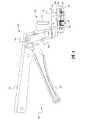
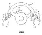
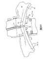
添付図面の特に図1に示したのは、本願開示の教示に従って構成した縫合装置であり、
参照符号20はこの縫合装置の全体を指している。以下に更に詳細に説明するように、こ
の縫合装置は外科手術における切開創の閉鎖処置に用いるのに有用なものであり、その閉
鎖処置を迅速に行えるばかりでなく、その閉鎖処置の際に創縁の位置揃えを高精度で達成
することができ、更には、瘢痕を微細なものとすることができる。ただし当然のことなが
ら、この縫合装置20は、事故などの外傷による裂創の閉鎖処置に用いるのにも有用なも
のである。図1〜図9に示した第1の実施の形態に係る縫合装置20は、互いに縫い合わ
せようとする2つの皮膚部分の下方に定位して、それら皮膚部分の真皮層に縫合糸を引き
込んで装着するように構成されている。また、後に説明する実施の形態は、皮膚の外表面
から表皮層に対して適用するように構成された縫合装置、それに、腹腔鏡下手術に用いる
のに適した縫合装置である。尚、本明細書に開示する数々の実施の形態は皮膚の縫合に用
いる縫合装置であるが、容易に理解されるように、本願開示は皮膚以外の組織に対しても
同様に適用することができる。1 of the accompanying drawings, and in particular, a suturing device constructed in accordance with the teachings of the present disclosure,
図1に示したように縫合装置20はグリップ22を備えており、このグリップ22はハ
ンドル24とトリガ26とで構成されていることに留意されたい。外科医がトリガ26を
握り込んでハンドル24に近付く方向へ揺動させると、作動端30の内部構成部材が駆動
機構28により駆動され、それによって患者の皮膚の真皮層(図1には示されていないが
、後に説明する別の図に示されている)の中に縫合糸32が装着される。It should be noted that the
図2〜図7は、作動端30を更に詳細に示した図である。それらの図から明らかなよう
に、作動端30は第1円弧形針34と第2円弧形針36とを備えており、それら円弧形針
34、36は、それらに共通する回転軸心37を中心として回転し、これについては後に
更に詳細に説明する。作動端30の構成部材の運動は、トリガ26を握り込んでハンドル
24に近付く方向へ揺動させることによって開始される。その操作によって、レバーアー
ム39が枢軸40を中心として揺動し、ラック41を後方へ移動させる。それによってピ
ニオン42が回転し、このピニオン42は駆動軸43に取付けられており、プレート44
に回転可能に支持されている。図から明らかなように、駆動軸43の一端に第1ベベルギ
ヤ45が取付けられており、この第1ベベルギヤ45は、この第1ベベルギヤ45に対し
て直角を成すように配設された第2ベベルギヤ46及び第3ベベルギヤ47と噛合してい
る。第2ベベルギヤ46及び第3ベベルギヤ47が回転することによって、第1円弧形針
34及び第2円弧形針36が回転し、この回転伝達は、2つのベベルギヤ46、47と2
つの円弧形針34、36との間に配設された同軸型の2本の駆動軸48、49によってな
される。図から明らかなように、一方の駆動軸48は中空軸であって、その中に他方の駆
動軸49が嵌挿されており、これによって各々が個別に回転可能とされている。尚、以上
に説明した機構の他にも、様々な機械式及び電気式の伝達機構やギヤ機構を利用すること
ができ、モータを用いた駆動機構なども利用でき、そのような機構を利用したものも本願
開示の範囲に含まれる。2 to 7 are views showing the operating
Is rotatably supported. As is apparent from the figure, a
This is achieved by two
引き続き図4〜図7を参照して、第1円弧形針34及び第2円弧形針36の回転運動の
特性について説明する。皮膚への縫合糸32の装着を行う前の初期状態、即ち休止状態に
あるときには、第1円弧形針34及び第2円弧形針36は作動端30の中に引っ込められ
ている。トリガ26を握り込んでハンドル24に近付く方向へ揺動させると、第1円弧形
針34及び第2円弧形針36が回転する。その際の第1円弧形針34及び第2円弧形針3
6の回転角度は、例えば約180°〜270°であり、ただし正確な回転角度は使用する
定着片(即ち縫合糸32)に応じて異なったものとなる。第1円弧形針34と第2円弧形
針36とは、駆動されて回転することにより、夫々第1皮膚部分と第2皮膚部分とを刺し
貫くようにしてある。また、後に更に詳細に説明するように、第1円弧形針34と第2円
弧形針36とがそのように回転運動することによって、縫合糸32の両端が、夫々第1皮
膚部分と第2皮膚部分との中に引き込まれる。The characteristics of the rotational motion of the first arc-shaped
The rotation angle of 6 is, for example, about 180 ° to 270 °, but the exact rotation angle differs depending on the fixing piece (that is, the suture 32) used. The first arc-shaped
更に図4〜図7を参照して、駆動機構28について詳述する。それらの図から明らかな
ように、作動端30は、互いに縫い合わせようとする第1皮膚部分と第2皮膚部分とのう
ちの、第1皮膚部分を受け入れる第1案内チャネル部50と、第2皮膚部分を受け入れる
第2案内チャネル部52とを備えている。作動端30は更に、それら第1案内チャネル部
50と第2案内チャネル部とを隔てる区画板54を備えている。以上に説明した構成によ
れば、2つの円弧形針34、36が、互いに対向する回転方向に、しかも案内チャネル部
50、52及び区画板54に対して相対的に回転すると共に、互いに縫い合わせようとす
る部分が互いに押付けられる。更にこれによって、皮膚部分間の垂直アライメント及び水
平アライメントが達成され、それら2つの皮膚部分が互いに密接して接合される。Further, the
以下に縫合方法について詳細に説明するが、その前に先ず図8を参照して、縫合糸32
の構成について説明する。ここに示したように、1つの実施の形態に係る縫合糸32は、
第1端58と第2端60とを有する1本のフィラメント56を含み得る。第1端58と第
2端60の各々に1つずつ針ガイド62を備えてもよく、それら針ガイド62は、第1円
弧形針34と第2円弧形針36の夫々に縫合糸32を容易に着脱できるようにするもので
ある。各々の針ガイド62は、例えば、第1円弧形針34及び第2円弧形針36の各々の
尖端66が余裕を持ってその中に進入できる大きさの環状開口部64としてもよい。また
、縫合糸32は、図5〜図8に示したように、1本ずつ個別にカートリッジ68の中に収
容したものとするのもよい。更に、縫合糸32を、カートリッジ68から簡単に取外せる
状態でカートリッジ68に保持するために、縫合糸32とカートリッジ枠部71とを破断
容易な接続部70を介して接続しておき、円弧形針34、36の尖端66がこの接続部7
0を押し破り或いは引き千切ることによって、この接続部70を破断させるようにしてお
くのもよい。また、代替構成例として、縫合糸32をカートリッジ68から簡単に取外せ
る状態でカートリッジ68に保持する手段として、案内チャネル部、溝部、凹部、開口部
などで縫合糸32を保持するようにしてもよい。The suturing method will be described in detail below. Before that, referring first to FIG.
The configuration of will be described. As shown here, the
A
The connecting
更に、カートリッジ枠体71に多数の鋸歯状部75を形成するのもよく、これは、押え
部材などを使用せずとも皮膚を保持できるようにするためのものである。カートリッジ枠
体71は更に、鋸歯状部75を支持するための側方傾斜梁部81を備えたものとするのも
よい。そうした場合には、第1皮膚部分及び第2皮膚部分(不図示)が、側方傾斜梁部8
1と、案内チャネル部50、52と、区画板54との間に保持されて、上述した「外翻」
が形成され、それによって皮膚閉鎖部が非常に効果的に形成されるため、瘢痕も微細なも
のとなる。更に、カートリッジ68は丸ごと交換可能な構成として、例えば縫合処置を実
行する際に新たなカートリッジ68を作動端30に装填するようにするのもよい。或いは
別法として、カートリッジ68は縫合装置20の中に常時装着しておく構成として、縫合
処置を実行する際に交換用の縫合糸32のセットをその中に挿入するようにするのもよい
。In addition, a large number of
1, the
Is formed so that the skin closure is formed very effectively, so that the scar is also fine. Furthermore, the
図9A〜図9Bに示したように、縫合装置20の円弧形針34、36はそれらの先端部
72に夫々に凹部74を形成してもよく、それら凹部74は、カートリッジ68に収容さ
れている縫合糸32に係合して、カートリッジ68から縫合糸32を容易に引き出せるよ
うにするものである。より詳しくは、逆方向運針方式を採用し、針ガイド62を皮膚の中
へ引き込むようにする場合には、円弧形針34、36の凹部74の形状を、針先方向へ行
くに従って陥凹して行く形状にしておく。これにより、例えば縫合装置20のトリガを解
放することで、円弧形針34、36を皮膚から抜脱する方向に回転させたときに、それら
円弧形針34、36の夫々の凹部74が、夫々の針ガイド62に係合するようになる。一
方、順方向運針方式を採用し、針ガイド62を皮膚の中へ押し込むようにする場合には、
円弧形針34、36の凹部74の形状を、針元方向へ行くに従って陥凹して行く形状にし
ておく。これにより、例えば縫合装置20のトリガを握り込むことで、円弧形針34、3
6を皮膚に穿刺して挿入する方向に回転させたときに、それら円弧形針34、36の夫々
の凹部74が夫々の針ガイド62に係合するようになる。尚、図9A〜図9Bの実施の形
態では、円弧形針34、36の内周縁に凹部74が形成されているが、それらに改変を加
えて、円弧形針34、36の外周縁に凹部74を形成した実施の形態とすることも可能で
ある。9A to 9B, the
The shape of the
When the 6 is rotated in the direction of puncturing and inserting the skin, the respective
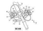
縫合糸32を皮膚に装着するプロセスを実行している間、縫合糸32と円弧形針34、
36との係合を確実に維持できるようにするためには、図10A〜図10Iに示したよう
なスライダプレート73などを備えるとよい。スライダプレート73は、針ガイド62を
対応する円弧形針34、36の回転経路上に一時的に保持するものである。更に、図10
A〜図10Iに示した逆方向運針方式に対応したスライダプレート73は、縫合装置20
のトリガが握り込まれたときに円弧形針34、36が対応する針ガイド62の開口部に進
入できるようにすると共に、縫合装置20のトリガが解放されたときに、針ガイド62が
対応する円弧形針34、36の凹部74に捕捉されて係合するようにし、更に、その係合
状態を、縫合糸32が皮膚に装着されるまでの間、維持できるようにするものである。図
10A〜図10Bに示したように、スライダプレート73は、カートリッジ68の中に摺
動可能に配設されるようにしてもよく、また、スライダプレート73の形状は、縫合糸3
2の針ガイド62がこのスライダプレート73に嵌合できる形状としてもよい。また、図
10Cに示したように、スライダプレート73は、縫合糸32の針ガイド62が嵌合して
係合する一群の溝部77を備えてもよい。図10A〜図10Iに示した実施の形態は、環
形状の針ガイド62に対応するためのスライダプレート73であり、針ガイドの形状がこ
れと異なるものである場合には、スライダプレート73の形状をその針ガイドの形状に適
合するようなものとすればよいことを理解されたい。While performing the process of attaching the
In order to reliably maintain the engagement with the
The
Allows the
The two needle guides 62 may have a shape that can be fitted to the
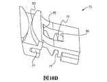
更に、スライダプレート73は、カートリッジ68に対して相対的に摺動可能にしても
よく、円弧形針34、36の回転に応動して移動することができる。また、図10Dに更
に示したように、スライダプレート73には、そのカートリッジ68と摺接する部分に、
付勢機構を収容するための凹部83が形成されている。更に、その付勢機構は、スプリン
グなどを用いた機構であって、スライダプレート73を、カートリッジ68に対する所定
の相対位置へ付勢するものとしてよい。この所定の相対位置は、実質的に中立の位置とす
る場合もあれば、側方位置とする場合もあり、それらを適宜組合せた位置とすることもあ
る。スライダプレート73は更に、複数の当接面を有するカムスロット85を備えてもよ
い。それら当接面は、円弧形針34、36の内周縁及び/または外周縁と当接し、また特
に、円弧形針34、36の先端部72の内周縁及び/または外周縁と当接するものである
。更に詳しく説明すると、カムスロット85のそれら当接面は、それら当接面がカムスロ
ット85の中へ進入してきた円弧形針34、36の先端部72の外周縁ないし内周縁と当
接することによって、その円弧形針34、36の凹部74とそれに対応する針ガイド62
とを確実に係合させることができるように、その寸法、角度、及び全体形状を定めてよい
。Further, the
A
The size, angle, and overall shape may be determined so that the two can be reliably engaged.
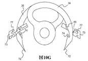
図10E〜図10Fに示したのは、逆方向運針型の構成であるが、この構成において、
例えば縫合装置20のトリガが操作されて円弧形針34、36が穿刺方向へ回転すると、
円弧形針34、36の先端部72の外周縁がカムスロット85の内向き当接面に当接して
この当接面を押圧し得るため、スライダプレート73は円弧形針34、36及びカートリ
ッジ68に対して相対的に外方へ摺動して移動する。このスライダプレート73の外方へ
の移動は、カムスロット85の外向き当接面と円弧形針34、36の内周縁とが当接する
ことにより規制され得、その状態を示したのが図10G〜図10Hである。スライダプレ
ート73とカートリッジ68との間に配設されている付勢機構も、円弧形針がカムスロッ
トの中を穿刺方向へ移動する際のスライダプレート73の外方への移動を規制するように
機能し得る。また、縫合装置20のトリガが解放されて、円弧形針34、36が抜脱方向
へ回転すると、図10Iに更に示したように、カムスロット85の当接面が円弧形針34
、36の内周縁及び/または外周縁と当接し得、それによって針ガイド62が円弧形針3
4、36の凹部74の中に捕捉される。以上から明らかなように、円弧形針34、36は
スライダプレート73のカムスロット85に対して進入及び退去が実質的に自由にでき、
そして、円弧形針34、36の形状及び移動に従って、2つの針ガイド62が夫々円弧形
針34、36に確実に捕捉される。この針ガイド62の捕捉は、縫合糸を皮膚に装着する
プロセスの開始に先立って行われ、その装着のプロセスが完了するまで捕捉された状態が
維持される。尚、順方向運針型の構成とした場合、即ち、凹部74の形状を、円弧形針3
4、36が抜脱方向ではなく穿刺方向へ回転しているときに、この凹部74が針ガイド6
2を捕捉する形状とした円弧形針34、36を使用している場合にも、スライダプレート
73は同様に機能し得ることを理解されたい。FIGS. 10E to 10F show the configuration of the reverse direction hand movement type. In this configuration,
For example, when the trigger of the
Since the outer peripheral edge of the
, 36 can be brought into contact with the inner and / or outer peripheral edge, whereby the
4 and 36 are captured in the
Then, according to the shape and movement of the arc-shaped
4 and 36 are rotated in the puncture direction instead of the removal direction, the
It should be understood that the
次に図11A〜図11Jについて説明すると、それらの図は、本願開示の教示に関連し
て使用することのできる様々な実施の形態に係る縫合糸32を開示したものである。例え
ば図1〜図9に示した縫合糸32は、そのフィラメント56の表面が滑らかであったが、
図11A〜図11Fに示した縫合糸32は、円筒面を成すそのフィラメント56の表面か
ら径方向外方へ突出した幾つもの突出片76などの付加片を備えている。図から明らかな
ように、様々な実施の形態のうちには、全ての付加片76が同一方向へ突出しているもの
もあれば、互いに逆方向へ突出した付加片76を備えているものもある。また、傾斜部を
画成している付加片76を備える場合には、全ての付加片76の傾斜部の方向を一方向に
することによって、その方向への縫合糸32の挿入を容易にする一方で、それとは逆方向
への抜脱を阻止することができる。かかる突出片などの付加片76は、例えば図11A〜
図11Fに示したように、その概略形状を、球形状、円錐形状、角錐形状、板形状、等々
とした、二次元又は三次元構造のものとすることができ、また、その側面ないし側縁78
に傾斜部を有するものとすることで、皮膚の組織への縫合糸32の挿入を容易にする一方
で、それとは逆方向への縫合糸32の移動に対しては皮膚の組織が引っ掛かるようにする
ことができる。更に、突出片などの付加片76の形状は、複数の形状を組合せた複合形状
としてもよく、例えば図11Eに示したように、円錐形状部に板形状部を付加して構成し
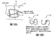
た係止片76とするのもよい。突出片76は、縫合糸32の皮膚への装着後に、第1皮膚
部分及び第2皮膚部分を良好に把握保持する摩擦干渉手段として機能するばかりでなく、
装着された縫合糸32が最終的な形状を呈した状態で、突出片76が皮膚の組織に噛合す
ることにより、閉鎖部位をより密接させて接合することができ、更には、以下に説明する
ように戻り移動と中寄り移動との両方を防止することもできる。即ち、そのような突出片
76によって、図12A〜図12Bに示したように、中寄り移動と戻り移動との両方が防
止される。ここで戻り移動というのは、縫合糸が皮膚に装着された後に、その縫合糸の交
点において、縫合糸の装着時の移動方向とは逆方向に縫合糸が移動して皮膚から抜脱して
しまうことをいい、また、中寄り移動とは、図12Aに示したように、閉螺旋状縫合によ
って皮膚に装着された縫合糸が、その中央部分を超えて横方向内方へずれてしまうことを
いう。Referring now to FIGS. 11A-11J, the figures disclose
The
As shown in FIG. 11F, the schematic shape may be a two-dimensional or three-dimensional structure such as a spherical shape, a conical shape, a pyramid shape, a plate shape, etc., and its side surface or side edge. 78
By having the inclined portion on the side, the insertion of the
In a state where the attached
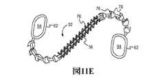
特に図11G〜図11Jに示したように、本願開示の教示に従って構成する縫合糸32
は、更に別の様々な実施の形態として構成することが可能である。図11A〜図11Fに
示した様々な縫合糸32では、そのフィラメント56に突出片76及び/または傾斜部画
成部材78が設けられていたのに対して、図11G〜図11Jに示した縫合糸32では、
そのフィラメント56の表面は実質的に滑らかなままであり、突出片76及び/または傾
斜部画成部材32は針ガイド62の方に設けられている。先に示した実施の形態と同様に
、これら図11G〜図11Jの縫合糸32も、それら縫合糸32の端部を対応する方向へ
挿入することは容易で、逆方向への抜脱は阻止されるように構成されている。より詳しく
は、針ガイド62は、皮膚への挿入時には少なくとも部分的に潰れて細くなることによっ
て、皮膚からの物理的な抵抗力が小さくなり、一方、逆方向に引っ張られたときには拡が
ることでその抵抗力が大きくなり、もって抜脱を阻止するように構成されている。これに
加えて、または任意に、図11Gに想像線で示したように、縫合糸32の各々の端部に、
2つ以上の針ガイド62を設けるようにしてもよく、こうすることによって、挿入後の皮
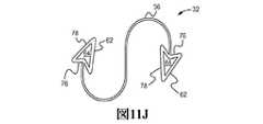
膚からの抜脱に対して更に大きな抵抗力を発揮することができる。図11Gに示した針ガ
イド62は先端部が丸みを帯びた形状とされているが、これと異なる実施の形態として、
針ガイド62の先端部に傾斜を設けて先端部を尖った形状とするのもよく、それによって
挿入を更に容易にすることができ、そのようにした実施の形態を示したのが、図11H〜
図11Jである。更に、針ガイド62は、その全体形状を、環形状、円形状、楕円形状、
長円形状、四角形状、三角形状、多角形状、またはその他の適当な形状とし、そして少な
くともその外縁形状が、皮膚への挿入を容易にして抜脱を阻止するような形状であるよう
にするとよい。更に、針ガイド62は、その形状を、開口部を持たない単なる膨出部形状
とし、ただしその寸法及び構成を、皮膚への挿入に際して第1円弧形針34及び第2円弧
形針36の凹部74がその針ガイドに係合することができ、また、皮膚の組織に装着され
たならば戻り移動を阻止することができる寸法及び構成としたものとするのもよい。更に
、以上のいずれの形態の縫合糸に関しても、複数の縫合糸を収容するマガジン(不図示)
を縫合装置20に備えて、1つの縫合糸を皮膚に装着したならば、後続の縫合糸が自動的
にその収容位置をひとつずつ前に進めるようにするのもよい。In particular, as shown in FIGS. 11G-11J, a
Can be configured as various other embodiments. In
The surface of the
Two or more needle guides 62 may be provided, and by doing so, it is possible to exert even greater resistance to withdrawal from the skin after insertion. The
The tip of the
FIG. 11J. Furthermore, the
An oval shape, a quadrangular shape, a triangular shape, a polygonal shape, or other suitable shape may be used, and at least the outer edge shape may be a shape that facilitates insertion into the skin and prevents withdrawal. . Furthermore, the shape of the
If the
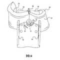
動作について説明すると、縫合装置20を用いて例えばヒトの皮膚の切開創の閉鎖処置
を実行することによって、その閉鎖処置を迅速かつ効果的に行うことができ、また、閉鎖
部位の両側の2つの皮膚部分の間のアライメントを高精度で達成することができ、閉鎖部
位の創縁どうしを密接させることができ、更には、縫合痕を微細なものとすることができ
る。図13〜図14は、本願開示の教示に従ってテストフィクスチャとして構成した縫合
装置86の第1案内チャネル部82と第2案内チャネル部84とに、夫々第1皮膚部分7
9と第2皮膚部分80とが挿入されているところを示した図である。本願開示を完全なも
のとするために付言しておくと、図13〜図14は単に、縫合装置20のテストフィクス
チャとして構成した縫合装置によって、ある皮膚のサンプルに対する閉鎖処置が行われて
いるところを示しているに過ぎない。実際の切開創の閉鎖処置においては、例えばその切
開創はヒトの身体のどこかの部位に存在するものであり、作動端30をその切開創より下
方の皮下に定位して、2つの皮膚部分79、80を案内チャネル部50、52の中に挿入
し、それら皮膚部分79、80の皮下側をカートリッジの枠部71の鋸歯状部75の上に
載置するなどの手順が取られてもよい。縫合装置20を使用する可能な方法のうちの1つ
は、縫合装置20を用いて切開創89の一端から縫合糸32の装着を開始し、そして、切
開創に沿って縫合装置を手前に移動させては次の縫合糸を装着することができる。この手
順を反復して実行することによって切開創を最後まで閉鎖すればよく、その経過を示した
のが図15A〜図15Eである。更に、第1皮膚押え部材90及び第2皮膚押え部材92
を備えてもよく、これらの部材は、上方へ揺動することによって皮膚部分79、80の夫
々の皮下層94に係合するように構成されている。かかる皮膚押え部材90、92は、実
施の形態によっては不要なこともあり、また任意に備えるようにしてもよい実施の形態も
ある。例えば図1〜図9に示した実施の形態は、それら皮膚押え部材と実質的に同一の機
能を果たすように構成された鋸歯状部75を備えているため、かかる皮膚押え部材は不要
である。In operation, the closure procedure can be performed quickly and effectively, for example by performing a closure procedure on a human skin incision with the
It is the figure which showed the place where 9 and the
These members are configured to engage the respective
また別の使用法として、例えば次のような方法があり、その方法では、縫合装置20を
用いて最初に切開創89の略々中点の位置に縫合糸32を装着し、それによってその切開
創89を2つの部分に分ける。続いて、そのようにして分けた切開創89の2つの部分の
各々を、次の縫合糸32を同様に装着することによって、更に小さな2つずつの部分に分
け、以下、この手順を反復して実行することによってその切開創89の全体を閉鎖する。
更に別の使用法として、縫合装置20を用いて切開創89の両端の各々から縫合糸32を
装着して行き、夫々に切開創89の中点まで縫合糸32を装着することによって、切開創
89の全体を閉鎖するという方法もある。縫合装置20の使用法としてはその他にも様々
なものがあり、それらは当業者には容易に想到し得るものである。As another method of use, for example, the following method is used. In this method, the
As yet another usage, the
引き続き図13及び図14について説明すると、縫合装置20のトリガ26を握り込ん
でハンドル24に近付く方向へ揺動させると、第1円弧形針34及び第2円弧形針36が
回転して、第1円弧形針34は第1皮膚部分79の真皮層94を刺し貫き、第2円弧形針
36は第2皮膚部分80の真皮層94を刺し貫く。使用している一対の円弧形針34、3
6が図9Aに示した形状のものである場合には、皮膚への縫合糸32の装着は逆方向運針
方式で行うことができる。その場合、第1円弧形針34及び第2円弧形針36を回転限度
一杯まで回転させればよく、それによって、縫合糸32の両端の2つの針ガイド62を捕
捉することができ、それに続いて、握り込んでいた縫合装置20のトリガ26を解放すれ
ば、円弧形針34、36が抜脱方向に回転するため、2つの針ガイド62が互いに逆方向
に引っ張られ、それら2つの針ガイド62が、夫々第1皮膚部分79と第2皮膚部分80
との中に引き込まれる。一方、使用している一対の円弧形針34、36が、図9Bに示し
た形状のものである場合には、皮膚への縫合糸32の装着は順方向運針方式で行うことが
できる。その場合、縫合糸32は、針ガイド62によって、各々の円弧形針が最初に刺し
貫く皮膚部分へ押し込まれ、第1皮膚部分79と第2皮膚部分80との間の接合面96を
横切り、更に他方の皮膚部分へ押し込まれる。順方向運針方式と逆方向運針方式とのいず
れを採用している場合でも、2つの円弧形針34、36は同時に略々同じ距離だけ回転移
動し、2つの針ガイド62は互いに反対方向へ略々同じ長さだけ押し込まれ或いは引き込
まれる。これとは別の実施の形態として、2つの円弧形針34、36が略々同じ距離だけ
回転移動するが、その角速度が互いに異なるような実施の形態とすることもできる。13 and 14, when the
When 6 has the shape shown in FIG. 9A, the
And is drawn into. On the other hand, when the pair of
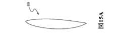
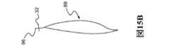
順方向運針方式と逆方向運針方式とのいずれを採用している場合でも、縫合糸32の皮
膚への装着が完了するまでに、2つの円弧形針34、36はいずれも、第1皮膚部分79
と第2皮膚部分80との両方を刺し貫いている。また、皮膚への装着前に、平面状、二平
面状、多平面状、等々の非螺旋状であった縫合糸32の形状は、皮膚への装着後には、実
質的に螺旋状に変化している。更に、順方向運針方式と逆方向運針方式とのいずれを採用
している場合でも、縫合装置20を用いて形成する創閉鎖部は、閉螺旋状縫合によるもの
とすることも、また開螺旋状縫合によるものとすることもでき、縫合糸32を装填する初
期位置を、円弧形針34、36に対するいかなる相対位置とするかによって、どちらでも
選択することができる。例えば図16A〜図16Nに示したように、逆方向運針型の1台
の縫合装置20を使用して、また、同じ縫合糸32を使用して、単に、その縫合装置20
の使用に先立って縫合装置20に装填する縫合糸32の初期位置を適宜設定するだけで、
閉螺旋状縫合と開螺旋状縫合とのいずれによる創閉鎖部でも形成することができる。尚、
図面には示さないが、順方向運針型の縫合装置についても、1台の縫合装置20を同様に
使用して、また、同じ縫合糸32を使用して、単に、その縫合装置20の使用に先立って
縫合装置20に装填する縫合糸32の初期位置を適宜設定するだけで、閉螺旋状縫合と開
螺旋状縫合とのいずれによる創閉鎖部でも形成することができる。Regardless of which of the forward-direction and reverse-direction movement methods is adopted, the two arc-shaped
And the
By simply setting the initial position of the
The wound closure part can be formed by either a closed spiral suture or an open spiral suture. still,
Although not shown in the drawings, for a forward-handed suture device, a
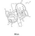
特に図16A〜図16Gについて説明すると、それらの図に示したように、逆方向運針
型の縫合装置20を用いて、閉螺旋状縫合による創閉鎖部を形成することができ、その場
合には、縫合糸32を装填する初期位置を図16Aに示した位置にする。縫合糸32がこ
の図に示した初期位置に装填されているときには、その縫合糸32の両端の2つの針ガイ
ド62の開口部に夫々円弧形針34、36が進入可能な位置関係にあり、この状態で縫合
装置20のトリガを握り込めば、円弧形針34、36がそれら針ガイド62の夫々の開口
部に進入し、それら円弧形針34、36の夫々の凹部74によって夫々の針ガイド62が
捕捉される。閉螺旋状縫合による創閉鎖部を形成するためには、更に、図16Aに示した
ように、縫合糸32のフィラメント56を、一方の円弧形針34の先端部72の外側を通
り、2つの円弧形針34、36の先端部72の間を通り、他方の円弧形針36の先端部7
2の外側を通るように取回しておく。この状態で縫合装置20のトリガを操作して円弧形
針34、36を回転させると、図16B〜図16Cに示したように、それら円弧形針の先
端部72が夫々、対応する針ガイド62に近付く方向に移動し、ついには図16D〜図1
6Fに示したように、夫々の凹部74が夫々の針ガイド62に係合する。こうして凹部7
4が針ガイド62に係合した後に、握り込んでいた縫合装置20のトリガを解放すれば、
針ガイド62が逆方向運針方式で皮膚の組織の中へ引き込まれ、それによって、図16G
に示したように、閉螺旋状縫合による創閉塞部が形成され、即ち、縫合糸を閉螺旋状に結
んだような形状の創閉鎖部が形成される。In particular, FIGS. 16A to 16G will be described. As shown in these drawings, a wound closure portion by closed spiral stitching can be formed using the reverse direction needle-operated
Route around the outside of 2. When the
As shown in FIG. 6F, each
If the trigger of the
The
As shown in FIG. 4, a wound closure part is formed by closed spiral stitching, that is, a wound closure part shaped like a suture tied in a closed spiral form.
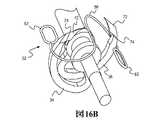
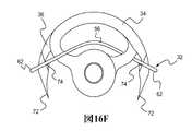
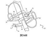
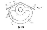
次に図16H〜図16Nについて説明すると、それらの図に示したように、逆方向運針
型の縫合装置20を用いて、開螺旋状縫合による創閉鎖部を形成することもでき、その場
合には、縫合糸32を装填する初期位置を図16Hに示した位置にする。縫合糸32がこ
の図に示した初期位置に装填されているときには、図16Aに示した閉螺旋状縫合に関す
る初期位置の場合と同様に、その縫合糸32の両端の2つの針ガイド62の開口部に夫々
円弧形針34、36が進入可能な位置関係にあり、この状態で縫合装置20のトリガを握
り込めば、円弧形針34、36が対応する針ガイド62の夫々の開口部に進入し、それら
円弧形針34、36の夫々の凹部74によって夫々の針ガイド62が捕捉される。開螺旋
状縫合による創閉鎖を形成するためには、更に、縫合糸32のフィラメント56を、図1
6Hに示したように、円弧形針34、36の夫々の先端部72から離れる方向へ延出して
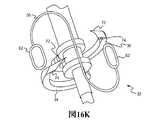
その中央部が2本の円弧形針34、36の先端部72の間を通るように取回しておく。こ
の状態で縫合装置20のトリガを操作して円弧形針34、36を回転させると、図16I
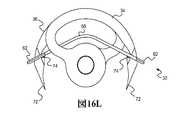
〜図16Kに示したように、それら円弧形針の先端部72が対応する針ガイド62に近付
く方向に移動することができ、ついには図16L〜図16Mに示したように、夫々の凹部
74が夫々の針ガイド62に係合する。こうして凹部74が針ガイド62に係合した後に
、握り込んでいた縫合装置20のトリガを解放すれば、針ガイド62が逆方向運針方式で
皮膚の組織の中へ引き込まれ、それによって、図16Nに示したように、開螺旋状縫合に
よる創閉鎖部が形成され得る。Next, FIGS. 16H to 16N will be described. As shown in these drawings, the wound closure part by the open spiral suture can be formed by using the reverse-direction-hand-operated
As shown in FIG. 6H, the arc-shaped
As shown in FIG. 16K, the
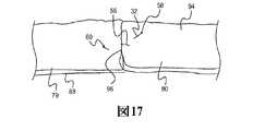
図17〜図18に示した実施の形態は、具体例の創部に挿入された縫合糸により形成さ
れた同様の開螺旋状縫合による創閉鎖部を例示したものである。例えば図17には、縫合
糸が挿入された第1皮膚部分79及び第2皮膚部分80の真皮層94が示されており、縫
合糸のフィラメント56は、第1皮膚部分79及び第2皮膚部分80の中を延在すると共
に、それら皮膚部分の接合面96を横切って延在しており、このフィラメント56の第1
端58及び第2端60は真皮層94の外へ延出している。図18の創閉鎖部も、図17の
創閉鎖部とほぼ同じものであり、ただし、縫合糸によってそのような創閉鎖部を幾つも並
べて形成したところを単に示したものである。おそらく最も重要なことは、縫合糸を挿入
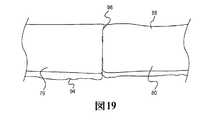
して創閉鎖部を形成する処置が完了したならば、第1皮膚部分79及び第2皮膚部分80
の表皮層88が、図19に示したような外観を呈することである。同図から明らかなよう
に、第1皮膚部分79と第2皮膚部分80との間の水平アライメントが達成されており、
そのため、接合面96は直線状であり密接に接合されている。更に、第1皮膚部分79と
第2皮膚部分80との間の垂直アライメントも達成されており、そのため両者は同一面上
に位置している。この点を分かりやすく示したのが、図20A〜図20Cの比較図である
。The embodiment shown in FIGS. 17 to 18 exemplifies a wound closing portion formed by a similar open spiral suture formed by a suture thread inserted into a wound portion of a specific example. For example, FIG. 17 shows a
The
The
Therefore, the joining
先ず、図20Aに示したのは、マニュアル縫合により形成される創閉鎖部である。図か
ら明らかなように、第1皮膚部分79と第2皮膚部分80との間の垂直アライメントと水
平アライメントとの両方が達成されており、この場合、縫合痕は微細なものとなる。ただ
し、先に述べたように、マニュアル縫合は時間のかかる退屈な作業である上に、医療従事
者は縫合針を誤って自身に刺すことによる感染の危険性に曝されている。次に、図20C
に示したのは、従来の自動式の皮膚ステープラーを使用して吸収性ステープルを装着する
ことにより形成される創閉鎖部である。図から明らかなように、第1皮膚部分79と第2
皮膚部分80との間の垂直アライメント及び水平アライメントが達成されていないばかり
か、表皮層88から立ち上がった顕著な突条様の部分98が形成されており、これによっ
て患者の皮膚には甚だしい縫合痕が残されることになる。これに対して、本願開示の教示
に従って行われる創閉鎖処置により形成される創閉鎖部を示したのが、図20Bである。
図から明らかなように、接合面96において2つの皮膚部分の間の水平アライメントと垂
直アライメントとの両方が達成されており、接合面96は密接に接合されている。更に、
垂直方向及び水平方向の密接が高精度で達成されているため、縫合痕が微細なものとなり
、従って、図20Cに示した従来の皮膚ステープラーを使用したときのように醜い縫合痕
が残るということがない。更に、本願開示に係る縫合装置20によれば、縫合処置が半自
動的に行われるため、図20Aに示したマニュアル縫合の場合のように時間がかかるとい
うこともない。First, what is shown in FIG. 20A is a wound closure portion formed by manual stitching. As is apparent from the figure, both vertical alignment and horizontal alignment between the
Shown is a wound closure formed by applying absorbent staples using a conventional automatic skin stapler. As is apparent from the figure, the
Not only vertical and horizontal alignment with the
As can be seen, both horizontal and vertical alignment between the two skin portions is achieved at the
Since close contact in the vertical direction and the horizontal direction is achieved with high accuracy, the stitch mark becomes fine, and therefore, an ugly stitch mark remains when the conventional skin stapler shown in FIG. 20C is used. There is no. Furthermore, according to the
従って、逆方向運針型の縫合装置を用いて皮膚に縫合糸32を装着することで創閉鎖処
置を実行する場合に、その装着に先立って縫合糸32を初期位置に装填するときの装填の
仕方によって、閉螺旋状縫合による創閉鎖処置と開螺旋状縫合による創閉鎖処置とのどち
らを実行することも可能となっている。尚、ここでは、逆方向運針型の縫合装置を用いた
場合の閉螺旋状縫合及び開螺旋状縫合による創閉鎖処置についてのみ説明しているが、容
易に理解されるように、順方向運針型の縫合装置を用いて皮膚に縫合糸32を装着する場
合にも、以上と同様に、その装着に先立って縫合糸32を初期位置に装填するときの装填
の仕方によって、閉螺旋状縫合による創閉鎖処置と開螺旋状縫合による創閉鎖処置とのど
ちらを実行することも可能である。Therefore, when the wound closing procedure is performed by attaching the
次に図21〜図27について説明すると、それらの図に開示したのは、皮膚の表皮層に
適用することのできる別の実施の形態に係る縫合装置である。即ち、先に説明した実施の
形態では、縫合装置を創部に挿入して、一対の円弧形針をそれらの先端部を上方へ突き上
げるように回転させて皮膚の皮下層及び真皮層を刺し貫くようにしたものであったが、そ
れに対して、図21〜図27に示したこの別の実施の形態では、縫合装置を皮膚の真皮層
の表面上に定位して、縫合糸を下方へ引き込むことで、皮膚の表皮層及び真皮層の中へ引
き込んで装着するようにしたものである。この別の実施の形態では、縫合装置のその他の
部分の構成は、先に説明した実施の形態のものと同じであるため、同一構成部分について
は説明を省略することとする。尚、図面中では、その構成要素に対して、先に説明した実
施の形態における対応する構成要素の参照番号に「100」を加えた参照番号を付してあ
る。Next, FIGS. 21 to 27 will be described. The suture device according to another embodiment that can be applied to the epidermis layer of the skin is disclosed in these drawings. That is, in the above-described embodiment, the suturing device is inserted into the wound portion, and the pair of arc-shaped needles are rotated so as to push up their distal end portions upward to pierce the subcutaneous layer and the dermis layer of the skin. In contrast, in this alternative embodiment shown in FIGS. 21-27, the suturing device is positioned on the surface of the dermis layer of the skin and the suture is pulled downward. Thus, it is drawn into the epidermis layer and the dermis layer of the skin for wearing. In this other embodiment, the configuration of the other parts of the suturing device is the same as that of the above-described embodiment, and thus the description of the same component will be omitted. It should be noted that in the drawings, a reference number obtained by adding “100” to the reference number of the corresponding component in the above-described embodiment is attached to the component.
次に図28について説明すると、同図に示したのは、別の実施の形態に係る縫合装置の
駆動機構228である。図示した駆動機構228は、例えば図13〜図14に示したテス
トフィクスチャとして構成した縫合装置86などに用い得るものであり、2つの円弧形針
234、236を互いに逆方向に回転させるための、先に説明した駆動機構とはまた別の
構成の駆動機構を提供するものである。より詳しくは、駆動機構228は、同心的に配置
された2本の駆動軸248、249を備えており、それら同心的な駆動軸248、249
の各々は、夫々に対応する円弧形針236、234に連結されている。また、それら同心
的な駆動軸248、249は、夫々に対応するギヤ246、247に連結されており、こ
れによって、ギヤ246、247が回転すれば、夫々に対応する円弧形針236、234
も回転するようにしてある。更に、第1ギヤ246は第1ラック241によって、また第
2ギヤ247は第2ラック242によって、夫々個別に回転させられるようにすることが
できる。尚、第2ラック242は、図を見やすくするために図28には示していないが、
第1ラック241と反対側に、第1ラック241と同様に配設されている。以上の構成に
よれば、第1ラック241及び第2ラック242を下方に押動すると、ギヤ246とギヤ
247とが互いに逆方向に回転する。そして、それらギヤ246、247の回転によって
、同心的な2本の駆動軸248、249が互いに逆方向に回転し、更に、それらに対応す
る2つの円弧形針236、234も互いに逆方向に回転する。これによって、本願開示の
教示に沿った縫合糸32の皮膚への装着が行われる。Next, FIG. 28 will be described. FIG. 28 shows a
Are connected to corresponding
Also designed to rotate. Further, the
Similar to the
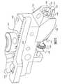
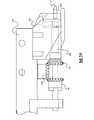
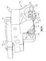
図29〜図31に示したのは、本願開示の更に別の実施の形態である。この実施の形態
は腹腔鏡下手術に用いることのできる縫合装置300である。即ち、この縫合装置300
は、皮膚の真皮層を対象としたものではなく、また表皮層や皮下層を対象としたものでも
なく、体腔深部の部位を縫合することのできる縫合装置である。そのため、この縫合装置
を使用する場合には、皮膚に比較的小さなアクセス用の切開創を形成して、その切開創を
通してこの縫合装置を体内に挿入することにより、内臓や筋組織などの縫合処置を必要と
する様々な組織にアクセスできるものである。そのような使用法を可能にするために、こ
の縫合装置300は細長い駆動軸302を備えたものとされていることに留意されたい。
駆動軸302はハンドル304から延出しており、ハンドル304は操作部材であるトリ
ガ306を備えている。他の実施の形態と同様に、トリガ306を操作すると2つの円弧
形針308、310が回転する。シュラウド312がそれら円弧形針308、310を囲
繞している。この腹腔鏡手術用の縫合装置300は、カメラなどのナビゲーション装置と
共に使用され、そうすることで、円弧形針を体内の縫合を必要とする部位へ正確に到達さ
せることができる。以上から明らかなように、本願開示の教示は、切開創の閉鎖処置とい
う用途に限られず、更に、侵襲を可及的に小さくするための腹腔鏡下手術などの用途にも
適したものである。例えば、以上に開示した固定法は、腹腔鏡下ヘルニア修復術において
人工素材メッシュを固定するという用途にも適用可能である。手術に伴う侵襲をより小さ
くしようとするトレンドが継続している現在、本願開示に係る固定法が適用される機会は
更に増大し続けるであろう。FIG. 29 to FIG. 31 show still another embodiment of the present disclosure. This embodiment is a
Is not intended for the dermis layer of the skin, nor for the epidermis layer or the subcutaneous layer, and is a suturing device capable of suturing a deep part of a body cavity. Therefore, when using this suturing device, a relatively small incision for access is formed in the skin, and the suturing device is inserted into the body through the incision so that a suturing treatment for internal organs or muscle tissue is performed. It is accessible to various organizations that need it. It should be noted that the
The
以上から明らかなように、本願開示として以上に記載した医用装置によれば、縫合糸を
装着することによってヒトの皮膚の開口部を閉鎖する閉鎖処置を、迅速に且つ高い信頼性
をもって行うことができる。この医用装置は、縫合糸で縫い合わせることに要する時間を
マニュアル縫合の場合と比べて大幅に短縮できるのみならず、第1皮膚部分と第2皮膚部
分との位置揃えを水平方向と垂直方向との両方に関して高精度で達成することができ、そ
のため、創部の完治後に大きな瘢痕が残ることがない。更に、以上に説明したように構成
要素を組合せて構成した縫合装置によれば、第1皮膚部分と第2皮膚部分とは、創部が完
治するまで互いに密接した状態に保持され、それによって、治癒が早まると共に完治後の
瘢痕も微細なものとなる。As is apparent from the above, according to the medical device described above as the disclosure of the present application, the closing treatment for closing the opening of the human skin by attaching the suture can be performed quickly and with high reliability. it can. This medical device not only can significantly reduce the time required for sewing with a suture compared with the case of manual stitching, but also aligns the first skin portion and the second skin portion between the horizontal direction and the vertical direction. It can be achieved with high accuracy for both, so that no large scars remain after the wound is completely cured. Furthermore, according to the suturing device configured by combining the components as described above, the first skin portion and the second skin portion are held in close contact with each other until the wound is completely cured, thereby healing. As soon as it gets faster, the scar after the cure becomes finer.
Claims (14)
Translated fromJapanese第1回転方向に回転することで、縫合しようとする第1皮膚部分の真皮層を刺し貫き、
更に、縫合しようとする第2皮膚部分の真皮層を刺し貫くようにした、第1円弧形針と、
前記第1回転方向とは逆方向の第2回転方向に回転することで、縫合しようとする前記
第2皮膚部分の真皮層を刺し貫き、更に、縫合しようとする前記第1皮膚部分の真皮層を
刺し貫くようにした、第2円弧形針と、
装着前の前記第1円弧形針及び第2円弧形針の近傍に縫合糸を一時的に保持するように
構成されたカートリッジと、
装着時に前記縫合糸に係合し、且つ、前記カートリッジから該縫合糸を引き出すように
構成された、前記第1円弧形針及び第2円弧形針の夫々に形成された凹部と、
複数の鋸歯状部を備える第1側方傾斜梁部及び第2側方傾斜梁部を有し、該第1及び第
2側方傾斜梁部、並びに該複数の鋸歯状部が、縫合しようとする前記第1及び第2皮膚部
分を保持するように構成されている、カートリッジ枠体と、
ユーザに操作されることで、前記第1円弧形針及び前記第2円弧形針を回転させ、もっ
て、前記第1円弧形針及び前記第2円弧形針に取外し可能に取付けられた縫合糸の挿入を
行うようにした、駆動機構と、
を備えたことを特徴とする縫合装置。In the suturing device,
By rotating in the first rotation direction, the dermis layer of the first skin part to be sutured is pierced,
A first arc-shaped needle adapted to pierce the dermis layer of the second skin portion to be sutured;
By rotating in a second rotation direction opposite to the first rotation direction, the dermis layer of the second skin portion to be sutured is pierced and further, the dermis layer of the first skin portion to be sutured A second arc-shaped needle that pierces the needle,
A cartridge configured to temporarily hold a suture in the vicinity of the first arc-shaped needle and the second arc-shaped needle before mounting;
A recess formed in each of the first arcuate needle and the second arcuate needle configured to engage the suture when mounted and to pull the suture out of the cartridge;
A first side inclined beam portion and a second side inclined beam portion each having a plurality of serrated portions, and the first and second side inclined beam portions and the plurality of serrated portions are to be sewn. A cartridge frame configured to hold the first and second skin portions;
By being operated by the user, the first arc-shaped needle and the second arc-shaped needle are rotated, and are detachably attached to the first arc-shaped needle and the second arc-shaped needle. A drive mechanism for inserting a suture,
A suturing device comprising:
たことを特徴とする請求項1記載の縫合装置。2. The suturing apparatus according to claim 1, wherein the cartridge includes a plurality of sutures accommodated in the cartridge before being mounted.
とも1つの平面内に存在する平面内形状であり、該第2形状は開螺旋形状と閉螺旋形状と
のうちの1つの形状であることを特徴とする請求項1記載の縫合装置。The shape of the suture is deformable from a first shape to a second shape, and the first shape is an in-plane shape existing in at least one plane, and the second shape is an open spiral shape and a closed spiral shape. The suturing device according to claim 1, wherein the suturing device has one shape.
ャネル部との間に配設された区画板とを更に備えたことを特徴とする請求項1記載の縫合
装置。2. The apparatus according to claim 1, further comprising a first guide channel portion, a second guide channel portion, and a partition plate disposed between the first guide channel portion and the second guide channel portion. The suturing device as described.
刺方向へ回転させるときに前記縫合糸を前記第1皮膚部分及び前記第2皮膚部分に押し込
むように構成されていることを特徴とする請求項1記載の縫合装置。The driving mechanism is configured to move the suture thread to the first skin portion and the second skin portion when the first arc-shaped needle and the second arc-shaped needle are rotated in the puncturing direction by a forward direction needle movement method. The suturing device according to claim 1, wherein the suturing device is configured to be pushed in.
脱方向へ回転させるときに前記縫合糸を前記第1皮膚部分及び前記第2皮膚部分に引き込
むように構成されていることを特徴とする請求項1記載の縫合装置。The drive mechanism is configured to rotate the first and second skin portions when the first arc-shaped needle and the second arc-shaped needle are rotated in the pulling-out direction by a reverse-direction needle movement method. The suturing device according to claim 1, wherein the suturing device is configured to be retracted.
な角速度で回転することを特徴とする請求項1記載の縫合装置。The suturing device according to claim 1, wherein the first arc-shaped needle and the second arc-shaped needle rotate at angular velocities that are the same in size and symmetrical to each other.
の縫合装置。The suturing device according to claim 1, further comprising two or more arc-shaped needles rotating in each direction.
構成されていることを特徴とする請求項1記載の縫合装置。The suturing device according to claim 1, wherein the first arc-shaped needle, the second arc-shaped needle, and the drive mechanism are configured to penetrate the surface of the skin.
を縫合するように構成されていることを特徴とする請求項1記載の縫合装置。The suturing device according to claim 1, wherein the first arc-shaped needle, the second arc-shaped needle, and the driving mechanism are configured to suture tissue located under the skin. .
第1端と第2端とを有する細長いフィラメントであって、該フィラメントは、挿入前形
状と挿入後形状とを有し、該挿入前形状は少なくとも1つの平面内に存在する平面内形状
であり、該挿入後形状は螺旋形状である、該フィラメント、
該フィラメントの第1端で該フィラメントに結合された第1針ガイド、及び
該フィラメントの第2端で該フィラメントに結合された第2針ガイドを備え、
該第1針ガイド及び第2針ガイドは、その形状が、環形状、円形状、楕円形状、長円形
状、四角形状、三角形状、多角形状、それに膨出部形状のうちの1つまたはいくつかの形
状とされており、且つ、該第1針ガイド及び第2針ガイドは、針の挿入が行われる際に針
によって係合されるように、且つ、組織に装着されたならば戻り移動を阻止するように構
成されている、前記組織縫合糸
を含む、請求項1〜10のいずれか一項記載の縫合装置。A tissue suture,
An elongated filament having a first end and a second end, the filament having a pre-insertion shape and a post-insertion shape, wherein the pre-insertion shape is an in-plane shape existing in at least one plane The shape after insertion is a spiral shape, the filament,
A first needle guide coupled to the filament at a first end of the filament; and a second needle guide coupled to the filament at a second end of the filament;
The first needle guide and the second needle guide have one or more of a ring shape, a circular shape, an elliptical shape, an oval shape, a square shape, a triangular shape, a polygonal shape, and a bulging portion shape. And the first needle guide and the second needle guide are moved back so that they are engaged by the needle when the needle is inserted and attached to the tissue. The suturing device according to any one of the preceding claims, wherein the suturing device is configured to block the tissue suture.
の複数の外方突出片を更に備えていることを特徴とする請求項11記載の縫合装置。12. The suturing device according to claim 11, wherein the filament further includes a plurality of outward projecting pieces extending in at least a first direction and a second direction for preventing return movement.
とを特徴とする請求項11記載の縫合装置。The suturing device according to claim 11, wherein the filament includes a locking piece configured by adding a plate-shaped portion to a conical-shaped portion.
イドが設けられていることを特徴とする請求項11記載の縫合装置。The suturing device according to claim 11, wherein a plurality of needle guides are provided at one or both of the first end and the second end of the filament.
Applications Claiming Priority (2)
| Application Number | Priority Date | Filing Date | Title |
|---|---|---|---|
| US201061427003P | 2010-12-23 | 2010-12-23 | |
| US61/427,003 | 2010-12-23 |
Related Parent Applications (1)
| Application Number | Title | Priority Date | Filing Date |
|---|---|---|---|
| JP2013546359ADivisionJP6166662B2 (en) | 2010-12-23 | 2011-12-21 | Skin suturing device using a rotating needle |
Publications (1)
| Publication Number | Publication Date |
|---|---|
| JP2017200593Atrue JP2017200593A (en) | 2017-11-09 |
Family
ID=46314876
Family Applications (2)
| Application Number | Title | Priority Date | Filing Date |
|---|---|---|---|
| JP2013546359AActiveJP6166662B2 (en) | 2010-12-23 | 2011-12-21 | Skin suturing device using a rotating needle |
| JP2017122762APendingJP2017200593A (en) | 2010-12-23 | 2017-06-23 | Skin suturing device using rotating needles |
Family Applications Before (1)
| Application Number | Title | Priority Date | Filing Date |
|---|---|---|---|
| JP2013546359AActiveJP6166662B2 (en) | 2010-12-23 | 2011-12-21 | Skin suturing device using a rotating needle |
Country Status (9)
| Country | Link |
|---|---|
| US (3) | US9844367B2 (en) |
| EP (1) | EP2654577B1 (en) |
| JP (2) | JP6166662B2 (en) |
| CN (2) | CN103379865B (en) |
| AU (1) | AU2011349175B2 (en) |
| BR (1) | BR112013016226A2 (en) |
| CA (1) | CA2821744A1 (en) |
| ES (1) | ES2701781T3 (en) |
| WO (1) | WO2012088232A2 (en) |
Families Citing this family (52)
| Publication number | Priority date | Publication date | Assignee | Title |
|---|---|---|---|---|
| ATE329531T1 (en) | 1999-07-02 | 2006-07-15 | Quickpass Inc | SURGICAL SEWING DEVICE |
| EP1909655A2 (en) | 2005-06-20 | 2008-04-16 | Sutura, Inc. | Method and apparatus for applying a knot to a suture |
| US8246636B2 (en) | 2007-03-29 | 2012-08-21 | Nobles Medical Technologies, Inc. | Suturing devices and methods for closing a patent foramen ovale |
| US8771296B2 (en) | 2008-05-09 | 2014-07-08 | Nobles Medical Technologies Inc. | Suturing devices and methods for suturing an anatomic valve |
| ES2701781T3 (en) | 2010-12-23 | 2019-02-25 | Surgimatix Inc | Cutaneous suture device that uses rotating needles |
| EP3644194B1 (en) | 2011-04-15 | 2022-12-07 | Heartstitch, Inc. | Suturing devices for suturing an anatomic valve |
| US20130244943A1 (en) | 2011-09-06 | 2013-09-19 | Allergan, Inc. | Hyaluronic acid-collagen matrices for dermal filling and volumizing applications |
| US9706988B2 (en) | 2012-05-11 | 2017-07-18 | Heartstitch, Inc. | Suturing devices and methods for suturing an anatomic structure |
| US9398905B2 (en)* | 2012-12-13 | 2016-07-26 | Ethicon Endo-Surgery, Llc | Circular needle applier with offset needle and carrier tracks |
| CA2900385A1 (en) | 2013-02-15 | 2014-08-21 | Surgimatix, Inc. | Medical fastening device |
| US10231728B2 (en) | 2013-02-15 | 2019-03-19 | Surgimatix, Inc. | Medical fastening device |
| US20150351749A1 (en) | 2014-06-06 | 2015-12-10 | Ethicon Endo-Surgery, Inc. | Needle Cartridge with Moveable Cover |
| US9375212B2 (en) | 2014-06-06 | 2016-06-28 | Ethicon Endo-Surgery, Llc | Circular needle applier with cleats |
| CA2905345A1 (en)* | 2013-03-15 | 2014-09-25 | Ams Research Corporation | Systems, tools, and methods for connecting to tissue |
| WO2015002815A1 (en) | 2013-07-02 | 2015-01-08 | Med-Venture Investments, Llc | Suturing devices and methods for suturing an anatomic structure |
| CN103431884B (en)* | 2013-08-14 | 2015-04-22 | 常州洛克曼医疗器械有限公司 | Open type flatly-paved skin stitching instrument |
| CN106163423B (en)* | 2013-09-26 | 2019-02-15 | 瑟吉玛蒂克斯公司 | Laparoscopic suturing device with automatic loading and suturing capture |
| JP6469109B2 (en) | 2013-12-06 | 2019-02-13 | メッド − ベンチャー インベストメンツ、エルエルシー | Suture method and apparatus |
| US10004490B2 (en) | 2014-06-06 | 2018-06-26 | Ethicon Llc | Force limited needle driver |
| JP6723168B2 (en)* | 2014-06-20 | 2020-07-15 | サージマティクス, インコーポレーテッドSurgimatix, Inc. | Tissue access device |
| US10178993B2 (en) | 2014-07-11 | 2019-01-15 | Cardio Medical Solutions, Inc. | Device and method for assisting end-to-side anastomosis |
| CN107548295B (en)* | 2014-12-30 | 2020-06-09 | 瑟吉玛蒂克斯公司 | Laparoscopic suturing device with impulse deployment |
| US10022120B2 (en) | 2015-05-26 | 2018-07-17 | Ethicon Llc | Surgical needle with recessed features |
| US9662100B2 (en)* | 2015-05-27 | 2017-05-30 | Ethicon, Inc. | Tissue wound closure device and applicator instrument |
| US11337688B2 (en)* | 2015-06-01 | 2022-05-24 | Lsi Solutions, Inc. | Suturing device for minimally invasive surgery and needles and methods thereof |
| US11918204B2 (en) | 2015-06-01 | 2024-03-05 | Lsi Solutions, Inc. | Suturing device for minimally invasive surgery and needles and methods thereof |
| US11033260B2 (en) | 2015-06-01 | 2021-06-15 | Lsi Solutions, Inc. | Suturing device for minimally invasive surgery and needles and methods thereof |
| WO2017011382A1 (en)* | 2015-07-13 | 2017-01-19 | Surgimatix, Inc. | Laparoscopic suture device with release mechanism |
| USD800306S1 (en) | 2015-12-10 | 2017-10-17 | Ethicon Llc | Surgical suturing device |
| US10786248B2 (en)* | 2016-01-11 | 2020-09-29 | Ethicon. Inc. | Intra dermal tissue fixation device |
| WO2017180092A1 (en) | 2016-04-11 | 2017-10-19 | Nobles Medical Technologies Ii, Inc. | Suture spools for tissue suturing device |
| SE540200C2 (en) | 2016-06-10 | 2018-04-24 | Laprotech Ab | A laparoscopic device |
| GB2540293B (en)* | 2016-10-02 | 2018-02-14 | Hasan Ali Falah | Beads enriched silhouette soft (TM) face lift suture |
| US10143465B2 (en) | 2016-10-24 | 2018-12-04 | ReViable Surgical, Inc. | Laparoscopic suturing devices, needles, sutures, and drive systems |
| US11344294B2 (en)* | 2016-10-24 | 2022-05-31 | ReViable Surgical, Inc. | Laparoscopic suturing devices, needles, sutures, and drive systems |
| USD865964S1 (en) | 2017-01-05 | 2019-11-05 | Ethicon Llc | Handle for electrosurgical instrument |
| US10603031B2 (en) | 2017-02-03 | 2020-03-31 | Lsi Solutions, Inc. | Suturing device for minimally invasive surgery |
| EP3641660B1 (en) | 2017-06-19 | 2024-11-20 | Heartstitch, Inc. | Suturing devices for suturing an opening in the apex of the heart |
| EP4115818A3 (en) | 2017-06-19 | 2023-04-05 | Heartstitch, Inc. | Suturing systems and methods for suturing body tissue |
| EP3668415B1 (en) | 2017-08-18 | 2023-10-25 | Nobles Medical Technologies II, Inc. | Apparatus for applying a knot to a suture |
| CN107773277A (en)* | 2017-10-27 | 2018-03-09 | 无锡贝恩外科器械有限公司 | A kind of disposable hysteroscope linear cutting anastomat |
| CN109157251A (en)* | 2018-07-26 | 2019-01-08 | 刘立业 | The continuous stitching unstrument of hysteroscope |
| CN109431562B (en)* | 2018-10-19 | 2020-07-14 | 李林 | Medical treatment is with multiple spot wound suturing device that alternately sews up |
| WO2020102407A1 (en)* | 2018-11-15 | 2020-05-22 | ReViable Surgical, Inc. | Laparoscopic suturing devices, needles, sutures, and drive systems |
| USD895112S1 (en) | 2018-11-15 | 2020-09-01 | Ethicon Llc | Laparoscopic bipolar electrosurgical device |
| CN109480931A (en)* | 2018-12-26 | 2019-03-19 | 武汉大学中南医院 | A kind of beauty treatment suturing instrument |
| US20210068826A1 (en)* | 2019-09-10 | 2021-03-11 | Eurothreads LLC | Six-dimensional barbed surgical thread |
| GB2590138B (en)* | 2019-09-30 | 2023-08-02 | Gyrus Acmi Inc | Suturing apparatus and method |
| CN110949786A (en)* | 2019-12-06 | 2020-04-03 | 郑州梁裕科贸有限公司 | Handheld continuous edge sealing device for plastic film |
| US20220378413A1 (en)* | 2020-01-10 | 2022-12-01 | Vivek Harihar | Self knotting suturing instrument |
| SE545095C2 (en)* | 2020-12-18 | 2023-03-28 | Invivopower Ab | Surgical needle guiding arrangement for implantation of transformer core under the skin of a patient |
| CN115444478B (en)* | 2022-09-15 | 2024-08-06 | 上海交通大学医学院附属第九人民医院 | Skin tension reducing stitching device with replaceable thread feeding mechanism and thread feeding mechanism thereof |
Citations (8)
| Publication number | Priority date | Publication date | Assignee | Title |
|---|---|---|---|---|
| JPH10179598A (en)* | 1996-12-11 | 1998-07-07 | Ethicon Inc | H type fastener of operating tissue and joining method of tissue |
| JP2001198131A (en)* | 2000-01-18 | 2001-07-24 | Matsuda Ika Kk | Suture for operation having ring |
| JP2007537017A (en)* | 2004-05-14 | 2007-12-20 | クイル メディカル、インコーポレイテッド | Suture method and apparatus |
| JP2008514305A (en)* | 2004-09-27 | 2008-05-08 | スーチュラ,インコーポレイテッド | Suture device handle |
| US20090093824A1 (en)* | 2007-10-04 | 2009-04-09 | Hasan Jafar S | Wound closure fasteners and device for tissue approximation and fastener application |
| JP2009178568A (en)* | 2001-06-07 | 2009-08-13 | Olympus Corp | Suture device for endoscope |
| JP2009247890A (en)* | 2008-04-01 | 2009-10-29 | Tyco Healthcare Group Lp | Anchoring device |
| JP2010500102A (en)* | 2006-08-07 | 2010-01-07 | シルエット・リフト・ソシエダッド・リミターダ | Sutures for wound suturing, tissue placement, tissue support, tissue suspension, and / or tissue fixation |
Family Cites Families (16)
| Publication number | Priority date | Publication date | Assignee | Title |
|---|---|---|---|---|
| US5417700A (en)* | 1992-03-30 | 1995-05-23 | Thomas D. Egan | Automatic suturing and ligating device |
| US5364408A (en)* | 1992-09-04 | 1994-11-15 | Laurus Medical Corporation | Endoscopic suture system |
| US5470338A (en) | 1993-10-08 | 1995-11-28 | United States Surgical Corporation | Instrument for closing trocar puncture wounds |
| CA2133377C (en)* | 1993-10-08 | 2004-09-14 | H. Jonathan Tovey | Surgical suturing apparatus with loading mechanism |
| JPH07328021A (en)* | 1994-06-07 | 1995-12-19 | Matsutani Seisakusho Co Ltd | Medical thread needle guide |
| IL121752A0 (en)* | 1997-09-11 | 1998-02-22 | Gaber Benny | Stitching tool |
| WO2001054591A1 (en)* | 2000-01-28 | 2001-08-02 | Idx Medical, Ltd. | Non-kinking and non-tangling suture package |
| US7056331B2 (en)* | 2001-06-29 | 2006-06-06 | Quill Medical, Inc. | Suture method |
| US20080132919A1 (en) | 2002-10-03 | 2008-06-05 | Faising Chui | Cycling suturing and knot-tying device |
| ES2706295T3 (en)* | 2008-02-21 | 2019-03-28 | Ethicon Llc | Method and apparatus for raising retainers in self-retaining sutures |
| US20090248066A1 (en)* | 2008-03-28 | 2009-10-01 | David Hjalmar Wilkie | Elastic barbed suture and tissue support system |
| US8961560B2 (en)* | 2008-05-16 | 2015-02-24 | Ethicon, Inc. | Bidirectional self-retaining sutures with laser-marked and/or non-laser marked indicia and methods |
| US20100113873A1 (en)* | 2008-11-06 | 2010-05-06 | Takayuki Suzuki | Suturing device and suturing system |
| US8968362B2 (en)* | 2010-04-08 | 2015-03-03 | Covidien Lp | Coated looped suture |
| US8398679B2 (en)* | 2010-10-28 | 2013-03-19 | Covidien Lp | Modular suture |
| ES2701781T3 (en) | 2010-12-23 | 2019-02-25 | Surgimatix Inc | Cutaneous suture device that uses rotating needles |
- 2011
- 2011-12-21ESES11849954Tpatent/ES2701781T3/enactiveActive
- 2011-12-21JPJP2013546359Apatent/JP6166662B2/enactiveActive
- 2011-12-21WOPCT/US2011/066401patent/WO2012088232A2/enactiveApplication Filing
- 2011-12-21EPEP11849954.0Apatent/EP2654577B1/enactiveActive
- 2011-12-21AUAU2011349175Apatent/AU2011349175B2/ennot_activeCeased
- 2011-12-21CNCN201180062595.8Apatent/CN103379865B/ennot_activeExpired - Fee Related
- 2011-12-21BRBR112013016226Apatent/BR112013016226A2/ennot_activeApplication Discontinuation
- 2011-12-21USUS13/332,720patent/US9844367B2/enactiveActive
- 2011-12-21CNCN201710374862.4Apatent/CN107252328B/ennot_activeExpired - Fee Related
- 2011-12-21CACA2821744Apatent/CA2821744A1/ennot_activeAbandoned
- 2015
- 2015-02-24USUS14/630,356patent/US9974535B2/enactiveActive
- 2015-02-24USUS14/630,330patent/US9949735B2/enactiveActive
- 2017
- 2017-06-23JPJP2017122762Apatent/JP2017200593A/enactivePending
Patent Citations (8)
| Publication number | Priority date | Publication date | Assignee | Title |
|---|---|---|---|---|
| JPH10179598A (en)* | 1996-12-11 | 1998-07-07 | Ethicon Inc | H type fastener of operating tissue and joining method of tissue |
| JP2001198131A (en)* | 2000-01-18 | 2001-07-24 | Matsuda Ika Kk | Suture for operation having ring |
| JP2009178568A (en)* | 2001-06-07 | 2009-08-13 | Olympus Corp | Suture device for endoscope |
| JP2007537017A (en)* | 2004-05-14 | 2007-12-20 | クイル メディカル、インコーポレイテッド | Suture method and apparatus |
| JP2008514305A (en)* | 2004-09-27 | 2008-05-08 | スーチュラ,インコーポレイテッド | Suture device handle |
| JP2010500102A (en)* | 2006-08-07 | 2010-01-07 | シルエット・リフト・ソシエダッド・リミターダ | Sutures for wound suturing, tissue placement, tissue support, tissue suspension, and / or tissue fixation |
| US20090093824A1 (en)* | 2007-10-04 | 2009-04-09 | Hasan Jafar S | Wound closure fasteners and device for tissue approximation and fastener application |
| JP2009247890A (en)* | 2008-04-01 | 2009-10-29 | Tyco Healthcare Group Lp | Anchoring device |
Also Published As
| Publication number | Publication date |
|---|---|
| CN107252328B (en) | 2020-12-04 |
| US20120165838A1 (en) | 2012-06-28 |
| EP2654577A2 (en) | 2013-10-30 |
| US20150201927A1 (en) | 2015-07-23 |
| CA2821744A1 (en) | 2012-06-28 |
| AU2011349175B2 (en) | 2016-10-06 |
| JP2014509209A (en) | 2014-04-17 |
| EP2654577B1 (en) | 2018-10-24 |
| WO2012088232A2 (en) | 2012-06-28 |
| JP6166662B2 (en) | 2017-07-19 |
| CN103379865B (en) | 2017-05-31 |
| US9974535B2 (en) | 2018-05-22 |
| CN103379865A (en) | 2013-10-30 |
| WO2012088232A3 (en) | 2012-10-11 |
| ES2701781T3 (en) | 2019-02-25 |
| EP2654577A4 (en) | 2016-02-10 |
| US9844367B2 (en) | 2017-12-19 |
| BR112013016226A2 (en) | 2016-09-27 |
| US9949735B2 (en) | 2018-04-24 |
| AU2011349175A1 (en) | 2013-07-04 |
| CN107252328A (en) | 2017-10-17 |
| US20150164501A1 (en) | 2015-06-18 |
Similar Documents
| Publication | Publication Date | Title |
|---|---|---|
| JP6166662B2 (en) | Skin suturing device using a rotating needle | |
| EP1607046B1 (en) | Minimally invasive stitching device | |
| US10751045B2 (en) | Suture stitches for continuous surgical suturing | |
| US9351722B2 (en) | Drive system for tissue repair | |
| KR101805448B1 (en) | Circular bone tunneling device | |
| US10842482B2 (en) | Devices and methods for continuous surgical suturing | |
| US20200375591A1 (en) | Devices for continuous surgical suturing | |
| CN109199546B (en) | Puncture core assembly with sewing function and puncture device thereof | |
| CN109199481B (en) | Suturing assembly for suturing puncture hole |
Legal Events
| Date | Code | Title | Description |
|---|---|---|---|
| A131 | Notification of reasons for refusal | Free format text:JAPANESE INTERMEDIATE CODE: A131 Effective date:20180529 | |
| A601 | Written request for extension of time | Free format text:JAPANESE INTERMEDIATE CODE: A601 Effective date:20180822 | |
| A02 | Decision of refusal | Free format text:JAPANESE INTERMEDIATE CODE: A02 Effective date:20190219 |