Movatterモバイル変換


[0]ホーム

URL:


JP2017196196A - Surgical instrument - Google Patents

Surgical instrument
Download PDF

Info

Publication number
JP2017196196A
JP2017196196AJP2016089893AJP2016089893AJP2017196196AJP 2017196196 AJP2017196196 AJP 2017196196AJP 2016089893 AJP2016089893 AJP 2016089893AJP 2016089893 AJP2016089893 AJP 2016089893AJP 2017196196 AJP2017196196 AJP 2017196196A
Authority
JP
Japan
Prior art keywords
tip
perfusate
sleeve
surgical instrument
outflow hole
Prior art date
Legal status (The legal status is an assumption and is not a legal conclusion. Google has not performed a legal analysis and makes no representation as to the accuracy of the status listed.)
Pending
Application number
JP2016089893A
Other languages
Japanese (ja)
Other versions
JP2017196196A5 (en
Inventor
鈴木 信雄
Nobuo Suzuki
信雄 鈴木
Current Assignee (The listed assignees may be inaccurate. Google has not performed a legal analysis and makes no representation or warranty as to the accuracy of the list.)
Nidek Co Ltd
Original Assignee
Nidek Co Ltd
Priority date (The priority date is an assumption and is not a legal conclusion. Google has not performed a legal analysis and makes no representation as to the accuracy of the date listed.)
Filing date
Publication date
Application filed by Nidek Co LtdfiledCriticalNidek Co Ltd
Priority to JP2016089893ApriorityCriticalpatent/JP2017196196A/en
Publication of JP2017196196ApublicationCriticalpatent/JP2017196196A/en
Publication of JP2017196196A5publicationCriticalpatent/JP2017196196A5/ja
Pendinglegal-statusCriticalCurrent

Links

Images

Landscapes

Abstract

PROBLEM TO BE SOLVED: To provide a surgical instrument capable of suitably sucking and removing eye tissue.SOLUTION: The surgical instrument includes: a tubular chip 33 for fragmenting eye tissue; outflow holes 54 for flowing out perfusate into an eye; and a suction hole 41 formed at the distal end of the chip and sucking fragmented eye tissue and the perfusate flowed out into the eye. One or more outflow holes are provided, which are defined in an elongated shape and arranged in a circumferential direction of the chip.SELECTED DRAWING: Figure 3

Description

Translated fromJapanese

本開示は、手術器具に関するものであり、例えば、白内障によって白濁した水晶体の核を超音波振動により破砕乳化して、破砕乳化した水晶体の核を吸引して除去する手術器具に関するものである。  The present disclosure relates to a surgical instrument, for example, a surgical instrument that crushes and emulsifies a nucleus of a lens that becomes cloudy due to cataracts by ultrasonic vibration, and sucks and removes the nucleus of the crushed and emulsified lens.

白内障の手術として、いわゆる超音波乳化吸引法が知られている。そして、この手術に使用する超音波手術装置の一例として、特許文献1には、USハンドピースの先端のチップに超音波振動を伝達して破砕乳化させた水晶体の核を、チップの先端の吸引孔から吸引して体外に排出する超音波手術装置が開示されている。  As an operation for cataract, a so-called ultrasonic emulsification suction method is known. As an example of an ultrasonic surgical apparatus used for this operation,Patent Document 1 discloses that the nucleus of a crystalline lens that has been crushed and emulsified by transmitting ultrasonic vibration to a tip at the tip of a US handpiece is sucked at the tip of the tip. An ultrasonic surgical device that sucks out of a body and discharges it from the body is disclosed.

特開平11−192232号公報JP-A-11-192232

特許文献1に開示されるような超音波手術装置においては、眼内に灌流液を供給しながら手術を行うが、破砕乳化させた水晶体の核を、灌流液とともに好適にチップの先端の吸引孔から吸引して除去できるようにして、手術効率の向上を図ることが望まれる。  In the ultrasonic surgical apparatus as disclosed inPatent Document 1, an operation is performed while supplying a perfusate into the eye, and the nuclei of the pulverized and emulsified lens are preferably combined with the perfusate in the suction hole at the tip of the chip. Therefore, it is desired to improve the surgical efficiency so that it can be removed by suction.

そこで、本開示は上記した問題点を解決するためになされたものであり、眼組織を好適に吸引して除去できる手術器具を提供することを目的とする。  Therefore, the present disclosure has been made in order to solve the above-described problems, and an object thereof is to provide a surgical instrument capable of suitably sucking and removing eye tissue.

本開示における典型的な実施形態が提供する手術器具は、眼組織を破砕する筒状のチップと、灌流液を眼内に流出させる流出孔と、前記チップの先端に形成され破砕した前記眼組織と前記眼内に流出させた前記灌流液とを吸引する吸引孔と、を有する手術器具において、前記流出孔は、前記チップの周方向に沿って細長形状に形成され、かつ、複数形成されていること、を特徴とする。  A surgical instrument provided by an exemplary embodiment of the present disclosure includes a cylindrical tip that crushes ocular tissue, an outflow hole that allows perfusate to flow into the eye, and the ocular tissue that is formed and crushed at the tip of the tip. And a suction hole for sucking the perfusate that has flowed into the eye, wherein the outflow hole is formed in an elongated shape along the circumferential direction of the tip, and a plurality of the outflow holes are formed. It is characterized by that.

本開示の手術器具によれば、眼組織を好適に吸引して除去できる。  According to the surgical instrument of the present disclosure, the ocular tissue can be suitably aspirated and removed.

本実施形態におけるUSハンドピースを有する超音波手術装置の概略構成図である。It is a schematic block diagram of the ultrasonic surgery apparatus which has the US handpiece in this embodiment.本実施形態におけるチップとスリーブの先端部分の外観斜視図である。It is an external appearance perspective view of the front-end | tip part of the chip | tip and a sleeve in this embodiment.本実施形態におけるチップとスリーブの先端部分の側面図である。It is a side view of the tip part of a tip and a sleeve in this embodiment.図3のA−A断面図である。It is AA sectional drawing of FIG.チップとスリーブの先端部分を眼内に挿入して手術を行う様子示す図である。It is a figure which shows a mode that a tip and the front-end | tip part of a sleeve are inserted in eyes, and it performs an operation.灌流液の流れの評価結果を示す概略図であり、流出孔を本実施形態における形状(図3の形状)にした場合を示す。It is the schematic which shows the evaluation result of the flow of a perfusate, and shows the case where an outflow hole is made into the shape in this embodiment (shape of FIG. 3).灌流液の流れの評価結果を示す概略図であり、流出孔を変形例における形状(図9の形状)にした場合を示す。It is the schematic which shows the evaluation result of the flow of a perfusate, and shows the case where an outflow hole is made into the shape in the modification (shape of FIG. 9).灌流液の流れの評価結果を示す概略図であり、流出孔を従来技術における形状(図11の形状)にした場合を示す。It is the schematic which shows the evaluation result of the flow of a perfusate, and shows the case where an outflow hole is made into the shape in the prior art (shape of FIG. 11).変形例におけるチップとスリーブの先端部分の側面図である。It is a side view of the tip part of a tip and a sleeve in a modification.チップとスリーブの先端部分における各寸法の一例を示す模式図である。It is a schematic diagram which shows an example of each dimension in the front-end | tip part of a chip | tip and a sleeve.従来技術におけるチップとスリーブの先端部分の側面図である。It is a side view of the front-end | tip part of the chip | tip and a sleeve in a prior art.

本実施形態の超音波手術装置1は、例えば白内障手術装置として使用される。図1に示すように、超音波手術装置1は、USハンドピース11、通電線12、吸引チューブ13、灌流チューブ14、駆動装置15、吸引装置16、灌流装置17、制御装置18、入力部19、フットスイッチ20などを有する。  The ultrasonicsurgical apparatus 1 of this embodiment is used as a cataract surgical apparatus, for example. As shown in FIG. 1, the ultrasonicsurgical apparatus 1 includes a UShandpiece 11, a conductingwire 12, asuction tube 13, aperfusion tube 14, adriving device 15, a suction device 16, aperfusion device 17, acontrol device 18, and aninput unit 19. And afoot switch 20.

USハンドピース11は、白内障によって白濁した水晶体の核を超音波振動により破砕乳化し、破砕乳化した水晶体の核を吸引して除去する手術器具である。USハンドピース11は、USハンドピース本体21と、スリーブ22などを有する。  The UShandpiece 11 is a surgical instrument that pulverizes and emulsifies the nucleus of the lens that has become clouded due to cataracts by ultrasonic vibration, and sucks and removes the nuclei of the lens that has been crushed and emulsified. The UShandpiece 11 includes a US handpiecemain body 21 and asleeve 22.

USハンドピース本体21は、振動子31と、ホーン32と、チップ33(破砕用チップ)と、灌流通路34と、吸引通路35などを備えている。  The US handpiecemain body 21 includes avibrator 31, ahorn 32, a tip 33 (a chip for crushing), aperfusion passage 34, asuction passage 35, and the like.

振動子31は、USハンドピース本体21の内部の中空部36に配置され、圧電素子により形成される超音波振動子である。この振動子31は、通電線12を介して駆動装置15から供給されるエネルギにより超音波振動を発生させる。ホーン32は、振動子31で発生した超音波振動を増幅する。なお、振動子31とホーン32は、一体的に固定されている。  Thevibrator 31 is an ultrasonic vibrator that is disposed in thehollow portion 36 inside the UShandpiece body 21 and is formed of a piezoelectric element. Thevibrator 31 generates ultrasonic vibrations by energy supplied from thedriving device 15 via theenergization line 12. Thehorn 32 amplifies the ultrasonic vibration generated by thevibrator 31. Thevibrator 31 and thehorn 32 are fixed integrally.

図1〜図4に示すように、チップ33は、筒状(例えば、円筒状)に形成され、ホーン32の先端に固定されている。チップ33の先端33a(眼組織を吸引する側の端部)は、チップ33の径方向(図3の上下方向)に対して斜めにカットされて形成されている。なお、チップ33は、通常、手術時において先端33aにおける尖った部分である最先端部33cを下にして使用される(図5参照)。なお、チップ33の先端33aは、チップ33の径方向に対して斜めにカットされておらず、チップ33の径方向に平行に形成されていてもよい。また、チップ33は、その外径(吸引孔41の直径)が先端33aに向かうほど大きくなるように形成されていてもよい。  As shown in FIGS. 1 to 4, thetip 33 is formed in a cylindrical shape (for example, a cylindrical shape) and is fixed to the tip of thehorn 32. Thetip 33a of the tip 33 (the end on the side that sucks the eye tissue) is cut obliquely with respect to the radial direction of the tip 33 (the vertical direction in FIG. 3). Note that thetip 33 is usually used with thetip 33c, which is a pointed portion of thetip 33a, at the time of surgery (see FIG. 5). Thetip 33a of thechip 33 may not be cut obliquely with respect to the radial direction of thechip 33, and may be formed in parallel with the radial direction of thechip 33. Thetip 33 may be formed such that its outer diameter (the diameter of the suction hole 41) increases toward thetip 33a.

チップ33は、水晶体の核100(「眼組織」の一例であり、以下、適宜、単に「核100」ともいう。)を破砕乳化するものであり、例えばチタン合金により形成されている。なお、図4は、核100がチップ33の先端33aに吸着されている状態を示している。  Thechip 33 crushes and emulsifies the lens core 100 (an example of “eye tissue”, hereinafter, also simply referred to as “core 100”), and is made of, for example, a titanium alloy. FIG. 4 shows a state in which thenucleus 100 is attracted to thetip 33 a of thechip 33.

チップ33は、吸引孔41と吸引通路42などを備えている。吸引孔41は、チップ33の先端33aに形成されており、吸引通路42に連通している。この吸引孔41は、破砕乳化した核100と眼内に供給した灌流液(例えば、生理食塩水)とを吸引するための孔である。また、吸引通路42は、吸引通路35(図1参照)に連通している。  Thechip 33 includes asuction hole 41 and asuction passage 42. Thesuction hole 41 is formed at thetip 33 a of thechip 33 and communicates with thesuction passage 42. Thesuction hole 41 is a hole for sucking the crushed and emulsifiedcore 100 and the perfusate (for example, physiological saline) supplied into the eye. Thesuction passage 42 communicates with the suction passage 35 (see FIG. 1).

灌流通路34は、USハンドピース本体21の中空部36と灌流チューブ14とに連通している。また、吸引通路35は、ホーン32及び振動子31等に形成されている。そして、吸引通路35は、チップ33の吸引通路42と吸引チューブ13とに連通している。  Theperfusion passage 34 communicates with thehollow portion 36 of the UShandpiece body 21 and theperfusion tube 14. Thesuction passage 35 is formed in thehorn 32, thevibrator 31, and the like. Thesuction passage 35 communicates with thesuction passage 42 of thetip 33 and thesuction tube 13.

図1〜図4に示すように、スリーブ22は、筒状(例えば、円筒状)に形成され、小径部51と大径部52を備えている。大径部52は、小径部51よりも外径が大きく形成されている。大径部52は、小径部51よりもチップ33の後端側に形成され、USハンドピース本体21に固定されている。  As shown in FIGS. 1 to 4, thesleeve 22 is formed in a cylindrical shape (for example, a cylindrical shape) and includes asmall diameter portion 51 and alarge diameter portion 52. Thelarge diameter portion 52 is formed to have an outer diameter larger than that of thesmall diameter portion 51. The large-diameter portion 52 is formed on the rear end side of thechip 33 with respect to the small-diameter portion 51 and is fixed to the US handpiecemain body 21.

また、スリーブ22は、その先端22a、すなわち、小径部51の先端側の部分(チップ33の先端33a側の端部)において、後端側に向かうにつれて外径が徐々に大きくなるテーパ部53を備えている。このように、スリーブ22はテーパ部53を備えているので、手術時において術眼の切開創へのスリーブ22の侵入が行い易くなる。  Further, thesleeve 22 has atapered portion 53 whose outer diameter gradually increases toward the rear end side at thetip 22a, that is, the tip side portion of the small diameter portion 51 (end portion on thetip 33a side of the tip 33). I have. Thus, since thesleeve 22 includes thetapered portion 53, thesleeve 22 can easily enter the incision of the surgical eye at the time of surgery.

そして、本実施形態では、このテーパ部53に、灌流液を眼内に流出させる流出孔54が形成されている。そして、本実施形態では、この流出孔54に対して、チップ33の軸方向の先端側であって、かつ、チップ33の径方向の内側に、吸引孔41が形成されている。なお、流出孔54の詳細については後述する。  In the present embodiment, anoutflow hole 54 through which the perfusate flows out into the eye is formed in thetapered portion 53. In this embodiment, thesuction hole 41 is formed on the tip end side in the axial direction of thetip 33 and on the inner side in the radial direction of thetip 33 with respect to theoutflow hole 54. The details of theoutflow hole 54 will be described later.

また、スリーブ22は、シリコン樹脂等の軟性を有する材質により形成されている。そして、スリーブ22は、チップ33の先端33aを突出させた状態でチップ33を被覆している。また、スリーブ22の先端22aは、チップ33の外周面33bと密着している。このように軟性を有するスリーブ22によりチップ33を被覆しているので、スリーブ22の先端22aとチップ33の外周面33bとの密着部分における灌流液の漏れの発生が抑制される。また、振動するチップ33の外周面33bがスリーブ22の内周面22bと擦れても発熱し難い。  Thesleeve 22 is made of a soft material such as silicon resin. Thesleeve 22 covers thechip 33 with thetip 33a of thechip 33 protruding. Thetip 22 a of thesleeve 22 is in close contact with the outerperipheral surface 33 b of thechip 33. Since thetip 33 is covered with thesoft sleeve 22 as described above, the occurrence of leakage of the perfusate at the close contact portion between thetip 22a of thesleeve 22 and the outerperipheral surface 33b of thetip 33 is suppressed. Further, even when the outerperipheral surface 33 b of the vibratingchip 33 rubs against the innerperipheral surface 22 b of thesleeve 22, it is difficult to generate heat.

また、図4に示すように、スリーブ22の内周面22bとチップ33の外周面33bとの間において、灌流液を流すための灌流通路61が形成されている。この灌流通路61は、中空部36(図1参照)を介して、灌流通路34(図1参照)に連通している。  Further, as shown in FIG. 4, aperfusion passage 61 is formed between the innerperipheral surface 22 b of thesleeve 22 and the outerperipheral surface 33 b of thetip 33 for flowing the perfusate. Theperfusion passage 61 communicates with the perfusion passage 34 (see FIG. 1) through the hollow portion 36 (see FIG. 1).

通電線12は、振動子31と駆動装置15とを接続している。通電線12は、電力、制御信号等を供給する導線である。吸引チューブ13は、吸引通路35と吸引装置16とを接続している。灌流チューブ14は、灌流通路34と灌流装置17とを接続している。  Theenergization line 12 connects thevibrator 31 and thedriving device 15. The conductingwire 12 is a conducting wire that supplies power, a control signal, and the like. Thesuction tube 13 connects thesuction passage 35 and the suction device 16. Theperfusion tube 14 connects theperfusion passage 34 and theperfusion device 17.

駆動装置15は、電源、制御回路等を備え、振動子31を振動(駆動)させる。吸引装置16は、吸引ポンプ等を備え、破砕乳化された核100と眼内に供給された灌流液を、吸引通路35等を介して吸引して除去する。灌流装置17は、灌流ボトル、灌流弁等を備え、灌流通路34と中空部36と灌流通路61を介して、スリーブ22の流出孔54から眼内へ灌流液を流出させて供給する。制御装置18は、駆動装置15、吸引装置16、灌流装置17、入力部19、フットスイッチ20に接続し、装置全体を制御する。入力部19は、手術条件を設定(入力)する部分である。フットスイッチ20は、ペダルの踏み込み量(踏み込みポジション)の信号に対応して灌流液の供給動作、吸引動作及び超音波振動の出力動作を制御するために使用される。  The drivingdevice 15 includes a power source, a control circuit, and the like, and vibrates (drives) thevibrator 31. The suction device 16 includes a suction pump or the like, and removes the crushed and emulsifiedcore 100 and the perfusate supplied into the eye by suction through thesuction passage 35 and the like. Theperfusion apparatus 17 includes a perfusion bottle, a perfusion valve, and the like, and supplies the perfusate by flowing out from theoutflow hole 54 of thesleeve 22 into the eye via theperfusion passage 34, thehollow portion 36, and theperfusion passage 61. Thecontrol device 18 is connected to the drivingdevice 15, the suction device 16, theperfusion device 17, theinput unit 19, and thefoot switch 20, and controls the entire device. Theinput unit 19 is a part for setting (inputting) surgical conditions. Thefoot switch 20 is used to control the supply operation of the perfusate, the suction operation, and the output operation of the ultrasonic vibration in response to the signal of the pedal depression amount (depression position).

以上のような構成の超音波手術装置1の作用として、超音波手術装置1を使用して超音波乳化吸引法による白内障手術を行うときの超音波手術装置1の動作について説明する。  As an operation of the ultrasonicsurgical apparatus 1 configured as described above, an operation of the ultrasonicsurgical apparatus 1 when performing the cataract operation by the ultrasonic emulsification suction method using the ultrasonicsurgical apparatus 1 will be described.

まず、スリーブ22の先端22aからチップ33の先端33aを突出させた状態でチップ33を被覆するスリーブ22を、USハンドピース本体21に取り付ける。次に、術眼を切開した後、図5に示すように、術眼の切開創からチップ33とスリーブ22を眼内に差し込む。  First, thesleeve 22 that covers thetip 33 in a state where thetip 33 a of thetip 33 protrudes from thetip 22 a of thesleeve 22 is attached to theUS handpiece body 21. Next, after cutting the surgical eye, as shown in FIG. 5, thetip 33 and thesleeve 22 are inserted into the eye from the surgical incision.

次に、術者がフットスイッチ20を操作すると、制御装置18はフットスイッチ20のペダルの踏み込み量に応じた信号入力により、灌流装置17による灌流液の供給、吸引装置16による吸引の付与、駆動装置15によるUSハンドピース11の各動作が制御される。そして、駆動装置15により振動子31が駆動すると超音波振動が発生してチップ33が当該チップ33の軸方向に振動し、チップ33の先端33aで水晶体の核100に衝撃を加えて核100を破砕乳化させる。このとき、スリーブ22の流出孔54から灌流液を眼内に供給する。これにより、チップ33の先端33aの吸引孔41からの吸引により術眼が虚脱することを防ぎ、また、チップ33の振動による発熱を防ぐための冷却を行っている。そして、破砕乳化した核100は、チップ33の先端の吸引孔41から吸引され、体外に排出される。このとき、同時に、流出孔54から眼内に供給された灌流液も、図4の矢印に示すように、チップ33の先端33aに流れて、吸引孔41から吸引される。  Next, when the surgeon operates thefoot switch 20, thecontrol device 18 supplies the perfusion fluid by theperfusion device 17, applies the suction by the suction device 16, and drives it according to the signal input corresponding to the depression amount of the pedal of thefoot switch 20. Each operation of theUS handpiece 11 by thedevice 15 is controlled. When thevibrator 31 is driven by the drivingdevice 15, ultrasonic vibration is generated, thechip 33 vibrates in the axial direction of thechip 33, and an impact is applied to thenucleus 100 of the crystalline lens by thetip 33 a of thechip 33 to cause thenucleus 100 to move. Crush and emulsify. At this time, the perfusate is supplied into the eye from theoutflow hole 54 of thesleeve 22. This prevents the surgical eye from collapsing due to suction from thesuction hole 41 of thetip 33a of thetip 33, and cooling is performed to prevent heat generation due to vibration of thetip 33. The crushed and emulsifiedcore 100 is sucked from thesuction hole 41 at the tip of thetip 33 and discharged outside the body. At the same time, the perfusate supplied into the eye from theoutflow hole 54 also flows to thetip 33a of thetip 33 and is sucked from thesuction hole 41 as shown by the arrow in FIG.

次に、流出孔54について説明する。  Next, theoutflow hole 54 will be described.

図11に示すように、従来技術における流出孔54は、丸穴形状または横長穴形状に形成されていた。すると、流出孔54からの灌流液の流出量は、図11の矢印で示すように、流出孔54におけるチップ33の周方向(図11の上下方向)の中央部分71に集中し易かった。そのため、流出孔54から流出した灌流液は、チップ33の先端33aにおいて、チップ33の周方向の狭い範囲に集中しながら流れ易かった。  As shown in FIG. 11, theoutflow hole 54 in the prior art was formed in a round hole shape or a horizontally elongated hole shape. Then, the outflow amount of the perfusate from theoutflow hole 54 was easy to concentrate on thecentral portion 71 in the circumferential direction (vertical direction in FIG. 11) of thetip 33 in theoutflow hole 54 as shown by the arrow in FIG. Therefore, the perfusate flowing out from theoutflow hole 54 is easy to flow while concentrating on thetip 33 a of thetip 33 in a narrow range in the circumferential direction of thetip 33.

したがって、チップ33の先端33aに吸引された核100(図4参照)が、灌流液が集中している部分に当たった場合、核100は、灌流液に押されてチップ33の先端33aから引き剥がされ易かった。あるいは、核100は、灌流液の勢いで眼内に散乱し易かった。ゆえに、手術時において、核100を吸引して除去し難かった。このように、灌流液の流れ方によって手術効率に影響が出るおそれがあった。  Therefore, when the nucleus 100 (see FIG. 4) sucked to thetip 33a of thetip 33 hits the portion where the perfusate is concentrated, thenucleus 100 is pushed by the perfusate and pulled from thetip 33a of thetip 33. It was easy to peel off. Alternatively, thenucleus 100 was easily scattered in the eye with the momentum of the perfusate. Therefore, it was difficult to suck and remove thenucleus 100 during the operation. As described above, there is a possibility that the operation efficiency is affected by the way the perfusate flows.

これに対し、図2と図3に示すように、本実施形態の流出孔54は、チップ33の周方向に沿って細長形状に形成されている。これにより、灌流液は、流出孔54におけるチップ33の周方向(図3の上下方向)の中央部分71に流れる以外に、流出孔54の形状に沿ってチップ33の周方向に流れながら、流出孔54から流出し易くなる。そのため、流出孔54からの灌流液の流出量はチップ33の周方向について分散し、灌流液はチップ33の周方向にカーテン状(膜状)に広がって流出孔54から流出するようになり易い。  On the other hand, as shown in FIGS. 2 and 3, theoutflow hole 54 of the present embodiment is formed in an elongated shape along the circumferential direction of thechip 33. As a result, the perfusion fluid flows out in the circumferential direction of thetip 33 along the shape of theoutflow hole 54 in addition to flowing in thecentral portion 71 in the circumferential direction (vertical direction in FIG. 3) of thetip 33 in theoutflow hole 54. It becomes easy to flow out of thehole 54. Therefore, the outflow amount of the perfusate from theoutflow hole 54 is dispersed in the circumferential direction of thetip 33, and the perfusate spreads in a curtain shape (film shape) in the circumferential direction of thetip 33 and tends to flow out of theoutflow hole 54. .

したがって、流出孔54から流出した灌流液は、チップ33の先端33aにおいて、チップ33の先端33aの周囲を囲う様な形状となって灌流液が集中する部分が無くなり、核100は吸引孔41から引き剥がされ難くなる。更に核100は、カーテン状の灌流液の流れにより、チップ33の先端33a付近から外へ出難くなる。このようにして、手術時において、核100を好適に吸引孔41から吸引して除去できる。このように、本実施形態では、チップ33の先端33aにおいて核100が逃げ難くすることができ、効率良く核100を吸引して除去できるので、手術効率が良くなる。  Therefore, the perfusate that has flowed out of theoutflow hole 54 has a shape surrounding thetip 33a of thetip 33 at thetip 33a of thetip 33 so that the portion where the perfusate concentrates is eliminated. It becomes difficult to be peeled off. Furthermore, thenucleus 100 is difficult to go out from the vicinity of thetip 33a of thetip 33 due to the flow of the curtain-like perfusate. In this way, thenucleus 100 can be suitably sucked and removed from thesuction hole 41 during the operation. Thus, in this embodiment, thenucleus 100 can be made difficult to escape at thetip 33a of thetip 33, and thenucleus 100 can be efficiently sucked and removed, so that the surgical efficiency is improved.

特に、本実施形態においては、図3に示すように、流出孔54は、チップ33の後端側(図3の右側)に凸の円弧状に形成されている。なお、流出孔54におけるスリーブ22の軸方向の幅は、スリーブ22の周方向について略一定に形成されている。このように、流出孔54は、そのチップ33の周方向の中央部分71が最もチップ33の後端側の位置に形成されており、当該中央部分71からチップ33の周方向に向かうに従って徐々にチップ33の先端33a側の位置に形成されている。  In particular, in the present embodiment, as shown in FIG. 3, theoutflow hole 54 is formed in a convex arc shape on the rear end side (right side in FIG. 3) of thechip 33. Note that the axial width of thesleeve 22 in theoutflow hole 54 is formed substantially constant in the circumferential direction of thesleeve 22. Thus, theoutflow hole 54 is formed so that thecentral portion 71 in the circumferential direction of thechip 33 is formed at the position closest to the rear end side of thechip 33, and gradually from thecentral portion 71 toward the circumferential direction of thechip 33. Thetip 33 is formed at a position on thetip 33 a side.

そのため、チップ33の先端33a側に向かって流れようとする灌流液は、流出孔54におけるチップ33の周方向の中央部分71から、流出孔54の形状に沿ってチップ33の周方向に流れ易くなる。したがって、より効果的に、流出孔54からの灌流液の流出量はチップ33の周方向について分散し、灌流液はチップ33の周方向にカーテン状に広がって流出孔54から流出し易くなる。  Therefore, the perfusate that tends to flow toward thetip 33 a side of thetip 33 easily flows in the circumferential direction of thetip 33 along the shape of theoutlet hole 54 from thecentral portion 71 of thetip 33 in the circumferential direction of thetip 33. Become. Therefore, the outflow amount of the perfusate from theoutflow hole 54 is more effectively dispersed in the circumferential direction of thetip 33, and the perfusate spreads in a curtain shape in the circumferential direction of thetip 33 and easily flows out of theoutflow hole 54.

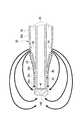
ここで、流出孔54と灌流液の流れに関する評価について説明する。本件発明者は、流出孔54の形状の変化によってチップ33の先端33aにおける灌流液の流れがどのように変化するのかを検証するための評価を行った。その評価結果を図6〜図8に概略図として示す。図6〜図8は、USハンドピース11をチップ33の先端33a側から見たときに、チップ33の先端33aの位置において灌流液が流れる範囲の評価結果を示している。  Here, the evaluation regarding theoutflow hole 54 and the flow of the perfusate will be described. The present inventor performed evaluation for verifying how the flow of the perfusate at thetip 33a of thetip 33 changes due to the change in the shape of theoutflow hole 54. The evaluation results are shown as schematic diagrams in FIGS. 6 to 8 show evaluation results of a range in which the perfusate flows at the position of thetip 33a of thetip 33 when theUS handpiece 11 is viewed from thetip 33a side of thetip 33. FIG.

そして、図6は流出孔54を本実施形態における細長形状(図3の形状)にした場合を示し、図7は流出孔54を変形例における偏平形状(図9の形状)にした場合を示し、図8は流出孔54を従来技術における丸穴形状(図11の形状)にした場合を示している。なお、図9に示す変形例における流出孔54は、本実施形態における細長形状よりもスリーブ22の軸方向に厚みを持たせた形状であって、スリーブ22(チップ33)の周方向を長手方向とする偏平形状(例えば、楕円形状)に形成されている。  FIG. 6 shows the case where theoutflow hole 54 has an elongated shape (the shape of FIG. 3) in the present embodiment, and FIG. 7 shows the case where theoutflow hole 54 has a flat shape (the shape of FIG. 9) in the modified example. FIG. 8 shows a case where theoutflow hole 54 has a round hole shape (the shape shown in FIG. 11) in the prior art. Theoutflow hole 54 in the modification shown in FIG. 9 has a shape that is thicker in the axial direction of thesleeve 22 than the elongated shape in the present embodiment, and the circumferential direction of the sleeve 22 (chip 33) is the longitudinal direction. It is formed in the flat shape (for example, elliptical shape).

そこで、図6〜図8に示す評価結果によると、流出孔54を丸穴形状に形成した場合には、図8に示すように、チップ33の先端33aにおいて、2つの流出孔54から流出した灌流液が流れる範囲が重なった。これは、流出孔54を丸穴形状に形成した場合には、チップ33の先端33aにおいて、灌流液がチップ33の周方向の狭い範囲に集中し易いので、灌流液の流れる範囲がチップ33の径方向の内側へ広がり易くなっていると考えられる。  Therefore, according to the evaluation results shown in FIGS. 6 to 8, when theoutflow hole 54 is formed in a round hole shape, as shown in FIG. 8, it flows out of the twooutflow holes 54 at thetip 33 a of thetip 33. The areas where the perfusate flowed overlapped. This is because when theoutflow hole 54 is formed in a round hole shape, the perfusate tends to concentrate in a narrow range in the circumferential direction of thetip 33 at thetip 33 a of thetip 33. It is thought that it is easy to spread inward in the radial direction.

これに対し、流出孔54を本実施形態における細長形状に形成した場合、すなわち、流出孔54をチップ33の後端側に凸の円弧状に形成した場合には、図6に示すように、チップ33の先端33aにおいて、2つの流出孔54から流出した灌流液が流れる範囲が重ならず、また、図面の上下方向に広がっている事が分かる。なお、2つの流出孔54から流出した灌流液が流れる範囲の間には、約3.0mmの間隔αが生じた。これは、チップ33の先端33aにおいて、灌流液がチップ33の周方向に広がってチップ33の先端33aの周囲を囲う様な形状となり易いので、灌流液の流れる範囲がチップ33の径方向の内側へ広がり難くなっていると考えられる。  On the other hand, when theoutflow hole 54 is formed in a slender shape in the present embodiment, that is, when theoutflow hole 54 is formed in a convex arc shape on the rear end side of thechip 33, as shown in FIG. It can be seen that at thetip 33a of thetip 33, the areas where the perfusate flowing out from the twooutflow holes 54 flows do not overlap and spread in the vertical direction of the drawing. Note that an interval α of about 3.0 mm was generated between the ranges in which the perfusate flowing out from the twooutflow holes 54 flows. This is because the perfusate tends to spread in the circumferential direction of thetip 33 and surround thetip 33a of thetip 33 at thetip 33a of thetip 33. It seems that it is difficult to spread.

なお、流出孔54を変形例における偏平形状にした場合においても、図7に示すように、チップ33の先端33aにおいて、2つの流出孔54から流出した灌流液が流れる範囲が重ならなかったが、図面の上下方向への広がりが小さい事が分かる。以上が、流出孔54と灌流液の流れに関する評価についての説明である。  Even when theoutflow hole 54 has a flat shape in the modification, as shown in FIG. 7, the flow ranges of the perfusate flowing out from the twooutflow holes 54 do not overlap at thetip 33 a of thetip 33. It can be seen that the vertical spread of the drawing is small. The above is the description about the evaluation regarding theoutflow hole 54 and the flow of the perfusate.

また、本実施形態においては、2つの流出孔54がチップ33の中心軸を中心にして対称に形成されている。このように2つの流出孔54が対称に形成されているので、2つの流出孔54から流出した灌流液は、チップ33の先端33aにおいて、チップ33の周方向に均等に流れて、チップ33の先端の周囲を均等に囲う様な形状となって吸引孔41から吸引され易くなる。また、流出孔54は複数形成されているので、チップ33の先端33aにおいて、チップ33の周方向における灌流液の流量の偏りが少なくなり、灌流液が集中して流れる部分が生じ難くなる。そのため、核100は、灌流液により囲まれてチップ33の先端33aから逃げ難くなる。このようにして、手術時において、核100を好適に吸引孔41から吸引して除去できる。  In the present embodiment, the twooutflow holes 54 are formed symmetrically about the central axis of thetip 33. Since the twooutflow holes 54 are formed symmetrically in this way, the perfusate that has flowed out of the twooutflow holes 54 flows evenly in the circumferential direction of thechip 33 at thetip 33a of thechip 33, and It becomes a shape that uniformly surrounds the periphery of the tip, and is easily sucked from thesuction hole 41. Further, since a plurality of outflow holes 54 are formed, the unevenness of the flow rate of the perfusate in the circumferential direction of thetip 33 is reduced at thetip 33a of thetip 33, and a portion where the perfusate flows concentratedly hardly occurs. Therefore, thenucleus 100 is surrounded by the perfusate and is difficult to escape from thetip 33a of thetip 33. In this way, thenucleus 100 can be suitably sucked and removed from thesuction hole 41 during the operation.

また、本実施形態においては、流出孔54は、チップ33を被覆するスリーブ22に形成されているので、チップ33の外周面33bからチップ33の径方向の外側に離れた位置に形成されている。そのため、灌流液は、チップ33から離れた位置から眼内に流出する。したがって、流出孔54から流出する灌流液は、図4において実線の矢印で示すように、眼内におけるチップ33から離れた位置を循環してチップ33の先端33a側に流れ易くなる。したがって、流出孔54からチップ33の近くを流れて先端33a側に流れる灌流液(図4において破線の矢印で示す灌流液)の量を減らすことができる。ゆえに、核100は、チップ33の近くを流れて先端33a側に流れる灌流液に押され難くなるので、チップ33の先端33aから逃げ難くなる。  In the present embodiment, theoutflow hole 54 is formed in thesleeve 22 that covers thechip 33, and thus is formed at a position away from the outerperipheral surface 33 b of thechip 33 to the outside in the radial direction of thechip 33. . Therefore, the perfusate flows out from the position away from thechip 33 into the eye. Therefore, the perfusate flowing out from theoutflow hole 54 circulates at a position away from thetip 33 in the eye and flows easily toward thetip 33 a side of thetip 33 as indicated by the solid line arrow in FIG. 4. Therefore, it is possible to reduce the amount of perfusate (perfusate indicated by a broken line arrow in FIG. 4) flowing from theoutflow hole 54 near thetip 33 to thetip 33a side. Therefore, since thenucleus 100 is less likely to be pushed by the perfusate flowing near thetip 33 and flowing toward thetip 33a, it is difficult to escape from thetip 33a of thetip 33.

また、流出孔54は、スリーブ22のテーパ部53に形成されており、スリーブ22の軸方向に対して傾いて形成されているので、流出孔54におけるチップ33の後端側から流出する灌流液は、チップ33の径方向(図4の上下方向)に向かって流出するだけではなく、チップ33の先端33a側の方向へ向かっても流出し易くなる。そのため、図4において実線の矢印で示すように、流出孔54におけるチップ33の後端側から流出する灌流液についても、眼内におけるチップ33から離れた位置を循環してチップ33の先端側に流れ易くなる。そのため、核100は、灌流液により囲まれてチップ33の先端33aから逃げ難くなる。このようにして、手術時において、核100を好適に吸引孔41から吸引して除去できる。  Further, since theoutflow hole 54 is formed in the taperedportion 53 of thesleeve 22 and is formed to be inclined with respect to the axial direction of thesleeve 22, the perfusate flowing out from the rear end side of thechip 33 in theoutflow hole 54. Does not only flow out in the radial direction of the chip 33 (vertical direction in FIG. 4), but also flows out in the direction toward thetip 33a of thechip 33. Therefore, as shown by the solid line arrow in FIG. 4, the perfusate flowing out from the rear end side of thetip 33 in theoutflow hole 54 also circulates at a position away from thetip 33 in the eye and moves to the tip end side of thetip 33. It becomes easy to flow. Therefore, thenucleus 100 is surrounded by the perfusate and is difficult to escape from thetip 33a of thetip 33. In this way, thenucleus 100 can be suitably sucked and removed from thesuction hole 41 during the operation.

また、本実施形態では、前記のように、2つの流出孔54がチップ33の中心軸を中心にして対称に形成されているが、例えば、図3に示すように、チップ33の先端33aにおける尖った部分である最先端部33cを下にして、チップ33とスリーブ22を側面から見たときに、2つの流出孔54は手前側と奥側に形成されている。すなわち、図3に示すように互いに直交するXYZ軸を規定し、中心軸Lに対してZ軸方向にチップ33の先端33aにおける最先端部33cを配置したときに、2つの流出孔54は、中心軸Lに対してY軸方向に形成されている。なお、X軸方向はチップ33の軸方向に相当し、Y軸方向とZ軸方向はチップ33の径方向に相当する。また、中心軸Lは、スリーブ22の中心軸であり、チップ33の中心軸であり、吸引孔41の中心軸でもある。  In the present embodiment, as described above, the twooutflow holes 54 are formed symmetrically about the central axis of thetip 33. For example, as shown in FIG. When thetip 33 and thesleeve 22 are viewed from the side with thetip 33c, which is a sharp part, facing down, the twooutflow holes 54 are formed on the near side and the far side. That is, when the XYZ axes orthogonal to each other are defined as shown in FIG. 3 and the mostdistal portion 33c of thetip 33a of thetip 33 is disposed in the Z-axis direction with respect to the central axis L, the twooutflow holes 54 are It is formed in the Y-axis direction with respect to the central axis L. The X-axis direction corresponds to the axial direction of thechip 33, and the Y-axis direction and the Z-axis direction correspond to the radial direction of thechip 33. The central axis L is the central axis of thesleeve 22, the central axis of thetip 33, and the central axis of thesuction hole 41.

そして、このように2つの流出孔54を形成することにより、図5に示すように、手術時にチップ33の先端33aにおける最先端部33cを下にしたときに、2つの流出孔54は、角膜101の内側に対向する上側と下側に配置されず、手前側と奥側に配置される。そのため、流出孔54から流出する灌流液は、角膜101の内側に当たり難い状態で、眼内に供給される。  Then, by forming the twooutflow holes 54 in this way, as shown in FIG. 5, when the mostdistal portion 33c of thetip 33a of thetip 33 is lowered at the time of surgery, the twooutflow holes 54 are formed in the cornea. It is not arranged on the upper side and the lower side facing the inner side of 101, but is arranged on the near side and the far side. Therefore, the perfusate flowing out from theoutflow hole 54 is supplied into the eye in a state where it is difficult to hit the inside of thecornea 101.

ところで、前記の図6〜図8に示す評価結果において、スリーブ22の軸方向についてのスリーブ22の先端22aから流出孔54までの距離D(図3や図9や図11参照)とチップ33の先端33aにおける灌流液の流れとの関係について着目する。なお、距離Dについて、図6の場合は約1.4mm、図7の場合は約1.2mm、図8の場合は約0.5mmであった。  Incidentally, in the evaluation results shown in FIGS. 6 to 8, the distance D (see FIGS. 3, 9, and 11) from thetip 22 a of thesleeve 22 to theoutflow hole 54 in the axial direction of thesleeve 22 and thetip 33. Attention is paid to the relationship with the flow of the perfusate at thetip 33a. The distance D was about 1.4 mm in the case of FIG. 6, about 1.2 mm in the case of FIG. 7, and about 0.5 mm in the case of FIG.

すると、図6〜図8に示す評価結果から、距離Dが大きいほど、チップ33の先端33aにおいて、2つの流出孔54から流出した灌流液が流れる範囲が重なり難くなった。その理由は、以下のとおりと考えられる。まず、流出孔54から出る灌流液は、チップ33の先端33a方向の外側へ角度を持って放出される。そして、距離Dが大きいほど、流出孔54とスリーブ22の中心軸(チップ33の中心軸)との距離が大きくなる。そうすると、距離Dが大きいほど、灌流液は、チップ33から離れた位置から流出するので、図4において実線の矢印で示すように、眼内におけるチップ33から離れた位置を循環してチップ33の先端33a側に流れ易くなる。そのため、距離Dが大きいほど、流出孔54からチップ33の近くを流れて先端33a側に流れる灌流液(図4において破線の矢印で示す灌流液)の量が減ると考えられる。そして、このように流出孔54からチップ33の近くを流れて先端33a側に流れる灌流液の量が減ると、チップ33の先端33aにおいて灌流液がチップ33の径方向の内側に流れ難くなるので、2つの流出孔54から流出した灌流液が流れる範囲が重なり難くなると考えられる。  Then, from the evaluation results shown in FIG. 6 to FIG. 8, as the distance D increases, the ranges in which the perfusate flowing out from the twooutflow holes 54 flows hardly overlap at thetip 33 a of thetip 33. The reason is considered as follows. First, the perfusate exiting from theoutflow hole 54 is discharged to the outside in the direction of thetip 33a of thetip 33 at an angle. As the distance D increases, the distance between theoutflow hole 54 and the central axis of the sleeve 22 (the central axis of the tip 33) increases. Then, as the distance D increases, the perfusate flows out from the position away from thechip 33, and therefore, as indicated by the solid line arrow in FIG. It becomes easy to flow to thetip 33a side. For this reason, it is considered that the larger the distance D, the smaller the amount of perfusate (perfusate indicated by the dashed arrow in FIG. 4) that flows from theoutflow hole 54 near thetip 33 and flows toward thetip 33a. If the amount of the perfusate flowing from theoutflow hole 54 near thetip 33 and flowing toward thetip 33a decreases, the perfusate hardly flows at thetip 33a of thetip 33 inward in the radial direction of thetip 33. It is considered that the ranges in which the perfusate flowing out from the twooutflow holes 54 flows are difficult to overlap.

そして、このように距離Dが大きいほど、チップ33の先端33aにおいて灌流液がチップ33の径方向の内側に流れ難くなるので、チップ33の先端33aに吸引された核100は、灌流液に押され難くなって、チップ33の先端33aから逃げ難くなると考えられる。そのため、距離Dが大きいほど、手術時において、核100を好適に吸引孔41から吸引して除去できると考えられる。  As the distance D is increased in this way, the perfusate hardly flows inward in the radial direction of thetip 33 at thetip 33a of thetip 33, so that thenucleus 100 sucked by thetip 33a of thetip 33 is pushed to the perfusate. It becomes difficult to escape from thetip 33a of thetip 33. Therefore, it is considered that the larger the distance D, the more preferably thenucleus 100 can be sucked and removed from thesuction hole 41 during the operation.

そこで、本実施形態では、スリーブ22の軸方向についてのスリーブ22の先端22aから流出孔54までの距離Dを大きくして、核100を好適に吸引孔41から吸引して除去できるようにする。本実施形態では、距離Dを、例えば0.8mm以上かつ2.0mm以下とする。すなわち、本実施形態では、流出孔54は、スリーブ22の先端22aから、例えば0.8mm以上かつ2.0mm以下の距離離れた位置に形成されている。  Therefore, in the present embodiment, the distance D from thetip 22a of thesleeve 22 to theoutflow hole 54 in the axial direction of thesleeve 22 is increased so that thenucleus 100 can be preferably sucked and removed from thesuction hole 41. In the present embodiment, the distance D is, for example, not less than 0.8 mm and not more than 2.0 mm. In other words, in this embodiment, theoutflow hole 54 is formed at a position away from thetip 22a of thesleeve 22 by a distance of, for example, 0.8 mm or more and 2.0 mm or less.

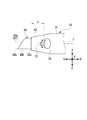
ここで、スリーブ22とチップ33の先端部分における各寸法の一例を図10に示す。なお、図10は、説明の便宜上、スリーブ22とチップ33の形状を模式的に示している。また、図10に示す数値の単位はmmである。  Here, an example of each dimension in thesleeve 22 and the tip portion of thetip 33 is shown in FIG. FIG. 10 schematically shows the shapes of thesleeve 22 and thetip 33 for convenience of explanation. Moreover, the unit of the numerical value shown in FIG. 10 is mm.

図10に示す例においては、吸引孔41の直径を0.7mm(半径rを0.35mm)、スリーブ22の先端22aの外径を1.1mm、スリーブ22の小径部51における中心軸Lに平行に形成されるフラット部55(テーパ部53よりも後端側の部分)の外径を1.8mm、スリーブ22のテーパ部53におけるスリーブ22の軸方向の長さを2.0mmとしている。  In the example shown in FIG. 10, the diameter of thesuction hole 41 is 0.7 mm (radius r is 0.35 mm), the outer diameter of thetip 22a of thesleeve 22 is 1.1 mm, and the central axis L of thesmall diameter portion 51 of thesleeve 22 is The outer diameter of the flat portion 55 (the portion on the rear end side with respect to the taper portion 53) formed in parallel is 1.8 mm, and the axial length of thesleeve 22 in thetaper portion 53 of thesleeve 22 is 2.0 mm.

そして、本実施形態によれば、流出孔54は、チップ33の周方向に沿って細長形状に形成され、かつ、複数形成されている。  And according to this embodiment, theoutflow hole 54 is formed in the elongate shape along the circumferential direction of the chip |tip 33, and multiple are formed.

これにより、灌流液はチップ33の周方向にカーテン状に広がって流出孔54から流出し易くなる。そのため、流出孔54から流出した灌流液は、チップ33の先端33aにおいて、チップ33の先端33aの周囲を囲う様な形状となる。また、流出孔54は複数形成されているので、チップ33の先端33aにおいて、チップ33の周方向の灌流液の流量の偏りが少なくなり、灌流液が集中して流れる部分が生じ難くなる。したがって、核100は、灌流液により囲まれて、チップ33の先端33aから逃げ難くなる。ゆえに、核100を好適に吸引孔41から吸引して除去できる。  Thereby, the perfusate spreads in a curtain shape in the circumferential direction of thetip 33 and easily flows out from theoutflow hole 54. Therefore, the perfusate that flows out from theoutflow hole 54 has a shape that surrounds the periphery of thetip 33 a of thetip 33 at thetip 33 a of thetip 33. In addition, since a plurality of outflow holes 54 are formed, the unevenness of the flow rate of the perfusate in the circumferential direction of thetip 33 is reduced at thetip 33a of thetip 33, and a portion where the perfusate flows concentratedly hardly occurs. Therefore, thenucleus 100 is surrounded by the perfusate and is difficult to escape from thetip 33a of thetip 33. Therefore, thenucleus 100 can be preferably removed by suction from thesuction hole 41.

また、本実施形態のUSハンドピース11は、シリコン樹脂等により形成され、チップ33の先端33aを突出させた状態でチップ33を被覆する筒状のスリーブ22を有する。このように軟性を有するスリーブ22によりチップ33を被覆しているので、スリーブ22の先端22aとチップ33の外周面33bとの密着部分における灌流液の漏れの発生が抑制される。  Further, theUS handpiece 11 of the present embodiment has acylindrical sleeve 22 that is formed of silicon resin or the like and covers thechip 33 with thetip 33a of thechip 33 protruding. Since thetip 33 is covered with thesoft sleeve 22 as described above, the occurrence of leakage of the perfusate at the close contact portion between thetip 22a of thesleeve 22 and the outerperipheral surface 33b of thetip 33 is suppressed.

そして、本実施形態では、このスリーブ22に流出孔54が形成されている。これにより、灌流液は、チップ33から離れた位置から眼内に流出する。そのため、流出孔54から流出する灌流液は、眼内におけるチップ33から離れた位置を循環してチップ33の先端33a側に流れ易くなり、チップ33の近くを流れ難くなる。したがって、核100は、灌流液に押され難くなるので、チップ33の先端33aから逃げ易くなる。ゆえに、核100を好適に吸引孔41から吸引して除去できる。  In this embodiment, anoutflow hole 54 is formed in thesleeve 22. Thereby, the perfusate flows into the eye from a position away from thetip 33. Therefore, the perfusate flowing out from theoutflow hole 54 circulates in a position away from thetip 33 in the eye and easily flows to thetip 33 a side of thetip 33, and hardly flows near thetip 33. Accordingly, thenucleus 100 is less likely to be pushed by the perfusate, and therefore easily escapes from thetip 33a of thetip 33. Therefore, thenucleus 100 can be preferably removed by suction from thesuction hole 41.

また、本実施形態のスリーブ22は、当該スリーブ22の先端22a側の部分に外径が徐々に大きくなるテーパ部53を備えている。これにより、手術時において術眼の切開創へのスリーブ22の侵入を行い易くなる。そして、本実施形態では、このテーパ部53に流出孔54が形成されている。これにより、流出孔54から流出する灌流液は、眼内におけるチップ33の近くに流れ易くなってしまうが、本実施形態によればチップ33の先端33aから灌流液は離れる。そのため、核100は、チップ33の先端33aから逃げ難くなる。したがって、核100を好適に吸引孔41から吸引して除去できる。  In addition, thesleeve 22 of the present embodiment includes a taperedportion 53 whose outer diameter gradually increases at a portion on thetip 22a side of thesleeve 22. This facilitates the penetration of thesleeve 22 into the surgical incision at the time of surgery. In this embodiment, anoutflow hole 54 is formed in the taperedportion 53. Thereby, the perfusate flowing out from theoutflow hole 54 easily flows near thetip 33 in the eye, but according to the present embodiment, the perfusate is separated from thetip 33a of thetip 33. Therefore, thenucleus 100 is difficult to escape from thetip 33a of thetip 33. Therefore, thenucleus 100 can be preferably removed by suction from thesuction hole 41.

また、本実施形態によれば、2つの流出孔54がチップ33の中心軸を中心にして対称に形成されている。これにより、2つの流出孔54から流出した灌流液は、チップ33の先端33aの周囲を均等に囲う様な形状となって吸引孔41から吸引され易くなる。そのため、核100は、灌流液により囲まれてチップ33の先端33aから逃げ難くなる。したがって、核100を好適に吸引孔41から吸引して除去できる。  Further, according to the present embodiment, the twooutflow holes 54 are formed symmetrically about the central axis of thechip 33. As a result, the perfusate that has flowed out of the twooutflow holes 54 has a shape that uniformly surrounds the periphery of thetip 33 a of thetip 33 and is easily sucked from thesuction hole 41. Therefore, thenucleus 100 is surrounded by the perfusate and is difficult to escape from thetip 33a of thetip 33. Therefore, thenucleus 100 can be preferably removed by suction from thesuction hole 41.

また、本実施形態によれば、流出孔54は、チップ33の後端側に凸の円弧状に形成されている。これにより、より効果的に、灌流液はチップ33の周方向にカーテン状に広がって流出孔54から流出し易くなる。  Further, according to the present embodiment, theoutflow hole 54 is formed in a convex arc shape on the rear end side of thechip 33. Thereby, the perfusate is more effectively spread in a curtain shape in the circumferential direction of thetip 33 and easily flows out from theoutflow hole 54.

また、本実施形態の流出孔54は、スリーブ22のテーパ部53に形成され、スリーブ22の先端22aから0.8mm以上離れた位置に形成されている。これにより、チップ33から離れた位置から灌流液を流出させることができる。そのため、流出孔54からチップ33の近くを流れてチップ33の先端側に向かって流れる灌流液(図4の破線で示すように流れる灌流液)の量が減少する。そのため、核100は灌流液に押され難くなるので、核100を好適に吸引孔41から吸引して除去できる。  Further, theoutflow hole 54 of the present embodiment is formed in the taperedportion 53 of thesleeve 22 and is formed at a position separated from thetip 22a of thesleeve 22 by 0.8 mm or more. Thereby, the perfusate can flow out from a position away from thechip 33. For this reason, the amount of perfusate flowing from theoutflow hole 54 near thetip 33 and flowing toward the tip end side of the tip 33 (perfusate flowing as shown by a broken line in FIG. 4) decreases. Therefore, since thenucleus 100 becomes difficult to be pushed by the perfusate, thenucleus 100 can be suitably sucked and removed from thesuction hole 41.

なお、本実施形態では、流出孔54は細長形状に形成されているが、細長形状として、楕円形、長方形、角が丸まった長方形、非対称に歪みが生じた楕円形なども考えられる。  In this embodiment, theoutflow hole 54 is formed in an elongated shape. However, as the elongated shape, an elliptical shape, a rectangular shape, a rectangular shape with rounded corners, an elliptical shape in which distortion is generated asymmetrically, and the like are also conceivable.

なお、図10に示すような各寸法値について、スリーブ22の軸方向についてのスリーブ22の先端22aから流出孔54までの距離Dを、例えば0.8mm以上とすると、流出孔54と中心軸Lとの距離δは約0.7mm以上になる。そのため、(流出孔54と中心軸Lとの距離δ)/(吸引孔41の半径r)=約2.0以上となる。  For each dimension value as shown in FIG. 10, assuming that the distance D from thetip 22a of thesleeve 22 to theoutflow hole 54 in the axial direction of thesleeve 22 is, for example, 0.8 mm or more, theoutflow hole 54 and the central axis L The distance δ is about 0.7 mm or more. Therefore, (distance δ betweenoutflow hole 54 and central axis L) / (radius r of suction hole 41) = about 2.0 or more.

なお、上記した実施の形態は単なる例示にすぎず、本開示を何ら限定するものではなく、その要旨を逸脱しない範囲内で種々の改良、変形が可能であることはもちろんである。  It should be noted that the above-described embodiment is merely an example, and does not limit the present disclosure in any way, and various improvements and modifications can be made without departing from the scope of the present invention.

1 超音波手術装置
11 USハンドピース
21 USハンドピース本体
22 スリーブ
22a 先端
31 振動子
32 ホーン
33 チップ
33a 先端
33c 最先端部
41 吸引孔
53 テーパ部
54 流出孔
61 灌流通路
71 中央部分
100 核
D 距離
L 中心軸
DESCRIPTION OFSYMBOLS 1Ultrasonic surgery apparatus 11US handpiece 21 US handpiecemain body 22Sleeve 22a Tip 31Vibrator 32Horn 33Tip 33a Tip 33c Mostadvanced part 41Suction hole 53Taper part 54Outflow hole 61Perfusion passage 71Central part 100 Core D Distance L Center axis

Claims (6)

Translated fromJapanese
眼組織を破砕する筒状のチップと、灌流液を眼内に流出させる流出孔と、前記チップの先端に形成され破砕した前記眼組織と前記眼内に流出させた前記灌流液とを吸引する吸引孔と、を有する手術器具において、
前記流出孔は、前記チップの周方向に沿って細長形状に形成され、かつ、複数形成されていること、
を特徴とする手術器具。
A cylindrical tip for crushing the eye tissue, an outflow hole for allowing the perfusate to flow into the eye, the crushed eye tissue formed at the tip of the tip, and the perfusate flowing into the eye are aspirated. A surgical instrument having a suction hole,
The outflow holes are formed in an elongated shape along the circumferential direction of the chip, and a plurality of the outflow holes are formed.
Surgical instrument characterized by.
請求項1の手術器具において、
前記チップの先端を突出させた状態で前記チップを被覆する筒状のスリーブを有し、
前記流出孔は、前記スリーブに形成されていること、
を特徴とする手術器具。
The surgical instrument of claim 1,
A cylindrical sleeve that covers the tip in a state where the tip of the tip protrudes;
The outflow hole is formed in the sleeve;
Surgical instrument characterized by.
請求項2の手術器具において、
前記スリーブは、当該スリーブの先端側の部分に外径が徐々に大きくなるテーパ部を備え、
前記流出孔は、前記テーパ部に形成されていること、
を特徴とする手術器具。
The surgical instrument of claim 2,
The sleeve includes a tapered portion with an outer diameter gradually increasing at a tip side portion of the sleeve,
The outflow hole is formed in the tapered portion;
Surgical instrument characterized by.
請求項1乃至3のいずれか1つの手術器具において、
2つの前記流出孔が前記チップの中心軸を中心にして対称に形成されていること、
を特徴とする手術器具。
The surgical instrument according to any one of claims 1 to 3,
The two outflow holes are formed symmetrically about the central axis of the tip;
Surgical instrument characterized by.
請求項1乃至4のいずれか1つの手術器具において、
前記流出孔は、前記チップの後端側に凸の円弧状に形成されていること、
を特徴とする手術器具。
The surgical instrument according to any one of claims 1 to 4,
The outflow hole is formed in a convex arc shape on the rear end side of the chip;
Surgical instrument characterized by.
眼組織を破砕するための筒状のチップと、灌流液を眼内に流出させるための流出孔と、前記チップの先端に形成され破砕した前記眼組織と前記眼内に流出させた前記灌流液とを吸引する吸引孔と、を有する手術器具において、
前記チップの先端を突出させた状態で前記チップを被覆する筒状のスリーブを有し、
前記スリーブは、当該スリーブの先端側の部分に外径が徐々に大きくなるテーパ部を備え、
前記流出孔は、前記テーパ部に形成され、前記スリーブの先端から0.8mm以上離れた位置に形成されていること、
を特徴とする手術器具。
A cylindrical tip for crushing the eye tissue, an outflow hole for allowing the perfusate to flow into the eye, the crushing eye tissue formed at the tip of the tip, and the perfusate flowing out into the eye In a surgical instrument having a suction hole for sucking
A cylindrical sleeve that covers the tip in a state where the tip of the tip protrudes;
The sleeve includes a tapered portion with an outer diameter gradually increasing at a tip side portion of the sleeve,
The outflow hole is formed in the tapered portion, and is formed at a position away from the tip of the sleeve by 0.8 mm or more;
Surgical instrument characterized by.
JP2016089893A2016-04-272016-04-27Surgical instrumentPendingJP2017196196A (en)

Priority Applications (1)

Application NumberPriority DateFiling DateTitle
JP2016089893AJP2017196196A (en)2016-04-272016-04-27Surgical instrument

Applications Claiming Priority (1)

Application NumberPriority DateFiling DateTitle
JP2016089893AJP2017196196A (en)2016-04-272016-04-27Surgical instrument

Publications (2)

Publication NumberPublication Date
JP2017196196Atrue JP2017196196A (en)2017-11-02
JP2017196196A5 JP2017196196A5 (en)2019-04-25

Family

ID=60236821

Family Applications (1)

Application NumberTitlePriority DateFiling Date
JP2016089893APendingJP2017196196A (en)2016-04-272016-04-27Surgical instrument

Country Status (1)

CountryLink
JP (1)JP2017196196A (en)

Citations (7)

* Cited by examiner, † Cited by third party
Publication numberPriority datePublication dateAssigneeTitle
US5257988A (en)*1991-07-191993-11-02L'esperance Medical Technologies, Inc.Apparatus for phacoemulsifying cataractous-lens tissue within a protected environment
US6159175A (en)*1995-06-022000-12-12Surgical Design CorporationPhacoemulsification handpiece, sleeve, and tip
JP2006000647A (en)*2004-06-142006-01-05Alcon IncTip part for handpiece
US20110172590A1 (en)*2010-01-082011-07-14Takayuki AkahoshiInfusion Sleeve With Distendable Port
JP2012512713A (en)*2008-12-182012-06-07アルコン リサーチ, リミテッド Perfusion sleeve for phacoemulsification with buttock
US20120245562A1 (en)*2011-03-222012-09-27Becton, Dickinson And CompanyCatheter having a spiral slit
US20130102955A1 (en)*2011-09-262013-04-25Richard S. KOPLINApparatus and method for performing phacoemulsification

Patent Citations (7)

* Cited by examiner, † Cited by third party
Publication numberPriority datePublication dateAssigneeTitle
US5257988A (en)*1991-07-191993-11-02L'esperance Medical Technologies, Inc.Apparatus for phacoemulsifying cataractous-lens tissue within a protected environment
US6159175A (en)*1995-06-022000-12-12Surgical Design CorporationPhacoemulsification handpiece, sleeve, and tip
JP2006000647A (en)*2004-06-142006-01-05Alcon IncTip part for handpiece
JP2012512713A (en)*2008-12-182012-06-07アルコン リサーチ, リミテッド Perfusion sleeve for phacoemulsification with buttock
US20110172590A1 (en)*2010-01-082011-07-14Takayuki AkahoshiInfusion Sleeve With Distendable Port
US20120245562A1 (en)*2011-03-222012-09-27Becton, Dickinson And CompanyCatheter having a spiral slit
US20130102955A1 (en)*2011-09-262013-04-25Richard S. KOPLINApparatus and method for performing phacoemulsification

Similar Documents

PublicationPublication DateTitle
CA2745344C (en)Variable frequency phacoemulsification handpiece
US9962288B2 (en)Active acoustic streaming in hand piece for occlusion surge mitigation
US7967799B2 (en)Liquefaction handpiece tip
US6428508B1 (en)Pulsed vacuum cataract removal system
US8308735B2 (en)Phacoemulsification tip with internal oriented structures
US20120172786A1 (en)Multi-sleeved surgical ultrasonic vibrating tool suited for phacoemulsification in a manner that prevents thermal injury to ocular tissue
US8784357B2 (en)Phacoemulsification hand piece with two independent transducers
JP2002153500A (en)Liquefaction crushing handpiece and its tip
JP2011530328A (en) Offset ultrasonic handpiece
JP6023191B2 (en) Vacuum level control of power for phacoemulsification handpiece
JP2009095662A (en)Handpiece for ultrasonic surgery and chip for ultrasonic surgery
EP1388331B1 (en)Liquefaction handpiece tip
GilgerPhacoemulsification: technology and fundamentals
WO2006101717A2 (en)Phacoemulsification tip
WO2006096335A2 (en)Phacoemulsification tip
WO2005032439A1 (en)Phacoemulsification needle
JP2007296364A (en)Phacoemulsification tip
JP2017196196A (en)Surgical instrument
JP3791987B2 (en) Ultrasonic surgical device
JP6295567B2 (en) Ophthalmic Surgery Ultrasound Chip
JP2020018626A (en)Ophthalmic operation device
JP5685295B2 (en) Surgical tools
JP2019084168A (en)Ultrasound surgical tip
JPH11192232A (en)Ultrasonic operation tip and ultrasonic operation device with the same
JP4003949B2 (en) Ultrasonic surgical chip and ultrasonic surgical apparatus including the same

Legal Events

DateCodeTitleDescription
A521Request for written amendment filed

Free format text:JAPANESE INTERMEDIATE CODE: A523

Effective date:20190312

A621Written request for application examination

Free format text:JAPANESE INTERMEDIATE CODE: A621

Effective date:20190312

A131Notification of reasons for refusal

Free format text:JAPANESE INTERMEDIATE CODE: A131

Effective date:20191119

A977Report on retrieval

Free format text:JAPANESE INTERMEDIATE CODE: A971007

Effective date:20191115

A521Request for written amendment filed

Free format text:JAPANESE INTERMEDIATE CODE: A523

Effective date:20200116

A131Notification of reasons for refusal

Free format text:JAPANESE INTERMEDIATE CODE: A131

Effective date:20200630

A521Request for written amendment filed

Free format text:JAPANESE INTERMEDIATE CODE: A523

Effective date:20200819

A02Decision of refusal

Free format text:JAPANESE INTERMEDIATE CODE: A02

Effective date:20210119


[8]ページ先頭

©2009-2025 Movatter.jp