JP2017193284A - Acoustic device shake correction device - Google Patents
Acoustic device shake correction deviceDownload PDFInfo
- Publication number
- JP2017193284A JP2017193284AJP2016085458AJP2016085458AJP2017193284AJP 2017193284 AJP2017193284 AJP 2017193284AJP 2016085458 AJP2016085458 AJP 2016085458AJP 2016085458 AJP2016085458 AJP 2016085458AJP 2017193284 AJP2017193284 AJP 2017193284A
- Authority
- JP
- Japan
- Prior art keywords
- frame body
- heave
- acoustic device
- pitch
- roll
- Prior art date
- Legal status (The legal status is an assumption and is not a legal conclusion. Google has not performed a legal analysis and makes no representation as to the accuracy of the status listed.)
- Granted
Links
Images


Landscapes
- Measurement Of Velocity Or Position Using Acoustic Or Ultrasonic Waves (AREA)
Abstract
Translated fromJapaneseDescription
Translated fromJapanese本発明は、船に取り付けられた音響装置が船の動揺に伴って動揺するのを抑制するために、音響装置の動揺を補正する、音響装置動揺補正装置に関する。 The present invention relates to an acoustic device fluctuation correcting device that corrects the vibration of an acoustic device in order to suppress the acoustic device attached to the ship from being shaken as the boat shakes.
図10に示されるように、海上の船10と海中のビークル90との間のデータの送受信は、一般に、各々に取り付けられた同じ音響装置9によって行われている。図10は、船10の底に取り付けられている音響装置9から音波が発信されている状態を、示している。図10では、船10は、波浪の影響を受けておらず、すなわち、静止状態にあり、船底101の音響装置9は、真下を向いており、よって、音響装置9から発信されている音波の伝播領域Wも真下に向いている。 As shown in FIG. 10, transmission / reception of data between the
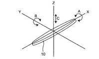
ところで、図11に示されるように、船10は、波浪の影響を受けると、X軸回りのロール動作方向A、Y軸回りのピッチ動作方向B、Z軸回りのヒーブ動作方向Cに、動揺する。船10が動揺すると、船底に固定されている音響装置9も、同様に動揺する。 By the way, as shown in FIG. 11, when the
そして、例えば、船10すなわち音響装置9がピッチ動作方向に動揺した場合には、図12に示されるように、音響装置9から発信されている音波の伝播領域Wが真下からずれた方向に向き、ビークル90での受信確率が低下する。船10がロール動作方向に動揺した場合も、同様である。また、船10がヒーブ動作方向に動揺した場合には、ドップラー効果によって音速が変化し、周波数も変化するので、これによっても、ビークル90での受信確率が低下する。 For example, when the
このような通信確率の低下を回避するために、特許文献1のように、音響装置9の動揺をプログラムによって補正する技術が提案されている。 In order to avoid such a decrease in communication probability, a technique for correcting the fluctuation of the
しかるに、一方では、音響装置9の動揺を機械的に補正する技術も、望まれている。機械的補正であれば、あらゆる種類の船に容易に適用できるからである。 However, on the other hand, a technique for mechanically correcting the vibration of the
本発明は、機械式の音響装置動揺補正装置を提供することを、目的としている。 An object of the present invention is to provide a mechanical acoustic device fluctuation correcting device.
本発明は、船に取り付けられた音響装置が船の動揺に伴って動揺するのを抑制するために、前記音響装置の動揺を補正する、音響装置動揺補正装置であって、船に固定された第1フレーム体と、前記第1フレーム体に支持された第2フレーム体と、前記第2フレーム体に支持された第3フレーム体と、を備えており、前記第3フレーム体は、前記音響装置を支持しており、船が動揺した際における、前記音響装置の、ピッチ動作方向の角度又は角速度又は角加速度と、ロール動作方向の角度又は角速度又は角加速度と、ヒーブ動作方向の速度又は加速度と、をそれぞれ検出する、姿勢センサと、前記音響装置を、前記第3フレーム体に対してピッチ動作させる、ピッチ駆動機構と、前記第3フレーム体を、前記音響装置と共に、前記第2フレーム体に対してロール動作させる、ロール駆動機構と、前記第2フレーム体を、前記第3フレーム体及び前記音響装置と共に、第1フレーム体に対してヒーブ動作させる、ヒーブ駆動機構と、前記ピッチ駆動機構、前記ロール駆動機構、及び前記ヒーブ駆動機構を、制御する、制御部と、を更に備えており、前記制御部は、前記姿勢センサの検出値に基づいて、前記音響装置が初期設定方向を向くように前記ピッチ駆動機構及び前記ロール駆動機構を制御するとともに前記音響装置のヒーブ動作方向の速度が所定値以下となるように前記ヒーブ駆動機構を制御するようになっている、ことを特徴としている。 The present invention is an acoustic device fluctuation correction device that corrects the vibration of the acoustic device in order to prevent the acoustic device attached to the ship from being shaken with the vibration of the ship, and is fixed to the ship. A first frame body, a second frame body supported by the first frame body, and a third frame body supported by the second frame body, wherein the third frame body includes the sound An angle or angular velocity or angular acceleration in the pitch motion direction, an angle or angular velocity or angular acceleration in the roll motion direction, and a velocity or acceleration in the heave motion direction of the acoustic device when the ship is shaken while supporting the device Detecting a posture sensor, and a pitch driving mechanism for causing the acoustic device to perform a pitch operation with respect to the third frame body, and the third frame body together with the acoustic device. A roll driving mechanism for performing a roll operation on the frame body, a heave driving mechanism for causing the second frame body to perform a heave operation on the first frame body together with the third frame body and the acoustic device, and the pitch. A control unit that controls the drive mechanism, the roll drive mechanism, and the heave drive mechanism, wherein the control unit is configured so that the acoustic device is in an initial setting direction based on a detection value of the attitude sensor. The pitch drive mechanism and the roll drive mechanism are controlled so as to face, and the heave drive mechanism is controlled so that the speed of the sound device in the heave operation direction is a predetermined value or less. It is said.
なお、音響装置の「初期設定方向」とは、平水中において音響装置から対象物への音波の伝播を最も良好に行うことができる場合の、音響装置の向いている方向である。例えば、音響装置が船底に取り付けられた場合には、初期設定方向は「真下」である。 The “initial setting direction” of the acoustic device is a direction in which the acoustic device is facing when propagation of sound waves from the acoustic device to an object can be best performed in plain water. For example, when the acoustic device is attached to the ship bottom, the initial setting direction is “just below”.
本発明は、更に、任意に、次の構成を採用するのが好ましい。
(a)前記ピッチ駆動機構は、前記第3フレーム体が前記音響装置をピッチ動作可能に支持するための、ピッチ動作軸と、前記音響装置に固定されたピッチ用電動機と、前記ピッチ用電動機の回転を前記ピッチ動作軸に伝えるピッチ用伝達機構と、を備えており、前記制御部は、前記ピッチ用電動機の回転を制御するようになっている。The present invention preferably further adopts the following configuration arbitrarily.
(A) The pitch drive mechanism includes a pitch operation shaft for the third frame body to support the acoustic device so as to perform a pitch operation, a pitch motor fixed to the acoustic device, and the pitch motor. A transmission mechanism for transmitting the rotation to the pitch operation axis, and the control unit controls the rotation of the pitch motor.
(b)前記ロール駆動機構は、前記第2フレーム体が前記第3フレーム体をロール動作可能に支持するための、ロール動作軸と、前記第2フレーム体に固定されたロール用電動機と、前記ロール用電動機の回転を前記ロール動作軸に伝えるロール用伝達機構と、を備えており、前記制御部は、前記ロール用電動機の回転を制御するようになっている。(B) The roll driving mechanism includes a roll operating shaft for the second frame body to support the third frame body so as to be able to perform a roll operation, a roll electric motor fixed to the second frame body, A roll transmission mechanism that transmits the rotation of the roll motor to the roll operation shaft, and the control unit controls the rotation of the roll motor.
(c)前記ヒーブ駆動機構は、前記第1フレーム体が前記第2フレーム体をヒーブ動作可能に支持するための、ヒーブガイド軸と、前記第1フレーム体に固定されたヒーブ用電動機と、前記ヒーブ用電動機の回転をヒーブ動作に変換して前記第2フレーム体に伝える、ヒーブ用伝達機構と、を備えており、前記制御部は、前記ヒーブ用電動機の回転を制御するようになっている。(C) The heave drive mechanism includes a heave guide shaft for supporting the second frame body so that the first frame body can perform a heave operation, a heave motor fixed to the first frame body, A heave transmission mechanism that converts the rotation of the heave motor into a heave operation and transmits it to the second frame body, and the control unit controls the rotation of the heave motor. .
本発明においては、音響装置が船の動揺に伴って動揺しようとした時に、ピッチ駆動機構及びロール駆動機構を制御して、音響装置を初期設定方向に向けることができるとともに、ヒーブ駆動機構を制御して、音響装置のヒーブ動作方向の速度を所定値以下に抑制できる。したがって、音響装置から発信されている音波の伝播領域が初期設定方向からずれた方向に向くのを、防止できるとともに、ドップラー効果による音波の周波数の変化を抑制できる。よって、本発明によれば、船の動揺によって音響装置の通信確率が低下するのを、防止できる。 In the present invention, when the acoustic device tries to shake as the ship shakes, the pitch drive mechanism and the roll drive mechanism can be controlled so that the acoustic device can be directed in the initial setting direction and the heave drive mechanism can be controlled. Thus, the speed of the sound device in the heave operation direction can be suppressed to a predetermined value or less. Therefore, it is possible to prevent the propagation region of the sound wave transmitted from the acoustic device from being shifted from the initial setting direction, and to suppress the change in the frequency of the sound wave due to the Doppler effect. Therefore, according to this invention, it can prevent that the communication probability of an audio equipment falls by ship's shaking.
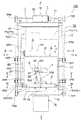
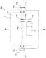
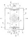
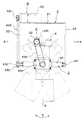
図1は本発明の一実施形態の音響装置動揺補正装置100の正面図であり、図2は図1のII矢視図であり、図3は図1のIII矢視図であり、図4は図1のIV矢視図であり、図5は図1のV−V断面図であり、図6は図1のVI−VI断面図である。図7は制御機構のブロック図である。 1 is a front view of an acoustic device
装置100は、音響装置9を支持した状態で船底101に取り付けて用いられ、音響装置9が船10の動揺に伴って動揺するのを抑制するために、音響装置9の動揺を補正する。音響装置9は、初期設定方向を向いた状態で装置100に支持されており、ここでは、装置100は船底101に取り付けられているので、音響装置9は真下を向いた状態で装置100に支持されている。装置100は、第1フレーム体1、第2フレーム体2、第3フレーム体3、姿勢センサ4、ピッチ駆動機構5、ロール駆動機構6、ヒーブ駆動機構7、及び制御部8を、備えている。音響装置9は、第3フレーム体3に支持されている。なお、装置100の正面は、船10の側面側に向いている。 The
[第1フレーム体]
第1フレーム体1は、平面視矩形の直方体形状を有している。第1フレーム体1は、天板11、右側板12、左側板13、前板14、背板15、及び底板16を、有している。右側板12、左側板13、前板14、背板15、及び底板16は、それぞれ、中央に大きな開口121、131、141、151、161を、有している。すなわち、天板11以外の各板12、13、14、15、16は、実質的には、それぞれ、周囲枠で構成されている。そして、第1フレーム体1は、上部にて、船底101に対して垂直となるように、船底101に固定されている。[First frame body]
The
[第2フレーム体]
第2フレーム体2は、第1フレーム体1の内部に配置されている。第2フレーム体2は、天板21、右側板22、及び左側板23を、有している。すなわち、第2フレーム体2は、前後方向に開通している。[Second frame body]
The
[第3フレーム体]
第3フレーム体3は、第2フレーム体2の内部に配置されている。第3フレーム体3は、第2フレーム体2の底板を構成するように配置された枠体である。すなわち、第3フレーム体3は、前枠31、背枠32、右枠33、及び左枠34を、有している。[Third frame body]
The
[ピッチ駆動機構]
ピッチ駆動機構5は、ピッチ動作軸51、ピッチ用電動機52、及びピッチ用伝達機構53を、有している。[Pitch drive mechanism]
The
ピッチ動作軸51は、図6に示されるように、音響装置9を第3フレーム体3に対してピッチ動作可能に支持している。ピッチ動作軸51は、水平に伸びており、前枠31にピッチ動作可能に挿通されている前軸部511と、背枠32にピッチ動作可能に挿通されている後軸部512と、からなっている。前軸部511及び後軸部512は、音響装置9の縦方向中央部に固定されている。 As shown in FIG. 6, the
ピッチ用電動機52は、サーボ電動機であり、音響装置9の頂面91上に固定されている。 The
ピッチ用伝達機構53は、ピッチ用電動機52の回転軸に固定された第1スプロケット531と、ピッチ動作軸51の前軸部511に固定された第2スプロケット532と、両スプロケット531、532に掛け渡された歯付きベルト533と、を有している。 The
これにより、ピッチ用電動機52が作動すると、第1スプロケット531、歯付きベルト533、及び第2スプロケット532を介して、ピッチ動作軸51が回転し、それに伴って、音響装置9が第3フレーム体3に対してピッチ動作するようになっている。 Accordingly, when the
[ロール駆動機構]
ロール駆動機構6は、ロール動作軸61、ロール用電動機62、及びロール用伝達機構63を、有している。ロール動作軸61は、ピッチ動作軸51に対して同一平面内で直交して且つ水平に伸びており、第2フレーム体2の右側板22にロール動作可能に挿通されている右軸部611と、第2フレーム体2の左側板23にロール動作可能に挿通されている左軸部612と、からなっている。右軸部611及び左軸部612は、それぞれ、第3フレーム体3の右枠33及び左枠34の前後方向中央部に、固定されている。[Roll drive mechanism]
The
ロール用電動機62は、サーボ電動機であり、第2フレーム体2の天板21上に固定されている。 The
ロール用伝達機構63は、ロール用電動機62の回転軸に固定された第1スプロケット631と、ロール動作軸62の左軸部612に固定された第2スプロケット632と、両スプロケット631、632に掛け渡された歯付きベルト633と、を有している。なお、第2スプロケット632は、第2フレーム体2の外部且つ第1フレーム体1の内部に、位置している。 The
これにより、ロール用電動機62が作動すると、第1スプロケット631、歯付きベルト633、及び第2スプロケット632を介して、ロール動作軸61が回転し、それに伴って、第3フレーム体3が、音響装置9と共に、第2フレーム体2に対してロール動作するようになっている。 As a result, when the
[ヒーブ駆動機構]
ヒーブ駆動機構7は、ヒーブガイド軸71、ヒーブ用電動機72、及びヒーブ用伝達機構73を、有している。ヒーブガイド軸71は、第1フレーム体1の右側板12の前後方向中央部に、上下方向に延びて固定されている、右ガイド軸711と、第1フレーム体1の左側板13の前後方向中央部に、上下方向に延びて固定されている、左ガイド軸712と、を有している。右ガイド軸711と左ガイド軸712とは、平面視において対向した位置に配置されている。そして、両ガイド軸711、712には、第2フレーム体2がアーム241、242、243、244を介して、摺動自在に、支持されている。すなわち、第2フレーム体2は、第1フレーム体1に対して、ヒーブガイド軸71に沿ってヒーブ動作可能となっている。なお、アーム241、242は、それぞれ、第2フレーム体2の右側板22の上と下の位置に、設けられており、アーム243、244は、それぞれ、第2フレーム体2の左側板23の上と下の位置に、設けられている。[Heave drive mechanism]
The heave drive mechanism 7 includes a
ヒーブ用電動機72は、サーボ電動機であり、第1フレーム体1の天板11上に固定されている。 The
ヒーブ用伝達機構73は、第1スプロケット731、伝達軸732、第2スプロケット733、第1歯付きベルト734、第3スプロケット735、第4スプロケット736、第5スプロケット737、第6スプロケット738、第2歯付きベルト739、及び第3歯付きベルト740を、有している。第1スプロケット731は、ヒーブ用電動機72の回転軸に固定されている。伝達軸732は、第1フレーム体1の天板11上に、回転自在に且つ左右方向に延びて、固定されている。第2スプロケット733は、第1スプロケット731に対して前後方向で対向するように、伝達軸732に固定されている。第1歯付きベルト734は、第1スプロケット731と第2スプロケット733とに掛け渡されている。第3スプロケット735及び第4スプロケット736は、それぞれ、伝達軸732の右端及び左端に、固定されている。第5スプロケット737は、第3スプロケット735に対して上下方向で対向するように、右側板12の下端又は底板16の右端面に、回転自在に固定されている。第6スプロケット738は、第4スプロケット736に対して上下方向で対向するように、左側板13の下端又は底板16の左端面に、回転自在に固定されている。第2歯付きベルト739は、第3スプロケット735と第5スプロケット737とに掛け渡されている。第3歯付きベルト740は、第4スプロケット736と第6スプロケット738とに掛け渡されている。そして、アーム241、242は、第2歯付きベルト739に固定されており、アーム243、244は、第3歯付きベルト740に固定されている。 The
これにより、ヒーブ用電動機72が作動すると、第1スプロケット731、第1歯付きベルト734、第2スプロケット733、伝達軸732、第3スプロケット735、及び第4スプロケット736を介して、第2歯付きベルト739及び第3歯付きベルト740が回転移動し、それに伴って、第2フレーム体2が、音響装置9及び第3フレーム体3と共に、ヒーブ動作するようになっている。 As a result, when the
[姿勢センサ]
姿勢センサ4は、音響装置9の頂面91に固定されている。姿勢センサ4は、船10が動揺した際における、音響装置9の、ピッチ動作方向の角度又は角速度又は角加速度と、ロール動作方向の角度又は角速度又は角加速度と、ヒーブ動作方向の速度又は加速度と、をそれぞれ検出するようになっている。[Attitude sensor]
The
[制御部]
制御部8は、図7に示されるように、姿勢センサ4の検出値に基づいて、音響装置9が真下を向くようにピッチ駆動機構5及びロール駆動機構6を制御するとともに音響装置9のヒーブ動作方向の速度が所定値V以下となるようにヒーブ駆動機構7を制御するようになっている。具体的には、制御部8は、ピッチ用電動機52、ロール用電動機62、及びヒーブ用電動機72を、サーボ制御するようになっている。なお、ヒーブ駆動機構7の制御における「所定値V」は、その速度を超えると音響装置9がドップラー効果の影響を排除できなくなる速度である。制御部8は、CPU、ROM、RAM等により、実現されている。[Control unit]
As shown in FIG. 7, the
[作動]
次に、前記構成の装置100の作動について、説明する。[Operation]
Next, the operation of the
装置100は、第1フレーム体1の上部にて、船底101に対して垂直となるように、船底101に固定されて、用いられる。そして、船底101に固定された装置100において、装置100に支持されている音響装置9は、船10が波浪の影響を受けていない状態では、真下を向いている。 The
そして、船10が波浪の影響を受けて動揺すると、装置100は次のように作動する。 When the
まず、姿勢センサ4が、音響装置9の、ピッチ動作方向Bの角度又は角速度又は角加速度と、ロール動作方向Aの角度又は角速度又は角加速度と、ヒーブ動作方向Cの速度又は加速度と、をそれぞれ検出する(図11参照)。 First, the
次に、制御部8が、姿勢センサ4の検出値に基づいて、ピッチ用電動機52、ロール用電動機62、及びヒーブ用電動機72を、サーボ制御する。具体的には、次のとおりである。 Next, the
(a)ピッチ変化量演算部811が、ピッチ動作方向Bの前記検出値に基づいて、音響装置9のピッチ動作方向Bにおける角度の変化量を求める。次に、ピッチ補正量演算部812が、音響装置9をピッチ動作方向Bにおいて下に向けるのに必要な角度の補正量を求める。次に、ピッチ補正指示部813が、当該補正量を実行するようにピッチ用電動機52を制御する。(A) The pitch change
そして、ピッチ用電動機52が、制御部8による制御によって回転すると、図8に示されるように、第1スプロケット531、歯付きベルト533、及び第2スプロケット532を経て、ピッチ動作軸51が回転し、それによって、音響装置9がピッチ動作方向Bに動揺する。この動揺量は、船10の動揺に伴ってピッチ動作方向Bに動揺しようとした音響装置9が、ピッチ動作方向において下を向くようになる量である。 Then, when the
(b)ロール変化量演算部821が、ロール動作方向Aの前記検出値に基づいて、音響装置9のロール動作方向Cにおける角度の変化量を求める。次に、ロール補正量演算部822が、音響装置9をロール動作方向Aにおいて下に向けるのに必要な角度の補正量を求める。次に、ロール補正指示部823が、当該補正量を実行するようにロール用電動機62を制御する。(B) The roll change
そして、ロール用電動機62が、制御部8による制御によって回転すると、図9に示されるように、第1スプロケット631、歯付きベルト633、及び第2スプロケット632を経て、ロール動作軸61が回転し、それによって、音響装置9がロール動作方向Aに動揺する。この動揺量は、船10の動揺に伴ってロール動作方向に動揺しようとした音響装置9が、ロール動作方向において下を向くようになる量である。 Then, when the
(c)ヒーブ変化量演算部831が、ヒーブ動作方向Cの前記検出値に基づいて、音響装置9のヒーブ動作方向Cにおける速度の変化量を求める。次に、ヒーブ補正量演算部832が、音響装置9のヒーブ動作方向Cにおける速度が所定値V以下となるのに必要な速度の補正量を求める。なお、「所定値V以下」は、ドップラー効果による音波の周波数の変化を抑制できる値である。そして、ヒーブ補正指示部833が、当該補正量を実行するようにヒーブ用電動機72を制御する。(C) The heave change
そして、ヒーブ用電動機72が、制御部8による制御によって回転すると、第1スプロケット731、第1歯付きベルト734、及び第2スプロケット733を介して、伝達軸732が回転し、それによって、第3スプロケット735、第2歯付きベルト739、及び第5スプロケット737が回転し、また、第4スプロケット736、第3歯付きベルト740、及び第6スプロケット738が回転する。その結果、第2歯付きベルト739及び第3歯付きベルト740がヒーブ動作方向Cに移動し、それに伴って、第2フレーム体2が、音響装置9及び第3フレーム体3と共に、第1フレーム体1に対して、ヒーブ動作方向Cに移動する。このときの第2フレーム体2の移動の速度は、船10の動揺に伴ってヒーブ動作方向Cに動揺しようとした音響装置9の速度が所定値V以下となるような値に、制御されている。 Then, when the
[効果]
前記構成の装置100によれば、音響装置9が船10の動揺に伴って動揺しようとした時に、ピッチ駆動機構5及びロール駆動機構6を制御して、音響装置9を真下すなわち初期設定方向に向けることができるとともに、ヒーブ駆動機構7を制御して、音響装置9のヒーブ動作方向Cの速度を所定値V以下に抑制できる。したがって、音響装置9から発信されている音波の伝播領域Wが真下からずれた方向に向くのを、防止できるとともに、ドップラー効果による音波の周波数の変化を抑制できる。よって、前記構成の装置100によれば、船10の動揺によって音響装置9の通信確率が低下するのを、防止できる。[effect]
According to the
しかも、ヒーブ駆動機構6は、位置の補正を行っているのではなく、ヒーブ動作方向Cの速度を所定値V以下に制御することを行っている。それ故、前記構成の装置100によれば、ヒーブ駆動機構6の小型化を図ることができる。 Moreover, the
[変形例]
(1)ヒーブ用伝達機構73においては、台形ねじ又はボールねじ等を用いて、ヒーブ用電動機72の回転をヒーブ動作に変換してもよい。
(2)装置100は、船底に限らず、船側に、取り付けられてもよい。[Modification]
(1) In the
(2) The
本発明の音響装置動揺補正装置は、船の動揺によって音響装置の通信確率が低下するのを、防止できるので、産業上の利用価値が大である。 The acoustic apparatus fluctuation correcting apparatus of the present invention can prevent the communication probability of the acoustic apparatus from being lowered due to the fluctuation of the ship, and thus has great industrial utility value.
10 船 101 船底 100 音響装置動揺補正装置 1 第1フレーム体
2 第2フレーム体 3 第3フレーム体 4 姿勢センサ 5 ピッチ駆動機構
51 ピッチ動作軸 52 ピッチ用電動機 53 ピッチ用伝達機構
6 ロール駆動機構 61 ロール動作軸 62 ロール用電動機
63 ロール用伝達機構 7 ヒーブ駆動機構 71 ヒーブガイド軸
72 ヒーブ用電動機 73 ヒーブ用伝達機構 8 制御部 9 音響装置DESCRIPTION OF
Claims (4)
Translated fromJapanese船に固定された第1フレーム体と、
前記第1フレーム体に支持された第2フレーム体と、
前記第2フレーム体に支持された第3フレーム体と、
を備えており、
前記第3フレーム体は、前記音響装置を支持しており、
船が動揺した際における、前記音響装置の、ピッチ動作方向の角度又は角速度又は角加速度と、ロール動作方向の角度又は角速度又は角加速度と、ヒーブ動作方向の速度又は加速度と、をそれぞれ検出する、姿勢センサと、
前記音響装置を、前記第3フレーム体に対してピッチ動作させる、ピッチ駆動機構と、
前記第3フレーム体を、前記音響装置と共に、前記第2フレーム体に対してロール動作させる、ロール駆動機構と、
前記第2フレーム体を、前記第3フレーム体及び前記音響装置と共に、第1フレーム体に対してヒーブ動作させる、ヒーブ駆動機構と、
前記ピッチ駆動機構、前記ロール駆動機構、及び前記ヒーブ駆動機構を、制御する、制御部と、
を更に備えており、
前記制御部は、前記姿勢センサの検出値に基づいて、前記音響装置が初期設定方向を向くように前記ピッチ駆動機構及び前記ロール駆動機構を制御するとともに前記音響装置のヒーブ動作方向の速度が所定値以下となるように前記ヒーブ駆動機構を制御するようになっている、
ことを特徴とする音響装置動揺補正装置。An acoustic device fluctuation correction device that corrects the vibration of the acoustic device in order to suppress the acoustic device attached to the ship from being shaken as the boat shakes,
A first frame body fixed to the ship;
A second frame body supported by the first frame body;
A third frame body supported by the second frame body;
With
The third frame body supports the acoustic device,
Detecting the angle or angular velocity or angular acceleration in the pitch motion direction, the angle or angular velocity or angular acceleration in the roll motion direction, and the velocity or acceleration in the heave motion direction of the acoustic device when the ship shakes, An attitude sensor;
A pitch driving mechanism for causing the acoustic device to perform a pitch operation with respect to the third frame body;
A roll driving mechanism for causing the third frame body to roll together with the acoustic device with respect to the second frame body;
A heave drive mechanism for causing the second frame body to perform a heave operation on the first frame body together with the third frame body and the acoustic device;
A control unit for controlling the pitch driving mechanism, the roll driving mechanism, and the heave driving mechanism;
Is further provided,
The control unit controls the pitch driving mechanism and the roll driving mechanism so that the acoustic device faces an initial setting direction based on a detection value of the posture sensor, and a speed in a heave operation direction of the acoustic device is predetermined. The heave drive mechanism is controlled to be less than or equal to the value,
An acoustic apparatus shake correction apparatus characterized by that.
前記第3フレーム体が前記音響装置をピッチ動作可能に支持するための、ピッチ動作軸と、
前記音響装置に固定されたピッチ用電動機と、
前記ピッチ用電動機の回転を前記ピッチ動作軸に伝えるピッチ用伝達機構と、
を備えており、
前記制御部は、前記ピッチ用電動機の回転を制御するようになっている、
請求項1記載の音響装置動揺補正装置。The pitch drive mechanism is
A pitch motion axis for the third frame body to support the acoustic device in a pitch motionable manner;
A pitch motor fixed to the acoustic device;
A pitch transmission mechanism for transmitting rotation of the pitch motor to the pitch operation axis;
With
The control unit is adapted to control rotation of the pitch motor.
The acoustic device fluctuation correcting device according to claim 1.
前記第2フレーム体が前記第3フレーム体をロール動作可能に支持するための、ロール動作軸と、
前記第2フレーム体に固定されたロール用電動機と、
前記ロール用電動機の回転を前記ロール動作軸に伝えるロール用伝達機構と、
を備えており、
前記制御部は、前記ロール用電動機の回転を制御するようになっている、
請求項1又は2に記載の音響装置動揺補正装置。The roll drive mechanism is
A roll operating shaft for the second frame body to support the third frame body in a rollable manner;
A roll electric motor fixed to the second frame body;
A transmission mechanism for a roll for transmitting rotation of the electric motor for the roll to the roll operation axis;
With
The control unit is adapted to control rotation of the roll motor.
The acoustic device fluctuation correcting device according to claim 1 or 2.
前記第1フレーム体が前記第2フレーム体をヒーブ動作可能に支持するための、ヒーブガイド軸と、
前記第1フレーム体に固定されたヒーブ用電動機と、
前記ヒーブ用電動機の回転をヒーブ動作に変換して前記第2フレーム体に伝える、ヒーブ用伝達機構と、
を備えており、
前記制御部は、前記ヒーブ用電動機の回転を制御するようになっている、
請求項1〜3のいずれか1つに記載の音響装置動揺補正装置。The heave drive mechanism is
A heave guide shaft for the first frame body to support the second frame body so that heave operation is possible;
A heave motor fixed to the first frame body;
A transmission mechanism for the heave that converts the rotation of the electric motor for the heave into a heave operation and transmits it to the second frame body;
With
The control unit is adapted to control the rotation of the heave motor.
The acoustic device fluctuation correcting device according to any one of claims 1 to 3.
Priority Applications (1)
| Application Number | Priority Date | Filing Date | Title |
|---|---|---|---|
| JP2016085458AJP6802541B2 (en) | 2016-04-21 | 2016-04-21 | Sound device shaking correction device |
Applications Claiming Priority (1)
| Application Number | Priority Date | Filing Date | Title |
|---|---|---|---|
| JP2016085458AJP6802541B2 (en) | 2016-04-21 | 2016-04-21 | Sound device shaking correction device |
Publications (2)
| Publication Number | Publication Date |
|---|---|
| JP2017193284Atrue JP2017193284A (en) | 2017-10-26 |
| JP6802541B2 JP6802541B2 (en) | 2020-12-16 |
Family
ID=60154433
Family Applications (1)
| Application Number | Title | Priority Date | Filing Date |
|---|---|---|---|
| JP2016085458AActiveJP6802541B2 (en) | 2016-04-21 | 2016-04-21 | Sound device shaking correction device |
Country Status (1)
| Country | Link |
|---|---|
| JP (1) | JP6802541B2 (en) |
Citations (5)
| Publication number | Priority date | Publication date | Assignee | Title |
|---|---|---|---|---|
| JPH01107981U (en)* | 1988-01-13 | 1989-07-20 | ||
| JPH0651060A (en)* | 1992-07-29 | 1994-02-25 | Dengiyoushiya Kikai Seisakusho:Kk | Underwater ground shape measuring device |
| JPH10325871A (en)* | 1997-05-26 | 1998-12-08 | Kokusai Kogyo Kk | Narrow multi-beam depth measuring system |
| US20150209016A1 (en)* | 2012-07-24 | 2015-07-30 | Advanced Echo Technology | Remote-controlled ultrasound device |
| US20160039500A1 (en)* | 2013-03-25 | 2016-02-11 | Nauti-Craft Pty Ltd | Stabilising of marine bodies |
- 2016
- 2016-04-21JPJP2016085458Apatent/JP6802541B2/enactiveActive
Patent Citations (5)
| Publication number | Priority date | Publication date | Assignee | Title |
|---|---|---|---|---|
| JPH01107981U (en)* | 1988-01-13 | 1989-07-20 | ||
| JPH0651060A (en)* | 1992-07-29 | 1994-02-25 | Dengiyoushiya Kikai Seisakusho:Kk | Underwater ground shape measuring device |
| JPH10325871A (en)* | 1997-05-26 | 1998-12-08 | Kokusai Kogyo Kk | Narrow multi-beam depth measuring system |
| US20150209016A1 (en)* | 2012-07-24 | 2015-07-30 | Advanced Echo Technology | Remote-controlled ultrasound device |
| US20160039500A1 (en)* | 2013-03-25 | 2016-02-11 | Nauti-Craft Pty Ltd | Stabilising of marine bodies |
Also Published As
| Publication number | Publication date |
|---|---|
| JP6802541B2 (en) | 2020-12-16 |
Similar Documents
| Publication | Publication Date | Title |
|---|---|---|
| JP2020032871A (en) | Electric propulsion device and electric propulsion ship | |
| KR101307454B1 (en) | Location tracking system and method for pan-tilt controlled underwater vehicle with ultrasonic transceiver | |
| IL190702A (en) | Submersible vehicle | |
| US9772014B2 (en) | Steering apparatus of outboard motor and outboard motor boat | |
| JP6603186B2 (en) | Flight equipment | |
| WO2013118316A1 (en) | Outboard motor control system | |
| JP2010241238A5 (en) | ||
| JP2021075101A (en) | System for controlling attitude of hull and ship | |
| JP2007050823A (en) | Behavior control device for small vessel | |
| JP2017193284A (en) | Acoustic device shake correction device | |
| JP2006329736A (en) | Radar device for ship | |
| US11787516B2 (en) | Apparatus and method for steering control of marine vessel able to automatically reduce chine walk, and marine vessel | |
| JP4776797B2 (en) | Anti-vibration device | |
| US20230373607A1 (en) | Marine vessel and control apparatus for marine vessel | |
| JP3211588U (en) | Ship model | |
| JP2006220436A (en) | Apparatus for reducing effect of oscillation of multi-beam echo sounding device or ocean floor research vessel with same | |
| US12386363B2 (en) | System for and method of controlling behavior of watercraft | |
| CN110294068A (en) | Sonar single shaft stabilising arrangement | |
| KR20160056637A (en) | smart outboard engine | |
| JP2012035786A (en) | Twin-screw vessel | |
| KR20140065974A (en) | Apparatus for reducing propeller-induced exciting force | |
| JP2005280579A (en) | Small marine steering system | |
| JP2018203216A (en) | Remote control system for ship propulsion device | |
| WO2017115714A1 (en) | Device for guiding up-down swing operation of screw, installed for stable sailing on bow side | |
| KR101539066B1 (en) | Apparatus and Method for controling attitude of underwater moving object |
Legal Events
| Date | Code | Title | Description |
|---|---|---|---|
| A80 | Written request to apply exceptions to lack of novelty of invention | Free format text:JAPANESE INTERMEDIATE CODE: A80 Effective date:20160511 | |
| A621 | Written request for application examination | Free format text:JAPANESE INTERMEDIATE CODE: A621 Effective date:20190412 | |
| A711 | Notification of change in applicant | Free format text:JAPANESE INTERMEDIATE CODE: A711 Effective date:20190412 | |
| A521 | Request for written amendment filed | Free format text:JAPANESE INTERMEDIATE CODE: A821 Effective date:20190412 | |
| A977 | Report on retrieval | Free format text:JAPANESE INTERMEDIATE CODE: A971007 Effective date:20200323 | |
| A131 | Notification of reasons for refusal | Free format text:JAPANESE INTERMEDIATE CODE: A131 Effective date:20200331 | |
| A521 | Request for written amendment filed | Free format text:JAPANESE INTERMEDIATE CODE: A523 Effective date:20200528 | |
| TRDD | Decision of grant or rejection written | ||
| A01 | Written decision to grant a patent or to grant a registration (utility model) | Free format text:JAPANESE INTERMEDIATE CODE: A01 Effective date:20201020 | |
| A61 | First payment of annual fees (during grant procedure) | Free format text:JAPANESE INTERMEDIATE CODE: A61 Effective date:20201117 | |
| R150 | Certificate of patent or registration of utility model | Ref document number:6802541 Country of ref document:JP Free format text:JAPANESE INTERMEDIATE CODE: R150 | |
| R250 | Receipt of annual fees | Free format text:JAPANESE INTERMEDIATE CODE: R250 | |
| R250 | Receipt of annual fees | Free format text:JAPANESE INTERMEDIATE CODE: R250 |