Movatterモバイル変換


[0]ホーム

URL:


JP2017192486A - Accessory holder - Google Patents

Accessory holder
Download PDF

Info

Publication number
JP2017192486A
JP2017192486AJP2016083561AJP2016083561AJP2017192486AJP 2017192486 AJP2017192486 AJP 2017192486AJP 2016083561 AJP2016083561 AJP 2016083561AJP 2016083561 AJP2016083561 AJP 2016083561AJP 2017192486 AJP2017192486 AJP 2017192486A
Authority
JP
Japan
Prior art keywords
tray
accessory holder
posture
base plate
holding
Prior art date
Legal status (The legal status is an assumption and is not a legal conclusion. Google has not performed a legal analysis and makes no representation as to the accuracy of the status listed.)
Granted
Application number
JP2016083561A
Other languages
Japanese (ja)
Other versions
JP6747854B2 (en
Inventor
季伸 北口
Toshinobu Kitaguchi
季伸 北口
幸一郎 長澤
Koichiro Nagasawa
幸一郎 長澤
茂 是枝
Shigeru Koreeda
茂 是枝
伸之 川村
Nobuyuki Kawamura
伸之 川村
Current Assignee (The listed assignees may be inaccurate. Google has not performed a legal analysis and makes no representation or warranty as to the accuracy of the list.)
Nichilaymagnet Co Ltd
Original Assignee
Nichilaymagnet Co Ltd
Priority date (The priority date is an assumption and is not a legal conclusion. Google has not performed a legal analysis and makes no representation as to the accuracy of the date listed.)
Filing date
Publication date
Application filed by Nichilaymagnet Co LtdfiledCriticalNichilaymagnet Co Ltd
Priority to JP2016083561ApriorityCriticalpatent/JP6747854B2/en
Publication of JP2017192486ApublicationCriticalpatent/JP2017192486A/en
Application grantedgrantedCritical
Publication of JP6747854B2publicationCriticalpatent/JP6747854B2/en
Activelegal-statusCriticalCurrent
Anticipated expirationlegal-statusCritical

Links

Images

Landscapes

Abstract

PROBLEM TO BE SOLVED: To provide an accessory holder in which the design and size can be integrated even if multiple types of accessories are placed or hung, and the production cost can be reduced by integrating components.SOLUTION: An accessory holder includes a base plate 2 capable of being mounted in a mounted surface F, and a holding part 3 mounted to this base plate 2. The holding part 3 is formed in multiple types according to multiple types of accessories, and can be selected from these multiple types. Any type of them includes a mounting part 30e for freely changing an attitude between the usage posture A for holding accessories and the storage posture B along the base plate 2 side. The base plate 2 includes a mounted part 21g capable of being connected with the mounting part 30e of any holding part 3.SELECTED DRAWING: Figure 1

Description

Translated fromJapanese

本発明は、鉛直姿勢のベースプレートと、このベースプレートに沿った収納姿勢と突出した使用姿勢とに方向転換し、使用姿勢において小物を保持する保持部とを備えた小物ホルダーに関する。  The present invention relates to a small accessory holder including a base plate in a vertical posture, and a holding portion that changes the direction to a storage posture and a protruding usage posture along the base plate, and holds small items in the usage posture.

例えば、キッチンでは、調味料を入れた容器やラップなどを入れた箱、ロール状に巻かれたキッチンペーパー、布巾のような種々の小物が使用されている。そして、これらの小物をその種類や用途に応じて個別に保持する小物ホルダーが提供されている。  For example, in the kitchen, various accessories such as a container containing a seasoning or a box containing a wrap, kitchen paper wound in a roll, and a cloth towel are used. And the accessory holder which hold | maintains these accessories separately according to the kind and application is provided.

例えば特許文献1,2に記載された小物ホルダーは、壁や冷蔵庫などの被取付面に取り付けられるベースプレートと、このベースプレートに取り付けられたトレーなどの保持部とを備え、保持部が小物を保持する使用姿勢と前記ベースプレートに沿う収納姿勢とに姿勢変更自在とされている。  For example, the accessory holder described inPatent Documents 1 and 2 includes a base plate attached to a surface to be attached such as a wall or a refrigerator, and a holding part such as a tray attached to the base plate, and the holding part holds the accessory. The posture can be freely changed between a use posture and a storage posture along the base plate.

実開平5−37187号公報Japanese Utility Model Publication No. 5-37187実用新案登録第3122467号公報Utility Model Registration No. 312467

従来の小物ホルダーは、それぞれの小物の用途に合った専用の構成とされている。例えば、調味料を入れた容器やラップなどを入れた箱を置くための保持部は、トレーで構成される。また、ロール状に巻かれたキッチンペーパーや布巾などを掛けるための保持部としては、複数本のアームで構成される。そのため、キッチンにおいては、様々な小物に応じた小物ホルダーが使用されている。  Conventional accessory holders have a dedicated configuration suitable for the use of each accessory. For example, the holding unit for placing a container containing a seasoning or a box containing a wrap is constituted by a tray. Moreover, as a holding | maintenance part for hanging the kitchen paper wound in roll shape, the cloth width, etc., it is comprised with a plurality of arms. Therefore, accessory holders corresponding to various accessories are used in the kitchen.

しかしながら、これら小物ホルダーは、それぞれ別々の工場や工程で製造されている場合が多く、デザインやサイズがまちまちで統一性が欠如しているため、統一性を重視したコーディネートが困難である。また、各小物に応じて個々に専用の部品を製造した小物ホルダーにあっては、製造コストが高くなる問題がある。  However, these accessory holders are often manufactured in different factories and processes, and the designs and sizes vary and lack of unity. Therefore, coordination that emphasizes unity is difficult. In addition, there is a problem that the manufacturing cost increases in the accessory holder in which dedicated parts are individually manufactured according to each accessory.

そこで、本発明は、複数種類の小物を保持する場合においても、デザインやサイズの統一性を図ることができ、また、構成部品の統一化を図ることにより、製造コストの削減も可能とした小物ホルダーを提供することを課題とする。  Therefore, the present invention can achieve uniformity in design and size even when holding a plurality of types of small items, and can also reduce manufacturing costs by unifying the components. The issue is to provide a holder.

本発明に係る小物ホルダーは、被取付面に取り付けられるベースプレートと、このベースプレートに取り付けられた保持部とを備えた小物ホルダーであって、前記保持部は、複数種類の小物に応じて複数種類形成されるとともに、この複数種類から選択可能とされ、いずれも、小物を保持する使用姿勢と前記ベースプレート側に沿う収納姿勢とに姿勢変更自在とするための取付部を備え、前記ベースプレートは、選択された保持部の取付部と接続可能な一又は二以上の被取付部を備えていることを特徴としている。  The accessory holder according to the present invention is an accessory holder including a base plate attached to a surface to be attached and a holding portion attached to the base plate, and the holding portion is formed in a plurality of types according to a plurality of types of accessories. In addition, a plurality of types can be selected, and each includes a mounting portion for freely changing the posture between a use posture for holding an accessory and a storage posture along the base plate side, and the base plate is selected. One or two or more attached parts connectable to the attaching part of the holding part are provided.

前記本発明に係る小物ホルダーの一態様として、前記ベースプレートは、被取付面に取り付けられる取付手段を備え、前記取付手段は、マグネットシートを備えていることを特徴としている。  As one aspect of the accessory holder according to the present invention, the base plate includes an attaching means attached to an attachment surface, and the attaching means includes a magnet sheet.

この場合、前記取付手段は、前記マグネットシートに積層された強磁性体シートと、この強磁性体シートに積層されたクッションシートとを備えていてもよい。  In this case, the attachment means may include a ferromagnetic sheet laminated on the magnet sheet and a cushion sheet laminated on the ferromagnetic sheet.

本発明によれば、複数種類の小物を置いたり掛けたりする場合であっても、デザインやサイズの統一性を図ることができ、また、構成部品の統一化を図ることにより、製造コストなどの削減も可能とした小物ホルダーを提供することができる。  According to the present invention, it is possible to achieve uniformity in design and size even when a plurality of kinds of small items are placed or hung. It is possible to provide an accessory holder that can be reduced.

本発明に係る小物ホルダーの第1の実施形態であって、小物ホルダーに備えられた保持部としてトレーを採用した例を示し、(a)はトレーが収納姿勢にある状態を正面から見た斜視図、(b)はトレーが使用姿勢にある状態を正面から見た斜視図である。It is 1st Embodiment of the accessory holder which concerns on this invention, Comprising: The example which employ | adopted the tray as a holding | maintenance part with which the accessory holder was equipped is shown, (a) is the perspective which looked at the state which has a tray in the accommodation position from the front FIG. 4B is a perspective view of the state where the tray is in a use posture as seen from the front.本発明に係る小物ホルダーの第1の実施形態を示し、背面から見た分解斜視図である。It is the exploded perspective view which showed 1st Embodiment of the accessory holder which concerns on this invention, and was seen from the back surface.本発明に係る小物ホルダーの第1の実施形態であって、小物ホルダーに備えられた取付手段を示す要部拡大斜視図である。It is 1st Embodiment of the accessory holder which concerns on this invention, Comprising: It is a principal part expansion perspective view which shows the attachment means with which the accessory holder was equipped.図1(b)のIa−Ia線断面図である。It is the Ia-Ia sectional view taken on the line of FIG.1 (b).図1(b)のIb−Ib線断面図である。It is the Ib-Ib sectional view taken on the line of FIG.1 (b).本発明に係る小物ホルダーの第1の実施形態であって、保持部としてトレーを採用した使用例を示す斜視図である。It is 1st Embodiment of the accessory holder which concerns on this invention, Comprising: It is a perspective view which shows the usage example which employ | adopted the tray as a holding | maintenance part.本発明に係る小物ホルダーの第1の実施形態であって、小物ホルダーに備えられた保持部としてフック部材を採用した例を示し、(a)はフック部材が収納姿勢にある状態を正面から見た斜視図、(b)はフック部材が使用姿勢にある状態を正面から見た斜視図である。1 is a first embodiment of the accessory holder according to the present invention, and shows an example in which a hook member is employed as a holding portion provided in the accessory holder, and FIG. (B) is the perspective view which looked at the state which has a hook member in a use attitude | position from the front.本発明に係る小物ホルダーの第1の実施形態であって、小物ホルダーに備えられた保持部としてキッチンペーパーホルダー部材を採用した例を示し、(a)はキッチンペーパーホルダー部材が収納姿勢にある状態を正面から見た斜視図、(b)はキッチンペーパーホルダー部材が使用姿勢にある状態を正面から見た斜視図である。It is 1st Embodiment of the accessory holder which concerns on this invention, Comprising: The example which employ | adopted the kitchen paper holder member as a holding | maintenance part with which the accessory holder was equipped is shown, (a) is the state which has a kitchen paper holder member in the accommodation attitude | position The perspective view which looked at from the front, (b) is the perspective view which looked at the state which has a kitchen paper holder member in use posture from the front.本発明に係る小物ホルダーの第1の実施形態であって、小物ホルダーに備えられた保持部としてタオル掛け部材を採用した例を示し、(a)はタオル掛けが収納姿勢にある状態を正面から見た斜視図、(b)はタオル掛け部材が使用姿勢にある状態を正面から見た斜視図である。It is 1st Embodiment of the accessory holder which concerns on this invention, Comprising: The example which employ | adopted the towel hanging member as a holding | maintenance part with which the accessory holder was equipped is shown, (a) shows the state which has a towel rack in the accommodation position from the front. The perspective view seen, (b) is the perspective view which looked at the state which has a towel hanging member in a use attitude | position from the front.本発明に係る小物ホルダーの第2の実施形態であって、小物ホルダーに備えられた保持部として上下部のトレーを採用した例を示し、(a)は上下部のトレーが収納姿勢にある状態を正面から見た斜視図、(b)は上下部のトレーが使用姿勢にある状態を正面から見た斜視図である。It is 2nd Embodiment of the accessory holder which concerns on this invention, Comprising: The example which employ | adopted the tray of the upper and lower part as a holding part with which the accessory holder was equipped is shown, (a) is a state which has the tray of an upper and lower part in the accommodation attitude | position The perspective view which looked at from the front, (b) is the perspective view which looked at the state which has the tray of an up-and-down part in a use posture from the front.図10(b)のIIa−IIa線断面図である。It is the IIa-IIa sectional view taken on the line of FIG.10 (b).図10(b)のIIb−IIb線断面図である。It is the IIb-IIb sectional view taken on the line of FIG.10 (b).本発明に係る小物ホルダーの第2の実施形態であって、小物ホルダーに備えられた保持部として採用された上部のトレーなどの要部を示し、(a)は上部のトレーなどが収納姿勢にある断面図、(b)は上部のトレーなどが収納姿勢と使用姿勢の途中にある断面図、(c)は上部のトレーが使用姿勢にある断面図である。FIG. 2 is a second embodiment of the accessory holder according to the present invention, and shows an essential part such as an upper tray adopted as a holding portion provided in the accessory holder, and FIG. 1B is a cross-sectional view in which the upper tray and the like are in the middle of the storage posture and the use posture, and FIG. 2C is a cross-sectional view in which the upper tray is in the use posture.本発明に係る小物ホルダーの第2の実施形態であって、小物ホルダーに備えられた保持部としてトレーを採用した使用例を示す斜視図である。It is 2nd Embodiment of the accessory holder which concerns on this invention, Comprising: It is a perspective view which shows the usage example which employ | adopted the tray as a holding part with which the accessory holder was equipped.本発明に係る小物ホルダーの第2の実施形態であって、小物ホルダーに備えられた保持部としてトレーと位置決め部材とを組み合わせた小物立てを採用した例を示し、(a)は小物立てが収納姿勢にある状態を正面から見た斜視図、(b)は小物立てが使用姿勢にある状態を正面から見た斜視図である。It is 2nd Embodiment of the accessory holder which concerns on this invention, Comprising: The example which employ | adopted the accessory stand which combined the tray and the positioning member as a holding part with which the accessory holder was equipped is shown, (a) accommodates an accessory stand The perspective view which looked at the state in a posture from the front, (b) is the perspective view which looked at the state in which the accessory stand is in a use posture from the front.本発明に係る小物ホルダーの第2の実施形態であって、小物ホルダーに備えられた保持部としてトレーと位置決め部材とを組み合わせた小物立てを採用したときの使用例を示す正面から見た斜視図である。The perspective view seen from the front which is a 2nd embodiment of the accessory holder concerning the present invention, and shows the example of use when adopting the accessory stand which combined a tray and a positioning member as a holding part provided in the accessory holder It is.本発明に係る小物ホルダーの第2の実施形態であって、小物ホルダーに備えられた保持部としてトレーとタオル掛けの組み合わせを採用した例を示し、(a)はトレーおよびタオル掛け部材が収納姿勢にある状態を正面から見た斜視図、(b)はトレーおよびタオル掛け部材が使用姿勢にある状態を正面から見た斜視図である。It is 2nd Embodiment of the accessory holder which concerns on this invention, Comprising: The example which employ | adopted the combination of a tray and a towel rack as a holding | maintenance part with which the accessory holder was equipped is shown, (a) is a tray and a towel rack member in a storage attitude | position The perspective view which looked at the state which exists in a front from the front, (b) is the perspective view which looked at the state which has a tray and a towel hanging member in a use attitude | position from the front.本発明に係る小物ホルダーの第2の実施形態であって、小物ホルダーに備えられた保持部としてトレーとフック部材との組み合わせを採用した例を示し、(a)はトレーおよびフック部材が収納姿勢にある状態を正面から見た斜視図、(b)はトレーおよびフック部材が使用姿勢にある状態を正面から見た斜視図である。It is 2nd Embodiment of the accessory holder which concerns on this invention, Comprising: The example which employ | adopted the combination of a tray and a hook member as a holding | maintenance part with which the accessory holder was equipped is shown, (a) is a tray and a hook member in a storage attitude | position (B) is the perspective view which looked at the state which has a tray and a hook member in use posture from the front.本発明に係る小物ホルダーの第2の実施形態であって、小物ホルダーに備えられた保持部として布巾掛け部材を採用した例を示し、(a)は布巾掛け部材が収納姿勢にある状態を正面から見た斜視図、(b)は布巾掛け部材が使用姿勢にある状態を正面から見た斜視図である。It is 2nd Embodiment of the accessory holder which concerns on this invention, Comprising: The example which employ | adopted the cloth hanging member as a holding | maintenance part with which the accessory holder was equipped is shown, (a) shows the state which has the cloth hanging member in the accommodation position. (B) is the perspective view which looked at the state which has the cloth hanging member in a use attitude | position from the front.本発明に係る小物ホルダーの第2の実施形態であって、小物ホルダーに備えられた保持部としてキッチンペーパーホルダーを採用した例を示し、(a)はキッチンペーパーホルダーが収納姿勢にある状態を正面から見た斜視図、(b)は使用姿勢にある状態を正面から見た斜視図である。It is 2nd Embodiment of the accessory holder which concerns on this invention, Comprising: The example which employ | adopted the kitchen paper holder as a holding | maintenance part with which the accessory holder was equipped is shown, (a) shows the state which has a kitchen paper holder in the accommodation position. (B) is the perspective view which looked at the state in use posture from the front.

〔第1の実施形態〕
本発明に係る小物ホルダーの第1の実施形態について図1から図9を参照して説明する。
[First Embodiment]
1st Embodiment of the accessory holder based on this invention is described with reference to FIGS.

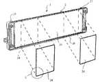
第1の実施形態の小物ホルダー1は、壁面などの被取付面Fに取り付けられるベースプレート2と、このベースプレート2に取り付けられた保持部3とを備えている。ベースプレート2は、長方形板状の基体20と、この基体20の両側に突設された側部21,21とを備えている。さらに、ベースプレート2は、被取付面に取り付けられる取付手段24を基体20の裏面に備えている。保持部3は、複数種類の小物Sに応じて複数種類形成され、この複数種類から選択可能とされている。  Theaccessory holder 1 according to the first embodiment includes abase plate 2 attached to an attachment surface F such as a wall surface, and aholding portion 3 attached to thebase plate 2. Thebase plate 2 includes a rectangular plate-shaped base body 20 andside portions 21 and 21 projecting from both sides of thebase body 20. Further, thebase plate 2 is provided with attachment means 24 attached to the attachment surface on the back surface of thebase body 20. Theholding unit 3 is formed in a plurality of types according to a plurality of types of small articles S, and can be selected from the plurality of types.

基体20は、ABS樹脂などの合成樹脂素材を用いて、射出成形法等により正面視長方形状に成形されている。基体20の裏面側の周囲には、枠部26が突出している。  Thebase body 20 is formed into a rectangular shape in front view by an injection molding method or the like using a synthetic resin material such as ABS resin. Aframe portion 26 protrudes around the back side of thebase body 20.

両側部21,21は、保持部3を支持する部分で、所定の間隔L1を有して基体20前面の両側にビスなどで固定されている。この両側部21,21は、基体20の上端部と下端部が中間部よりも少し飛び出るようにカーブした形態とされ、内壁21a、外壁21b、上壁21c、下壁21dそして前壁21eを有し、ABSなどの合成樹脂により成形されている。  Bothside portions 21 and 21 are portions that support theholding portion 3 and are fixed to both sides of the front surface of thebase 20 with screws or the like with a predetermined interval L1. The bothside portions 21 and 21 are curved so that the upper end portion and the lower end portion of thebase 20 protrude slightly from the middle portion, and have aninner wall 21a, anouter wall 21b, anupper wall 21c, alower wall 21d, and afront wall 21e. However, it is formed of a synthetic resin such as ABS.

両側部21,21の内壁21a,21aの少なくとも一方の端部(図面では下端部)内側面には、図5に示すように、円形に開口した被取付部21gが形成されている。  As shown in FIG. 5, amounting portion 21g having a circular opening is formed on the inner side surface of at least one end (the lower end in the drawing) of theinner walls 21a, 21a of theside portions 21, 21.

取付手段24は、被取付面Fが鉄などの強磁性体を表面側に備えられている場合において、図2および図3に示すように、磁気吸着されるマグネットシート複合材から構成されている。マグネットシート複合材24は、被取付面F(図4,5参照)に向き合う裏面側から順に、滑り止め剤を塗布したマグネットシート24aと、金属製シートとしてのステンレススチール箔のような強磁性体シート24bと、弾力性を有するクッションシート24cとを貼り合わせた構成とされている。  As shown in FIGS. 2 and 3, the attachment means 24 is composed of a magnet sheet composite material that is magnetically attracted when the attachment surface F is provided with a ferromagnetic material such as iron on the surface side. . Themagnet sheet composite 24 includes amagnet sheet 24a coated with a non-slip agent and a ferromagnetic material such as a stainless steel foil as a metal sheet in order from the back side facing the mounting surface F (see FIGS. 4 and 5). The seat 24b and theelastic cushion sheet 24c are bonded together.

マグネットシート24aは、裏面が基体20の枠部26内に奥まらないように埋め込まれている。クッションシート24cは、両面テープや接着剤などによって基体20の裏面に貼着される。図面では、2個の長方形状の取付手段24が基体20に貼着されている。しかし、取付手段24の大きさや形状は、限定されるものではなく、単体であっても3枚以上であってもよい。いずれにしても、マグネットシート24aは、強磁性体を表面側に有する壁面等の被取付面Fに磁気吸着により固定される。  Themagnet sheet 24 a is embedded so that the back surface does not go into theframe portion 26 of thebase body 20. Thecushion sheet 24c is attached to the back surface of thesubstrate 20 with a double-sided tape, an adhesive, or the like. In the drawing, two rectangular attachment means 24 are attached to thebase 20. However, the size and shape of the attachment means 24 are not limited, and may be a single unit or three or more. In any case, themagnet sheet 24a is fixed by magnetic attraction to a mounting surface F such as a wall surface having a ferromagnetic material on the surface side.

取付手段24がクッションシート24cを備えることで、マグネットシート24aが磁気吸着によって被取付面Fに強く当たった際の衝撃を吸収する。さらに、マグネットシート24aが粘着力を有するなど滑り止め加工されていることにより、滑り落ちにくいようにすることができる。そして、マグネットシート24aとクッションシート24cとの間に挟まれた強磁性体シート24bにより、マグネットシート24aの磁気吸着力が強化されている。なお、使用状況に応じて、クッションシート24cや強磁性体シート24bは、必ずしも備えなくてもよい。  Since the attachment means 24 includes thecushion sheet 24c, the impact when themagnet sheet 24a strongly hits the attachment surface F by magnetic attraction is absorbed. Furthermore, since themagnetic sheet 24a is anti-slip processed such as having an adhesive force, it can be prevented from slipping off. The magnetic attractive force of themagnet sheet 24a is enhanced by the ferromagnetic sheet 24b sandwiched between themagnet sheet 24a and thecushion sheet 24c. Note that thecushion sheet 24c and the ferromagnetic sheet 24b do not necessarily have to be provided depending on the use situation.

図1ないし図6に示す小物ホルダー1の保持部3は、トレー30である。トレー30は、底壁30aと左右壁30b,30bと前後壁30c,30dを有し、ABS樹脂などの合成樹脂素材を用いて、射出成形法により平面視長方形状に成形されている。  Theholder 3 of theaccessory holder 1 shown in FIGS. 1 to 6 is atray 30. Thetray 30 has abottom wall 30a, left andright walls 30b and 30b, and front andrear walls 30c and 30d, and is formed into a rectangular shape in plan view by an injection molding method using a synthetic resin material such as ABS resin.

トレー30の横方向(基体20の左右方向)の長さ寸法L2は、トレー30が両側部21,21間に収まるように、基体20の両側部21,21の間隔L1と同等かわずかに短く設定されている。トレー30の基部には、左右に突出する軸部(取付部)30e,30eがそれぞれ設けられており、各軸部30e,30eは両側部21、21の被取付部21gに嵌合することにより取り付けられている。  The length L2 of thetray 30 in the lateral direction (the left-right direction of the base body 20) is equal to or slightly shorter than the distance L1 between theside portions 21 and 21 of thebase body 20 so that thetray 30 fits between the bothside parts 21 and 21. Is set. The base portion of thetray 30 is provided with shaft portions (mounting portions) 30e and 30e protruding left and right. Theshaft portions 30e and 30e are fitted to the mountedportions 21g of theside portions 21 and 21, respectively. It is attached.

これにより、トレー30は、各軸部30eを中心にして回動し、基体20から水平方向に突出する使用姿勢Aと、基体20に沿うような上向きの収納姿勢Bとに姿勢変更自在とされている。  As a result, thetray 30 rotates about eachshaft portion 30e, and can be freely changed in posture between a use posture A that protrudes horizontally from thebase 20 and an upward storage posture B that follows thebase 20. ing.

そして、図4に示すように、基体20前面の下部には、凸条のストッパー部20aが設けられている。トレー30の基部に設けられた後壁30dの上面がストッパー部20aに下方から係止することにより、トレー30は、使用姿勢Aを維持することが可能となる。  As shown in FIG. 4, aconvex stopper 20a is provided at the lower part of the front surface of thebase 20. Since the upper surface of therear wall 30d provided at the base portion of thetray 30 is locked to thestopper portion 20a from below, thetray 30 can maintain the use posture A.

ここで、第1の実施形態の小物ホルダー1を使用する方法について説明する。ここでは、トレー30が収納姿勢Bとされた状態で操作を開始する。  Here, a method of using theaccessory holder 1 of the first embodiment will be described. Here, the operation is started in a state where thetray 30 is in the storage posture B.

先ず、ベースプレート2に貼着された取付手段24のマグネットシート24aを被取付面Fの所定位置に磁気吸着により固定させる。このとき、取付手段24は、マグネットシート24aとクッションシート24cを備えているので、小物ホルダー1を勢いよく被取付面Fに磁気吸着した場合であっても、そのときの衝撃がクッションシート24cによって和らげられるため、衝撃が殆どないソフトな感覚で取り付けることができる。  First, themagnet sheet 24a of the attaching means 24 attached to thebase plate 2 is fixed to a predetermined position on the attachment surface F by magnetic adsorption. At this time, since the attachment means 24 includes themagnet sheet 24a and thecushion sheet 24c, even when theaccessory holder 1 is magnetically attracted to the attachment surface F, the impact at that time is caused by thecushion sheet 24c. Because it is softened, it can be attached with a soft feel with little impact.

そして、トレー30の上部を手前に引くとトレー30は水平状態の使用姿勢Aとなる。このトレー30上には、図6に示すように、調味料などを収納した複数の小物S,Sが適宜載せられる。  When the upper portion of thetray 30 is pulled forward, thetray 30 is in a horizontal use posture A. On thetray 30, as shown in FIG. 6, a plurality of small articles S and S containing seasonings and the like are appropriately placed.

本実施形態の小物ホルダー1は、取付手段24がマグネットシート24aとクッションシート24cとの間に強磁性体シート24bを挟んだ構成として磁気吸着力を上げているので、トレー30上に載せられる小物Sの耐加重値を上げることができる。しかも、マグネットシート24aに滑り止め剤が塗布されることによっても、小物Sの耐荷重値を上げることができる。  In theaccessory holder 1 of the present embodiment, the attachment means 24 increases the magnetic attractive force as a configuration in which the ferromagnetic sheet 24b is sandwiched between themagnet sheet 24a and thecushion sheet 24c. The load resistance value of S can be increased. Moreover, the load resistance value of the accessory S can also be increased by applying an anti-slip agent to themagnet sheet 24a.

そして、小物ホルダー1は、収納姿勢Bにおいて、トレー30が基体20に沿うことで厚さ寸法を抑えることができ、使用しない際だけでなく、店頭における陳列時や輸送時などにおいてコンパクト化を図ることができる。したがって、この小物ホルダーは、輸送コスト、陸上輸送でのCO2(注:「2」は出願時に下添え字にします)、倉庫代などを削減することができる。  In the storage posture B, theaccessory holder 1 can suppress the thickness dimension by thetray 30 being along thebase body 20 and can be made compact not only when not in use but also when being displayed or transported at a store. be able to. Therefore, this accessory holder can reduce transportation costs, CO2 for land transportation (Note: “2” is a subscript at the time of application), warehouse charges, etc.

次に、小物ホルダー1の保持部3としてフック部材31を採用した例について図7を参照しながら説明する。なお、ベースプレート2は、保持部3としてトレー30を使用する場合と同一構造の部品を採用する。  Next, the example which employ | adopted thehook member 31 as the holding |maintenance part 3 of theaccessory holder 1 is demonstrated, referring FIG. Thebase plate 2 employs parts having the same structure as when thetray 30 is used as the holdingunit 3.

フック部材31は両端(片方のみ図示)に軸部31aを有する板状の基板31bと、この基板31bから所定の間隔で前方に突出する複数のフック部31cとを備えている。基板31bの長さ寸法は、前記トレー30の長さ寸法L2と同等、基体20の両側部21,21の間隔L1と同等かわずかに短く設定されている。各軸部31aは、両側部21、21の被取付部21gに嵌合されている。これにより、フック部材31は、各軸部31aを中心にして回動する。すなわち、フック部材31は、使用姿勢Aと、収納姿勢Bとに姿勢変更自在に構成されている。  Thehook member 31 includes a plate-like substrate 31b havingshaft portions 31a at both ends (only one is shown), and a plurality ofhook portions 31c protruding forward from thesubstrate 31b at a predetermined interval. The length of thesubstrate 31b is set to be equal to or slightly shorter than the length L2 of thetray 30 and equal to or slightly shorter than the distance L1 between theside portions 21 and 21 of thebase body 20. Eachshaft portion 31 a is fitted to the attachedportion 21 g of the bothside portions 21, 21. As a result, thehook member 31 rotates about eachshaft portion 31a. That is, thehook member 31 is configured to be freely changeable in a use posture A and a storage posture B.

このようなフック部材31は、図7(b)に示すように、使用姿勢Aにおいてキッチンで使用する柄付きの小物Sをフック部31cに吊り下げておくことができる。小物Sをフック部31cに吊り下げないときは、フック部31cを基体20に沿わせた収納姿勢Bとすることで、コンパクト化される。  As shown in FIG. 7B, such ahook member 31 can suspend a small accessory S with a handle used in the kitchen in the use posture A to thehook portion 31c. When the accessory S is not suspended from thehook portion 31 c, thehook portion 31 c is placed in the storage posture B along thebase body 20, thereby reducing the size.

次に、小物ホルダー1の保持部3としてキッチンペーパーホルダー部材32を採用した例について図8を参照しながら説明する。なお、ベースプレート2は、保持部3としてトレー30を使用する場合と同一構造の部品を採用する。  Next, the example which employ | adopted the kitchenpaper holder member 32 as the holding |maintenance part 3 of theaccessory holder 1 is demonstrated, referring FIG. Thebase plate 2 employs parts having the same structure as when thetray 30 is used as the holdingunit 3.

キッチンペーパーホルダー部材32は、トレー30やフック部材31を取り付けた場合の基体20を天地反転し、被取付部21gが上側に位置するようにして取り付けられる。キッチンペーパーホルダー部材32は、長尺状の基部32aと、基部32aの一端から突出したアーム32bと、基部32aと平行になるようにアーム32bの先端に固定された支持部32cと、引掛けアーム32eとを備えている。  The kitchenpaper holder member 32 is attached so that the base 20 when thetray 30 or thehook member 31 is attached is turned upside down, and the attachedportion 21g is positioned on the upper side. The kitchenpaper holder member 32 includes along base portion 32a, anarm 32b protruding from one end of thebase portion 32a, asupport portion 32c fixed to the tip of thearm 32b so as to be parallel to thebase portion 32a, and a hook arm. 32e.

基部32aおよび支持部32cの長さ寸法は、前記トレー30の長さ寸法L2と同等に設定されている。アーム32bおよび引掛けアーム32eの長さ寸法は、側部21よりも短く設定されている。  The length dimensions of thebase portion 32a and thesupport portion 32c are set to be equal to the length dimension L2 of thetray 30. The length dimensions of thearm 32 b and thehook arm 32 e are set to be shorter than theside portion 21.

基部32aの両端部には、前記被取付部21gに係合して軸支される軸部32dが設けられている。引掛けアーム32eは、基端部を回転軸として揺動し、先端に支持部32cの先端部を引っ掛ける部分(採番せず)を有している。引掛けアーム32eの基端部は、基部32aのアーム32bを有していない端部側の軸部32dに軸支されている。  At both ends of thebase portion 32a,shaft portions 32d that are engaged with and supported by the attachedportion 21g are provided. Thehook arm 32e has a portion (not numbered) that swings around the base end portion as a rotation shaft and hooks the tip end portion of thesupport portion 32c at the tip end. The base end portion of thehook arm 32e is pivotally supported by ashaft portion 32d on the end portion side that does not have thearm 32b of thebase portion 32a.

このようなキッチンペーパーホルダー部材32は、収納姿勢B状態において、図8(a)に示すように、アーム32b、支持部32cおよび引掛けアーム32eが基体20に沿った下向き状態となっている。そして、キッチンペーパーホルダー部材32を使用姿勢Aとするには、図8(b)に示すように、アーム32bを、軸部32dを中心にして上方に回動させアーム32bおよび支持部32cを基体20から離した状態とする。  In such a storage posture B state, the kitchenpaper holder member 32 has thearm 32b, thesupport portion 32c, and thehook arm 32e in a downward state along thebase body 20, as shown in FIG. Then, in order to set the kitchenpaper holder member 32 to the use posture A, as shown in FIG. 8 (b), thearm 32b is pivoted upward about theshaft portion 32d, so that thearm 32b and thesupport portion 32c are the base. The state is separated from 20.

この使用姿勢Aにおいて、図8(b)の仮想線に示すように、支持部32bにロール状に巻き取られたキッチンペーパー(小物)Sの中空芯を挿通する。そして、引掛けアーム32eの引っ掛ける部分を支持部32cの先端部に引っ掛ける。また、キッチンペーパー(小物)Sの外周面が基体20に接触することで、キッチンペーパーホルダー部材20は、使用姿勢Aを維持する。したがって、キッチンペーパーホルダー部材20が使用されるにつれて、アーム32bおよび支持部32cは、基体20に近づいていく。  In this use posture A, as indicated by the phantom line in FIG. 8B, the hollow core of the kitchen paper (small article) S wound in a roll shape is inserted through thesupport portion 32b. Then, the hooking portion of thehook arm 32e is hooked on the tip of thesupport portion 32c. Moreover, the kitchenpaper holder member 20 maintains the use posture A because the outer peripheral surface of the kitchen paper (small article) S contacts thebase body 20. Therefore, as the kitchenpaper holder member 20 is used, thearm 32 b and thesupport portion 32 c approach thebase body 20.

次に、小物ホルダー1の保持部3としてタオル掛け部材33を採用した例について図9に示す。なお、ベースプレート2は、保持部3としてトレー30を使用する場合と同一構造の部品を採用する。  Next, an example in which atowel hanging member 33 is employed as the holdingportion 3 of theaccessory holder 1 is shown in FIG. Thebase plate 2 employs parts having the same structure as when thetray 30 is used as the holdingunit 3.

タオル掛け部材33は、左右一対のアーム33b,33bを有する略U字状のフレーム33aと、各アーム33bの中途部に架け渡される連結部33cとを備えている。フレーム33aの各アーム33bの基端部には、左右に突出する軸部33dがそれぞれ設けられており、各軸部33dは被取付部21g(図5参照)にそれぞれ嵌合されている。  Thetowel hanging member 33 includes a substantiallyU-shaped frame 33a having a pair of left andright arms 33b and 33b, and a connectingportion 33c that spans the middle portion of eacharm 33b.Shaft portions 33d protruding left and right are respectively provided at the base end portions of therespective arms 33b of theframe 33a, and therespective shaft portions 33d are respectively fitted to the attachedportions 21g (see FIG. 5).

これにより、タオル掛け部材33は、各軸部33dを中心にして、図9(b)に示すように基体20から水平方向に突出する使用姿勢Aと、図9(a)に示すように基体20に沿うような上向きの収納姿勢Bとに姿勢変更自在に構成されている。使用姿勢Aの小物置き部材33上には、小物S(図示せず)が置かれたり、フレーム33aや連結部33cに布巾(小物)S(図示せず)が掛けられたりする。タオル掛け部材33が収納姿勢Bとされることで、コンパクトに収納することができる。  As a result, thetowel hanging member 33 is centered on eachshaft portion 33d, as shown in FIG. 9 (b), and the use posture A protruding in the horizontal direction from thebase 20 and the base as shown in FIG. 9 (a). It is configured to be freely changeable in the upward storage posture B along thedirection 20. An accessory S (not shown) is placed on theaccessory holder 33 in the use posture A, or a cloth (small article) S (not shown) is hung on theframe 33a or the connectingportion 33c. When thetowel hanging member 33 is set to the storage posture B, thetowel hanging member 33 can be stored in a compact manner.

以上のように、第1の実施形態は、同一構造のベースプレート2に対して、保持部3としてトレー30、フック部材31、ホルダー部材32および載置部材33のいずれかを選択して取り付けて製造することが可能である。このため、任意の保持部3において同一構造のベースプレート2を兼用することが可能となり、保持部3の種類に応じて専用のベースプレート2を製造する場合に比し、商品コストの削減を図ることができる。  As described above, the first embodiment is manufactured by selecting and attaching any one of thetray 30, thehook member 31, theholder member 32, and the mountingmember 33 as the holdingportion 3 to thebase plate 2 having the same structure. Is possible. For this reason, it becomes possible to share thebase plate 2 having the same structure in any holdingpart 3, and the product cost can be reduced as compared with the case where thededicated base plate 2 is manufactured according to the type of the holdingpart 3. it can.

また、第1の実施形態の周用具1をキッチンなどで使用する際には、同一構造のベースプレート2を使用しているため、使用者が所望する複数種類の保持部3を使用しても、デザインやサイズが統一されるため、洗練されたコーディネートを演出することができる。このように、共通のベースプレート2を採用することで、複数種類の商品として展開した際に、シリーズ性のある商品でることが容易に認知することができ、商品価値を向上することができる。さらに、構成部品を統一することで、パッケージの共有も含めて製造コストを削減することができる。  Moreover, when using theperipheral tool 1 of 1st Embodiment in a kitchen etc., since thebase plate 2 of the same structure is used, even if it uses several types of holding |maintenance parts 3 which a user desires, Since the design and size are unified, sophisticated coordination can be produced. Thus, by adopting thecommon base plate 2, it is possible to easily recognize that the product is a series product when it is developed as a plurality of types of products, and the product value can be improved. Furthermore, by unifying the component parts, it is possible to reduce manufacturing costs including sharing of packages.

〔第2の実施形態〕
本発明に係る小物ホルダー1の第2の実施形態について図10から図20を参照して説明する。なお、第1の実施形態に係る小物ホルダー1と同一部材は、同一符号を付して説明する。
[Second Embodiment]
A second embodiment of theaccessory holder 1 according to the present invention will be described with reference to FIGS. 10 to 20. The same members as those of theaccessory holder 1 according to the first embodiment will be described with the same reference numerals.

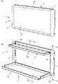
第2の実施形態の小物ホルダー1は、第1の実施形態と同様、ベースプレート2と、保持部3とを備えて構成されている。ただし、第2の実施形態の小物ホルダー1の保持部3は、図10から図14に示すように、上部と下部の2段のトレー30A,30を備えている。  Similar to the first embodiment, theaccessory holder 1 of the second embodiment includes abase plate 2 and a holdingportion 3. However, theholder 3 of theaccessory holder 1 of the second embodiment includes upper and lower two-stage trays 30A and 30 as shown in FIGS.

そのため、第2の実施形態のベースプレート2は、第1の実施形態のベースプレート2よりも高さ方向において長くされている。また、ベースプレート2の両側部21の上部内側面には、図13に示すような上部の被取付部21hが形成されている。上部の被取付部21hは、円形に開口した軸穴部21iと長孔の係止部21jとを連続させた鉤穴形状とされている。  Therefore, thebase plate 2 of the second embodiment is made longer in the height direction than thebase plate 2 of the first embodiment. Further, an upper attachedportion 21 h as shown in FIG. 13 is formed on the upper inner side surface of the bothside portions 21 of thebase plate 2. The upper portion to be attached 21h has a hole shape in which a shaft hole portion 21i that is opened in a circular shape and a lockingportion 21j that is a long hole are continuous.

上部のトレー30Aは、下部のトレー30よりも短く突出した姿勢になるように、使用姿勢Aでの奥行方向が短くされている。上部のトレー30Aは、基体20から水平方向に突出する使用姿勢Aと、下向きになって基体20に沿う収納姿勢Bとに姿勢変更自在とするため、左右に突出する軸部(取付部)30f,30fを基端部に備えている。この軸部30f,30fは、平行な一対の長辺部を有する長円形に形成されている。軸部30f,30fの一対の長辺部の間隔は、上部の被取付部21hの長孔の係止部21jの幅と同じとされている。  The depth direction in the use posture A is shortened so that theupper tray 30A protrudes shorter than thelower tray 30. Theupper tray 30A has a shaft portion (mounting portion) 30f that protrudes left and right so that the posture can be freely changed between a use posture A that protrudes horizontally from thebase body 20 and a storage posture B that faces downward along thebase body 20. , 30f at the base end. Theshaft portions 30f and 30f are formed in an oval shape having a pair of parallel long side portions. The distance between the pair of long side portions of theshaft portions 30f, 30f is the same as the width of the lockingportion 21j of the long hole of the upper attachedportion 21h.

下部のトレー30は、第1の実施形態のトレー30と同様に軸部30eが両側部21、21の下部に設けられた被取付部21gに回動可能に嵌合されている。これにより、下部のトレー30は、軸部30eを中心にして、基体20から水平方向に突出する使用姿勢Aと、上向きの収納姿勢Bとに姿勢変更自在に回動自在とされている。  In thelower tray 30, like thetray 30 of the first embodiment, theshaft portion 30 e is rotatably fitted to the attachedportions 21 g provided at the lower portions of theside portions 21 and 21. As a result, thelower tray 30 is rotatable so that the posture can be freely changed between a use posture A protruding in the horizontal direction from thebase body 20 and an upward storage posture B around theshaft portion 30e.

そして、収納姿勢Bでは、図10(a)に示すように、上向きとなった下部のトレー30が下向きとなった上部のトレー30Aを覆う状態とされる。したがって、この小物ホルダー1は、2枚のトレー30A,30を備えていてもコンパクトに収納することができる。  Then, in the storage posture B, as shown in FIG. 10A, thelower tray 30 that faces upward covers theupper tray 30A that faces downward. Therefore, theaccessory holder 1 can be accommodated in a compact manner even if it has twotrays 30A, 30.

そして、使用姿勢Aでは、図10(b)から図12に示すように、下部のトレー30と上部のトレー30Aが基体20から突出した姿勢とされ、図14に示すようにそれぞれのトレー30,30Aの大きさに適した小物Sが載せられる。  In the use posture A, as shown in FIGS. 10B to 12, thelower tray 30 and theupper tray 30A protrude from thebase 20, and eachtray 30, as shown in FIG. An accessory S suitable for a size of 30A is placed.

上部のトレー30Aは、収納姿勢Bにおいて図13(a)に示すように、軸部30fが上部の被取付部20hの軸穴部21i内で横向きになっているが、水平姿勢とされると、図13(b)に示すように、軸部30fが上部の被取付部20h内で縦向きとなり、使用姿勢Aとされると、図13(c)に示すように、軸部30fが下降して係止部21j内に嵌り込む。  As shown in FIG. 13 (a), theupper tray 30A has ashaft portion 30f in a horizontal position in the shaft hole portion 21i of the upper mounted portion 20h in the storage posture B. As shown in FIG. 13 (b), when theshaft portion 30f is oriented vertically in the upper mounted portion 20h and is in the use posture A, theshaft portion 30f is lowered as shown in FIG. 13 (c). And fitted into the lockingportion 21j.

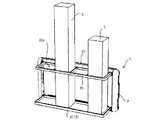
次に、小物ホルダー1の保持部3としてトレー30と位置決め部材35とを組み合わせた小物立を採用した例について図15および図16を参照しながら説明する。  Next, an example in which an accessory stand in which thetray 30 and the positioningmember 35 are combined is adopted as the holdingportion 3 of theaccessory holder 1 will be described with reference to FIGS. 15 and 16.

この保持部3は、ベースプレート2の下部にトレー30を備え、ベースプレート2の上部に位置決め部材35を備えている。トレー30も位置決め部材35も、水平方向に基体20から突出した使用姿勢Aと上向きに基体20に沿う収納姿勢Bとに姿勢変更自在に回動可能とされている。  The holdingunit 3 includes atray 30 below thebase plate 2 and a positioningmember 35 above thebase plate 2. Both thetray 30 and the positioningmember 35 are rotatable in a posture changeable state between a use posture A protruding from the base 20 in the horizontal direction and a storage posture B along the base 20 upward.

位置決め部材35には、複数の挿通開口35aが枠体によって区画形成されている。このような小物立てとして使用する保持部3は、図16に示すように、縦長の小物Sを位置決め部材35の挿通開口35aに挿通させた状態で、トレー30に載せることができる。  In the positioningmember 35, a plurality ofinsertion openings 35a are defined by a frame. As shown in FIG. 16, the holdingunit 3 used as such a small item stand can be placed on thetray 30 in a state where the vertically long small item S is inserted into the insertion opening 35 a of the positioningmember 35.

収納姿勢Bにおいて、トレー30は上向きとなって基体20に沿い、位置決め部材35は下向きとなって基体20に沿い、トレー30の先端縁と位置決め部材35の先端縁とが向き合うようにされている。したがって、この小物ホルダー1は、トレー30と位置決め部材35とを備えていても、コンパクトに収納することができる。  In the storage posture B, thetray 30 faces upward and along thebase 20, and the positioningmember 35 faces downward and along thebase 20, so that the leading edge of thetray 30 and the leading edge of the positioningmember 35 face each other. . Therefore, even if theaccessory holder 1 includes thetray 30 and the positioningmember 35, theaccessory holder 1 can be stored compactly.

次に、小物ホルダー1の保持部3として上側のトレー30と下側のタオル掛け部材36とを組み合わせた例について図17を参照しながら説明する。  Next, an example in which theupper tray 30 and the lowertowel hanging member 36 are combined as the holdingportion 3 of theaccessory holder 1 will be described with reference to FIG.

タオル掛け部材36は、左右一対のアーム部36aと、アーム部36aの先端部に連結される吊り下部36bとによって略U字状に形成されている。  Thetowel hanging member 36 is formed in a substantially U shape by a pair of left andright arm portions 36a and a suspensionlower portion 36b connected to the distal end portion of thearm portion 36a.

そして、各アーム部36aの基端部には、軸部36cが設けられている。この軸部36cが両側部21の被取付部21gに回動可能に嵌合されている。これにより、タオル掛け部材36は、各軸部33dを中心にして、基体20から水平姿勢に突出する使用姿勢Aと、基体20に沿う収納姿勢Bとに姿勢変更自在に回動する。収納姿勢Bのタオル掛け部材36の先端縁がトレー30の基端部に向き合うように、タオル掛け部材36のアーム部36aの長さが設定されている。  A shaft portion 36c is provided at the base end portion of eacharm portion 36a. The shaft portion 36c is rotatably fitted to the attachedportions 21g of the bothside portions 21. As a result, thetowel hanging member 36 rotates about therespective shaft portions 33d so that the posture can be freely changed between a use posture A protruding in a horizontal posture from thebase body 20 and a storage posture B along thebase body 20. The length of thearm portion 36 a of thetowel hanging member 36 is set so that the distal end edge of thetowel hanging member 36 in the storage posture B faces the proximal end portion of thetray 30.

トレー30は、ベースプレート2の両側部21,21の上下方向の略中間部に設けられている。そのため、両側部21,21の中間部には、被取付部としての中段支持開口21jが形成されている。そして、中段支持開口21jにはトレー30の各軸部30eが嵌合している。  Thetray 30 is provided at a substantially intermediate portion in the vertical direction between theside portions 21 and 21 of thebase plate 2. For this reason, amiddle support opening 21j as a mounted portion is formed at the intermediate portion between theside portions 21 and 21. Eachshaft portion 30e of thetray 30 is fitted in themiddle support opening 21j.

これにより、トレー30は、各軸部30eを中心にして、水平方向に基体20から突出した使用姿勢Aと、上向きに基体20に沿った収納姿勢Bとに姿勢変更自在に回動する。したがって、この小物ホルダー1は、トレー30とタオル掛け部材36とを備えていても、コンパクトに収納することができる。  As a result, thetray 30 rotates about therespective shaft portions 30e so that the posture can be freely changed between a use posture A protruding from the base 20 in the horizontal direction and a storage posture B along the base 20 upward. Therefore, even if theaccessory holder 1 includes thetray 30 and thetowel hanging member 36, theaccessory holder 1 can be stored compactly.

次に、小物ホルダー1の保持部3として上側のトレー30と下側のフック部材37とを組み合わせた例について図18を参照しながら説明する。  Next, an example in which theupper tray 30 and thelower hook member 37 are combined as the holdingportion 3 of theaccessory holder 1 will be described with reference to FIG.

フック部材37は軸部37bを有する基部37aと、基部37aから突出した複数のフック部37cとを備えている。フック部材37は、各軸部33dを中心にして、フック部37cが基部20から水平姿勢に突出する使用姿勢Aと、基部20に沿う収納姿勢Bとに姿勢変更自在に回動する。収納姿勢Bにおいて、上向きとなったフック部37cの先端部とトレー30の基端縁とが向き合うようにされている。  Thehook member 37 includes abase portion 37a having a shaft portion 37b and a plurality ofhook portions 37c protruding from thebase portion 37a. Thehook member 37 pivots about therespective shaft portions 33d so that the posture of thehook member 37c can be changed freely between a use posture A in which thehook portion 37c projects in a horizontal posture from thebase portion 20 and a storage posture B along thebase portion 20. In the storage posture B, the tip end portion of thehook portion 37c that faces upward and the base end edge of thetray 30 face each other.

トレー30は、ベースプレート2の両側部21,21の上下方向の略中間部に設けられている。そのため、両側部21,21の中間部には、被取付部としての中段支持開口21jが形成されている。そして、中段支持開口21jにはトレー30の各軸部30eが嵌合している。  Thetray 30 is provided at a substantially intermediate portion in the vertical direction between theside portions 21 and 21 of thebase plate 2. For this reason, amiddle support opening 21j as a mounted portion is formed at the intermediate portion between theside portions 21 and 21. Eachshaft portion 30e of thetray 30 is fitted in themiddle support opening 21j.

これにより、トレー30は、各軸部30eを中心にして、水平方向に基体20から突出した使用姿勢Aと、上向きに基体20に沿う収納姿勢Bとに姿勢変更自在に回動する。したがって、この小物ホルダー1は、トレー30とタオル掛け部材36とを備えていても、収納姿勢Bにおいてコンパクトに収納することができる。  As a result, thetray 30 pivots about therespective shaft portions 30e so that the posture can be freely changed between a use posture A protruding from thebase body 20 in the horizontal direction and a storage posture B along thebase body 20 upward. Therefore, even if theaccessory holder 1 includes thetray 30 and thetowel hanging member 36, theaccessory holder 1 can be stored compactly in the storage posture B.

次に、小物ホルダー1の保持部3として布巾掛け部材38を採用した例について図19を参照しながら説明する。  Next, an example in which acloth hanging member 38 is employed as the holdingportion 3 of theaccessory holder 1 will be described with reference to FIG.

布巾掛け部材38は、一方の側部21の上部の被取付部21hおよび下部の被取付部21gに嵌合される基部38aと、基部38aから水平方向に回動自在に設けられた複数の掛け部38bとを備えている。  Thecloth hanging member 38 includes abase portion 38a fitted to the upper attachedportion 21h and the lower attachedportion 21g of oneside portion 21, and a plurality of hooks provided so as to be rotatable in the horizontal direction from thebase portion 38a.Part 38b.

各掛け部38bは上下方向に所定間隔を有して配置されており、それぞれが、図19(b)に示すように、基体20から異なる角度(図示しないが同じ角度でもよい。)で突出した使用姿勢Aと、図19(a)に示すように、基体20に沿う収納姿勢Bとに姿勢変更自在に水平に回動自在とされている。この小物ホルダー1は、収納姿勢Bにおいて布巾掛け部材38をコンパクトに収納することができる。  Each hangingportion 38b is arranged at a predetermined interval in the vertical direction, and each protrudes from the base 20 at a different angle (not shown, but may be the same angle) as shown in FIG. 19B. As shown in FIG. 19A, the use posture A and the storage posture B along thebase body 20 are horizontally rotatable so as to be freely changeable in posture. Theaccessory holder 1 can store thecloth hanging member 38 in the storage posture B in a compact manner.

次に、小物ホルダー1の保持部3としてキッチンペーパーホルダー部材32を採用した例について図20を参照しながら説明する。  Next, the example which employ | adopted the kitchenpaper holder member 32 as the holding |maintenance part 3 of theaccessory holder 1 is demonstrated, referring FIG.

キッチンペーパーホルダー部材32は、図8で示した第1の実施形態と同じ基本構成とされ、両側部21,21に軸支される基部32aと、基部32aの一端から突出したアーム32bと、基部32aと平行になるようにアーム32bの先端に固定された支持部32cとを備えている。  The kitchenpaper holder member 32 has the same basic configuration as that of the first embodiment shown in FIG. 8, and includes abase portion 32a pivotally supported on bothside portions 21 and 21, anarm 32b protruding from one end of thebase portion 32a, and a base portion And asupport portion 32c fixed to the tip of thearm 32b so as to be parallel to 32a.

このキッチンペーパーホルダー部材32は、アーム32bが斜め下方に傾斜した使用姿勢Aと基体20に沿う収納姿勢Bとに回動可能とされている。このアーム32bは、アーム32bに対する軸部32dの角度を適宜設定することにより、所望の角度に傾斜させ、キッチンペーパーを掛けることができる。また、この小物ホルダー1は、アーム32bを基体20に沿わせた収納姿勢Aとすることで、コンパクトに収納することができる。  The kitchenpaper holder member 32 can be rotated between a use posture A in which thearm 32 b is inclined obliquely downward and a storage posture B along thebase body 20. Thearm 32b can be inclined to a desired angle by setting an angle of theshaft portion 32d with respect to thearm 32b as appropriate, and kitchen paper can be hung thereon. In addition, theaccessory holder 1 can be stored in a compact manner by setting thearm 32b to the storage posture A along thebase body 20.

以上のように、第2の実施形態においても、同一構造のベースプレート2に対して、保持部3として複数のトレー30、タオル掛け部材36、フック部材31、布巾掛け部材38およびホルダー部材32の何れかを複数個または単数選択して取り付けて製造することが可能である。第2の実施形態に係る小物ホルダー1も、複数種類の保持部3のデザインやサイズが統一性を有し、構成部品が共通化されることで、製造コストを削減することができるだけでなく、パッケージを共有することもできる。さらに、この第2の実施形態に係る小物ホルダー1も、輸送コスト、陸上輸送でのCO2、倉庫代を削減することができる。  As described above, also in the second embodiment, any one of the plurality oftrays 30, thetowel hanging member 36, thehook member 31, thecloth hanging member 38, and theholder member 32 as the holdingportion 3 with respect to thebase plate 2 having the same structure. It is possible to manufacture by attaching a plurality or one of them. Theaccessory holder 1 according to the second embodiment also has a uniform design and size of a plurality of types of holdingportions 3 and can not only reduce the manufacturing cost by sharing the components, You can also share packages. Furthermore, theaccessory holder 1 according to the second embodiment can also reduce transportation costs, CO2 in land transportation, and warehouse charges.

〔その他の実施形態〕
本発明は、第1、第2の実施形態に限定されるものではない。ベースプレート2の大きさや形状は、使用される場所や用途に応じて適宜設計変更可能である。また、保持部3も用途に応じて任意の種類ものが採用可能である。したがって、第1、第2実施形態の小物ホルダーは、キッチンで使用する場合以外の洗面所や風呂場など任意の場所に適した保持部を採用することができる。
[Other Embodiments]
The present invention is not limited to the first and second embodiments. The design and design of the size and shape of thebase plate 2 can be changed as appropriate according to the place and use. Also, any kind of holdingunit 3 can be adopted depending on the application. Therefore, the accessory holder of the first and second embodiments can employ a holding unit suitable for an arbitrary place such as a washroom or a bathroom other than when used in a kitchen.

また、第1、第2の実施形態では、取付手段24として、マグネットシート24aを備えたが、マグネットシート24aに替え、あるいはマグネットシート24aとともに、両面接着シートや接着剤、あるいはビスなどによって被取付面Fに取り付けられるようにしてもよい。  Further, in the first and second embodiments, themagnet sheet 24a is provided as the attachment means 24. However, themagnet sheet 24a is used instead of, or together with themagnet sheet 24a, attached by a double-sided adhesive sheet, an adhesive, or a screw. It may be attached to the surface F.

1 小物ホルダー
2 ベースプレート
3 保持部
20 基体
21 側部
21g 被取付部
21h 被取付部
24 取付手段
24a マグネットシート
24b 強磁性体シート
24c クッションシート
30 トレー
30e 軸部(取付部)
31 フック部材
31a 軸部(取付部)
32 ホルダー部材
32d 軸部(取付部)
33 タオル掛け
35 位置決め部材
36 タオル掛け部材
37 フック部材
38 布巾掛け部材
A 使用姿勢
B 収納姿勢
F 被取付面
S 小物
DESCRIPTION OFSYMBOLS 1Small object holder 2Base plate 3Holding part 20 Base |substrate 21Side part 21g Attachedpart 21h Attachedpart 24 Attached means 24a Magnet sheet 24bFerromagnetic sheet24c Cushion sheet 30Tray 30e Shaft part (attachment part)
31Hook member 31a Shaft part (attachment part)
32Holder member 32d Shaft part (attachment part)
33Towel hook 35 Positioningmember 36Towel hook member 37Hook member 38 Cloth hanging member A Usage posture B Storage posture F Mounted surface S Small item

Claims (3)

Translated fromJapanese
被取付面に取り付けられるベースプレートと、このベースプレートに取り付けられた保持部とを備えた小物ホルダーであって、
前記保持部は、複数種類の小物に応じて複数種類形成されるとともに、この複数種類から選択可能とされ、いずれも、小物を保持する使用姿勢と前記ベースプレート側に沿う収納姿勢とに姿勢変更自在とするための取付部を備え、前記ベースプレートは、選択された保持部の取付部と接続可能な一又は二以上の被取付部を備えていることを特徴とする小物ホルダー。
An accessory holder including a base plate attached to a surface to be attached and a holding part attached to the base plate,
The holding portion is formed in a plurality of types according to a plurality of types of accessories, and can be selected from the plurality of types, both of which can be changed in posture between a use posture for holding the accessories and a storage posture along the base plate side. An accessory holder, wherein the base plate includes one or two or more attached parts connectable to the attachment part of the selected holding part.
前記ベースプレートは、被取付面に取り付けられる取付手段を備え、
前記取付手段は、マグネットシートを備えていることを特徴とする請求項1に記載の小物ホルダー。
The base plate includes attachment means attached to the attachment surface,
The accessory holder according to claim 1, wherein the attachment means includes a magnet sheet.
前記取付手段は、前記マグネットシートに積層された強磁性体シートと、この強磁性体シートに積層されたクッションシートとを備えていることを特徴とする請求項2に記載の小物ホルダー。

3. The accessory holder according to claim 2, wherein the attachment means includes a ferromagnetic sheet laminated on the magnet sheet and a cushion sheet laminated on the ferromagnetic sheet.

JP2016083561A2016-04-192016-04-19 Accessory holderActiveJP6747854B2 (en)

Priority Applications (1)

Application NumberPriority DateFiling DateTitle
JP2016083561AJP6747854B2 (en)2016-04-192016-04-19 Accessory holder

Applications Claiming Priority (1)

Application NumberPriority DateFiling DateTitle
JP2016083561AJP6747854B2 (en)2016-04-192016-04-19 Accessory holder

Publications (2)

Publication NumberPublication Date
JP2017192486Atrue JP2017192486A (en)2017-10-26
JP6747854B2 JP6747854B2 (en)2020-08-26

Family

ID=60156239

Family Applications (1)

Application NumberTitlePriority DateFiling Date
JP2016083561AActiveJP6747854B2 (en)2016-04-192016-04-19 Accessory holder

Country Status (1)

CountryLink
JP (1)JP6747854B2 (en)

Cited By (5)

* Cited by examiner, † Cited by third party
Publication numberPriority datePublication dateAssigneeTitle
EP3531434A1 (en)2018-02-262019-08-28Honeywell International Inc.Magnet holder and magnet holder assembly
JP2021061285A (en)*2019-10-032021-04-15ニチレイマグネット株式会社Magnetic wall mounting article
JP2023039821A (en)*2021-09-092023-03-22株式会社LixilArticle receiver
JP2023049026A (en)*2021-09-282023-04-07ニチレイマグネット株式会社Knocked-down article storage instrument
JP2023049025A (en)*2021-09-282023-04-07ニチレイマグネット株式会社Knockdown rack

Citations (9)

* Cited by examiner, † Cited by third party
Publication numberPriority datePublication dateAssigneeTitle
JPS52126028U (en)*1976-03-221977-09-26
JPS533724U (en)*1976-06-281978-01-13
JPH0537187U (en)*1991-10-301993-05-21積水化学工業株式会社 Storage device for wall mounting
JPH0621483U (en)*1992-08-271994-03-22株式会社ニトムズ Magnetic adsorption tool
JP2003253849A (en)*2002-02-272003-09-10Nichirei Magnet KkWall member with magnet and buffer member
JP2003339513A (en)*2002-05-282003-12-02Biruken KkWall-hung storage fixture
JP2004212433A (en)*2002-12-272004-07-29Nichirei Magnet KkDisplay mechanism and wall surface design mechanism
JP2005218487A (en)*2004-02-032005-08-18Lec Inc Magnetic suspension
JP3200872U (en)*2015-07-282015-11-12ニチレイマグネット株式会社 Magnetic composite sheet

Patent Citations (9)

* Cited by examiner, † Cited by third party
Publication numberPriority datePublication dateAssigneeTitle
JPS52126028U (en)*1976-03-221977-09-26
JPS533724U (en)*1976-06-281978-01-13
JPH0537187U (en)*1991-10-301993-05-21積水化学工業株式会社 Storage device for wall mounting
JPH0621483U (en)*1992-08-271994-03-22株式会社ニトムズ Magnetic adsorption tool
JP2003253849A (en)*2002-02-272003-09-10Nichirei Magnet KkWall member with magnet and buffer member
JP2003339513A (en)*2002-05-282003-12-02Biruken KkWall-hung storage fixture
JP2004212433A (en)*2002-12-272004-07-29Nichirei Magnet KkDisplay mechanism and wall surface design mechanism
JP2005218487A (en)*2004-02-032005-08-18Lec Inc Magnetic suspension
JP3200872U (en)*2015-07-282015-11-12ニチレイマグネット株式会社 Magnetic composite sheet

Cited By (10)

* Cited by examiner, † Cited by third party
Publication numberPriority datePublication dateAssigneeTitle
EP3531434A1 (en)2018-02-262019-08-28Honeywell International Inc.Magnet holder and magnet holder assembly
JP2021061285A (en)*2019-10-032021-04-15ニチレイマグネット株式会社Magnetic wall mounting article
JP7065479B2 (en)2019-10-032022-05-12ニチレイマグネット株式会社 Magnetic wall mount article
JP2023039821A (en)*2021-09-092023-03-22株式会社LixilArticle receiver
JP2023049026A (en)*2021-09-282023-04-07ニチレイマグネット株式会社Knocked-down article storage instrument
JP2023049025A (en)*2021-09-282023-04-07ニチレイマグネット株式会社Knockdown rack
JP7410524B2 (en)2021-09-282024-01-10ニチレイマグネット株式会社 Assembled item storage equipment
JP7457402B2 (en)2021-09-282024-03-28ニチレイマグネット株式会社 Assembled rack
JP2024059950A (en)*2021-09-282024-05-01ニチレイマグネット株式会社Assembly type rack
JP7645520B2 (en)2021-09-282025-03-14ニチレイマグネット株式会社 Assembled Rack

Also Published As

Publication numberPublication date
JP6747854B2 (en)2020-08-26

Similar Documents

PublicationPublication DateTitle
JP2017192486A (en) Accessory holder
US20080169218A1 (en)Packaging
US20090079304A1 (en)Product display support systems and methods
TWM355313U (en)Assembly-type hanging hook apparatus
US3017036A (en)Magnetic support
CN215328922U (en)Clothes nursing equipment
KR200471986Y1 (en)Doll is fassion codi case
US20070131631A1 (en)Decorator storage/display system of PEGS & board
US7464494B2 (en)Magnetic card display apparatus
US20070119804A1 (en)Modular magnetic fixture system
JP7500989B2 (en) Support
JP2021164896A (en)table
TWM589661U (en)Storage cart
JP3215190U (en) Combination design free board furniture.
KR20050057736A (en)Adhesive holding pad having suction cups
JP2004089405A (en)Goods display fixture
JP2020078460A (en)Display device
JP3189029U (en) Goods storage case fixture
KR20170003089A (en)Multipurpose hanger
CN208510892U (en)A kind of Combined bathroom supporter
JP3215079U (en) Frame for clothes using magnet adsorbing decorative board
JP2003219928A (en)Optional member for furniture
JP2016214689A (en) Storage device
JP3089445U (en) Universal holder with magnet
JP2017042274A (en)Mounting rack for wall surface, and storage rack for wall surface

Legal Events

DateCodeTitleDescription
A621Written request for application examination

Free format text:JAPANESE INTERMEDIATE CODE: A621

Effective date:20180115

A977Report on retrieval

Free format text:JAPANESE INTERMEDIATE CODE: A971007

Effective date:20181024

A131Notification of reasons for refusal

Free format text:JAPANESE INTERMEDIATE CODE: A131

Effective date:20181029

A521Request for written amendment filed

Free format text:JAPANESE INTERMEDIATE CODE: A523

Effective date:20181217

A02Decision of refusal

Free format text:JAPANESE INTERMEDIATE CODE: A02

Effective date:20190304

A521Request for written amendment filed

Free format text:JAPANESE INTERMEDIATE CODE: A523

Effective date:20190604

A911Transfer to examiner for re-examination before appeal (zenchi)

Free format text:JAPANESE INTERMEDIATE CODE: A911

Effective date:20190614

A912Re-examination (zenchi) completed and case transferred to appeal board

Free format text:JAPANESE INTERMEDIATE CODE: A912

Effective date:20190809

A521Request for written amendment filed

Free format text:JAPANESE INTERMEDIATE CODE: A523

Effective date:20200519

A61First payment of annual fees (during grant procedure)

Free format text:JAPANESE INTERMEDIATE CODE: A61

Effective date:20200806

R150Certificate of patent or registration of utility model

Ref document number:6747854

Country of ref document:JP

Free format text:JAPANESE INTERMEDIATE CODE: R150

R250Receipt of annual fees

Free format text:JAPANESE INTERMEDIATE CODE: R250

R250Receipt of annual fees

Free format text:JAPANESE INTERMEDIATE CODE: R250

R250Receipt of annual fees

Free format text:JAPANESE INTERMEDIATE CODE: R250


[8]ページ先頭

©2009-2025 Movatter.jp