JP2017188923A - Submarine long-distance transmission system and fiber - Google Patents
Submarine long-distance transmission system and fiberDownload PDFInfo
- Publication number
- JP2017188923A JP2017188923AJP2017102248AJP2017102248AJP2017188923AJP 2017188923 AJP2017188923 AJP 2017188923AJP 2017102248 AJP2017102248 AJP 2017102248AJP 2017102248 AJP2017102248 AJP 2017102248AJP 2017188923 AJP2017188923 AJP 2017188923A
- Authority
- JP
- Japan
- Prior art keywords
- dispersion
- fiber
- refractive index
- transmission
- optical fiber
- Prior art date
- Legal status (The legal status is an assumption and is not a legal conclusion. Google has not performed a legal analysis and makes no representation as to the accuracy of the status listed.)
- Pending
Links
- 239000000835fiberSubstances0.000titleclaimsabstractdescription140
- 230000005540biological transmissionEffects0.000titleclaimsabstractdescription73
- 239000006185dispersionSubstances0.000claimsabstractdescription159
- 239000013307optical fiberSubstances0.000claimsabstractdescription27
- 230000003287optical effectEffects0.000claimsabstractdescription16
- 230000001427coherent effectEffects0.000claimsabstractdescription10
- 238000012545processingMethods0.000claimsabstractdescription10
- 238000001514detection methodMethods0.000claimsabstractdescription9
- 238000005253claddingMethods0.000claimsdescription21
- VYPSYNLAJGMNEJ-UHFFFAOYSA-NSilicium dioxideChemical compoundO=[Si]=OVYPSYNLAJGMNEJ-UHFFFAOYSA-N0.000claimsdescription10
- 239000000126substanceSubstances0.000claimsdescription10
- 229910052731fluorineInorganic materials0.000claimsdescription5
- 239000011737fluorineSubstances0.000claimsdescription5
- 230000010287polarizationEffects0.000claimsdescription4
- 230000007423decreaseEffects0.000claimsdescription3
- 229910052732germaniumInorganic materials0.000claimsdescription3
- GNPVGFCGXDBREM-UHFFFAOYSA-Ngermanium atomChemical group[Ge]GNPVGFCGXDBREM-UHFFFAOYSA-N0.000claimsdescription3
- 125000001153fluoro groupChemical groupF*0.000claims1
- 239000000377silicon dioxideSubstances0.000claims1
- 238000013461designMethods0.000description15
- 239000010453quartzSubstances0.000description8
- 238000009825accumulationMethods0.000description5
- 239000002019doping agentSubstances0.000description5
- PXGOKWXKJXAPGV-UHFFFAOYSA-NFluorineChemical compoundFFPXGOKWXKJXAPGV-UHFFFAOYSA-N0.000description4
- 230000008901benefitEffects0.000description4
- 230000000295complement effectEffects0.000description3
- 238000009826distributionMethods0.000description3
- 238000004519manufacturing processMethods0.000description3
- 239000000463materialSubstances0.000description2
- 230000003321amplificationEffects0.000description1
- 238000005229chemical vapour depositionMethods0.000description1
- 230000002860competitive effectEffects0.000description1
- 239000002131composite materialSubstances0.000description1
- 238000012937correctionMethods0.000description1
- 238000011161developmentMethods0.000description1
- 238000010586diagramMethods0.000description1
- 230000005672electromagnetic fieldEffects0.000description1
- 239000002657fibrous materialSubstances0.000description1
- 238000009434installationMethods0.000description1
- 238000012986modificationMethods0.000description1
- 230000004048modificationEffects0.000description1
- 238000003199nucleic acid amplification methodMethods0.000description1
- 238000005457optimizationMethods0.000description1
- 230000009467reductionEffects0.000description1
- 230000035945sensitivityEffects0.000description1
- 230000003595spectral effectEffects0.000description1
- 238000003892spreadingMethods0.000description1
- 230000007480spreadingEffects0.000description1
Images


Classifications
- G—PHYSICS
- G02—OPTICS
- G02B—OPTICAL ELEMENTS, SYSTEMS OR APPARATUS
- G02B6/00—Light guides; Structural details of arrangements comprising light guides and other optical elements, e.g. couplings
- G02B6/02—Optical fibres with cladding with or without a coating
- G02B6/02214—Optical fibres with cladding with or without a coating tailored to obtain the desired dispersion, e.g. dispersion shifted, dispersion flattened
- G02B6/0228—Characterised by the wavelength dispersion slope properties around 1550 nm
- H—ELECTRICITY
- H04—ELECTRIC COMMUNICATION TECHNIQUE
- H04B—TRANSMISSION
- H04B10/00—Transmission systems employing electromagnetic waves other than radio-waves, e.g. infrared, visible or ultraviolet light, or employing corpuscular radiation, e.g. quantum communication
- H04B10/25—Arrangements specific to fibre transmission
- H04B10/2507—Arrangements specific to fibre transmission for the reduction or elimination of distortion or dispersion
- H04B10/2513—Arrangements specific to fibre transmission for the reduction or elimination of distortion or dispersion due to chromatic dispersion
- H04B10/2525—Arrangements specific to fibre transmission for the reduction or elimination of distortion or dispersion due to chromatic dispersion using dispersion-compensating fibres
- H04B10/25253—Arrangements specific to fibre transmission for the reduction or elimination of distortion or dispersion due to chromatic dispersion using dispersion-compensating fibres with dispersion management, i.e. using a combination of different kind of fibres in the transmission system
- G—PHYSICS
- G02—OPTICS
- G02B—OPTICAL ELEMENTS, SYSTEMS OR APPARATUS
- G02B6/00—Light guides; Structural details of arrangements comprising light guides and other optical elements, e.g. couplings
- G02B6/02—Optical fibres with cladding with or without a coating
- G02B6/036—Optical fibres with cladding with or without a coating core or cladding comprising multiple layers
- G02B6/03616—Optical fibres characterised both by the number of different refractive index layers around the central core segment, i.e. around the innermost high index core layer, and their relative refractive index difference
- G02B6/03661—Optical fibres characterised both by the number of different refractive index layers around the central core segment, i.e. around the innermost high index core layer, and their relative refractive index difference having 4 layers only
- G02B6/03666—Optical fibres characterised both by the number of different refractive index layers around the central core segment, i.e. around the innermost high index core layer, and their relative refractive index difference having 4 layers only arranged - + - +
Landscapes
- Physics & Mathematics (AREA)
- Chemical & Material Sciences (AREA)
- Dispersion Chemistry (AREA)
- Electromagnetism (AREA)
- Engineering & Computer Science (AREA)
- Computer Networks & Wireless Communication (AREA)
- Signal Processing (AREA)
- General Physics & Mathematics (AREA)
- Optics & Photonics (AREA)
- Optical Communication System (AREA)
- Optical Fibers, Optical Fiber Cores, And Optical Fiber Bundles (AREA)
Abstract
Description
Translated fromJapanese 関連出願の相互参照
本出願は、本出願の譲受人が所有する2012年8月18日出願の米国特許仮出願第61/684,742号及び2013年8月16日出願の米国特許出願第13/968,601号の優先権の利益を主張するものであり、同出願は、その全体が参照によって本明細書に組み込まれる。CROSS REFERENCE TO RELATED APPLICATIONS This application is filed in U.S. Provisional Application No. 61 / 684,742 filed on August 18, 2012 and U.S. Patent Application No. 13 filed on August 16, 2013, owned by the assignee of the present application. No./968,601, which claims the benefit of priority, which is incorporated herein by reference in its entirety.
本発明は、改善された光学システムおよびファイバに関し、具体的には、海底の長距離光伝送向けに特に適合された光学システムおよびファイバに関する。 The present invention relates to improved optical systems and fibers, and in particular, to optical systems and fibers that are specifically adapted for submarine long-distance optical transmission.
海底の長距離光伝送スパンに対して、長さを増し、データの伝送速度を向上するように、継続的な要求がある。これらの目標を達成するために、伝送部品の光学的性質は、満足できる低レベルの減衰(すなわち伝送損失)および接続損失を達成する一方で、容認できる低レベルの分散および非線形性を保つように構成しなければならない。 There is a continuing demand for increasing the length and improving the data transmission speed for long-haul optical transmission spans on the sea floor. In order to achieve these goals, the optical properties of the transmission components are such that acceptable low levels of attenuation (ie transmission loss) and splice loss are achieved while maintaining acceptable low levels of dispersion and nonlinearity. Must be configured.
したがって、一般的な海底の長距離伝送スパンは、蓄積される分散の量を伝送スパンにわたって制御するために、一般に、分散補償ファイバ(DCF)の長さと、負分散の非ゼロ分散ファイバ(NZDF)の長さを組み合わせて用いる。従来技術による海底の光ファイバ伝送スパンには、増幅ならびに分散スロープの管理のための他の構成要素が含まれることがある。 Thus, a typical submarine long haul transmission span generally includes a length of dispersion compensating fiber (DCF) and a negative dispersion non-zero dispersion fiber (NZDF) to control the amount of accumulated dispersion across the transmission span. Are used in combination. Prior art submarine optical fiber transmission spans may include other components for amplification and dispersion slope management.
これらの伝送スパンの設計は、複数の矛盾する注意事項に配慮しなければならないので複雑である。例えば、特定の設計では、蓄積される分散および分散スロープの両方を管理する特殊なファイバの使用が必要とされることがある。しかし、このようなファイバは、一般に有効面積が比較的小さく、減衰および接続損失が増加する。それに加えて、このようなファイバは、一般的には設計するのも困難であり、製造するのが高くつく。 The design of these transmission spans is complex because multiple conflicting considerations must be taken into account. For example, certain designs may require the use of specialized fibers that manage both the accumulated dispersion and dispersion slope. However, such fibers generally have a relatively small effective area and increase attenuation and splice loss. In addition, such fibers are generally difficult to design and expensive to manufacture.
光ファイバ産業は競争が激しいので、コストを低減する努力が継続されていることにさらに留意されたい。海底伝送システムの長さは10,000km以上である。したがって、製造および据付けの経費の明らかに控え目な低減さえ、長距離システムの全費用に対して顕著な影響を及ぼすことができる。 It should be further noted that the optical fiber industry is highly competitive and efforts to reduce costs continue. The length of the submarine transmission system is 10,000 km or more. Thus, even a modest reduction in manufacturing and installation costs can have a significant impact on the overall cost of a long distance system.
本発明の一態様は、光ファイバ伝送スパンと、伝送される光信号に対して分散補償するための、スパン出力におけるコヒーレント検出とデジタル信号処理のモジュールとを備える海底の長距離伝送システムを対象とする。光ファイバ伝送スパンは、長さが実質的に等しい正分散の第1のファイバおよび負分散の第2のファイバを備える少なくとも1つの光ファイバ対線を含む。第1のファイバおよび第2のファイバは、10,000kmより長い伝送距離で信号出力を供給するように構成されており、動作帯域幅にわたって蓄積される組み合わせた分散が、コヒーレント検出とデジタル信号処理のモジュールの分散補償能力を超過することはない。 One aspect of the present invention is directed to a submarine long distance transmission system comprising a fiber optic transmission span and a module for coherent detection and digital signal processing at the span output for dispersion compensation for the transmitted optical signal. To do. The optical fiber transmission span includes at least one optical fiber pair comprising a positive dispersion first fiber and a negative dispersion second fiber that are substantially equal in length. The first fiber and the second fiber are configured to provide a signal output over a transmission distance greater than 10,000 km, and the combined dispersion accumulated over the operating bandwidth provides coherent detection and digital signal processing. The dispersion compensation capability of the module is never exceeded.
本発明のさらなる態様は、海底の長距離伝送スパンで使用される光ファイバを対象とする。このファイバには、1550nmの伝送波長で、ファイバが、−16から−25ps/nm・kmの範囲の分散係数および0.04から0.02ps/nm2・kmの範囲の分散スロープを有するように構成されたコアおよび複数のクラッド層が備わっている。A further aspect of the present invention is directed to an optical fiber used in a submarine long-distance transmission span. For this fiber, at a transmission wavelength of 1550 nm, the fiber has a dispersion coefficient in the range of −16 to −25 ps / nm · km and a dispersion slope in the range of 0.04 to 0.02 ps / nm2 · km. A structured core and a plurality of cladding layers are provided.
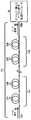
図1は、本発明の一態様による海底の長距離光伝送システム10を示す。システム10は、コヒーレント光の一連のパルスを含む光データ信号12に対して入力端11aと出力端11bの間の伝送経路をもたらす伝送スパン11を備える。スパンの出力端11bは、伝送されるデータ信号12に対する分散補償をもたらすコヒーレント検出およびデジタル信号処理のモジュール14に接続される。 FIG. 1 illustrates a submarine long distance optical transmission system 10 according to one aspect of the present invention. The system 10 comprises a
伝送スパン11は、正分散(D+)を有する第1の伝送ファイバ111の長さおよび負分散(D−)を有する第2の伝送ファイバ112の長さを含む少なくとも1つの光ファイバ対線110を含む。以下で論じられるように、第1のファイバおよび第2のファイバは、伝送されるデータ信号12の分散が、モジュール14の最大の分散補償能力の範囲内になるように構成される。以下でさらに論じられるように、第1のファイバおよび第2のファイバは、光ファイバ対線110が、実質的に長さの等しい第1のファイバと第2のファイバを含むように構成される。最後に、正分散の値D+および負分散の値D−は、ファイバ・スパンの組み合わせが全伝送帯の最小限の残留スパン分散より、大きく、または小さくなるように選択する必要がある。 The
一般に、海底の長距離伝送(LHT)システムには、高帯域および長距離の要求がある。高密度波長分割多重(DWDM)を用いるLHTシステムは、Cバンド(1530nmから1565nm)の範囲内で動作し、1535nmから1565nm(すなわち1550nm±15nm)に及ぶ30nmの帯域幅範囲の信号光波長を利用する。以下で論じられるように、海底のLHTシステムは、現行の用途の要求を満たすために、15,000kmまでの距離を含めて約10,000kmの伝送距離で動作することができるべきである。 In general, submarine long distance transmission (LHT) systems have high bandwidth and long distance requirements. LHT systems using Dense Wavelength Division Multiplexing (DWDM) operate within the C band (1530 nm to 1565 nm) and utilize signal light wavelengths in the 30 nm bandwidth range from 1535 nm to 1565 nm (
分散の問題は、海底のLHTシステムの設計における重要な問題である。分散は、光信号の別々の成分が伝送スパンを通って異速度で進むときにもたらされるデータパルスの一時的な歪み(すなわち「拡散」)と特徴付けることができる。例えば、光信号の成分が別々の波長または偏光の状態を有するとき、速度の差が生じる可能性がある。一般に、正分散ファイバでは、全分散の量は、ファイバの長さの関数として直線的に増大する。したがって、10,000km以上の長さのDWDMファイバ・スパンでは、効果的な分散管理が重要である。 Dispersion issues are an important issue in the design of submarine LHT systems. Dispersion can be characterized as a temporary distortion (or “spreading”) of the data pulse that occurs as different components of the optical signal travel through the transmission span at different rates. For example, when the components of the optical signal have different wavelengths or polarization states, a speed difference can occur. In general, in positive dispersion fibers, the amount of total dispersion increases linearly as a function of fiber length. Therefore, effective dispersion management is important for DWDM fiber spans longer than 10,000 km.
前述のように、システム10では、分散補償をもたらすために、コヒーレント検出およびデジタル信号処理(DSP)のモジュール14が使用される。特に海底のLHTシステムでは、必要な分散補償のうちの少なくともいくらかをデジタル領域で遂行することに関して複数の利点がある。利点の1つには、デジタル信号処理が入来電磁界の完全な情報を維持することがある。したがって、DSPベースのシステムにより、高い受信器感度およびスペクトル効率を達成することができ、先進の変調方式を用いることができる。 As described above, in system 10, a coherent detection and digital signal processing (DSP) module 14 is used to provide dispersion compensation. Particularly in submarine LHT systems, there are several advantages associated with performing at least some of the required dispersion compensation in the digital domain. One advantage is that digital signal processing maintains complete information of the incoming electromagnetic field. Thus, high receiver sensitivity and spectral efficiency can be achieved with DSP-based systems, and advanced modulation schemes can be used.
伝送損失(「減衰」とも称される)および接続損失に関して、DSPを利用する海底LHTシステム向けの最適なファイバの解決策は、大きな有効面積の低損失ファイバになるはずである。しかし、現在入手可能なこのタイプのファイバの分散特性と、現在入手可能なDSP集積回路の分散補償能力とで、伝送スパンの全長が制限される。これらのファイバは、一般に1550nmの伝送波長で、15から22ps/nm・kmの範囲の分散値を有する。海底の伝送向けの現行のファイバ・スパンでは、スパン分散は、低く、すなわち約0から−2ps/nm・kmの範囲の値に保たれる。 With regard to transmission loss (also referred to as “attenuation”) and splice loss, the optimal fiber solution for a submarine LHT system utilizing a DSP should be a large effective area, low loss fiber. However, the dispersion characteristics of currently available fibers of this type and the dispersion compensation capability of currently available DSP integrated circuits limit the total transmission span. These fibers generally have dispersion values in the range of 15 to 22 ps / nm · km at a transmission wavelength of 1550 nm. In current fiber spans for submarine transmission, the span dispersion is kept low, i.e., in the range of about 0 to -2 ps / nm.km.
40GBit/秒および100GBit/秒の伝送向けの現在入手可能なDSP集積回路は、約±30,000ps/nmの数値的分散補償に制限されている。したがって、伝送スパンが15から22ps/nm・kmの範囲の分散値を有すると想定すれば、スパンは約1,500km程度の最大長を有する。現行の海底LHT基準によれば、このスパン長さはかなり短い。前述のように、LHTシステムは、現行の要求を満たすためには、15,000kmの長さを有するスパンを含めて、約10,000km以上のスパン長さでエラーフリーの伝送をもたらすことができるべきである。 Currently available DSP integrated circuits for 40 Gbit / s and 100 Gbit / s transmissions are limited to numerical dispersion compensation of about ± 30,000 ps / nm. Therefore, assuming that the transmission span has a dispersion value in the range of 15 to 22 ps / nm · km, the span has a maximum length of about 1,500 km. According to current submarine LHT standards, this span length is quite short. As mentioned above, LHT systems can provide error-free transmission with span lengths of about 10,000 km or more, including spans with a length of 15,000 km, to meet current requirements. Should.
今後、DSP集積回路が、より大きな全スパンの分散値を扱うことができるようになる可能性がある。しかし、新規のDSP設計の開発は高価で複雑である。それに加えて、このような集積回路は、現在入手可能な製品よりかなり高価であって、かなり大きな電力を消費すると見てよい。したがって、本議論のために、実質的な最大のDSP能力は、当面の間は30,000ps/nm程度にとどまるであろうと想定される。 In the future, DSP integrated circuits may be able to handle larger full span dispersion values. However, the development of new DSP designs is expensive and complex. In addition, it can be seen that such integrated circuits are much more expensive than currently available products and consume significantly more power. Therefore, for the purposes of this discussion, it is assumed that the substantial maximum DSP capability will remain on the order of 30,000 ps / nm for the time being.
分散は、長さによって変化するのに加えて、一般に波長によっても変化する。したがって、対処する必要のある第2の問題は、分散関数のスロープ(すなわち分散と波長間の関係の「しゅん度」)である。所要の動作帯域幅の全体にわたって分散の適切な管理を確実にするために、分散スロープに配慮する必要がある。必要に応じて、分散スロープは、特製の分散補償ファイバ(DCF)によって管理され得る。しかし、これらのファイバは、設計および製造が比較的高くつくことに加えて、有効面積が小さく、伝送損失および接続損失の増加をもたらす。したがって、これらの特製ファイバを使用する必要のないLHTシステムを設計するのが望ましい。 In addition to varying with length, dispersion generally varies with wavelength. Thus, the second problem that needs to be addressed is the slope of the dispersion function (ie, the “shrinkage” of the relationship between dispersion and wavelength). In order to ensure proper management of the distribution over the required operating bandwidth, consideration must be given to the distribution slope. If desired, the dispersion slope can be managed by a custom dispersion compensating fiber (DCF). However, in addition to being relatively expensive to design and manufacture, these fibers have a small effective area, resulting in increased transmission and connection losses. Therefore, it is desirable to design an LHT system that does not require the use of these specialty fibers.
LHTシステム10において、リンクの長さが15,000kmであると想定すると、1キロメートルごとに蓄積される分散の平均は、動作帯域幅の全域で約±2.0ps/nm・kmの範囲に入ることになる。前述のように、海底伝送は、1535nmから1565nm(すなわち1550nm±15nm)の範囲の30nmの帯域幅を用いる。 Assuming that the link length is 15,000 km in the LHT system 10, the average dispersion accumulated per kilometer falls within the range of about ± 2.0 ps / nm · km over the entire operating bandwidth. It will be. As mentioned above, submarine transmission uses a 30 nm bandwidth ranging from 1535 nm to 1565 nm (ie, 1550 nm ± 15 nm).
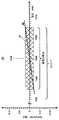
図2は、図1の伝送スパン11に関して、15,000kmのスパン長さを想定した必要な平均分散および分散スロープ特性を説明するグラフ20を示す。図2で、X軸は伝送波長(nm)を表し、Y軸は分散(ps/nm・km)を表す。クロスハッチングされたボックス21は、動作帯域幅の高い方の波長1535nmと低い方の波長1565nmによって左側と右側に境界があり、DSP集積回路で処理可能な分散の範囲、すなわち約±2.0ps/nm・kmによって、その上側と下側に境界がある。 FIG. 2 shows a
したがって、ボックス21は、第1のファイバと第2のファイバを組み合わせた平均の分散の境界を表す。DSP集積回路の最大の分散補償能力を超過しないためには、第1のファイバと第2のファイバを組み合わせた分散関数の平均が、ボックス21の上側と下側の間で、ボックスの左側と右側によって定義された帯域幅に入らなければならない。 Thus,
動作帯域幅にわたる、組み合わせた最大の平均分散スロープは、ボックス21の1つのコーナーから反対側のコーナーに及ぶ破線の対角線22の傾斜で表される。したがって、この実例では、組み合わせた最大の平均分散スロープは、約0.13ps/nm2・km(すなわち分散±2.0ps/nm・kmを帯域幅30nmで割ったもの)である。The combined maximum average dispersion slope over the operating bandwidth is represented by the slope of the dashed diagonal 22 extending from one corner of
したがって、図1に示されたシステム10では、第1のファイバ111および第2のファイバ112のそれぞれの分散特性および長さは、スパン長さを15,000kmと想定して、伝送される信号112が、1535〜1565nmの動作帯域幅を通じて、DSP集積回路の分散補償能力、すなわち約30,000ps/nm・km以内に入る組み合わせた分散を有するように構成される。第1のファイバ111および第2のファイバ112は、比較的大きな有効面積、低減衰、および低接続損失を有するようにさらに構成される。 Accordingly, in the system 10 shown in FIG. 1, the dispersion characteristics and lengths of the
OFS UltraWaveファイバなど、現在入手可能ないくつかの正分散(D+)ファイバは、一見したところでは上記の基準を満たす長距離システムを構成するのに適切であるように思われる。しかし、これらの解決策の最適化は、伝送帯にわたって分散と分散スロープ補償を整合させるという制約を受ける。この制約により、負分散(D−)ファイバの有効面積がかなり制限される。 Some currently available positive dispersion (D +) fibers, such as OFS UltraWave fiber, appear to be suitable for constructing long-range systems that meet the above criteria at first glance. However, optimization of these solutions is constrained by matching dispersion and dispersion slope compensation across the transmission band. This constraint considerably limits the effective area of negative dispersion (D-) fiber.
現在入手可能な対のファイバには、上記の基準を満たすものがない。したがって、本発明の一態様は、所望の組み合わせた分散特性を達成するために、現在入手可能な正分散を有する海底伝送ファイバとともに使用するのに適切な、特別に設計された負分散DCFを提供する。負分散DCFの波長分散係数は、正分散伝送ファイバの波長分散係数に一致し、その結果、実質的に対称なスパン、すなわち正分散ファイバと負分散ファイバの長さが実質的に等しいスパンによって、必要なスパン分散がもたらされ得る。 None of the currently available pairs of fibers meet the above criteria. Thus, one aspect of the present invention provides a specially designed negative dispersion DCF suitable for use with currently available submarine transmission fibers having positive dispersion to achieve the desired combined dispersion characteristics. To do. The chromatic dispersion coefficient of the negative dispersion DCF matches the chromatic dispersion coefficient of the positive dispersion transmission fiber, so that the substantially symmetric span, that is, the span where the lengths of the positive dispersion fiber and the negative dispersion fiber are substantially equal, The required span dispersion can be provided.
スパンが完全に対称でない理由は、2つのファイバのそれぞれの分散関数が、一般に、完全に相補ではないはずであるということである。所望の組み合わせた全分散を達成するには、2つのファイバの相対的長さを調節することが一般に必要となるはずである。本明細書で用いられる用語「実質的に」は、理想的な場合の近似および理想的な場合の両方を含んでいる。したがって、例えば、用語「実質的に等しいスパン」は、構成要素のファイバがほぼ等しい長さを有するスパンと、構成要素のファイバが正確に等しい長さを有するスパンとの両方を指す。 The reason that the span is not perfectly symmetric is that the dispersion function of each of the two fibers should generally not be perfectly complementary. In order to achieve the desired combined total dispersion, it will generally be necessary to adjust the relative lengths of the two fibers. As used herein, the term “substantially” includes both the ideal case approximation and the ideal case. Thus, for example, the term “substantially equal spans” refers to both spans in which the component fibers have approximately equal lengths and spans in which the component fibers have exactly equal lengths.
したがって、正分散ファイバ111と負分散ファイバ112のそれぞれの長さの比は、1:1またはそれに近いものである。この比は、比較的長い正分散係数ファイバ111の使用を可能にするものである。標準的なシングルモード・ファイバ(SSMF)は、正分散の第1のファイバ111として使用するのに適切なファイバの一例である。一般に、SSMFは、少なくとも16ps/nm・kmの正分散係数を有する。 Therefore, the ratio of the lengths of the
伝送ファイバ111およびDCF 112は、分散スロープを管理する必要性なく、適切なDSP構成要素によって、長距離伝送リンクの出力を処理することができるような分散特性を有する。分散スロープを管理する必要がないので、伝送ファイバおよびDCFのそれぞれが、DSP構成要素による伝送リンク出力の処理可能性を損なうことなく、大きな有効面積および低減衰を有するように構成され得る。
本発明の実施の1つでは、正分散の第1のファイバ111は、長距離の海底の用途に適切なシングルモード・ファイバを備え、1550nmの伝送波長で、0.05〜0.07ps/nm2・kmの範囲の分散係数および波長分散スロープを有する。このようなファイバの実例にはUltraWave SLAおよびTeraWave ULAが含まれ、これらは、本出願の譲受人であるOFS Fitel、LLCによって製作、販売されている。In one implementation of the present invention, the positive dispersion
図3は、1550nmの伝送波長における新規のファイバの特性を説明する表30を示す。新規のファイバの波長分散係数は、−16から−25ps/nm・kmの範囲にあって平均値が−20.5ps/nm・kmであり、波長分散スロープは、0.04から0.02ps/nm2・kmの範囲にあって平均値が0.03ps/nm2・kmである。新規のファイバの有効面積は、45から70μm2の範囲にあって平均値が57.5μm2である。新規のファイバの損失は、0.200から0.215dB/kmの範囲にあって平均値が0.2075dB/kmである。FIG. 3 shows a table 30 illustrating the properties of the new fiber at a transmission wavelength of 1550 nm. The new fiber has a chromatic dispersion coefficient in the range of −16 to −25 ps / nm · km, an average value of −20.5 ps / nm · km, and a chromatic dispersion slope of 0.04 to 0.02 ps / km. In the range of nm2 · km, the average value is 0.03 ps / nm2 · km. Effective area of the new fiber has an average value in a range from 45 to 70 [mu] m2 is 57.5μm2. The loss of the new fiber is in the range of 0.200 to 0.215 dB / km with an average value of 0.2075 dB / km.
図4は、第1のファイバ(線41)および第2のファイバ(線42)に関する分散関数およびそれらを組み合わせた平均分散関数(破線43)を示すグラフ40である。本議論のために、3つの分散関数41、42、および43は、それらの平均値に基づいて直線として描かれているが、本議論は、様々な長さのファイバが非直線の(すなわち曲線状の)分散関数を有する伝送システムにも当てはまることが理解されよう。 FIG. 4 is a
グラフ40は、第1のファイバおよび第2のファイバのそれぞれの分散および分散スロープが、伝送帯にわたって非ゼロの残留分散へと結合する様子を示す。グラフ40では、第1のファイバと第2のファイバが正確な相補分散特性を有し、したがって、このスパンは、長さが等しい第1のファイバおよび第2のファイバを備えると想定されている。上記で論じたように、第1のファイバの分散特性と第2のファイバの分散特性が正確に一致しない場合には、所望の組み合わせた全出力分散を達成するために、一般に、第1のファイバと第2のファイバの相対的長さを調節することが必要になる。その場合、組み合わせた分散スロープの平均を計算する際に、使用されている別々の量の2つのファイバを考慮に入れることが必要になる。
グラフ40では、第1のファイバの分散関数は線41で示されており、1550nmで20.5ps/nm・kmの正分散係数を示す。0.06ps/nm2・kmの一定の正分散スロープを想定すると、分散係数は、1535nmにおける19.6ps/nm・kmから1565nmにおける21.4ps/nm・kmの範囲にある。In
第2のファイバの分散関数は線41で示されており、1550nmで−20.5ps/nm・kmの負分散係数を示す。ファイバが0.03ps/nm2・kmの一定の正分散スロープを有すると想定すれば、ファイバの分散係数は、1535nmにおける−20.95ps/nm・kmから1565nmにおける−20.05ps/nm・kmの範囲にある。The dispersion function of the second fiber is shown by
組み合わせた平均分散関数は、破線43で示されており、1550nmでゼロ分散係数を示す。平均分散スロープは0.045ps/nm2・kmである。したがって、組み合わせた平均分散係数は、1535nmにおける−0.0675ps/nm・kmから1565nmにおける0.0675ps/nm・kmの範囲にある。比較のために、グラフ40の中に図2からのボックス21の輪郭を描くのに破線を用いた。組み合わせた平均分散が、申し分なく必要な境界の範囲内にあることが理解されよう。The combined average dispersion function is shown by the dashed
図5は、長さが100kmの第1のファイバおよび第2のファイバを備える15,000kmの伝送スパンの蓄積される分散を示すグラフ50である。説明のために、第1のファイバと第2のファイバは、正確な相補分散特性を有し、ファイバ長と分散の蓄積の間には完全な直線状の関係があると想定されている。 FIG. 5 is a
上向き傾斜の線部分51によって示されるように、第1のファイバが1550nmにおいて20.5ps/nm・kmの正分散係数を有すると想定すると、第1のファイバのそれぞれの100kmの部分が、1550nmで2,050ps/nmの分散の蓄積を招く。下向き傾斜の線部分52によって示されるように、第2のファイバが1550nmにおいて−20.5ps/nm・kmの負分散係数を有すると想定すると、第1のファイバのそれぞれの100kmの部分が、1550nmで2,050ps/nmだけ分散の蓄積を低減する。したがって、それぞれ200kmの第1のファイバと第2のファイバの対は、1550nmにおける分散の蓄積がゼロである。15,000kmの伝送スパンは、このような第1のファイバと第2のファイバの対を75本用いる。 Assuming that the first fiber has a positive dispersion coefficient of 20.5 ps / nm · km at 1550 nm, as indicated by the upwardly
しかし、上記で論じたように、第1のファイバと第2のファイバは、非ゼロの組み合わせた分散スロープを有する。したがって、グラフ50は、15,000kmの伝送距離において、1550nmでは分散の蓄積がゼロであることを示しているが、1535nm〜1565nm帯域幅の中には、分散が蓄積される他の波長が存在することになる。2つのファイバの組み合わせた平均分散スロープが0.045ps/nm2・kmであると想定すると、これは、動作帯域幅の全域で、スパン出力における分散値の予想範囲が約±10,000ps/nmになり、したがって現在入手可能なDSP集積回路によって処理可能であることを意味する。However, as discussed above, the first fiber and the second fiber have non-zero combined dispersion slopes. Therefore,
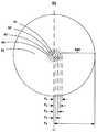
図6は、本発明のさらなる態様による、前述の分散特性を有する例示的DCFの設計60の断面図(原寸に比例したものではない)を示す。ファイバ60は、石英または他の適切な材料から製作され、コア61と、コアを取り囲む複数のクラッド層62〜65とを含む。コアおよびクラッド層は、ファイバ材料に付加される、屈折率を増加させる(index−raising)化学的ドーパントおよび屈折率を減少させる(index−lowering)化学的ドーパントを使用することによって作製される。示されたファイバは,化学的気相堆積法など(MCVD)を用いて製作することができる。 FIG. 6 shows a cross-sectional view (not to scale) of an
図7は、ファイバ60に関する例示的屈折率プロファイル70を示す。屈折率プロファイル70において、X軸はファイバを横切って延在する直径を表し、屈折率値71〜75はファイバ領域61〜65に対応する。屈折率値71〜75は、ファイバ60の長さのずっと先へ延在する複数の導波路をもたらすように構成される。 FIG. 7 shows an exemplary refractive index profile 70 for the
本発明の実施によれば、最も外側のクラッド層65は非ドープの石英から製作される。外側のクラッド65の屈折率n0は、他のファイバ領域のそれぞれの屈折率n1〜n4のそれぞれから減算される基準線の基準値として用いられ、各ファイバ領域に関するそれぞれの屈折率差Δn1〜Δn4をもたらす。In accordance with the practice of the invention, the
図6および図7に示されるように、ファイバ60は以下の領域を含んでいる。
1.ファイバ60の中心にはコア領域61/71があり、半径r1、屈折率n1、および屈折率差Δn1=n1−n0を有する。コア領域61/71は、比較的大きなΔn1をもたらすために、ゲルマニウムまたは屈折率を上昇させる他の適切な化学物質でアップドープされた石英によって与えられ、屈折率プロファイル70における中央のスパイク71をもたらす。
2.環状の「内側トレンチ」領域62/72は、コア領域61/71を取り囲み、内側半径r1、外側半径r2、屈折率n2、および屈折率差Δn2=n2−n0を有する。トレンチ領域62/72は、外側のクラッドn0より低い屈折率n2(すなわちΔn2は負である)をもたらすために、フッ素または他の屈折率を減少させる化学物質でダウンドープされた石英から形成される。
3.環状の「リング」領域63/73は、トレンチ領域62/72を取り囲み、内側半径r2、外側半径r3、屈折率n3、および屈折率差Δn3=n3−n0を有する。トレンチ領域63/73は、外側のクラッドより高い屈折率(すなわちΔn3は正である)をもたらすために、フッ素または他の屈折率を増加させる化学物質でアップドープされた石英から形成される。
4.環状の「外側トレンチ」領域64/74は、リング領域63/73を取り囲み、内側半径r3、外側半径r4、屈折率n4、および屈折率差Δn4=n4−n0を有する。トレンチ領域64/74は、外側のクラッドn0よりわずかに低い屈折率n4(すなわちΔn4は負である)をもたらすために、フッ素または他の屈折率を減少させる化学物質でダウンドープされた石英から形成される。
5.外側のクラッド65/75は、外側のトレンチ領域64/74を取り囲み、内側半径r4、外半径r0、屈折率n0、および屈折率差Δn0=n0−n0=0を有する。As shown in FIGS. 6 and 7, the
1. At the center of the
2. An annular “inner trench”
3. An annular “ring”
4). An annular “outer trench”
5. The
ファイバ60の設計は、本明細書では、一般に「改良型トリプルクラッド設計」と称され、コアが、トレンチ・クラッド層62、リング・クラッド層63、ならびに複合の第3のクラッド640、すなわち浅い外側のトレンチ64および外側のクラッド65で取り囲まれる。このタイプの設計は、「4部からなるクラッド設計」とも称され得る。例えば、完全に非ドープの石英から第3のクラッド640が製作される設計、すなわちファイバが外側のトレンチ64を含んでいない設計を含む、他のタイプの設計を伴う特許請求された発明を実施することができることが理解されよう。 The design of the
前述のように、本実例では、ファイバ60は、屈折率を増加させるドーパントとしてゲルマニウムを用い、屈折率を減少させるドーパントおよびフッ素を用いて石英から形成される。しかし、説明された発明が、他の適切な材料もしくはドーパント、またはそれらの組合せを用いて実施され得ることが理解されよう。さらに、屈折率プロファイル60は、各ファイバ領域が、その幅の全域で同一の屈折率を有する「段の」プロファイルを示すが、実際の実施では、それぞれのファイバ領域の変化が、特に、隣接した領域間の境界に近接して存在することになる。それに加えて、説明された発明は、段階的な屈折率プロファイルを含む設計で実施され得ることがさらに理解されよう。 As described above, in this example,
既に言及されたものに加えて、対象の別の光ファイバ特性には偏光モード分散(PMD)がある。現況技術のケーブルに対する許容限度の範囲内のPMDは、まさに論じられた特性および屈折率プロファイルを有する光ファイバでは一般的である。これらの光ファイバのPMDに関する有効な仕様は、0.04ps/km1/2以下である。In addition to those already mentioned, another optical fiber property of interest is polarization mode dispersion (PMD). PMD, which is within acceptable limits for state-of-the-art cables, is common in optical fibers with the properties and refractive index profile just discussed. An effective specification for PMD of these optical fibers is 0.04 ps / km1/2 or less.
上記で説明されたDCFは、特に、対になった長さの正分散係数のファイバおよび負分散係数のファイバを使用する海底伝送ケーブルの用途向けに設計される。しかし、これらの独特な伝送特性を有する光ファイバに対して、他の用途が見いだされる可能性があることを理解されたい。 The DCF described above is specifically designed for submarine transmission cable applications that use paired lengths of positive dispersion fiber and negative dispersion fiber. However, it should be understood that other applications may be found for optical fibers having these unique transmission characteristics.
結論
前述の説明は、当業者による本発明の実施を可能にすることになる詳細を含んでいるが、この説明は本来例示的であり、これらの教示の利益を有する当業者には、多くの修正形態および変形形態が明らかになるはずであることを理解されたい。したがって、本明細書の発明は、添付の特許請求の範囲によってのみ定義され、特許請求の範囲は、従来技術によって可能な限り広義に解釈されることが意図されている。CONCLUSION While the foregoing description includes details that will enable one of ordinary skill in the art to practice the invention, the description is exemplary in nature and will be appreciated by those skilled in the art having the benefit of these teachings. It should be understood that modifications and variations should be apparent. Accordingly, the invention herein is defined solely by the appended claims, which are intended to be interpreted as broadly as possible by the prior art.
Claims (16)
Translated fromJapanese光信号を伝送し、前記伝送された光信号を出力として供給する光ファイバ伝送スパンと、
前記伝送された光信号に分散補償をもたらすコヒーレント検出とデジタル信号処理のモジュールとを備え、
前記光ファイバ伝送スパンは、正分散の第1のファイバと、長さが実質的に等しい負分散の第2のファイバとを備える少なくとも1つの光ファイバ対線を含み、
前記正分散ファイバの長さおよび前記負分散ファイバの長さは、10,000km以上の伝送距離において前記伝送された光信号の全分散が動作帯域幅の全域で前記コヒーレント検出とデジタル信号処理のモジュールの最大能力の範囲内に入るような、それぞれの分散特性を有するように構成される、システム。A submarine long-distance transmission system,
An optical fiber transmission span for transmitting an optical signal and supplying the transmitted optical signal as an output;
A coherent detection and digital signal processing module that provides dispersion compensation to the transmitted optical signal;
The optical fiber transmission span includes at least one optical fiber pair comprising a positive dispersion first fiber and a negative dispersion second fiber of substantially equal length;
The length of the positive dispersion fiber and the length of the negative dispersion fiber are the coherent detection and digital signal processing modules over the entire operating bandwidth where the total dispersion of the transmitted optical signal is at a transmission distance of 10,000 km or more. The system is configured to have respective dispersion characteristics that fall within the maximum capacity of the system.
コアと、
前記コアを取り囲む複数のクラッド層とを備え、
前記コアおよび前記複数のクラッド層は、前記光ファイバが、1500nmの伝送波長で−16から−25ps/nm・kmの範囲の分散係数を有し、1550nmの伝送波長で0.04から0.02ps/nm2・kmの範囲の分散スロープを有するように構成される、光ファイバ。An optical fiber used in a long-distance transmission span on the sea floor,
The core,
A plurality of cladding layers surrounding the core,
The core and the plurality of cladding layers include: the optical fiber has a dispersion coefficient in the range of −16 to −25 ps / nm · km at a transmission wavelength of 1500 nm, and 0.04 to 0.02 ps at a transmission wavelength of 1550 nm. An optical fiber configured to have a dispersion slope in the range of / nm2 · km.
複数のクラッド層を備え、前記複数のクラッド層が、
内側半径r1と、外側半径r2と、n0より小さい屈折率n2と、負の屈折率差Δn2=n2−n0とを有する、前記コアを取り囲む環状の内側のトレンチ、
内側半径r2と、外側半径r3、n0より大きい屈折率n3と、正の屈折率差Δn3=n3−n0とを有する、前記内側のトレンチを取り囲む環状のリング、及び、
内側半径r3と外側半径r0とを有する、前記リングを取り囲む第3のクラッド領域を備え、前記第3のクラッド領域の少なくとも一部分が、屈折率n0と屈折率差Δn0=n0−n0=0とを有する領域を含む、請求項8に記載の光ファイバ。The core has a radiusr 1, the reference refractive indexn 0 is greater than the refractive indexn 1, and a positive index difference Δn1 =n1 -n0 and,
A plurality of cladding layers, the plurality of cladding layers,
An annular inner trench surrounding the core having an inner radius r1 , an outer radius r2 , a refractive index n2 less than n0, and a negative refractive index difference Δn2 = n2 −n0 ;
An annular ring surrounding the inner trench having an inner radius r2 , an outer radius r3 , a refractive index n3 greater than n0, and a positive refractive index difference Δn3 = n3 −n0 ;
A third cladding region having an inner radius r3 and an outer radius r0 surrounding the ring, wherein at least a portion of the third cladding region has a refractive index n0 and a refractive index difference Δn0 = n0 − The optical fiber of claim 8, comprising a region having n0 = 0.
前記外側のトレンチは前記第3のクラッド領域の内側部分を備え、前記外側のトレンチは、内側半径r3と、外側半径r4と、n0より小さい屈折率n4と、負の屈折率差Δn0=n4−n0とを有する、請求項12に記載の光ファイバ。Further comprising an outer trench surrounding the ring;
The outer trench comprises an inner portion of the third cladding region, the outer trench comprising an inner radius r3 , an outer radius r4 , a refractive index n4 less than n0, and a negative refractive index difference. The optical fiber according to claim 12, wherein Δn0 = n4 −n0 .
Applications Claiming Priority (4)
| Application Number | Priority Date | Filing Date | Title |
|---|---|---|---|
| US201261684742P | 2012-08-18 | 2012-08-18 | |
| US61/684,742 | 2012-08-18 | ||
| US13/968,601 | 2013-08-16 | ||
| US13/968,601US9036998B2 (en) | 2012-08-18 | 2013-08-16 | Long-haul undersea transmission system and fiber |
Related Parent Applications (1)
| Application Number | Title | Priority Date | Filing Date |
|---|---|---|---|
| JP2015159749ADivisionJP2016007038A (en) | 2012-08-18 | 2015-08-13 | Submarine long-distance transmission system and fiber |
Publications (1)
| Publication Number | Publication Date |
|---|---|
| JP2017188923Atrue JP2017188923A (en) | 2017-10-12 |
Family
ID=50100111
Family Applications (3)
| Application Number | Title | Priority Date | Filing Date |
|---|---|---|---|
| JP2013169574APendingJP2014082753A (en) | 2012-08-18 | 2013-08-19 | Submarine long-distance transmission system and fiber |
| JP2015159749APendingJP2016007038A (en) | 2012-08-18 | 2015-08-13 | Submarine long-distance transmission system and fiber |
| JP2017102248APendingJP2017188923A (en) | 2012-08-18 | 2017-05-24 | Submarine long-distance transmission system and fiber |
Family Applications Before (2)
| Application Number | Title | Priority Date | Filing Date |
|---|---|---|---|
| JP2013169574APendingJP2014082753A (en) | 2012-08-18 | 2013-08-19 | Submarine long-distance transmission system and fiber |
| JP2015159749APendingJP2016007038A (en) | 2012-08-18 | 2015-08-13 | Submarine long-distance transmission system and fiber |
Country Status (2)
| Country | Link |
|---|---|
| US (1) | US9036998B2 (en) |
| JP (3) | JP2014082753A (en) |
Families Citing this family (1)
| Publication number | Priority date | Publication date | Assignee | Title |
|---|---|---|---|---|
| US20170336572A1 (en)* | 2016-05-18 | 2017-11-23 | Teledyne Instruments, Inc. | Epoxy-less optical connector termination apparatus for high temperature and high pressure use |
Citations (8)
| Publication number | Priority date | Publication date | Assignee | Title |
|---|---|---|---|---|
| JP2002082251A (en)* | 2000-06-23 | 2002-03-22 | Sumitomo Electric Ind Ltd | Optical fiber, optical transmission line and dispersion compensation module |
| JP2003255170A (en)* | 2001-10-26 | 2003-09-10 | Fujikura Ltd | Dispersion compensating optical fiber and dispersion compensating optical fiber module |
| JP2004086061A (en)* | 2002-08-28 | 2004-03-18 | Sumitomo Electric Ind Ltd | Dispersion compensator and optical communication system |
| JP2006514316A (en)* | 2003-10-03 | 2006-04-27 | ドラカ・コムテツク・ベー・ベー | Chromatic dispersion compensating optical fiber |
| JP2007108764A (en)* | 2006-10-30 | 2007-04-26 | Fujikura Ltd | Optical fiber and optical transmission line using the same |
| US20090324224A1 (en)* | 2008-06-30 | 2009-12-31 | Chongjin Xie | System, method and apparatus to suppress inter-channel nonlinearities in WDM systems with coherent detection |
| US20110064368A1 (en)* | 2009-09-11 | 2011-03-17 | Dana Craig Bookbinder | Low Bend Loss Optical Fiber |
| WO2012082833A1 (en)* | 2010-12-14 | 2012-06-21 | Tyco Electronics Subsea Communications Llc | Dispersion management in optical networks including both coherent and direct detection receivers |
Family Cites Families (5)
| Publication number | Priority date | Publication date | Assignee | Title |
|---|---|---|---|---|
| US6307985B1 (en)* | 1998-07-10 | 2001-10-23 | Micro Therapeutics, Inc. | Optical transmission system |
| US6473550B1 (en)* | 1999-09-27 | 2002-10-29 | Sumitomo Electric Industries, Ltd. | Optical fiber transmission-line |
| AU783168B2 (en)* | 2000-06-23 | 2005-09-29 | Sumitomo Electric Industries, Ltd. | Optical fiber, optical transmission line and dispersion compensating module |
| US8494368B2 (en)* | 2010-04-16 | 2013-07-23 | Alcatel Lucent | Electronic nonlinearity compensation for optical transmission systems |
| US20110318019A1 (en)* | 2010-06-29 | 2011-12-29 | Tyco Electronics Subsea Communication LLC | Communication transmission system with optically aided digital signal processing dispersion compensation |
- 2013
- 2013-08-16USUS13/968,601patent/US9036998B2/enactiveActive
- 2013-08-19JPJP2013169574Apatent/JP2014082753A/enactivePending
- 2015
- 2015-08-13JPJP2015159749Apatent/JP2016007038A/enactivePending
- 2017
- 2017-05-24JPJP2017102248Apatent/JP2017188923A/enactivePending
Patent Citations (8)
| Publication number | Priority date | Publication date | Assignee | Title |
|---|---|---|---|---|
| JP2002082251A (en)* | 2000-06-23 | 2002-03-22 | Sumitomo Electric Ind Ltd | Optical fiber, optical transmission line and dispersion compensation module |
| JP2003255170A (en)* | 2001-10-26 | 2003-09-10 | Fujikura Ltd | Dispersion compensating optical fiber and dispersion compensating optical fiber module |
| JP2004086061A (en)* | 2002-08-28 | 2004-03-18 | Sumitomo Electric Ind Ltd | Dispersion compensator and optical communication system |
| JP2006514316A (en)* | 2003-10-03 | 2006-04-27 | ドラカ・コムテツク・ベー・ベー | Chromatic dispersion compensating optical fiber |
| JP2007108764A (en)* | 2006-10-30 | 2007-04-26 | Fujikura Ltd | Optical fiber and optical transmission line using the same |
| US20090324224A1 (en)* | 2008-06-30 | 2009-12-31 | Chongjin Xie | System, method and apparatus to suppress inter-channel nonlinearities in WDM systems with coherent detection |
| US20110064368A1 (en)* | 2009-09-11 | 2011-03-17 | Dana Craig Bookbinder | Low Bend Loss Optical Fiber |
| WO2012082833A1 (en)* | 2010-12-14 | 2012-06-21 | Tyco Electronics Subsea Communications Llc | Dispersion management in optical networks including both coherent and direct detection receivers |
Also Published As
| Publication number | Publication date |
|---|---|
| JP2014082753A (en) | 2014-05-08 |
| US9036998B2 (en) | 2015-05-19 |
| JP2016007038A (en) | 2016-01-14 |
| US20140050481A1 (en) | 2014-02-20 |
Similar Documents
| Publication | Publication Date | Title |
|---|---|---|
| JP5425391B2 (en) | Optical fiber | |
| US7519255B2 (en) | Optical fiber | |
| JP5242405B2 (en) | Optical fiber and optical fiber transmission line | |
| JP6361101B2 (en) | Optical fiber | |
| US9261646B2 (en) | Optical fiber with large effective area | |
| US7773845B2 (en) | Optical fiber and optical-fiber transmission line | |
| US20160363725A1 (en) | Multimode Optical Fiber with High Bandwidth Over an Extended Wavelength Range, and Corresponding Multimode Optical System | |
| CN103649797A (en) | Step-index few-mode fiber deigns for spatial multiplexing | |
| KR20010088808A (en) | Dispersion compensating fiber | |
| WO2013160714A1 (en) | Hybrid single and multimode optical fiber for a home network | |
| WO2019138848A1 (en) | Optical fiber, coated optical fiber, and optical transmission system | |
| JP2006227173A (en) | Multimode dispersion compensating fiber, mode dispersion compensation method, optical waveguide, optical transmission line, and optical communication system | |
| JP2013201755A (en) | Controlling differential group delay in mode division multiplexed optical fiber systems | |
| US20080219667A1 (en) | Optical communication system and dispersion-compensating optical fiber | |
| JP2017188923A (en) | Submarine long-distance transmission system and fiber | |
| US20120148258A1 (en) | Optical communications system | |
| US20110243519A1 (en) | Optical fibers with truncated cores | |
| JP6258618B2 (en) | Multi-core optical fiber | |
| JP5937974B2 (en) | Multimode optical fiber and optical fiber transmission system | |
| US7565048B1 (en) | Undersea optical fiber transmission systems | |
| US6813426B2 (en) | Fiber with continuously changing chromatic dispersion | |
| EP2362251B1 (en) | Optical fibers with truncated cores | |
| JP4358127B2 (en) | Mode dispersion compensation method and optical waveguide | |
| JP2008268974A (en) | Dispersion compensating fiber module and optical fiber transmission line |
Legal Events
| Date | Code | Title | Description |
|---|---|---|---|
| A131 | Notification of reasons for refusal | Free format text:JAPANESE INTERMEDIATE CODE: A131 Effective date:20180206 | |
| A521 | Request for written amendment filed | Free format text:JAPANESE INTERMEDIATE CODE: A523 Effective date:20180502 | |
| A02 | Decision of refusal | Free format text:JAPANESE INTERMEDIATE CODE: A02 Effective date:20181023 |