JP2017184516A - Power supply device for reefer container, and power supply method for reefer container - Google Patents
Power supply device for reefer container, and power supply method for reefer containerDownload PDFInfo
- Publication number
- JP2017184516A JP2017184516AJP2016070387AJP2016070387AJP2017184516AJP 2017184516 AJP2017184516 AJP 2017184516AJP 2016070387 AJP2016070387 AJP 2016070387AJP 2016070387 AJP2016070387 AJP 2016070387AJP 2017184516 AJP2017184516 AJP 2017184516A
- Authority
- JP
- Japan
- Prior art keywords
- power
- container
- leafer
- power supply
- reefer
- Prior art date
- Legal status (The legal status is an assumption and is not a legal conclusion. Google has not performed a legal analysis and makes no representation as to the accuracy of the status listed.)
- Pending
Links
- 238000000034methodMethods0.000titleclaimsdescription10
- 238000006243chemical reactionMethods0.000claimsdescription13
- 230000005611electricityEffects0.000claimsdescription4
- 239000000446fuelSubstances0.000claimsdescription4
- 239000002028BiomassSubstances0.000claimsdescription3
- 238000009423ventilationMethods0.000abstractdescription8
- 238000010248power generationMethods0.000description8
- VGGSQFUCUMXWEO-UHFFFAOYSA-NEtheneChemical compoundC=CVGGSQFUCUMXWEO-UHFFFAOYSA-N0.000description4
- 239000005977EthyleneSubstances0.000description4
- 238000005260corrosionMethods0.000description4
- 230000007797corrosionEffects0.000description4
- 238000010586diagramMethods0.000description4
- 235000012055fruits and vegetablesNutrition0.000description4
- 239000000126substanceSubstances0.000description4
- 239000000470constituentSubstances0.000description3
- 239000011810insulating materialSubstances0.000description2
- HBBGRARXTFLTSG-UHFFFAOYSA-NLithium ionChemical compound[Li+]HBBGRARXTFLTSG-UHFFFAOYSA-N0.000description1
- 229910001416lithium ionInorganic materials0.000description1
- 230000009466transformationEffects0.000description1
Images


Landscapes
- Charge And Discharge Circuits For Batteries Or The Like (AREA)
- Devices That Are Associated With Refrigeration Equipment (AREA)
- Direct Current Feeding And Distribution (AREA)
Abstract
Description
Translated fromJapanese本発明は、リーファコンテナに用いる電力供給装置、及び、リーファコンテナの電力供給方法に関するものである。 The present invention relates to a power supply device used for a leafer container and a power supply method for the leafer container.
リーファコンテナは温度を一定に保ちながら輸送できるコンテナとして知られている。すなわち、リーファコンテナはコンテナ内を冷凍状態や冷蔵状態にできるのはもちろん、コンテナ内を常温に維持することも可能である。また、温度のみならず、換気機能なども有するため湿度を適正な状態に調整することができ、さらに、エチレンガスを放出し、エチレンガスの量を抑制することもできる。 Leafer containers are known as containers that can be transported while keeping the temperature constant. That is, the reefer container can maintain the inside of the container at room temperature as well as the inside of the container in a frozen state or a refrigerated state. Further, since it has not only temperature but also ventilation function, the humidity can be adjusted to an appropriate state, and further, ethylene gas can be released and the amount of ethylene gas can be suppressed.
リーファコンテナはトラック、鉄道、船舶、飛行機などで輸送されるが、トラックの場合は、トラックにリーファコンテナ用の電力源が設けられており、リーファコンテナに電力供給されている。また、鉄道の場合は、電源コンテナを載せた車両を用意してあり、電源コンテナにリーファコンテナが接続されており、リーファコンテナに電力供給されている。さらに、船舶や飛行機にもリーファコンテナ用の電力供給装置が搭載されており、リーファコンテナに電力供給されている。 The reefer container is transported by truck, railroad, ship, airplane, etc. In the case of a truck, a power source for the reefer container is provided in the truck, and power is supplied to the reefer container. In the case of a railway, a vehicle on which a power container is mounted is prepared, and a leafer container is connected to the power container, and power is supplied to the leafer container. Furthermore, a power supply device for a leafer container is also mounted on a ship or an airplane, and power is supplied to the leafer container.
前述の通り、リーファコンテナを輸送する過程においては、トラック、鉄道、船舶、飛行機などの輸送手段が電力源を有するため、その間リーファコンテナは温度、湿度、エチレンガスの抑制などを、電気を利用して行うことができる。しかし、リーファコンテナをトラック、鉄道、船舶、飛行機などのいずれかの輸送手段(以下、「一輸送手段」という。)から別の輸送手段に移すまでの間、リーファコンテナがコンテナターミナル、コンテナヤード、貨物駅などで待機する時間があるが、その間は電力源を有しないため、リーファコンテナ内を覆った断熱材で温度を維持するようにしてある。 As described above, in the process of transporting the reefer container, since the transportation means such as trucks, railroads, ships, airplanes, etc. have power sources, the reefer container uses electricity to control temperature, humidity, ethylene gas, etc. Can be done. However, until the reefer container is moved from one of the transportation means such as trucks, railroads, ships, airplanes, etc. (hereinafter referred to as “one transportation means”) to another transportation means, the reefer container is placed in the container terminal, container yard, Although there is time to wait at a cargo station or the like, since there is no power source during that time, the temperature is maintained with a heat insulating material covering the inside of the reefer container.
しかし、リーファコンテナ内を覆った断熱材で温度を維持するにも限界があり、長時間リーファコンテナを放置すると、温度維持ができない。リーファコンテナ内には、農作物、青果品、生鮮品、化学工業品など、温度が維持できなくなると、変形や腐食などをするものが貯蔵されており、目的地に行くまでに、収容物の変形や腐食がおきて、収容物が商品として価値が無くなる。 However, there is a limit to maintaining the temperature with a heat insulating material that covers the inside of the leafer container. If the leafer container is left for a long time, the temperature cannot be maintained. In the reefer container, items such as crops, fruits and vegetables, fresh products, and chemical products that are deformed or corroded when the temperature cannot be maintained are stored. And corrosion occurs, and the contents are lost as a product.
また、これを解決するために、特許文献1のような電力供給装置が発明されているが、エンジン発電機はリーファコンテナに電力供給するためには、広いスペースを要するという課題がある。 Moreover, in order to solve this, the electric power supply apparatus like patent document 1 is invented, However, An engine generator has the subject that a large space is required in order to supply electric power to a reefer container.
本発明は、上記の課題を解決するために、以下の事項を提案している。 The present invention proposes the following matters in order to solve the above problems.
本発明に係るリーファコンテナ用の電力供給装置は、箱状のコンテナ本体と、このコンテナ本体に装備され、少なくとも温度調整手段を備えてあるリーファと、外部から電力を受電して前記リーファへ電力を供給する受電部と、を備えたリーファコンテナにおける電力供給装置であって、前記リーファコンテナに電力を供給するための電力供給部と、前記電力供給部と直流又は交流の電力源とを接続可能とし、前記電力源から前記電力供給部へ電力を供給するために直流から交流、交流から直流、又は電圧が異なる直流から直流、若しくは電圧が異なる交流から交流に変換する電力変換ユニットと、を備えたことを特徴とする。 A power supply device for a reefer container according to the present invention includes a box-shaped container main body, a reefer equipped on the container main body and provided with at least a temperature adjusting means, and receives electric power from the outside and supplies the electric power to the reefer. A power supply device in a reefer container comprising: a power receiving unit to supply the power supply unit for supplying power to the reefer container; and the power supply unit can be connected to a DC or AC power source. A power conversion unit that converts direct current to alternating current, alternating current to direct current, or direct current to direct current with different voltage, or alternating current with different voltage to alternating current to supply electric power from the power source to the power supply unit. It is characterized by that.
以上のような構成により、一輸送手段から別の輸送手段に移して、リーファコンテナがコンテナターミナル、コンテナヤード、貨物駅などで待機する時間においてもリーファコンテナに電力を供給することができるようになり、リーファコンテナにより長い時間電力を供給することができる。その結果、リーファコンテナ内の農作物、青果品、生鮮品、化学工業品などの収容物の変形や腐食などを抑えることができ、目的地に行くまでに、収容物の鮮度を維持することができ、収容物が商品として価値を維持することができる。また、電力変換ユニットには様々な電力源を接続できることから、できる限り狭いスペースでリーファコンテナに電力を供給することができる。 With the above configuration, power can be supplied to the reefer container even when the reefer container waits at a container terminal, a container yard, a cargo station, etc. after moving from one means of transportation to another. The reefer container can supply power for a long time. As a result, it is possible to suppress the deformation and corrosion of the stored items such as crops, fruits and vegetables, fresh products, and chemical industrial products in the leafa container, and the freshness of the stored items can be maintained until the destination is reached. The containment can maintain value as a commodity. In addition, since various power sources can be connected to the power conversion unit, power can be supplied to the reefer container in the smallest possible space.
本発明に係るリーファコンテナ用の電力供給装置は、前記電力源として、再生可能エネルギーを利用した電力を用いていることを特徴とする。 The power supply device for a leafer container according to the present invention is characterized in that power using renewable energy is used as the power source.
本発明に係るリーファコンテナ用の電力供給装置は、前記再生可能エネルギーは、太陽光、風力、水力、地熱、太陽熱、自然界に存する熱、バイオマスをエネルギー源とするものであることを特徴とする。 In the power supply device for a reefer container according to the present invention, the renewable energy uses sunlight, wind power, hydropower, geothermal heat, solar heat, heat existing in the natural world, and biomass as an energy source.
本発明に係るリーファコンテナ用の電力供給装置は、前記電力源として、電気を利用した車両に搭載されたバッテリ又は燃料電池を用いていることを特徴とする。 The power supply device for a leafer container according to the present invention is characterized in that a battery or a fuel cell mounted on a vehicle using electricity is used as the power source.
本発明に係るリーファコンテナ用の電力供給装置は、前記電力変換ユニットに、前記電力源から供給される電力を蓄電することができるバッテリを接続可能にしてあり、前記電力変換ユニットは前記電力源から供給される電力を前記バッテリに蓄電することができるようにしてあるとともに、前記バッテリから前記電力変換ユニットを介して前記電力供給部へ電力を供給することができるようにしてあることを特徴とする。 In the power supply device for a reefer container according to the present invention, a battery capable of storing electric power supplied from the power source is connectable to the power conversion unit, and the power conversion unit is connected to the power source. The supplied power can be stored in the battery, and the power can be supplied from the battery to the power supply unit via the power conversion unit. .
本発明に係るリーファコンテナの電力供給方法は、前記リーファコンテナを輸送する過程において、一輸送手段から別の輸送手段に移して、リーファコンテナがコンテナターミナル、コンテナヤード、貨物駅などで待機する時間の間、前記リーファコンテナ用の電力供給装置を用いて前記リーファコンテナに電力を供給することを特徴とする。 The power supply method of the reefer container according to the present invention is a process of transferring the reefer container from one transportation means to another transportation means in a process of transporting the reefer container and waiting for the reefer container to wait at a container terminal, container yard, cargo station, etc. In the meantime, power is supplied to the leafer container using the power supply device for the leafer container.
本発明に係るリーファコンテナ用の電力供給装置によれば、リーファコンテナに電力を供給するための電力供給部と、前記電力供給部と直流又は交流の電力源とを接続可能とし、前記電力源から前記電力供給部へ電力を供給するために直流から交流、交流から直流、又は電圧が異なる直流から直流、若しくは電圧が異なる交流から交流に変換する電力変換ユニットと、を備えたことにより、一輸送手段から別の輸送手段に移して、リーファコンテナがコンテナターミナル、コンテナヤード、貨物駅などで待機する時間の間においてもリーファコンテナに電力を供給することができるようになり、リーファコンテナにより長い時間電力を供給することができる。その結果、リーファコンテナ内の農作物、青果品、生鮮品、化学工業品などの収容物の変形や腐食などを抑えることができ、目的地に行くまでに、収容物の鮮度を維持することができ、収容物が商品として価値を維持することができる。また、電力変換ユニットには様々な電力源を接続できることから、できる限り狭いスペースでリーファコンテナに電力を供給することができる。 According to the power supply device for the leafer container according to the present invention, the power supply unit for supplying power to the leafer container, the power supply unit and a DC or AC power source can be connected, and the power source A power conversion unit that converts direct current to alternating current, alternating current to direct current, direct current to different direct current, or alternating current from different voltage to alternating current in order to supply electric power to the power supply unit. It is possible to supply power to the reefer container during the time that the reefer container waits at the container terminal, container yard, cargo station, etc. Can be supplied. As a result, it is possible to suppress the deformation and corrosion of the stored items such as crops, fruits and vegetables, fresh products, and chemical industrial products in the leafa container, and the freshness of the stored items can be maintained until the destination is reached. The containment can maintain value as a commodity. In addition, since various power sources can be connected to the power conversion unit, power can be supplied to the reefer container in the smallest possible space.
以下、本発明の実施の形態について図面を参照して説明する。なお、本実施形態における構成要素は適宜、既存の構成要素等との置き換えが可能であり、また、他の既存の構成要素との組合せをする様々なバリエーションが可能である。したがって、本実施形態の記載をもって、特許請求の範囲に記載された発明の内容を限定するものではない。 Hereinafter, embodiments of the present invention will be described with reference to the drawings. It should be noted that the constituent elements in the present embodiment can be appropriately replaced with existing constituent elements and the like, and various variations in combination with other existing constituent elements are possible. Therefore, the description of the present embodiment does not limit the contents of the invention described in the claims.
(第1の実施形態)
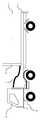
図1は、本発明の第1の実施形態に係るリーファコンテナの構造を表す背面図である。図2は、本発明の第1の実施形態に係るリーファコンテナをトラックに載置した状態を表す図である。図3は、本発明の第1の実施形態に係るリーファコンテナを電力供給装置に接続した状態を表す図である。図4は、本発明の第1の実施形態に係る電力供給装置が、リーファコンテナに接続された状態を示す回路図である。(First embodiment)
FIG. 1 is a rear view showing the structure of a leafer container according to the first embodiment of the present invention. FIG. 2 is a diagram illustrating a state in which the leafer container according to the first embodiment of the present invention is placed on a truck. FIG. 3 is a diagram illustrating a state in which the leafer container according to the first embodiment of the present invention is connected to the power supply device. FIG. 4 is a circuit diagram showing a state in which the power supply device according to the first embodiment of the present invention is connected to the reefer container.
リーファコンテナ1は、奥行きが高さ及び幅より長い直方体状のコンテナ本体10と、このコンテナ本体10に装備され、少なくとも温度調整手段21及び換気手段22を備えてあるリーファ20と、外部から電力を受電してリーファ20へ電力を供給する受電部30と、を備えている。リーファ20と受電部30はリーファコンテナ1の背面外側に設けてある。一方、リーファコンテナ1の正面には扉13を設けてある。 The reefer container 1 includes a rectangular
本実施形態におけるリーファ20は、リーファ20は温度調整装置(温度調整手段)21を備えてある。温度調整装置21は、少なくとも、ある期間温度を記録できる温度計24と、圧縮機25と、凝縮器が付加されたファン26と、ファン26を駆動するモータ27と、コンテナ本体10内の温度調節をするサーモスタット装置(図示しない)と、を備えてある。一般的に言われるエアーコンディショナの機能を有するものであれば良い。 The
続いて、換気装置(換気手段)22を備えてある。換気装置22は通常は閉じた状態であるが、換気装置22の開閉戸28を左右に移動させることにより、換気装置22が開いた状態にすることができる。換気装置22には換気扇(図示しない)が設けられており、開閉戸28で換気装置22が開いた状態になると換気扇を用いて換気をすることができ、この換気によって、湿度やエチレンガスの濃度を調整することができる。 Subsequently, a ventilation device (ventilation means) 22 is provided. The
本実施形態における受電部30もリーファ20内に設けてあり、受電部30には電源コード31の収容部が用意されており、ここに電源コード31が収容されている。このリーファコンテナ1はAC400V入力である。さらに、背面外部には、マイクロ・プロセッサが内蔵された制御装置(制御手段)23を備え、この制御装置23で温度調整装置21及び換気装置22を制御する。 The
以上のように構成されたリーファコンテナ1は本来の目的である一定の温度の状態で輸送することは可能である。図2でそれを示してある。図2では、トラック80の後部にトレーラ81を設けてあり、このトレーラ81の上にリーファコンテナ1を載せることができる。トレーラ81に載置したリーファコンテナ1は、前記の通り、リーファコンテナ1の背面に電源コード31を接続してあり、電源コード31の先端にはAC400V入力のプラグを設けてある。 The leafer container 1 configured as described above can be transported at a constant temperature, which is the original purpose. This is shown in FIG. In FIG. 2, a trailer 81 is provided at the rear portion of the truck 80, and the leafer container 1 can be placed on the trailer 81. As described above, the reefer container 1 placed on the trailer 81 is connected to the
リーファコンテナ1を運ぶトラック80の運転台82の後部には、電源設備(図示しない)が設けられており、リーファコンテナ1の電源コード31の先端に設けてあるプラグは、運転台82の後部に設けられた電源設備に接続し、そこからリーファコンテナ1へ電力を供給することができる。 A power supply facility (not shown) is provided at the rear of the
続いて、リーファコンテナ1を輸送する過程において、リーファコンテナ1を一輸送手段から別の輸送手段に移すまでの間、リーファコンテナ1がコンテナターミナル、コンテナヤード、貨物駅などで待機する時間の間に、本発明の第1の実施形態に係る電力供給装置に接続した場合について説明する。 Subsequently, in the process of transporting the reefer container 1, during the time when the reefer container 1 waits at the container terminal, container yard, cargo station, etc., until the reefer container 1 is moved from one transport means to another transport means. The case where it connects with the electric power supply apparatus which concerns on the 1st Embodiment of this invention is demonstrated.
先ず、電気的構成について説明する。本実施例に係る電力供給装置50は、リーファコンテナ1のリーファ20に電力を供給するための電力供給部51を設けてある。また、電力供給部51と電力源60とを接続可能とし、電力源60から電力供給部51へ電力を供給するために直流電力から交流電力に変換するインバータユニット52を設けてある。本実施例におけるインバータユニット52は直流から交流に電力変換する機能を有し、リーファ20にAC400Vを供給できるものであれば、インバータの形式は問わない。 First, the electrical configuration will be described. The
続いて、本実施例に係る電力供給装置50に接続する電力源60について説明する。電力については、商用電源であっても良いが、上記の課題で述べたように、リーファコンテナ1を一輸送手段から別の輸送手段に移すまでの間、リーファコンテナがコンテナターミナル、コンテナヤード、貨物駅などで待機する時間があるが、その間は電力源を有しないため、その間に、収容物の変形や腐食がおきて、収容物が商品として価値が無くなることが課題である。本願は商用電源が無いところでも、リーファコンテナ1を一輸送手段から別の輸送手段に移すまでの待機時間もリーファ20に電力を供給することができるようにしたものである。 Next, the power source 60 connected to the
電力源60の形式は問わないが、実施例として、太陽光、風力その他再生可能エネルギーを利用した電力源が想定される。本実施例においては、太陽光発電61を挙げる。但し、埠頭のように風が比較的強く、昼夜関係なく発電できる風力発電を利用することも想定でき、その他その土地柄に応じた再生可能エネルギーを利用した電力源であっても良い。風力発電の場合は、太陽光発電と異なり、交流を出力する。そのため、風力発電機と接続する場合、インバータユニット52は直流から交流に電力変換する機能に加え、又はこれと替わって、交流の電圧変換する機能を有する必要がある。 The type of the power source 60 is not limited, but a power source using sunlight, wind power, or other renewable energy is assumed as an example. In this embodiment, a
なお、再生可能エネルギーは、太陽光、風力、水力、地熱、太陽熱、自然界に存する熱、バイオマスをエネルギー源とするものをいうが、その他再生可能なエネルギー源であれば、本発明に全て含まれる。 Renewable energy refers to solar energy, wind power, hydropower, geothermal energy, solar heat, heat existing in the natural world, or biomass as an energy source, but any other renewable energy source is included in the present invention. .
続いて、太陽光、風力その他再生可能エネルギーを利用した電力源以外にも、電気を利用した車両に搭載された二次電池を電力源として利用することも可能である。本実施例においては、電気自動車62に搭載されたバッテリを挙げているが、これ以外に、プラグインハイブリッド車に搭載されたバッテリや、燃料電池を搭載した自動車に搭載された燃料電池などが想定できる。 Subsequently, in addition to a power source using sunlight, wind power, or other renewable energy, a secondary battery mounted on a vehicle using electricity can be used as a power source. In the present embodiment, a battery mounted on the
電気自動車62は当然移動可能であり、リーファコンテナ1に電力を供給する際に、リーファコンテナ1の近くまで電気自動車62を移動させ、リーファコンテナがコンテナターミナル、コンテナヤード、貨物駅などで待機する時間が終了すれば、別のリーファコンテナ1に移動することができる。また、電気自動車62は、本実施例に係る電力供給装置50を介して、リーファ20に電力を供給できるものであれば良い。 The
また、本実施例においては、太陽光発電61と電気自動車62に搭載されたバッテリとを併用して用いられるようにしてある。太陽光発電61が利用できない深夜においては電気自動車62に搭載されたバッテリを電力源として用いることができる。 Further, in this embodiment, the
続いて、本実施例においては、インバータユニット52にバッテリ70を接続してある。インバータユニット52は前述する通り、電力源60からリーファ20に対しては、直流から交流に電力変換して電力を供給する機能を有する。さらに、本実施例におけるインバータユニット52は、電力源60とバッテリ70との間においては、コンバータとしての機能を有し、電力源60からリーファ20に電力を供給している間、電力源60からバッテリ70に電力供給できるようにしてある。 Subsequently, in this embodiment, a
さらに、バッテリ7からリーファ20に対しては、他の電力源60と同様に、直流から交流に電力変換して電力を供給することができるようにしてある。なお、バッテリ70は電力源60から供給される電力を蓄電することができ、バッテリ70からインバータユニット52を介してリーファ20に電力を供給できれば、何でも良いが、リチウムイオン電池だと狭い場所で大容量の電力を蓄電することができるので最適である。 Further, like the other power sources 60, power can be supplied from the battery 7 to the
以上のように構成されたリーファコンテナ1は、コンテナターミナルやコンテナヤードでは、リーファコンテナ1を複数個並べて待機させている。図3では横に2列にリーファコンテナ1を設けてあるが、並べ方については問わない。複数個並べたリーファコンテナ1は、前記の通りリーファコンテナ1の背面外側に電源コード収容部を設けてあり、その中に電源コード31を設けてある。電源コード31の先端にはAC400V入力のプラグを設けてあり、このプラグは、太陽光発電61や電気自動車62などの電力源60からからインバータユニット52を備えた電力供給装置50に接続し、電力供給装置50から各リーファ20に電力を供給する。 The leafer container 1 configured as described above waits with a plurality of leafer containers 1 arranged in a container terminal or a container yard. In FIG. 3, the leafer containers 1 are provided in two horizontal rows, but the arrangement is not limited. As described above, the plurality of reefer containers 1 are provided with the power cord accommodating portion on the outer rear side of the reefer container 1 and the
電力供給装置50から各リーファ20に電力を供給することにより、リーファコンテナ1を輸送する過程において、リーファコンテナ1を一輸送手段から別の輸送手段に移すまでの間、リーファコンテナ1がコンテナターミナル、コンテナヤード、貨物駅などで待機する時間においても、リーファ20に電力を供給することができる。 In the process of transporting the leafer container 1 by supplying power to each leafer 20 from the
また、電力源60からリーファ20に電力を供給している間において、バッテリ70にも電力を供給している。そのため、バッテリ70は蓄電される。これにより、電力源60からリーファ20に電力を供給できない時間帯にバッテリ70からリーファ20に電力を供給することができる。 In addition, while power is being supplied from the power source 60 to the
また、バッテリ70を外部で充電しておけば、電力源60を設けることができない場所においてもバッテリ70を電力源としてリーファ20に電力供給することができる。また、電力源60を設けることができる場所であっても、停電など非常事態により電力源60が利用できなくなっても、その間にバッテリ70を電力源としてリーファ20に電力供給することができる。以上より、従来よりも電力供給できない待機時間を減少させることができる。その結果、リーファコンテナ1内の農作物、青果品、生鮮品、化学工業品などの収容物の変形や腐食などを抑えることができ、目的地に行くまでに、収容物の鮮度を維持することができ、収容物が商品として価値を維持することができる。 Further, if the
本実施例ではインバータユニット52を設けた例について説明する。現段階ではリーファコンテナ1はAC400V入力であるため、インバータユニット52を設けてある。但し、将来的には直流入力のリーファコンテナも想定できる。この場合はインバータユニット52ではなく、少なくともコンバータの機能を有しておれば良い。また、交流入力のリーファコンテナと直流入力のリーファコンテナが混在することも想定できる。この場合は、インバータユニット52に該当するものが電力変換機能を有する電力変換ユニットであればよい。 In this embodiment, an example in which an
以上、本発明の実施形態について説明したが、本発明は、上述した実施形態に限定されるものではなく、本発明の要旨を逸脱しない範囲内で様々な変形や応用が可能である。 As mentioned above, although embodiment of this invention was described, this invention is not limited to embodiment mentioned above, A various deformation | transformation and application are possible within the range which does not deviate from the summary of this invention.
1 リーファコンテナ
10 コンテナ本体
20 リーファ
21 温度調整装置
22 換気装置
23 制御装置
24 温度計
25 圧縮機
26 ファン
27 モータ
28 開閉戸
30 受電部
31 電源コード
50 電力供給装置
51 電力供給部
52 インバータユニット
60 電力源
61 太陽光発電
62 電気自動車
70 バッテリDESCRIPTION OF SYMBOLS 1
Claims (6)
Translated fromJapaneseこのコンテナ本体に装備され、少なくとも温度調整手段を備えてあるリーファと、
外部から電力を受電して前記リーファへ電力を供給する受電部と、
を備えたリーファコンテナにおける電力供給装置であって、
前記リーファコンテナに電力を供給するための電力供給部と、
前記電力供給部と直流又は交流の電力源とを接続可能とし、前記電力源から前記電力供給部へ電力を供給するために直流から交流、交流から直流、又は電圧が異なる直流から直流、若しくは電圧が異なる交流から交流に変換する電力変換ユニットと、
を備えた、
ことを特徴とするリーファコンテナ用の電力供給装置。A box-shaped container body;
A leafer equipped on the container body and having at least a temperature adjusting means,
A power receiving unit that receives power from outside and supplies power to the leafer;
A power supply device in a reefer container comprising:
A power supply unit for supplying power to the leafer container;
The power supply unit can be connected to a DC or AC power source, and in order to supply power from the power source to the power supply unit, DC to AC, AC to DC, or DC to DC or voltage having different voltages A power conversion unit that converts alternating current into alternating current,
With
A power supply device for a leafa container.
ことを特徴とする請求項1記載のリーファコンテナ用の電力供給装置。As the power source, using electric power using renewable energy,
The power supply device for a leafer container according to claim 1.
ことを特徴とする請求項2に記載のリーファコンテナ用の電力供給装置。The renewable energy uses sunlight, wind power, hydropower, geothermal heat, solar heat, heat existing in nature, and biomass as an energy source.
The power supply device for a leafer container according to claim 2.
請求項1乃至3のいずれかに記載のリーファコンテナ用の電力供給装置。As the power source, a battery or a fuel cell mounted on a vehicle using electricity is used.
The power supply apparatus for leafers containers in any one of Claims 1 thru | or 3.
ことを特徴とする請求項1乃至4のいずれかに記載のリーファコンテナ用の電力供給装置。A battery capable of storing the power supplied from the power source is connectable to the power conversion unit, and the power conversion unit can store the power supplied from the power source in the battery. In addition, it is possible to supply power from the battery to the power supply unit via the power conversion unit.
The power supply device for a leafer container according to any one of claims 1 to 4.
このコンテナ本体に装備され、少なくとも温度調整手段を備えてあるリーファと、
外部から電力を受電して前記リーファへ電力を供給する受電部と、
を備えたリーファコンテナにおいて、
前記リーファコンテナを輸送する過程において、一輸送手段から別の輸送手段に移す待機時間の間、請求項1乃至4のいずれかに記載のリーファコンテナ用の電力供給装置を用いて前記リーファコンテナに電力を供給する、
ことを特徴とするリーファコンテナの電力供給方法。A box-shaped container body;
A leafer equipped on the container body and having at least a temperature adjusting means,
A power receiving unit that receives power from outside and supplies power to the leafer;
In the leafa container with
5. In the process of transporting the leafer container, electric power is supplied to the leafer container using the power supply device for the leafer container according to claim 1 during a standby time for shifting from one transportation means to another transportation means. Supply,
A method for supplying power to a leafa container.
Priority Applications (1)
| Application Number | Priority Date | Filing Date | Title |
|---|---|---|---|
| JP2016070387AJP2017184516A (en) | 2016-03-31 | 2016-03-31 | Power supply device for reefer container, and power supply method for reefer container |
Applications Claiming Priority (1)
| Application Number | Priority Date | Filing Date | Title |
|---|---|---|---|
| JP2016070387AJP2017184516A (en) | 2016-03-31 | 2016-03-31 | Power supply device for reefer container, and power supply method for reefer container |
Publications (1)
| Publication Number | Publication Date |
|---|---|
| JP2017184516Atrue JP2017184516A (en) | 2017-10-05 |
Family
ID=60007311
Family Applications (1)
| Application Number | Title | Priority Date | Filing Date |
|---|---|---|---|
| JP2016070387APendingJP2017184516A (en) | 2016-03-31 | 2016-03-31 | Power supply device for reefer container, and power supply method for reefer container |
Country Status (1)
| Country | Link |
|---|---|
| JP (1) | JP2017184516A (en) |
Cited By (3)
| Publication number | Priority date | Publication date | Assignee | Title |
|---|---|---|---|---|
| CN108512298A (en)* | 2018-05-21 | 2018-09-07 | 中铁第四勘察设计院集团有限公司 | A kind of railway stockyard frozen products insulated container power supply system |
| WO2020161763A1 (en)* | 2019-02-04 | 2020-08-13 | 三菱電機株式会社 | Low-temperature logistics system |
| WO2021234059A1 (en)* | 2020-05-20 | 2021-11-25 | Ineo Urban Transportation Solutions | Charging station for electric vehicle fleets |
Citations (3)
| Publication number | Priority date | Publication date | Assignee | Title |
|---|---|---|---|---|
| JP2000085449A (en)* | 1998-09-09 | 2000-03-28 | Mitsubishi Motors Corp | Automotive cooling system |
| JP2003097873A (en)* | 2001-09-26 | 2003-04-03 | Mitsubishi Heavy Ind Ltd | Operation method for refrigeration unit for land transportation, and refrigeration unit for land transportation |
| JP2014093906A (en)* | 2012-11-06 | 2014-05-19 | Full Time System:Kk | Power supply device and emergency power source provision system |
- 2016
- 2016-03-31JPJP2016070387Apatent/JP2017184516A/enactivePending
Patent Citations (3)
| Publication number | Priority date | Publication date | Assignee | Title |
|---|---|---|---|---|
| JP2000085449A (en)* | 1998-09-09 | 2000-03-28 | Mitsubishi Motors Corp | Automotive cooling system |
| JP2003097873A (en)* | 2001-09-26 | 2003-04-03 | Mitsubishi Heavy Ind Ltd | Operation method for refrigeration unit for land transportation, and refrigeration unit for land transportation |
| JP2014093906A (en)* | 2012-11-06 | 2014-05-19 | Full Time System:Kk | Power supply device and emergency power source provision system |
Cited By (6)
| Publication number | Priority date | Publication date | Assignee | Title |
|---|---|---|---|---|
| CN108512298A (en)* | 2018-05-21 | 2018-09-07 | 中铁第四勘察设计院集团有限公司 | A kind of railway stockyard frozen products insulated container power supply system |
| CN108512298B (en)* | 2018-05-21 | 2023-06-20 | 中铁第四勘察设计院集团有限公司 | Railway yard refrigerated container power supply system |
| WO2020161763A1 (en)* | 2019-02-04 | 2020-08-13 | 三菱電機株式会社 | Low-temperature logistics system |
| JPWO2020161763A1 (en)* | 2019-02-04 | 2021-11-04 | 三菱電機株式会社 | Low temperature logistics system |
| WO2021234059A1 (en)* | 2020-05-20 | 2021-11-25 | Ineo Urban Transportation Solutions | Charging station for electric vehicle fleets |
| FR3110787A1 (en)* | 2020-05-20 | 2021-11-26 | Ineo Urban Transportation Solutions | CHARGING STATION FOR ELECTRIC VEHICLE FLEETS |
Similar Documents
| Publication | Publication Date | Title |
|---|---|---|
| US20230174008A1 (en) | Electric mobile refrigeration unit | |
| US20190222054A1 (en) | Energy supply arrangement | |
| CN102910107A (en) | Solar hybrid power refrigerating device | |
| US20180245825A1 (en) | Battery powered hybrid transport refrigeration unit | |
| US11135893B2 (en) | Transport refrigeration unit (TRU) direct current (DC) architecture | |
| US20150316301A1 (en) | Method and system for charging a transport refrigeration system | |
| JP2017184516A (en) | Power supply device for reefer container, and power supply method for reefer container | |
| GB2463098A (en) | Shipping container with photovoltaic panel | |
| MX2007003643A (en) | Temperature controlled air cargo container transport dolly. | |
| CN105102324A (en) | Absorption cooling for aircraft dining cars and compartments | |
| CN204384028U (en) | A kind of Vehicular solar cold chain counter | |
| BR112022010440A2 (en) | MOBILE STATION TO PERFORM AERIAL SPRAYING OPERATIONS BY UNmanned AERIAL VEHICLES | |
| Sheikh et al. | Optimized energy management of seaports with integrated AMP technology and DC microgrid | |
| CN210200775U (en) | Miniature container for ship battery system | |
| US10892633B2 (en) | Methods and systems for automotive type transient protection of a solar charge source | |
| NL2004885C2 (en) | System for providing a data centre. | |
| Pietracho et al. | Electrical propulsion systems in vehicles–an overview of solutions | |
| US12212138B2 (en) | Solar power distribution and control system for movable storage containers | |
| CN203260929U (en) | Box-type energy storage transformer substation | |
| CN110729750A (en) | A self-powered warehouse energy storage system based on photovoltaic power generation | |
| Leinonen | Smart and Secure Energy Solutions for Future Mobility: Results of the Energy ECS Project at Lapland University of Applied Sciencesity of Applied Sciences | |
| CN205440236U (en) | Freight train with freezer | |
| CN214154038U (en) | Intelligent micro-grid power station with air conditioner anti-collision function | |
| EP4227606A1 (en) | Autonomous refrigerated container for storage and thermostatted transport of products | |
| RU169516U1 (en) | REFRIGERATOR CONTAINER |
Legal Events
| Date | Code | Title | Description |
|---|---|---|---|
| A621 | Written request for application examination | Free format text:JAPANESE INTERMEDIATE CODE: A621 Effective date:20180705 | |
| A977 | Report on retrieval | Free format text:JAPANESE INTERMEDIATE CODE: A971007 Effective date:20190329 | |
| A131 | Notification of reasons for refusal | Free format text:JAPANESE INTERMEDIATE CODE: A131 Effective date:20190507 | |
| A02 | Decision of refusal | Free format text:JAPANESE INTERMEDIATE CODE: A02 Effective date:20191112 |