JP2017182595A - Drive support method and drive support apparatus - Google Patents
Drive support method and drive support apparatusDownload PDFInfo
- Publication number
- JP2017182595A JP2017182595AJP2016071239AJP2016071239AJP2017182595AJP 2017182595 AJP2017182595 AJP 2017182595AJP 2016071239 AJP2016071239 AJP 2016071239AJP 2016071239 AJP2016071239 AJP 2016071239AJP 2017182595 AJP2017182595 AJP 2017182595A
- Authority
- JP
- Japan
- Prior art keywords
- image
- symbol
- host vehicle
- icon
- displayed
- Prior art date
- Legal status (The legal status is an assumption and is not a legal conclusion. Google has not performed a legal analysis and makes no representation as to the accuracy of the status listed.)
- Granted
Links
Images


Landscapes
- Closed-Circuit Television Systems (AREA)
- Traffic Control Systems (AREA)
- Rear-View Mirror Devices That Are Mounted On The Exterior Of The Vehicle (AREA)
Abstract
Translated fromJapaneseDescription
Translated fromJapanese本発明は、運転支援方法及び運転支援装置に関する。 The present invention relates to a driving support method and a driving support device.
例えば、特許文献1には、車両走行中に高速道路への合流や車線変更を実行する際に、変更後の車線に自車両が進入する進入スペースが有るか否かを判断し、進入スペースが存在する場合には、バックミラーに表示される後方像に進入スペースを示す画像を重畳することにより、乗員に対して車線変更し易いように運転を支援する技術が開示されている。 For example, Patent Document 1 determines whether or not there is an entry space in which the host vehicle enters the lane after the change when performing a merge to an expressway or a lane change while the vehicle is running. When it exists, the technique which assists a driving | operation so that it is easy to change a lane with respect to a passenger | crew by superimposing the image which shows approach space on the back image displayed on a rear-view mirror is disclosed.
しかしながら、上述した特許文献1に開示された技術では、バックミラーに表示される後方像の路面上に進入スペースを重畳して表示するものの、路面の映像は車両の走行に伴って変化するのに対し、進入スペースを示す画像には変化が生じない。このため、実際に乗員が視認すると、進入スペースが重畳された後方像に違和感が生じてしまうという問題があった。 However, in the technique disclosed in Patent Document 1 described above, although the approach space is superimposed on the road surface of the rear image displayed on the rearview mirror, the road image changes as the vehicle travels. On the other hand, no change occurs in the image showing the entry space. For this reason, when a passenger | crew actually visually recognized, there existed a problem that an uncomfortable feeling will arise in the rear image on which the approach space was superimposed.
本発明は、このような従来の課題を解決するためになされたものであり、その目的とするところは、乗員に違和感を感じさせること無く運転支援用の画像を表示することができる運転支援方法、及び運転支援装置を提供することにある。 The present invention has been made in order to solve such a conventional problem, and an object of the present invention is to provide a driving support method capable of displaying an image for driving support without making the passenger feel uncomfortable. And providing a driving support device.
上記目的を達成するため、本発明の一態様は、自車両の車速を取得し、車速に応じて記号が移動する運転支援用の仮想画像を生成し、仮想画像を自車両の周囲像に重畳して表示する。 In order to achieve the above object, according to one aspect of the present invention, a vehicle speed of a host vehicle is acquired, a virtual image for driving support in which a symbol moves according to the vehicle speed, and the virtual image is superimposed on a surrounding image of the host vehicle. And display.
本発明の一態様によれば、運転支援用の仮想画像上で、車速に応じて記号が移動するので、乗員に違和感を感じさせること無く運転支援用の画像を表示することができる。 According to one aspect of the present invention, the symbol moves in accordance with the vehicle speed on the driving assistance virtual image, so that the driving assistance image can be displayed without causing the occupant to feel uncomfortable.
以下、本発明の実施形態を図面に基づいて説明する。
[第1実施形態の説明]
図1は、本発明の第1実施形態に係る運転支援装置の構成を示すブロック図である。図1に示すように、この運転支援装置101は、自車両に搭載される車速センサ31より出力される車速データ、舵角センサ32より出力される舵角データ、ウィンカ33の操作信号、及びカメラ35で撮像される周囲画像に基づいて、バックミラー34に映る後方像(周囲像)に運転支援用のアイコンを重畳する。例えば、車線変更時に自車両が進入可能な領域を誘導スペースとして表示し乗員の車線変更操作を支援する。Hereinafter, embodiments of the present invention will be described with reference to the drawings.
[Description of First Embodiment]
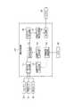
FIG. 1 is a block diagram showing the configuration of the driving support apparatus according to the first embodiment of the present invention. As shown in FIG. 1, the
図1に示すように、運転支援装置101は、自車両の車速及び舵角に基づいて進行方向を検出する進行方向検出回路11と、カメラ35で撮像した画像に基づいて自車両の周囲を走行する車両を検出する周囲環境検出回路12を備えている。更に、誘導スペース設定回路13、重畳アイコン設定回路14、記号設定回路15、記号フロー設定回路16、路面アイコン表示制御回路17、及びバックミラー34の鏡面に画像を重畳表示するための表示画面18を備えている。As shown in FIG. 1, the
誘導スペース設定回路13は、周囲環境検出回路12で検出した周囲車両の存在位置に基づいて、自車両の誘導スペースを決定する。例えば、自車両が高速道路の加速車線を走行しており、走行車線(右側の車線)へ車線変更する場合に、走行車線を走行中の他車両間の車間距離を演算する。そして、自車両が進入するための十分なスペースが存在すると判断した場合に、この車間となる路面を誘導スペースに決定する。なお、誘導スペースの演算方法は周知の技術であるので詳細な説明を省略する。 The guidance space setting
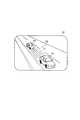
重畳アイコン設定回路14は、誘導スペース設定回路13で設定した誘導スペースに重畳表示するアイコンの大きさ、形状を決定する。図3は、自車両の右側に設けられるバックミラー34に表示される後方像を示す説明図である。図3に示すように、バックミラー34に、走行車線を走行する複数の他車両が後方像として表示されている際に、他車両間の誘導スペースに重畳表示するアイコンQ1の大きさ、形状を決定する。アイコンQ1を表示画面18に表示することにより、バックミラー34に映る後方像に重畳して視認される。従って、アイコンQ1は運転支援用の仮想画像の一例である。 The superimposed
記号設定回路15は、重畳アイコン設定回路14で決定したアイコンQ1の領域内に表示する記号を設定する。ここで、「記号」とは、走行中の車両周囲の流れを示すもので、アイコンQ1の領域内に表示する各種の模様(例えば、波模様、グラデーション、肌理、木目など)、マーク(例えば、三角マーク、四角マークなど)、等により示される。また、記号は必ずしも、模様やマークに限定される必要はなく、疎らに見えるものであれば何でも良い。この記号は、車両走行に併せて動かすことにより、後方像に写る車両周囲の動きに同化させることができる。これにより、乗員は、後方像に対する違和感を抑制することができる。本実施形態では、路面上の誘導スペースを表示するので、アスファルトの模様を記号として設定する。尚、本実施形態では、アスファルトの模様を記号として設定したが、必ずしもこれに限定せず、道路上の白線や、路肩など、車両の走行に併せて動いて見えるものを対象物としても良い。The symbol setting
記号フロー設定回路16は、進行方向検出回路11で検出した自車両の進行方向、及び記号設定回路15で設定した記号に基づいて、アイコンQ1の領域内に表示する記号の大きさ、記号の移動方向、及び記号の移動速度を設定する。具体的には、自車両から誘導スペースとして表示するアイコンQ1までの距離が近いほど記号が大きくなるように表示する。このため、自車両の乗員は、記号の大きさを認識することにより自車両から誘導スペースまでの距離を認識し易くなる。 The symbol
また、記号フロー設定回路16は、自車両の後方に移動する方向に記号を表示する。即ち、図3に示すアイコンQ1の領域内に表示する記号が、矢印Y1の方向に移動するようにアイコンQ1の画像を設定する。更に、自車両の走行速度が速いほど、記号の移動速度が速くなるようにアイコンQ1の画像を設定する。これに加えて、自車両の舵角に応じた方向に記号が移動するようにアイコンQ1の画像を設定する。即ち、自車両の走行速度に応じた速度で記号を移動させ、且つ舵角に応じた方向に記号を移動させることにより、自車両の動きに適合するように記号が移動するので、乗員に対して違和感なく誘導スペースを認識させることができる。例えば、自車両が右に舵角を切った場合は、記号を自車両に対して左後方に移動する方向に表示する。 Moreover, the symbol
路面アイコン表示制御回路17は、記号フロー設定回路16で設定された記号を含むアイコンQ1を、表示画面18に表示する。路面アイコン表示制御回路17は、自車両の車速に応じて記号が移動する仮想画像を生成する仮想画像生成回路の一例である。 The road surface icon
表示画面18は、バックミラー34の鏡面裏側に搭載されている。従って、表示画面18の適所にアイコンQ1を表示することにより、バックミラー34に表示される後方像にアイコンQ1を重畳することができる。なお、表示画面18として、例えば自車両のサイドウィンドに表示し、乗員のアイポイントとバックミラーを結ぶ線上の適所に路面アイコンを表示することも可能である。即ち、表示画面18或いはサイドウィンドは、自車両に搭載されて周囲情報を表示する表示部の一例である。 The
なお、図1に示す運転支援装置101は、例えば、中央演算ユニット(CPU)や、RAM、ROM、ハードディスク等の記憶手段からなる一体型のコンピュータ、及びディスプレイ装置で構成することができる。 The driving
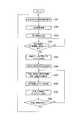
次に、第1実施形態に係る運転支援装置101の作用を、図2に示すフローチャートを参照して説明する。初めに、図2のステップS11において、進行方向検出回路11は、ウィンカ33が操作されたか否かを判断する。この処理では、ウィンカ33を操作したことを示す操作信号により、車線変更の意思があるか否かを確認しており、例えば、右方向にウィンカ33が操作されている場合には、右方向の車線に車線変更する意思があるものと判断する。 Next, the operation of the driving
ウィンカ33が操作されたと判断された場合には(ステップS11でYES)、ステップS12において、周囲環境検出回路12は、カメラ35で撮像される自車両の周囲画像を取得する。この周囲画像には、自車両の後方を走行する他車両の画像が含まれる。 If it is determined that the
ステップS13において、誘導スペース設定回路13は、ステップS12で取得した周囲画像に基づいて、自車両が進入しようとする車線(例えば、高速道路の走行車線)を走行する複数の他車両の車間距離を演算し、自車両が車線変更により進入するスペースが有るか否かを判断する。そして、進入するスペースが存在する場合には、このスペースを誘導スペースとして認識する。 In step S13, the guidance
ステップS14において、重畳アイコン設定回路14は、ステップS13の処理で認識した誘導スペースに重畳するアイコンを決定する。例えば、アイコンの形状を長方形とし、更に誘導スペースの広さに応じて長方形の大きさを決める。 In step S14, the superimposed
ステップS15において、記号設定回路15は、アイコンの内部に表示する記号、及び記号の大きさを設定する。本実施形態では、アスファルトの記号を用いる。また、誘導スペースまでの距離に応じて記号の大きさを設定する。即ち、カメラ35で撮像された画像に基づき、自車両から誘導スペースまでの距離を求めることができるので、誘導スペースまでの距離が短いほど記号が大きくなるように設定する。こうすることにより、走行車線上に見えるアスファルトの映像と同等の記号を表示することができ、遠近感を持たせることができる。 In step S15, the
ステップS16において、記号フロー設定回路16は、アイコンの内部に表示する記号の移動方向、移動速度を設定する。具体的には、記号が走行車線の後方に向けて移動するようにアイコン内に表示する複数の記号を移動させる。この際、自車両の走行速度が速いほど、記号の移動速度が速くなるようにする。また、ステアリングが操舵された場合には、この操舵方向の反対となる方向に記号を移動させる。こうすることにより、実際の走行速度、操舵方向に適合する速度で記号が移動することになり、乗員に対して違和感を感じさせることなく誘導スペースを認識させることができる。 In step S16, the symbol
ステップS17において、路面アイコン表示制御回路17は、表示画面18上の、バックミラー34に表示される後方像の誘導スペースに相当する領域に、アイコンを表示する。その結果、図3に示すように2台の他車両V1、V2間のスペースにアイコンQ1が表示される。従って、自車両が車線変更する際に、進入しようとする車線上に誘導スペースを示すアイコンQ1が表示され、円滑な車線変更を支援できる。 In step S <b> 17, the road surface icon
ステップS18において、進行方向検出回路11は、ウィンカ33がオフとされたか否かを判断する。ウィンカ33がオフとされた場合には、ステップS20においてアイコンQ1の表示を終了する。 In step S18, the traveling
一方、ウィンカ33がオフとされない場合には、ステップS19において、進行方向検出回路11は、自車両の車速或いは舵角が変化したか否かを判断する。車速或いは舵角が変化した場合には、ステップS12に処理を戻し、車速及び舵角が変化しない場合には、ステップS16に処理を戻す。 On the other hand, if the
このようにして、第1実施形態に係る運転支援装置101では、自車両が車線変更する際に、変更後の車線(例えば、高速道路の走行車線)に誘導スペースを設定し、該誘導スペースに複数の記号を有するアイコンQ1を表示する。更に、該アイコンQ1に含まれる記号を移動させる。従って、誘導スペースにアイコンQ1を表示する際に、該アイコンQ1が走行車線の路面と同化して見えることになる。このため、誘導スペースを示す路面を認識し易くなり、従来のようにアイコンが浮いて見える等の問題の発生を回避することができる。その結果、高速道路の加速車線から走行車線へ侵入する場合等の車線変更を円滑に実行することが可能となる。 Thus, in the driving
また、自車両の車速が速いほど、アイコンQ1内の記号の移動速度が速くなるように表示する。更に、自車両が操舵されているときには、操舵方向と反対側に記号が移動するように表示する。従って、自車両の走行速度、操舵状況に応じた違和感の無いアイコンQ1を表示することができ、乗員に対して誘導スペースを容易に認識させることが可能となる。 Further, the faster the vehicle speed of the host vehicle, the faster the moving speed of the symbol in the icon Q1 is displayed. Further, when the host vehicle is being steered, the symbol is displayed so as to move to the side opposite to the steering direction. Therefore, it is possible to display the icon Q1 without a sense of incongruity according to the traveling speed of the host vehicle and the steering situation, and it is possible to make the occupant easily recognize the guidance space.
更に、自車両から誘導スペースまでの距離が短いほど記号を大きく表示するので、誘導スペースまでの距離感を認識し易くすることができる。 Furthermore, since the symbol is displayed larger as the distance from the host vehicle to the guidance space is shorter, the sense of distance to the guidance space can be easily recognized.
なお、上記した第1実施形態では、自車両のウィンカ33の操作を検出し、ウィンカ33が操作された際に、アイコンを表示する例について説明したが、本実施形態はこれに限定されず、ウィンカ33の操作に関わらず、常に自車両の走行車線に隣接する車線に誘導スペースを示すアイコンQ1を表示することも可能である。 In the first embodiment described above, the operation of the
[第1実施形態の変形例の説明]
上述した第1実施形態では、自車両が進入しようとする走行車線の後方を走行する他車両の車間のスペースを検出して、自車両が進入可能なスペースが存在する場合に、これを誘導スペースとして認識し、この誘導スペースを示すアイコンQ1を重畳表示する例について説明した。[Description of Modified Example of First Embodiment]
In the first embodiment described above, when a space between other vehicles traveling behind the traveling lane to which the host vehicle is to enter is detected and there is a space in which the host vehicle can enter, this space is guided. As described above, the example in which the icon Q1 indicating the guidance space is superimposed and displayed has been described.
これに対して、変形例に係る運転支援装置では、走行車線の後方を走行する各他車両どうしの間の車間領域を検出し、この車間領域にアイコンを重畳表示する。即ち、車間距離の長短に関わらず、車間領域としてアイコンを表示する。そして、自車両が車間領域に進入できるだけのスペースが存在する場合に、この車間領域を誘導スペースとして認識する。この際、誘導スペースと認識した車間領域の色と、誘導スペースと認識しない車間領域の色を変更して表示する。 On the other hand, in the driving support device according to the modified example, an inter-vehicle area between the other vehicles traveling behind the traveling lane is detected, and an icon is superimposed on the inter-vehicle area. That is, the icon is displayed as the inter-vehicle area regardless of the length of the inter-vehicle distance. Then, when there is enough space for the host vehicle to enter the inter-vehicle area, the inter-vehicle area is recognized as the guidance space. At this time, the color of the inter-vehicle area recognized as the guidance space and the color of the inter-vehicle area not recognized as the guidance space are changed and displayed.
例えば、車間距離が長く、誘導スペースとして認識された場合には、この誘導スペースを緑色のアイコンで表示する。一方、車間距離が短く、誘導スペースとして認識しない車間領域については、赤色のアイコンで表示する。このような表示方法を採用することにより、乗員に対して他車両の車間領域を認識させることができる。 For example, when the inter-vehicle distance is long and recognized as a guidance space, the guidance space is displayed with a green icon. On the other hand, an inter-vehicle area that has a short inter-vehicle distance and is not recognized as a guidance space is displayed with a red icon. By adopting such a display method, the occupant can recognize the inter-vehicle area of the other vehicle.
更に、他車両間のスペースは、時々刻々と変化し、スペースが広がって誘導スペースと認識される場合がある。このような場合には、アイコンの表示色を赤から緑に変化させることにより、誘導スペースを乗員にとって認識し易い態様で表示することが可能となる。 Furthermore, the space between other vehicles may change from moment to moment, and the space may be widened and recognized as a guidance space. In such a case, by changing the display color of the icon from red to green, the guidance space can be displayed in a manner that is easily recognized by the occupant.
アイコンの表示色以外でも、アイコンの種類によって自車両が進入可能な誘導スペースであるか、或いは進入困難な車間領域であるかを区別することが可能である。例えば、進入困難な車間領域である場合には「×」の記号を表示し、進入可能な誘導スペースに変化した場合には、アスファルトの記号に変更することも可能である。 In addition to the display color of the icon, it is possible to distinguish whether the vehicle is a guidance space where the host vehicle can enter or an inter-vehicle area where entry is difficult. For example, the symbol “x” can be displayed in the case of an inter-vehicle area where entry is difficult, and the symbol can be changed to an asphalt symbol when the vehicle is changed to a guide space where entry is possible.
このように、変形例に係る運転支援装置では、他車両どうしの間を車間領域として設定し、この車間領域に対応する表示画面18上の位置にアイコンを表示する。その後、この車間領域が広がって誘導スペースとして認識された場合には、アイコンの色や記号の種類を変更する。即ち、周囲状況に応じて記号の色、または種類の少なくとも一方を変更することにより、誘導スペースを乗員に認識し易くする。従って、乗員は、誘導スペースをより認識し易い態様で視認することが可能となる。 As described above, in the driving support device according to the modification, the space between the other vehicles is set as the inter-vehicle region, and the icon is displayed at a position on the
[第2実施形態の説明]
次に、本発明の第2実施形態について説明する。図4は、第2実施形態に係る運転支援装置102、及びその周辺機器の構成を示すブロック図である。図4に示すように、この運転支援装置102は、前述した第1実施形態と同様に、進行方向検出回路11、周囲環境検出回路12、誘導スペース設定回路13、重畳アイコン設定回路14、記号設定回路15、記号フロー設定回路16、及び路面アイコン表示制御回路17を備えている。更に、画像合成回路25、及びディスプレイ22を備えている。[Description of Second Embodiment]
Next, a second embodiment of the present invention will be described. FIG. 4 is a block diagram illustrating a configuration of the driving
周囲環境検出回路12は、自車両の周囲画像に基づいて取得される自車両の後方画像から、自車両の後方を走行する他車両の位置を検出する。即ち、自車両には前方カメラ21a、左側カメラ21b、右側カメラ21c、及び後方カメラ21dの4台のカメラが搭載されており、各カメラ21a〜21dで撮像された画像は、視点変換回路23にて視点変換される。画像生成回路24は、視点変換された画像に基づいて後方画像を生成し、生成した後方画像を周囲環境検出回路12、及び画像合成回路25に出力する。周囲環境検出回路12は、この後方画像に基づいて、後方を走行する他車両の位置を検出する。なお、各カメラ21a〜21dで撮像された画像から任意の視点となる画像を生成する視点変換の技術は周知であるので、説明を省略する。 The ambient
画像合成回路25は、画像生成回路24で生成された後方画像に、路面アイコン表示制御回路17で生成したアイコンを重畳し、例えば、自車両のインパネ近傍に設けられるディスプレイ22に表示する。なお、路面アイコン表示制御回路17にて誘導スペースを示すアイコンを生成する処理は、前述した第1実施形態と同様である。ここで、ディスプレイ22は、自車両に搭載されて周囲情報を表示する表示部の一例である。 The
そして、第2実施形態では、4台のカメラ21a〜21dで撮像した画像に基づいて自車両の後方画像を生成し、更にこの後方画像に誘導スペースを示すアイコンを重畳してインパネに設けられるディスプレイ22に表示することにより、車線変更するスペースを乗員に認識させる。具体的には、図6に示すように、車両のインパネ近傍に搭載された後方画像表示用のディスプレイ22に、誘導スペースのアイコンQ1を合成した後方画像を表示する。 And in 2nd Embodiment, the back image of the own vehicle is produced | generated based on the image imaged with the four
次に、第2実施形態に係る運転支援装置102の処理手順を、図5に示すフローチャートを参照して説明する。初めに、図5のステップS31において、4台のカメラ21a〜21dで自車両の周囲を撮像し、周囲画像を取得する。 Next, a processing procedure of the driving
ステップS32において、視点変換回路23は、各カメラ21a〜21dで撮像された周囲画像を取得する。 In step S32, the
ステップS33において、画像生成回路24は、視点変換回路23より出力される画像に基づき自車両の後方画像を生成する。生成された後方画像を、画像合成回路25に出力する。また、視点変換回路23で生成される視点変換画像を、周囲環境検出回路12に出力する。周囲環境検出回路12は、この視点変換画像に基づいて、自車両の周囲画像を生成する。 In step S <b> 33, the
ステップS34において、誘導スペース設定回路13は、周囲画像に基づいて、自車両が進入しようとする車線(例えば、高速道路の走行車線)を走行する複数の他車両の車間距離を演算し、自車両が車線変更により進入するスペースが有るか否かを判断する。そして、進入するスペースが存在する場合には(ステップS34でYES)、このスペースを誘導スペースとして認識する。 In step S34, the guidance
ステップS35において、重畳アイコン設定回路14は、ステップS34の処理で認識した誘導スペースに重畳するアイコンを決定する。例えば、アイコンの形状を長方形とし、更に誘導スペースの広さに応じて長方形の大きさを決める。 In step S35, the superimposed
ステップS36において、記号設定回路15は、アイコン内部に表示する記号、及び記号の大きさを設定する。本実施形態では、アスファルトの記号を用いる。また、誘導スペースまでの距離に応じて記号の大きさを設定する。即ち、自車両の周囲画像に基づき、自車両から誘導スペースまでの距離を求めることができるので、誘導スペースまでの距離が短いほど記号が大きくなるように設定する。こうすることにより、走行車線上に見えるアスファルトの映像と同等の記号を表示することができ、乗員に遠近感を持たせることができる。 In step S36, the
ステップS37において、記号フロー設定回路16は、アイコンの内部に表示する記号の移動方向、移動速度を設定する。具体的には、記号が走行車線の後方に向けて移動するようにアイコン内に表示する複数の記号を移動させる。この際、自車両の走行速度が速いほど、記号の移動速度が速くなるようにする。また、ステアリングが操舵された場合には、この操舵方向の反対となる方向に記号を移動させる。こうすることにより、実際の走行速度、操舵方向に適合する速度で記号が移動することになり、乗員が違和感を感じることなく誘導スペースを認識できる。 In step S37, the symbol
ステップS38において、画像合成回路25は、画像生成回路24にて生成された後方画像に、路面アイコン表示制御回路17で生成された進入スペースのアイコンを合成する。その後、ステップS39において、図6に示すように、ディスプレイ22に表示される2台の他車両V3、V4間に進入スペースを示すアイコンQ2が表示される。従って、自車両が車線変更する際に、進入しようとする車線上に誘導スペースを示すアイコンQ2が表示され、円滑な車線変更を支援できる。 In step S <b> 38, the
ステップS40において、進行方向検出回路11は、車速或いは舵角が変化したか否かを判断し、車速或いは舵角が変化した場合にはステップS31に処理を戻し、車速及び舵角が変化しない場合には、ステップS37に処理を戻す。こうして、自車両のインパネ近傍に設けられるディスプレイ22に自車両の後方画像を表示し、且つこの後方画像に進入スペースを示すアイコンを重畳表示することができるのである。 In step S40, the traveling
このようにして、第2実施形態に係る運転支援装置102では、4台のカメラ21a〜21dで撮像される各画像から視点変換処理により後方画像を生成し、この後方画像にアイコンQ2を合成してディスプレイ22に表示する。従って、乗員は、ディスプレイ22に表示された後方画像を視認することにより、自車両が進入可能なスペースを容易に認識することができ、車線変更の操作を円滑に実行することが可能となる。 Thus, in the driving
また、インパネ近傍に設置したディスプレイ22に後方画像を表示し、更に誘導スペースを示すアイコンQ2を合成するので、視認性を向上させることができる。更に、アイコンQ2にはアスファルトの記号が表示され、更に、この記号が移動するので、乗員に対して違和感無く誘導スペースを認識させることができる。 Further, the rear image is displayed on the
更に、車速に応じて記号が移動し、且つ、操舵方向に応じて記号が移動するので、違和感の無い視認性を得ることができる。なお、第2実施形態においても前述した第1実施形態と同様に、ウィンカが操作されたことを条件としてアイコンを重畳するようにしてもよい。 Furthermore, since the symbol moves according to the vehicle speed and the symbol moves according to the steering direction, visibility without a sense of incongruity can be obtained. In the second embodiment, as in the first embodiment described above, icons may be superimposed on the condition that the blinker is operated.
[第3実施形態の説明]
次に、本発明の第3実施形態について説明する。図7は、第3実施形態に係る運転支援装置103、及びその周辺機器の構成を示すブロック図である。図7に示すように、この運転支援装置103は、前述した第1実施形態と対比して、周囲環境検出回路12が、自車両の走路境界を検出する点、誘導スペース設定回路13の代わりに、走路境界設定回路41を備えた点、路面アイコン表示制御回路17の代わりに、走路境界アイコン表示制御回路42を備えている点で相違する。また、表示画面として、自車両のフロントガラスに画像を表示するヘッドアップディスプレイ43(HUD)が用いられる点で相違する。それ以外の構成は、図1と同様である。[Description of Third Embodiment]
Next, a third embodiment of the present invention will be described. FIG. 7 is a block diagram illustrating a configuration of the driving
周囲環境検出回路12は、カメラ35で撮像される自車両前方の画像に基づき、前方に存在する他車両、及び障害物を検出する。 The ambient
走路境界設定回路41は、自車両の前方に存在する他車両及び障害物の画像に基づき、自車両が走行可能な走路境界を決定する。図9は、自車両のフロントガラス越しに見える前方像(周囲像)、及びヘッドアップディスプレイ43に表示される画像を示す説明図である。図9に示すように、自車両が狭路を通過している際に、前方に他車両V5、及び障害物A1(この例では電柱)が存在する場合には、自車両が通過可能である領域を示す走路境界を設定する。 The track
重畳アイコン設定回路14は、走路境界設定回路41で決定した走路境界に重畳表示するアイコンの大きさ、形状を決定する。具体的には、図9に示すように、走路境界の左右の境界線を示すアイコンP1、P2を設定し、このアイコンP1、P2をヘッドアップディスプレイ43に表示する。従って、乗員がフロントガラス越しに前方を視認した際に、前方像に重畳して左右の境界線を示すアイコンP1、P2が視認されることになる。アイコンP1、P2は、運転支援用の仮想画像の一例である。 The superimposed
記号設定回路15は、重畳アイコン設定回路14で決定したアイコンP1、P2の領域内に表示する記号を設定する。本実施形態では、路面上の走路境界を表示するので、路面の模様(例えば、アスファルトの模様)を記号として使用する。即ち、図9の拡大図に示すようにアイコンP1、P2の領域内にアスファルトの記号を表示する。 The
記号フロー設定回路16は、進行方向検出回路11で検出された自車両の進行方向、及び記号設定回路15で設定された記号に基づいて、境界線を示すアイコンP1、P2の領域内に表示する記号の大きさ、記号の移動方向、及び記号の移動速度を設定する。具体的には、自車両から境界線までの距離が近いほど記号が大きくなるように表示する。このため、自車両の乗員は、記号の大きさによって自車両から境界線までの距離を認識し易くなる。また、自車両の走行速度が速いほど、記号の移動速度が速くなるように表示し、更に、自車両の舵角に応じた方向に記号が移動するように表示する。 The symbol
走路境界アイコン表示制御回路42は、記号フロー設定回路16で設定された記号を含む境界線のアイコンP1、P2を、ヘッドアップディスプレイ43の適所に表示する。その結果、図9に示すように、自車両の前方像に重畳して走路境界のアイコンが表示されることになり、走路境界を認識できる。ここで、ヘッドアップディスプレイ43は、自車両に搭載されて周囲情報を表示する表示部の一例である。また、走路境界アイコン表示制御回路42は、自車両の車速に応じて記号が移動する仮想画像を生成する仮想画像生成回路の一例である。 The runway boundary icon
次に、第3実施形態に係る運転支援装置103の処理手順を、図8に示すフローチャートを参照して説明する。初めに、ステップS51において、周囲環境検出回路12は、カメラ35で撮像される周囲画像を取得する。 Next, a processing procedure of the driving
ステップS52において、走路境界設定回路41は、自車両前方の画像に基づいて自車両が走行可能な領域を示す走路境界を認識する。具体的には、自車両前方に存在する他車両、或いは障害物を検出し、これらの存在位置に基づいて、自車両が走行可能な領域を区分するための走路境界を認識する。例えば、図9に示す他車両V5、及び障害物A1と干渉せずに走行可能な走路境界を認識する。 In step S52, the road
ステップS53において、重畳アイコン設定回路14は、走路境界の境界線を表示するアイコンを設定する。例えば、図9に示すように、自車両が走行可能な走路境界の左端及び右端を示す境界線のアイコンP1、P2を設定する。 In step S53, the superimposed
ステップS54において、記号設定回路15は、各アイコンP1、P2の内部に表示する記号、及び記号の大きさを設定する。本実施形態では、路面に重畳するようにアイコンを表示するので、アスファルトの記号を用いる。また、自車両からアイコンまでの距離に応じて記号の大きさを設定する。即ち、カメラ35で撮像された画像に基づき、自車両からアイコンP1、P2までの距離を求めることができるので、距離が短いほど記号が大きくなるように設定する。こうすることにより、走行車線上に見えるアスファルトの映像と同等の記号を表示することができ、乗員に違和感を感じさせることなく、境界線を認識させることができる。 In step S54, the
ステップS55において、記号フロー設定回路16は、アイコンの内部に表示する記号の移動方向、及び移動速度を設定する。具体的には、記号が走行車線の後方に向けて移動するようにアイコン内の記号を移動させる。この際、自車両の走行速度が速いほど、記号の移動速度が速くなるようにする。また、ステアリングが操舵された場合には、この操舵方向の反対となる方向に記号を移動させる。こうすることにより、実際の走行速度、操舵方向に適合する速度で記号が移動することになり、乗員が違和感を感じることなく境界線を認識できる。 In step S55, the symbol
ステップS56において、走路境界アイコン表示制御回路42は、ヘッドアップディスプレイ43の適所に境界線を示すアイコンP1、P2を表示する。その結果、自車両が狭路を通過する際において、走行しようとする走路上に走路境界を容易に認識することができ、円滑に狭路を通過することが可能となる。 In step S <b> 56, the road boundary icon
ステップS57において、進行方向検出回路11は、車速、舵角が変化したか否かを判断し、車速或いは舵角が変化した場合にはステップS51に処理を戻し、車速及び舵角が変化しない場合にはステップS55に処理を戻す。こうして、自車両の前方の走路境界をヘッドアップディスプレイ43に表示することにより、自車両の乗員に対して自車両の走路境界を認識させることができるのである。 In step S57, the traveling
このようにして、第3実施形態に係る運転支援装置103では、自車両前方のフロント越しに見える前方像に対して、ヘッドアップディスプレイ43に走路境界の境界線を示すアイコンP1、P2を表示する。従って、乗員は自車両が走行可能な範囲を用意に認識することができ、狭路を通過する場合であっても、障害物或いは対向車両と接触することなく、円滑に走行することが可能となる。 In this way, in the driving
また、自車両の車速が速いほど、アイコンP1、P2内の記号の移動速度が速くなるように表示する。更に、自車両が操舵されているときには、操舵方向と反対側に記号が移動するように表示する。従って、自車両の走行速度、操舵状況に応じた違和感の無いアイコンP1、P2を表示することができ、乗員に対して境界線を容易に認識させることが可能となる。 Further, the faster the vehicle speed of the host vehicle is, the faster the moving speed of the symbols in the icons P1, P2 is displayed. Further, when the host vehicle is being steered, the symbol is displayed so as to move to the side opposite to the steering direction. Accordingly, it is possible to display the icons P1 and P2 having no sense of incongruity according to the traveling speed and steering state of the host vehicle, and it is possible to make the occupant easily recognize the boundary line.
更に、自車両からアイコンP1、P2までの距離が短いほど記号を大きく表示するので、アイコンP1、P2までの距離感を認識し易くすることができる。 Furthermore, since the symbol is displayed larger as the distance from the host vehicle to the icons P1 and P2 is shorter, the sense of distance to the icons P1 and P2 can be easily recognized.
なお、第3実施形態では、走路境界の右端、左端となる境界線を表示する例について説明したが、本発明はこれに限定されるものではなく、自車両が走行可能な領域全体を矩形状の領域で示すようにしてもよい。 In the third embodiment, the example of displaying the boundary lines that are the right end and the left end of the road boundary has been described. However, the present invention is not limited to this, and the entire area in which the host vehicle can travel is rectangular. You may make it show by the area | region of.
また、境界線を示すアイコンP1、P2の色を変化させて表示することも可能である。具体的には、自車両が通過可能な狭路であれば、アイコンP1、P2を緑色で表示し、通過できない狭路であれば、アイコンP1、P2を赤色で表示することも可能である。その結果、狭路通過の可否を認識し易くすることができる。 It is also possible to change the colors of the icons P1 and P2 indicating the boundary lines. Specifically, the icons P1 and P2 can be displayed in green if the vehicle can pass, and the icons P1 and P2 can be displayed in red if the vehicle cannot pass. As a result, it is possible to easily recognize whether or not the narrow road can pass.
[第4実施形態の説明]
次に、本発明の第4実施形態について説明する。図10は、第4実施形態に係る運転支援装置104、及びその周辺機器の構成を示すブロック図である。図10に示すように、この運転支援装置104は、前述した第3実施形態と同様に、進行方向検出回路11、周囲環境検出回路12、走路境界設定回路41、重畳アイコン設定回路14、記号設定回路15、記号フロー設定回路16、及び走路境界アイコン表示制御回路42を備えている。更に、画像合成回路25、及びディスプレイ22を備えている。[Description of Fourth Embodiment]
Next, a fourth embodiment of the present invention will be described. FIG. 10 is a block diagram illustrating a configuration of the driving
周囲環境検出回路12は、自車両の周囲画像に基づいて取得される自車両の前方画像から、自車両の後方を走行する他車両の位置を検出する。即ち、自車両には前方カメラ21a、左側カメラ21b、右側カメラ21c、及び後方カメラ21dの4台のカメラが搭載されており、各カメラ21a〜21dで撮像された画像は、視点変換回路23にて視点変換される。画像生成回路24は、視点変換された画像に基づいて前方画像を生成し、生成した前方画像を周囲環境検出回路12、及び画像合成回路25に出力する。周囲環境検出回路12は、この前方画像に基づいて、前方を走行する他車両の位置を検出する。なお、各カメラ21a〜21dで撮像された画像から任意の視点となる画像を生成する視点変換の技術は周知であるので、説明を省略する。 The ambient
画像合成回路25は、画像生成回路24で生成された前方画像に、走路境界アイコン表示制御回路42で生成したアイコンを重畳し、例えば、自車両のインパネ近傍に設けられるディスプレイ22に表示する。なお、走路境界アイコン表示制御回路42にてアイコンを生成する処理は、前述した第3実施形態と同様である。 The
そして、第4実施形態に係る運転支援装置104では、4台のカメラ21a〜21dで撮像した画像に基づいて自車両の前方画像を生成し、ディスプレイ22に表示する。更にこの前方画像に走路境界を示すアイコンを重畳表示することにより、乗員に走路境界を認識させる。具体的には、図12に示すように、車両のインパネ近傍に搭載された前方画像表示用のディスプレイ22に、自車両の前方画像、及び走路境界の境界線を示すアイコンP3、P4を表示する。 In the driving
次に、第4実施形態に係る運転支援装置104の処理手順を、図11に示すフローチャートを参照して説明する。初めに、図11に示すステップS71において、4台のカメラ21a〜21dで自車両の周囲を撮像し、周囲画像を取得する。 Next, a processing procedure of the driving
ステップS72において、視点変換回路23は、各カメラ21a〜21dで撮像された周囲画像を視点変換処理する。 In step S72, the
ステップS73において、画像生成回路24は、視点変換回路23より出力される画像に基づき自車両の前方画像を生成する。生成された前方画像を、画像合成回路25に出力する。また、視点変換回路23で生成される視点変換画像を、周囲環境検出回路12に出力する。周囲環境検出回路12は、この視点変換画像に基づいて、自車両の周囲画像を生成する。 In step S <b> 73, the
ステップS74において、走路境界設定回路41は、周囲画像に基づいて自車両の前方に存在する障害物、及び対向車両等の他車両の位置を特定し、自車両が走行可能な領域を演算により求める。この領域の左端、及び右端と走路境界として認識する。 In step S74, the road
ステップS75において、重畳アイコン設定回路14は、ステップS74の処理で認識した走路境界の境界線を示すアイコンを設定する。具体的には、図12に示すアイコンP3、P4を設定する。 In step S75, the superimposed
ステップS76において、記号設定回路15は、アイコンP3、P4の内部に表示する記号、及び記号の大きさを設定する。本実施形態では、アスファルトの記号を用いる。また、自車両からアイコンP3、P4までの距離に応じて記号の大きさを設定する。 In step S76, the
ステップS77において、記号フロー設定回路16は、アイコンの内部に表示する記号の移動方向、及び移動速度を設定する。具体的には、記号が走行車線の後方に向けて移動するようにアイコン内の記号を移動させる。この際、自車両の走行速度が速いほど、記号の移動速度が速くなるように表示する。また、ステアリングが操舵された場合には、この操舵方向の反対となる方向に記号を移動させる。こうすることにより、実際の走行速度に適した速度で記号が移動することになり、乗員に対して違和感なく誘導スペースを認識させることができる。 In step S77, the symbol
ステップS78において、画像合成回路25は、画像生成回路24にて生成された前方画像に、走路境界アイコン表示制御回路42で生成された走路境界を示すアイコンP3、P4を合成する。その後、ステップS79において、画像合成回路25は、合成した画像をディスプレイ22に表示する。その結果、図12に示すように、ディスプレイ22には自車両前方の映像、及び走路境界の境界線を示すアイコンP3、P4が表示される。 In step S <b> 78, the
ステップS80において、進行方向検出回路11は、車速或いは舵角が変化したか否かを判断し、車速或いは舵角が変化した場合にはステップS71に処理を戻し、車速及び舵角が変化しない場合には、ステップS77に処理を戻す。こうして、自車両のインパネ近傍に設けられるディスプレイ22に自車両の前方画像を表示し、且つこの前方画像に走路境界の境界線を示すアイコンP3、P4を合成して表示することができるのである。 In step S80, the traveling
このようにして、第4実施形態に係る運転支援装置104では、4台のカメラ21a〜21dで撮像される各画像に基づき、視点変換処理により前方画像を生成する。そして、この前方画像にアイコンを合成してディスプレイ22に表示する。従って、自車両の乗員はディスプレイ22に表示された画像を視認することにより、自車両が走行可能なスペースを容易に認識することができる。このため、狭路を通過する場合であっても、障害物或いは対向車両と接触することなく、円滑に走行することが可能となる。 In this manner, the driving
また、自車両の車速が速いほど、アイコンP3、P4内の記号の移動速度が速くなるように表示する。更に、自車両が操舵されているときには、操舵方向と反対側に記号が移動するように表示する。従って、自車両の走行速度、操舵状況に応じた違和感の無いアイコンP3、P4を表示することができ、乗員に対して境界線を容易に認識させることが可能となる。 Further, the faster the vehicle speed of the host vehicle, the faster the moving speed of the symbols in the icons P3 and P4 is displayed. Further, when the host vehicle is being steered, the symbol is displayed so as to move to the side opposite to the steering direction. Therefore, it is possible to display the icons P3 and P4 that do not have a sense of incongruity according to the traveling speed of the host vehicle and the steering situation, and it is possible for the occupant to easily recognize the boundary line.
更に、自車両からアイコンP3、P4までの距離が短いほど記号を大きく表示するので、アイコンP3、P4までの距離感を認識し易くすることができる。 Furthermore, since the symbol is displayed larger as the distance from the host vehicle to the icons P3 and P4 is shorter, the sense of distance to the icons P3 and P4 can be easily recognized.
なお、第4実施形態では、走路境界の右端、左端となる境界線を表示する例について説明したが、本発明はこれに限定されるものではなく、自車両が走行可能な領域全体を矩形状の領域で示すようにしてもよい。 In the fourth embodiment, the example in which the boundary lines that are the right end and the left end of the road boundary are displayed has been described. However, the present invention is not limited to this, and the entire area where the host vehicle can travel is rectangular. You may make it show by the area | region of.
また、境界線を示すアイコンP3、P4の色を変化させて表示することも可能である。具体的には、自車両が通過可能な狭路であれば、アイコンP3、P4を緑色で表示し、通過できない狭路であれば、アイコンP3、P4を赤色で表示することも可能である。その結果、狭路通過の可否を認識し易くすることができる。 It is also possible to change the colors of the icons P3 and P4 indicating the boundary lines for display. Specifically, the icons P3 and P4 can be displayed in green if the vehicle can pass, and the icons P3 and P4 can be displayed in red if the vehicle cannot pass. As a result, it is possible to easily recognize whether or not the narrow road can pass.
以上、本発明の運転支援方法、運転支援装置を図示の実施形態に基づいて説明したが、本発明はこれに限定されるものではなく、各部の構成は、同様の機能を有する任意の構成のものに置き換えることができる。 As described above, the driving support method and the driving support apparatus of the present invention have been described based on the illustrated embodiment. However, the present invention is not limited to this, and the configuration of each unit is an arbitrary configuration having the same function. Can be replaced with something.
尚、本発明の実施形態では、ディスプレイに後方画像、前方画像を表示するようにしたが、後方画像、前方画像を表示する位置は、運転席と助手席の間でも良いし、車両車幅方向の端部付近にある前方ピラー周辺に設けるようにしても良い。この場合、左右に分けて、左後方画像、右後方画像をそれぞれ左右に分けてディスプレイに表示するようにし、それぞれの画像の中に、記号を重畳するようにする。 In the embodiment of the present invention, the rear image and the front image are displayed on the display. However, the position where the rear image and the front image are displayed may be between the driver seat and the front passenger seat, or in the vehicle width direction. You may make it provide in the front pillar periphery in the edge part vicinity. In this case, the left rear image and the right rear image are divided into left and right parts, respectively, and are displayed on the display, and symbols are superimposed on the respective images.
例えば、前述した第1、第2実施形態では、車線変更を支援するための画像を表示する例について説明し、第3、第4実施形態では、狭路の通過を支援するための画像を表示する例について説明したが、本発明はこれらに限定されずその他の状況下で記号を有するアイコンを表示することにより、運転を支援することが可能である。 For example, in the first and second embodiments described above, an example in which an image for supporting lane change is displayed will be described. In the third and fourth embodiments, an image for supporting passage through a narrow road is displayed. However, the present invention is not limited thereto, and driving can be supported by displaying an icon having a symbol under other circumstances.
11 進行方向検出回路
12 周囲環境検出回路
13 誘導スペース設定回路
14 重畳アイコン設定回路
15 記号設定回路
16 記号フロー設定回路
17 路面アイコン表示制御回路
18 表示画面(表示部)
21a 前方カメラ
21b 左側カメラ
21c 右側カメラ
21d 後方カメラ
22 ディスプレイ(表示部)
23 視点変換回路
24 画像生成回路
25 画像合成回路
31 車速センサ
32 舵角センサ
33 ウィンカ
34 バックミラー
35 カメラ
41 走路境界設定回路
42 走路境界アイコン表示制御回路
43 ヘッドアップディスプレイ(表示部)
101、102、103、104 運転支援装置DESCRIPTION OF
21a
DESCRIPTION OF
101, 102, 103, 104 Driving support device
Claims (5)
Translated fromJapanese自車両の車速を取得するステップと、
前記車速に応じて記号が移動する運転支援用の仮想画像を生成するステップと、
前記仮想画像を自車両の周囲像に重畳して、前記表示部に表示するステップと、
を備えたことを特徴とする運転支援方法。A driving support method for a driving support device including a display unit,
Obtaining the vehicle speed of the host vehicle;
Generating a virtual image for driving assistance in which a symbol moves according to the vehicle speed;
Superimposing the virtual image on a surrounding image of the host vehicle and displaying the virtual image on the display unit;
A driving support method comprising:
前記運転支援用の仮想画像を生成するステップは、前記車速に加え、前記舵角に応じて記号が移動する仮想画像を生成すること
を特徴とする請求項1に記載の運転支援方法。Detecting the rudder angle of the host vehicle,
The driving support method according to claim 1, wherein the step of generating the virtual image for driving support generates a virtual image in which a symbol moves according to the steering angle in addition to the vehicle speed.
前記運転支援用の仮想画像を生成するステップは、前記仮想画像までの距離に応じて前記記号の大きさを変更すること
を特徴とする請求項1または2に記載の運転支援方法。Detecting the distance from the host vehicle to the virtual image,
The driving support method according to claim 1 or 2, wherein the step of generating the driving support virtual image changes a size of the symbol in accordance with a distance to the virtual image.
前記運転支援用の仮想画像を生成するステップは、前記周囲状況に応じて、記号の色または種類の少なくとも一方を変更すること
を特徴とする請求項1〜3のいずれか1項に記載の運転支援方法。Detecting the surroundings of the host vehicle,
The driving according to any one of claims 1 to 3, wherein the step of generating a virtual image for driving support changes at least one of a color or a type of a symbol according to the surrounding situation. Support method.
前記仮想画像を自車両の周囲像に重畳して表示する表示部と
を備えることを特徴とする運転支援装置。A virtual image generation circuit that acquires a vehicle speed of the host vehicle and generates a virtual image in which a symbol moves according to the vehicle speed;
A driving support device comprising: a display unit that displays the virtual image superimposed on a surrounding image of the host vehicle.
Priority Applications (1)
| Application Number | Priority Date | Filing Date | Title |
|---|---|---|---|
| JP2016071239AJP6955844B2 (en) | 2016-03-31 | 2016-03-31 | Driving support method and driving support device |
Applications Claiming Priority (1)
| Application Number | Priority Date | Filing Date | Title |
|---|---|---|---|
| JP2016071239AJP6955844B2 (en) | 2016-03-31 | 2016-03-31 | Driving support method and driving support device |
Publications (2)
| Publication Number | Publication Date |
|---|---|
| JP2017182595Atrue JP2017182595A (en) | 2017-10-05 |
| JP6955844B2 JP6955844B2 (en) | 2021-10-27 |
Family
ID=60007331
Family Applications (1)
| Application Number | Title | Priority Date | Filing Date |
|---|---|---|---|
| JP2016071239AExpired - Fee RelatedJP6955844B2 (en) | 2016-03-31 | 2016-03-31 | Driving support method and driving support device |
Country Status (1)
| Country | Link |
|---|---|
| JP (1) | JP6955844B2 (en) |
Cited By (3)
| Publication number | Priority date | Publication date | Assignee | Title |
|---|---|---|---|---|
| JP2022542481A (en)* | 2019-08-03 | 2022-10-03 | ザン,チュアンルイ | Advanced display and control systems for driver assistance |
| JP2022549148A (en)* | 2019-10-24 | 2022-11-24 | ネイバーラボス コーポレーション | Driving information guidance method and system |
| JP2024034754A (en)* | 2022-09-01 | 2024-03-13 | 本田技研工業株式会社 | Display system and display method |
Citations (9)
| Publication number | Priority date | Publication date | Assignee | Title |
|---|---|---|---|---|
| JP2005078414A (en)* | 2003-09-01 | 2005-03-24 | Denso Corp | Vehicle travel support device |
| JP2008015758A (en)* | 2006-07-05 | 2008-01-24 | Honda Motor Co Ltd | Driving assistance device |
| JP2008222153A (en)* | 2007-03-15 | 2008-09-25 | Aisin Aw Co Ltd | Merging support device |
| JP2009029203A (en)* | 2007-07-25 | 2009-02-12 | Honda Motor Co Ltd | Driving assistance device |
| JP2009075988A (en)* | 2007-09-24 | 2009-04-09 | Denso Corp | Vehicle periphery monitoring device |
| US20110181728A1 (en)* | 2008-12-19 | 2011-07-28 | Delphi Technologies, Inc. | Electronic side view display system |
| WO2013136374A1 (en)* | 2012-03-16 | 2013-09-19 | 三菱電機株式会社 | Driving assistance device |
| KR20150019182A (en)* | 2013-08-13 | 2015-02-25 | 현대모비스 주식회사 | Image displaying Method and Apparatus therefor |
| JP2015101282A (en)* | 2013-11-27 | 2015-06-04 | 株式会社デンソー | Driving assistance device |
- 2016
- 2016-03-31JPJP2016071239Apatent/JP6955844B2/ennot_activeExpired - Fee Related
Patent Citations (9)
| Publication number | Priority date | Publication date | Assignee | Title |
|---|---|---|---|---|
| JP2005078414A (en)* | 2003-09-01 | 2005-03-24 | Denso Corp | Vehicle travel support device |
| JP2008015758A (en)* | 2006-07-05 | 2008-01-24 | Honda Motor Co Ltd | Driving assistance device |
| JP2008222153A (en)* | 2007-03-15 | 2008-09-25 | Aisin Aw Co Ltd | Merging support device |
| JP2009029203A (en)* | 2007-07-25 | 2009-02-12 | Honda Motor Co Ltd | Driving assistance device |
| JP2009075988A (en)* | 2007-09-24 | 2009-04-09 | Denso Corp | Vehicle periphery monitoring device |
| US20110181728A1 (en)* | 2008-12-19 | 2011-07-28 | Delphi Technologies, Inc. | Electronic side view display system |
| WO2013136374A1 (en)* | 2012-03-16 | 2013-09-19 | 三菱電機株式会社 | Driving assistance device |
| KR20150019182A (en)* | 2013-08-13 | 2015-02-25 | 현대모비스 주식회사 | Image displaying Method and Apparatus therefor |
| JP2015101282A (en)* | 2013-11-27 | 2015-06-04 | 株式会社デンソー | Driving assistance device |
Cited By (5)
| Publication number | Priority date | Publication date | Assignee | Title |
|---|---|---|---|---|
| JP2022542481A (en)* | 2019-08-03 | 2022-10-03 | ザン,チュアンルイ | Advanced display and control systems for driver assistance |
| JP2022549148A (en)* | 2019-10-24 | 2022-11-24 | ネイバーラボス コーポレーション | Driving information guidance method and system |
| JP7365500B2 (en) | 2019-10-24 | 2023-10-19 | ネイバーラボス コーポレーション | Driving information guidance method and system |
| JP2024034754A (en)* | 2022-09-01 | 2024-03-13 | 本田技研工業株式会社 | Display system and display method |
| JP7730794B2 (en) | 2022-09-01 | 2025-08-28 | 本田技研工業株式会社 | Display system and display method |
Also Published As
| Publication number | Publication date |
|---|---|
| JP6955844B2 (en) | 2021-10-27 |
Similar Documents
| Publication | Publication Date | Title |
|---|---|---|
| JP6414096B2 (en) | In-vehicle device, control method for in-vehicle device, and control program for in-vehicle device | |
| JP5316550B2 (en) | Rear view support system | |
| JP6346614B2 (en) | Information display system | |
| US11803053B2 (en) | Display control device and non-transitory tangible computer-readable medium therefor | |
| JP5031801B2 (en) | In-vehicle image display device | |
| US20190066382A1 (en) | Driving support device, driving support method, information providing device and information providing method | |
| JP6379779B2 (en) | Vehicle display device | |
| WO2018105417A1 (en) | Imaging device, image processing device, display system, and vehicle | |
| CN110015247B (en) | Display control device and display control method | |
| CN116323320A (en) | Virtual image display device and display system | |
| WO2019097763A1 (en) | Superposed-image display device and computer program | |
| JP7151073B2 (en) | Display device and computer program | |
| JP5966513B2 (en) | Rear side photographing device for vehicle | |
| JP2019186853A (en) | Vehicle display control device, vehicle display system, vehicle display control method, and program | |
| JP6448714B2 (en) | Information display system | |
| WO2011013813A1 (en) | In-vehicle device and image processing program | |
| WO2022168540A1 (en) | Display control device and display control program | |
| JP7318431B2 (en) | Display control device and display control program | |
| JP2020140603A (en) | Display control device, display control method, and display control program | |
| JP2019046069A (en) | Driving support device and driving support method | |
| JP6955844B2 (en) | Driving support method and driving support device | |
| JP5961821B2 (en) | Driving assistance device | |
| JP2019199135A (en) | Vehicular display control device | |
| JP7696252B2 (en) | Obstacle Display Device | |
| JP2018019155A (en) | VEHICLE DISPLAY CONTROL DEVICE, VEHICLE DISPLAY SYSTEM, VEHICLE DISPLAY CONTROL METHOD, AND PROGRAM |
Legal Events
| Date | Code | Title | Description |
|---|---|---|---|
| A621 | Written request for application examination | Free format text:JAPANESE INTERMEDIATE CODE: A621 Effective date:20190122 | |
| A977 | Report on retrieval | Free format text:JAPANESE INTERMEDIATE CODE: A971007 Effective date:20191220 | |
| A131 | Notification of reasons for refusal | Free format text:JAPANESE INTERMEDIATE CODE: A131 Effective date:20200107 | |
| A521 | Request for written amendment filed | Free format text:JAPANESE INTERMEDIATE CODE: A523 Effective date:20200303 | |
| A02 | Decision of refusal | Free format text:JAPANESE INTERMEDIATE CODE: A02 Effective date:20200901 | |
| A521 | Request for written amendment filed | Free format text:JAPANESE INTERMEDIATE CODE: A523 Effective date:20201111 | |
| C60 | Trial request (containing other claim documents, opposition documents) | Free format text:JAPANESE INTERMEDIATE CODE: C60 Effective date:20201111 | |
| A911 | Transfer to examiner for re-examination before appeal (zenchi) | Free format text:JAPANESE INTERMEDIATE CODE: A911 Effective date:20201120 | |
| C21 | Notice of transfer of a case for reconsideration by examiners before appeal proceedings | Free format text:JAPANESE INTERMEDIATE CODE: C21 Effective date:20201124 | |
| A912 | Re-examination (zenchi) completed and case transferred to appeal board | Free format text:JAPANESE INTERMEDIATE CODE: A912 Effective date:20201225 | |
| C211 | Notice of termination of reconsideration by examiners before appeal proceedings | Free format text:JAPANESE INTERMEDIATE CODE: C211 Effective date:20210105 | |
| C22 | Notice of designation (change) of administrative judge | Free format text:JAPANESE INTERMEDIATE CODE: C22 Effective date:20210216 | |
| C13 | Notice of reasons for refusal | Free format text:JAPANESE INTERMEDIATE CODE: C13 Effective date:20210406 | |
| A521 | Request for written amendment filed | Free format text:JAPANESE INTERMEDIATE CODE: A523 Effective date:20210601 | |
| C22 | Notice of designation (change) of administrative judge | Free format text:JAPANESE INTERMEDIATE CODE: C22 Effective date:20210727 | |
| C23 | Notice of termination of proceedings | Free format text:JAPANESE INTERMEDIATE CODE: C23 Effective date:20210810 | |
| C03 | Trial/appeal decision taken | Free format text:JAPANESE INTERMEDIATE CODE: C03 Effective date:20210928 | |
| C30A | Notification sent | Free format text:JAPANESE INTERMEDIATE CODE: C3012 Effective date:20210928 | |
| A61 | First payment of annual fees (during grant procedure) | Free format text:JAPANESE INTERMEDIATE CODE: A61 Effective date:20211004 | |
| R150 | Certificate of patent or registration of utility model | Ref document number:6955844 Country of ref document:JP Free format text:JAPANESE INTERMEDIATE CODE: R150 | |
| LAPS | Cancellation because of no payment of annual fees |