JP2017177819A - Automated three-dimensional printer part removal - Google Patents
Automated three-dimensional printer part removalDownload PDFInfo
- Publication number
- JP2017177819A JP2017177819AJP2017115848AJP2017115848AJP2017177819AJP 2017177819 AJP2017177819 AJP 2017177819AJP 2017115848 AJP2017115848 AJP 2017115848AJP 2017115848 AJP2017115848 AJP 2017115848AJP 2017177819 AJP2017177819 AJP 2017177819A
- Authority
- JP
- Japan
- Prior art keywords
- printing system
- printing
- printed
- print surface
- Prior art date
- Legal status (The legal status is an assumption and is not a legal conclusion. Google has not performed a legal analysis and makes no representation as to the accuracy of the status listed.)
- Granted
Links
- 238000007639printingMethods0.000claimsabstractdescription70
- 2380000101463D printingMethods0.000claimsabstractdescription15
- 230000004888barrier functionEffects0.000claimsdescription11
- 230000036316preloadEffects0.000claimsdescription4
- 230000000452restraining effectEffects0.000claimsdescription2
- 238000003384imaging methodMethods0.000claims1
- 238000000034methodMethods0.000description5
- 229910000760Hardened steelInorganic materials0.000description4
- 238000010586diagramMethods0.000description3
- 238000004519manufacturing processMethods0.000description3
- XAGFODPZIPBFFR-UHFFFAOYSA-NaluminiumChemical compound[Al]XAGFODPZIPBFFR-UHFFFAOYSA-N0.000description2
- 229910052782aluminiumInorganic materials0.000description2
- 238000001816coolingMethods0.000description2
- 238000010438heat treatmentMethods0.000description2
- 238000012986modificationMethods0.000description2
- 230000004048modificationEffects0.000description2
- 239000000654additiveSubstances0.000description1
- 230000000996additive effectEffects0.000description1
- 230000005540biological transmissionEffects0.000description1
- 239000000758substrateSubstances0.000description1
Images


Classifications
- B—PERFORMING OPERATIONS; TRANSPORTING
- B29—WORKING OF PLASTICS; WORKING OF SUBSTANCES IN A PLASTIC STATE IN GENERAL
- B29C—SHAPING OR JOINING OF PLASTICS; SHAPING OF MATERIAL IN A PLASTIC STATE, NOT OTHERWISE PROVIDED FOR; AFTER-TREATMENT OF THE SHAPED PRODUCTS, e.g. REPAIRING
- B29C64/00—Additive manufacturing, i.e. manufacturing of three-dimensional [3D] objects by additive deposition, additive agglomeration or additive layering, e.g. by 3D printing, stereolithography or selective laser sintering
- B29C64/20—Apparatus for additive manufacturing; Details thereof or accessories therefor
- B29C64/245—Platforms or substrates
- B—PERFORMING OPERATIONS; TRANSPORTING
- B29—WORKING OF PLASTICS; WORKING OF SUBSTANCES IN A PLASTIC STATE IN GENERAL
- B29C—SHAPING OR JOINING OF PLASTICS; SHAPING OF MATERIAL IN A PLASTIC STATE, NOT OTHERWISE PROVIDED FOR; AFTER-TREATMENT OF THE SHAPED PRODUCTS, e.g. REPAIRING
- B29C37/00—Component parts, details, accessories or auxiliary operations, not covered by group B29C33/00 or B29C35/00
- B29C37/0003—Discharging moulded articles from the mould
- B29C37/0007—Discharging moulded articles from the mould using means operable from outside the mould for moving between mould parts, e.g. robots
- B—PERFORMING OPERATIONS; TRANSPORTING
- B29—WORKING OF PLASTICS; WORKING OF SUBSTANCES IN A PLASTIC STATE IN GENERAL
- B29C—SHAPING OR JOINING OF PLASTICS; SHAPING OF MATERIAL IN A PLASTIC STATE, NOT OTHERWISE PROVIDED FOR; AFTER-TREATMENT OF THE SHAPED PRODUCTS, e.g. REPAIRING
- B29C64/00—Additive manufacturing, i.e. manufacturing of three-dimensional [3D] objects by additive deposition, additive agglomeration or additive layering, e.g. by 3D printing, stereolithography or selective laser sintering
- B29C64/30—Auxiliary operations or equipment
- B29C64/379—Handling of additively manufactured objects, e.g. using robots
- B—PERFORMING OPERATIONS; TRANSPORTING
- B33—ADDITIVE MANUFACTURING TECHNOLOGY
- B33Y—ADDITIVE MANUFACTURING, i.e. MANUFACTURING OF THREE-DIMENSIONAL [3-D] OBJECTS BY ADDITIVE DEPOSITION, ADDITIVE AGGLOMERATION OR ADDITIVE LAYERING, e.g. BY 3-D PRINTING, STEREOLITHOGRAPHY OR SELECTIVE LASER SINTERING
- B33Y40/00—Auxiliary operations or equipment, e.g. for material handling
- B—PERFORMING OPERATIONS; TRANSPORTING
- B29—WORKING OF PLASTICS; WORKING OF SUBSTANCES IN A PLASTIC STATE IN GENERAL
- B29C—SHAPING OR JOINING OF PLASTICS; SHAPING OF MATERIAL IN A PLASTIC STATE, NOT OTHERWISE PROVIDED FOR; AFTER-TREATMENT OF THE SHAPED PRODUCTS, e.g. REPAIRING
- B29C64/00—Additive manufacturing, i.e. manufacturing of three-dimensional [3D] objects by additive deposition, additive agglomeration or additive layering, e.g. by 3D printing, stereolithography or selective laser sintering
- B29C64/20—Apparatus for additive manufacturing; Details thereof or accessories therefor
- B29C64/205—Means for applying layers
- B29C64/214—Doctor blades
- B—PERFORMING OPERATIONS; TRANSPORTING
- B29—WORKING OF PLASTICS; WORKING OF SUBSTANCES IN A PLASTIC STATE IN GENERAL
- B29C—SHAPING OR JOINING OF PLASTICS; SHAPING OF MATERIAL IN A PLASTIC STATE, NOT OTHERWISE PROVIDED FOR; AFTER-TREATMENT OF THE SHAPED PRODUCTS, e.g. REPAIRING
- B29C64/00—Additive manufacturing, i.e. manufacturing of three-dimensional [3D] objects by additive deposition, additive agglomeration or additive layering, e.g. by 3D printing, stereolithography or selective laser sintering
- B29C64/20—Apparatus for additive manufacturing; Details thereof or accessories therefor
- B29C64/227—Driving means
- B29C64/236—Driving means for motion in a direction within the plane of a layer
- B—PERFORMING OPERATIONS; TRANSPORTING
- B33—ADDITIVE MANUFACTURING TECHNOLOGY
- B33Y—ADDITIVE MANUFACTURING, i.e. MANUFACTURING OF THREE-DIMENSIONAL [3-D] OBJECTS BY ADDITIVE DEPOSITION, ADDITIVE AGGLOMERATION OR ADDITIVE LAYERING, e.g. BY 3-D PRINTING, STEREOLITHOGRAPHY OR SELECTIVE LASER SINTERING
- B33Y30/00—Apparatus for additive manufacturing; Details thereof or accessories therefor
Landscapes
- Engineering & Computer Science (AREA)
- Chemical & Material Sciences (AREA)
- Materials Engineering (AREA)
- Manufacturing & Machinery (AREA)
- Robotics (AREA)
- Physics & Mathematics (AREA)
- Mechanical Engineering (AREA)
- Optics & Photonics (AREA)
- Screen Printers (AREA)
Abstract
Translated fromJapaneseDescription
Translated fromJapanese本発明は、3次元(3D)プリンタに関し、より詳細には、3Dプリンタの自動のパーツ取り外しに関する。 The present invention relates to three-dimensional (3D) printers, and more particularly to automatic part removal for 3D printers.
本願は、2014年1月16日出願の特許出願第14/157,027号および2013年2月1日出願の仮出願第61/759,686号の優先権を主張するものであり、それらの内容全体を本願に引用して援用する。 This application claims priority of patent application No. 14 / 157,027 filed on Jan. 16, 2014 and provisional application No. 61 / 759,686 filed on Feb. 1, 2013. The entire contents are incorporated herein by reference.
3Dプリントは、積層造形による製造形態の1つであり、現時点では面倒な製造プロセスである。図1に示す一般的な先行技術のプリンタ10が、プリント面12とプリントデバイス16を担持する可動式のキャリッジ14とを含む。図1に示す先行技術のシステムは、典型的には、有線式コンピュータ18を含む。 3D printing is one of the manufacturing forms by additive manufacturing, and is currently a troublesome manufacturing process. A typical
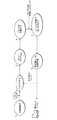
図2に示すように、先行技術のプリンタは、典型的には、6以上のユーザステップを必要とする。まず、ユーザがCADソフトウェアに3Dモデルを設計する。次いで、ユーザは、作製されるパーツの3Dモデルをスライスプログラムにアップロードする。ユーザが手作業で150〜250の設定を較正すると、スライスプログラムは3Dプリンタ10用の機械コードを生み出す。プロセスの第4のステップは、コンピュータまたはSDカード上のプログラムの形態の機械コードをプリントホストにアップロードすることである。そこから、機械コードがプリンタ10のマイクロプロセッサに流れて、作動が制御される。プリンタがプリントを実施すると、パーツが手動で取り外される。パーツの品質を検査した後で、パーツが再プリントを必要とするかどうかをユーザが判定する。 As shown in FIG. 2, prior art printers typically require six or more user steps. First, a user designs a 3D model in CAD software. The user then uploads a 3D model of the part to be created to the slice program. When the user manually calibrates the 150-250 setting, the slice program generates a machine code for the
全面的に自動の3Dプリンタシステムには、次のジョブを開始するためにパーツを取り外すのにその場にオペレータがいる必要を無くすように自動のパーツの取り外しが必要になる。現時点での自動パーツ取り外しシステムには3つの形態、コンベヤベルト、押し出し機ヘッドの取り付け具、およびプリントベッドの加熱/冷却がある。通常、こうしたシステムの欠点は、プリントプロセスおよび/または取り外しプロセスにとって好ましくない。概して、コンベヤベルトシステムはプラットフォームが可撓性でパーツが曲がるので成功していない。剛体のトラックを有するコンベヤベルトがやや高価な解決策を提示することがある。押し出し機ヘッドに取り外しのへらまたはブロックを取り付けることも知られている。このような機構は、典型的には、動力伝達系に過剰なストレスをかけ、プリントノズルの位置合わせが不良になって各層が水平とならないという問題が引き起こされる場合がある。最後に、加熱/冷却を用いてプリント面からパーツを解放することが知られている。このようなシステムではプリント中にプリント面が高温になる。パーツのプリントが終了すると、パッシブにプレートを冷却することができる。収縮するとパーツが「飛び出し」てしまう。 Fully automatic 3D printer systems require automatic part removal so that the operator does not have to be there to remove the part in order to start the next job. There are currently three forms of automatic part removal systems: conveyor belts, extruder head fittings, and print bed heating / cooling. Usually, the disadvantages of such systems are undesirable for the printing process and / or removal process. In general, conveyor belt systems are not successful because the platform is flexible and the parts bend. Conveyor belts with rigid tracks may present a rather expensive solution. It is also known to attach a removal spatula or block to the extruder head. Such a mechanism typically causes excessive stress on the power transmission system, which may cause problems such as poor print nozzle alignment and uneven layers. Finally, it is known to release parts from the print surface using heating / cooling. In such a system, the printing surface becomes hot during printing. When the parts are printed, the plate can be passively cooled. When it contracts, the parts “jump out”.
一態様では、本発明による3次元プリントシステムは、面上にパーツが作製されるプリント面を含む。プリントデバイスが、プリント面上にパーツをプリントするためにプリント面に対して制御運動するように支持されている。ブレードが、プリント面からパーツを解放するようにプリント面全体にわたって移動するように支持されている。本発明のこの態様の好ましい実施形態では、電磁制御の空気圧ピストンを用いてブレードを移動させる。ブレードは、プリント面の片側側方の支持体から片持ちにされてよい。あるいは、ブレードはプリント面の両側側方において支持されてよい。片持ちにされたブレードの場合は、支持体が順応性の接続箇所を成すことが好ましい。ブレードがパーツと係合する焼き入れ鋼部分を有することも好ましい。 In one aspect, a three-dimensional printing system according to the present invention includes a printed surface on which parts are made on the surface. A printing device is supported for controlled movement relative to the print surface to print the part on the print surface. A blade is supported for movement across the print surface to release the part from the print surface. In a preferred embodiment of this aspect of the invention, an electromagnetically controlled pneumatic piston is used to move the blade. The blade may be cantilevered from a support on one side of the printing surface. Alternatively, the blade may be supported on both sides of the print surface. In the case of a cantilevered blade, it is preferred that the support forms a compliant connection. It is also preferred that the blade has a hardened steel portion that engages the part.
好ましい実施形態では、ブレードを移動させるのにリードねじを設けることができる。あるいは、ベルトを駆動する駆動プーリを用いてブレードを移動させることができる。ラックアンドピニオン式の機構を用いてブレードを移動させることもできる。一実施形態では、ブレードはパーツの取り外しを容易にするために振動する。 In a preferred embodiment, a lead screw can be provided to move the blade. Alternatively, the blade can be moved using a drive pulley that drives the belt. The blade can also be moved using a rack and pinion type mechanism. In one embodiment, the blade vibrates to facilitate part removal.
別の態様では、本明細書に開示する3Dプリントシステムは、パーツがその上にプリントされるプリント面を含み、そのプリント面は配列された孔を含む。プリントデバイスが、プリント面上にパーツをプリントするためにプリント面に対して制御運動するように支持されている。ピンが、配列された孔に合うような配列に配置され、その面からパーツを持ち上げるように孔を通してピンを押し込む手段が設けられる。一実施形態では、孔を通してピンを押し込む手段は、プリント面をピンの位置まで下げることを含む。あるいは、ピンを引き上げることによって孔を通してピンを押し込む手段を設けることができる。 In another aspect, the 3D printing system disclosed herein includes a print surface on which a part is printed, and the print surface includes an array of holes. A printing device is supported for controlled movement relative to the print surface to print the part on the print surface. The pins are arranged in an arrangement to fit the arranged holes and means are provided for pushing the pins through the holes to lift the part from its surface. In one embodiment, the means for pushing the pin through the hole includes lowering the print surface to the position of the pin. Alternatively, means for pushing the pin through the hole by pulling the pin up can be provided.
さらに別の態様では、本発明は、パーツ位置の下に少なくとも1つの孔を含むプリント面を含む3次元プリントシステムである。圧縮空気が、面からパーツを持ち上げるために孔を通して導入される。 In yet another aspect, the present invention is a three-dimensional printing system that includes a printing surface that includes at least one hole under a part location. Compressed air is introduced through the holes to lift the part from the surface.
本発明のさらに別の態様では、システムはプリント面を振動させる手段を含む。プリント面を振動させるために電磁石を使用することができる。 In yet another aspect of the invention, the system includes means for vibrating the print surface. An electromagnet can be used to vibrate the printed surface.
本明細書に開示する実施形態の多くはさらに、解放されたパーツを取り外す補助デバイスを含む。補助装置は、解放されたパーツおよびブレードに取り付けられた回動式の障壁を拘束する圧縮空気ジェットの固定バリアを含む。 Many of the embodiments disclosed herein further include an auxiliary device that removes the released part. The auxiliary device includes a fixed barrier for the compressed air jet that constrains the released part and a pivoting barrier attached to the blade.
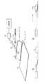
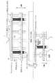
図3を参照すると、本発明の実施形態がパーツ取り外しブレード20を含み、そのパーツ取り外しブレード20はプリント済みのパーツ22を解放するように移動することができる。パーツがプリントされている間およびその後にそのパーツを評価するカメラ24が設けられている。本発明はまた、Wi−Fiネットワークに接続されたオンボードのプリンタホスト26も含む。先行技術のシステムと同じく、3Dモデルを修正およびスライスするソフトウェアが、プリンタに有線でつなげられたコンピュータとは対照的にクラウドに格納されている。プリンタがプリントする次のパーツを指示する自動の待ち行列が設けられている。 Referring to FIG. 3, an embodiment of the present invention includes a
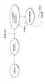
図4を参照すると、本明細書に開示するシステムは、先行技術の3Dプリンタに関して上記で論じた6つのステップとは対照的に、ユーザステップを3つしか必要としない。本システムでは、対象物制作後に3Dモデルがそのシステムにアップロードされる。管理者の承認(任意選択)の後に、パーツは自動的に修正およびスライスされ(3Dモデルから機械コードが作られ)、スライス設定が(速度対品質および速度対強度に関する2つのユーザインプットに基づいて)クラウド内で自動的に選択され、次いで、特定のプリンタのための自動の待ち行列に自動的にロードされる。プリンタが待ち行列のそのパーツに達すると、gコード(機械コード)が(典型的にはローカルのマイクロコンピュータの)プリンタのローカルホストプログラムに自動的にロードされ、プリンタのマイクロプロセッサに流れる。プリントプロセスが進むと、そのパーツが確実に正確にプリントするように自動のコンピュータ画像を用いてカメラ24が2D層をそれぞれモニタリングする。パーツはいずれかの層で不合格になると、自動的に取り外され再度プリントされる(人工知能ソフトウェアが必要だと判断する場合は、異なる設定での再スライスが再プリント前に行われる)。完成したパーツ(コンピュータ画像のサブシステムにより品質が再検査される)は、取り外されピックアップのために用意される。次いで、プリンタは待ち行列の次のパーツに進む。合わせると、厳密に3つのユーザステップ、対象物制作、3Dモデルのアップロード、および完成したパーツのピックアップがある。 Referring to FIG. 4, the system disclosed herein requires only three user steps as opposed to the six steps discussed above with respect to prior art 3D printers. In this system, the 3D model is uploaded to the system after the object is created. After administrator approval (optional), the part is automatically modified and sliced (machine code is made from the 3D model) and the slice settings are based on two user inputs (speed vs. quality and speed vs. strength) ) Automatically selected in the cloud and then automatically loaded into an automatic queue for a particular printer. When the printer reaches that part of the queue, the g code (machine code) is automatically loaded into the printer's local host program (typically in the local microcomputer) and flows to the printer's microprocessor. As the printing process proceeds, the
図5を参照すると、パーツ取り外しシステムの実施形態が示されている。電磁弁24によって制御された圧縮空気の原動力によりプレートを移動させるように、空気圧ピストン22を用いてプリントプレート12全体にわたって移動するブレード20が配置されている。ブレード20を移動させる原動力はパーツに損傷を与えることなくパーツを取り外すように調節されることが理解されよう。 Referring to FIG. 5, an embodiment of a parts removal system is shown. A
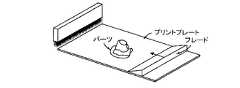
本明細書に開示するパーツ取り外しシステムの別の実施形態を図6に示す。この実施形態では、配列された孔がプリントベッドまたはプリント面12を貫通するように作製されている。プリント面12の下に付き出しピン30が複数配置されている。パーツがプリントされると、プリント面12がピン30の位置まで下がるか、またはピン30が持ち上げられてその配列の孔を貫通して、図示のようにプリント済みのパーツを持ち上げる。 Another embodiment of the part removal system disclosed herein is shown in FIG. In this embodiment, the arrayed holes are made to penetrate the print bed or
本発明のさらに別の実施形態を図7に示す。この実施形態では、プリント面12に孔があり、その孔を通してプリント済みのパーツの下から空気が噴射される。図7の下の部分に示すように空気圧によりプリント済みのパーツが持ち上げられる。 Yet another embodiment of the present invention is shown in FIG. In this embodiment, there is a hole in the
図8に本発明のさらに別の実施形態を示す。この実施形態では、ブレード20は、ユニットの片側にある順応性(コンプライアンス)のある接続箇所34の位置で片持ちにされている。ブレード20は、プリント面に合わせて平らにされており、パーツを解放するようにプリント面全体にわたって移動する。図9に示すように、パーツを持ち上げる能力をもたらすように、ブレード20が、焼き入れ鋼シート36がそれに取り付けられたアルミニウムなどの基板を有することが好ましい。 FIG. 8 shows still another embodiment of the present invention. In this embodiment, the
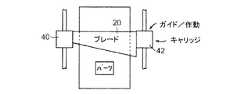
図10に、ねじ切りロッドまたはリードねじ38によりブレード20がプリント面12を横断してプリント済みのパーツに係合し、次いでそれを取り外す実施形態を示す。図11に示すように、ガイド40および42によって両側でブレード20を支持できることが企図される。 FIG. 10 illustrates an embodiment in which the threaded rod or
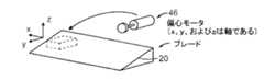
本発明のさらに別の実施形態を図12に示す。図12では、プリントプレート12上にプリントされたパーツを解放するように選択された手法で、電磁石44によりプリントプレート12を振動させる。さらに別の実施形態では、図13に示すように、ブレード20自体が振動する。ブレード20を振動させるために、重量が偏心したモータ46を設けることができる。 Yet another embodiment of the present invention is shown in FIG. In FIG. 12, the
図14に示すように、上記で論じたようにパーツを解放した後で、圧縮空気を用いてプリント面12からパーツを取り外すことができる。 As shown in FIG. 14, after releasing the part as discussed above, the part can be removed from the
図15に、パーツの移動を妨げる固定ブラシ48を示す。図16および図17に、すでに面から解放されたパーツを取り外すための機構の別の実施形態を示す。図18は、固定バリアを示す斜視図である。図19に回動動作する障壁を示す。 FIG. 15 shows a fixed
図20は、一実施形態のプリント面12の下面の断面図である。溝40は、プレート12が支持構造に対して平らにされるようにプリンタの支持体から延びる突起と噛み合うように適合されている。その機構は当業者には周知のとおり運動学的な連結部を成す。図20に示す溝40の機構により、選択した回転方向にプレート12を位置決めできるようになる。例えば磁石またはばねによってプレート12が定位置に予荷重をかけられて、連結された位置にプレート12を固定することが好ましい。 FIG. 20 is a cross-sectional view of the lower surface of the
本発明は、先行技術に関連して上記で論じたプリントおよび取り外しの欠点を解決する、自動のパーツの取り外しの解決策を提供するものである。本発明は、はるかにコストが低い、自動のパーツの取り外しを提供する構造および方法を開示する。 The present invention provides an automatic part removal solution that overcomes the printing and removal drawbacks discussed above in relation to the prior art. The present invention discloses a structure and method that provides automatic parts removal that is much less costly.
本発明の変形および変更が当業者には明らかであることが認められ、そのような変形および変更はいずれも添付の請求項の範囲内に包含されるものである。 It will be appreciated that variations and modifications of this invention will be apparent to those skilled in the art, and all such variations and modifications are intended to be included within the scope of the appended claims.
<付記>
[1]
面上にパーツが作製されるプリント面と、
前記プリント面上に前記パーツをプリントするために前記プリント面に対して制御運動するように支持されたプリントデバイスと、
前記プリント面から前記パーツを解放するように前記プリント面全体にわたって移動するように支持されたブレードと、
を備えることを特徴とする、3次元プリントシステム。
[2]
上記[1]に記載のプリントシステムであって、前記ブレードを移動させるために電磁制御の空気圧ピストンをさらに含むことを特徴とするプリントシステム。
[3]
上記[1]に記載のプリントシステムであって、前記ブレードが前記プリント面の片側の側方にある支持体から片持ちにされていることを特徴とするプリントシステム。
[4]
上記[1]に記載のプリントシステムであって、前記ブレードが前記プリント面の両側の側方において支持されることを特徴とするプリントシステム。
[5]
上記[3]に記載のプリントシステムであって、前記支持体が順応性の接続箇所を成すことを特徴とするプリントシステム。
[6]
上記[1]に記載のプリントシステムであって、前記ブレードが、前記パーツに係合する焼き入れ鋼部分を有することを特徴とするプリントシステム。
[7]
上記[1]に記載のプリントシステムであって、前記ブレードを移動させるリードねじをさらに含むことを特徴とするプリントシステム。
[8]
上記[1]に記載のプリントシステムであって、前記プリント済みのパーツを取り外すために前記ブレードを移動させるようにベルトを駆動する駆動プーリをさらに含むことを特徴とするプリントシステム。
[9]
上記[1]に記載のプリントシステムであって、前記ブレードを移動させるラックアンドピニオン式の機構をさらに含むことを特徴とするプリントシステム。
[10]
上記[1]に記載のプリントシステムであって、前記ブレードを振動させる手段をさらに含むことを特徴とするプリントシステム。
[11]
面上にパーツがプリントされるプリント面であって、配列された孔を含むプリント面と、
前記プリント面上に前記パーツをプリントするために前記プリント面に対して制御運動するように支持されたプリントデバイスと、
前記配列された孔に合うような配列に配置されたピンと、
前記面から前記パーツを持ち上げるように前記孔を通して前記ピンを押し込む手段と、
を備えることを特徴とする3次元プリントシステム。
[12]
上記[11]に記載のプリントシステムであって、前記孔を通して前記ピンを押し込む前記手段が前記ピンの上に前記プリント面を下げることを含むことを特徴とするプリントシステム。
[13]
上記[11]に記載のプリントシステムであって、前記孔を通して前記ピンを押し込む前記手段が前記ピンを引き上げることを含むことを特徴とするプリントシステム。
[14]
面上にパーツが作製されるプリント面であって、前記パーツ位置の下に少なくとも1つの孔を含むプリント面と、
前記プリント面上に前記パーツをプリントするために前記プリント面に対して制御運動するように支持されたプリントデバイスと、
前記孔を通して空気を導入して前記面から前記パーツを持ち上げる圧縮空気手段と、
を備えることを特徴とする3次元プリントシステム。
[15]
面上にパーツが作製されるプリント面と、
前記プリント面上に前記パーツをプリントするために前記プリント面に対して制御運動するように支持されたプリントデバイスと、
前記プリント面を振動させて前記パーツを解放する手段と、
を備えることを特徴とする3次元プリントシステム
[16]
上記[15]に記載のプリントシステムであって、電磁石が前記プリント面を振動させることを特徴とするプリントシステム。
[17]
上記[1]、[11]、[14]および[15]のいずれか1項に記載のプリントシステムであって、前記解放されたパーツを取り外すために補助デバイスをさらに含むことを特徴とするプリントシステム。
[18]
上記[17]に記載のプリントシステムであって、前記解放されたパーツを取り外すために圧縮空気ジェットをさらに含むことを特徴とするプリントシステム。
[19]
上記[1]、[11]、[14]および[15]のいずれか1項に記載のプリントシステムであって、解放されたパーツを拘束するために固定バリアをさらに含むことを特徴とするプリントシステム。
[20]
上記[1]、[11]、[14]および[15]のいずれか1項に記載のプリントシステムであって、前記ブレードに取り付けられトルクを生じるように回動する障壁をさらに含むことを特徴とするプリントシステム。
[21]
上記[1]、[11]、[14]および[15]のいずれか1項に記載のプリントシステムであって、解放されたパーツを取り外すために前記ブレードに装着された弾性バンドをさらに含むことを特徴とするプリントシステム。
[22]
上記[1]に記載のプリントシステムであって、首尾よくパーツの取り外しがなされたかを検出するカメラを少なくとも1つ含むコンピュータ画像システムをさらに含むことを特徴とするプリントシステム。
[23]
上記[1]に記載のプリントシステムであって、前記プリント面の迅速かつ正確平らにするために前記プリント面が支持構造に運動学的に連結されていることを特徴とするプリントシステム。
[24]
上記[23]に記載のプリントシステムであって、前記支持構造に対して前記プリント面に予荷重をかける構造をさらに含むことを特徴とするプリントシステム。
[25]
上記[24]に記載のプリントシステムであって、前記予荷重をかける構造が磁石を含むことを特徴とするプリントシステム。
[26]
上記[23]に記載のプリントシステムであって、前記支持構造が、選択した回転方向に前記プリント面がほぼ平らにされた位置にあることが可能になるように、前記支持構造から延びる突起を複数含むことを特徴とするプリントシステム。
<Appendix>
[1]
A printed surface on which parts are made, and
A printing device supported for controlled movement relative to the print surface to print the part on the print surface;
A blade supported to move across the print surface to release the part from the print surface;
A three-dimensional printing system comprising:
[2]
The printing system according to the above [1], further comprising an electromagnetically controlled pneumatic piston for moving the blade.
[3]
The printing system according to the above [1], wherein the blade is cantilevered from a support on one side of the printing surface.
[4]
The printing system according to [1], wherein the blade is supported on both sides of the printing surface.
[5]
The printing system according to the above [3], wherein the support forms an adaptable connection point.
[6]
The printing system according to [1], wherein the blade has a hardened steel portion that engages with the part.
[7]
The printing system according to [1], further including a lead screw that moves the blade.
[8]
The printing system according to [1], further comprising a drive pulley that drives a belt to move the blade to remove the printed part.
[9]
The printing system according to [1], further including a rack and pinion type mechanism for moving the blade.
[10]
The printing system according to the above [1], further comprising means for vibrating the blade.
[11]
A printed surface on which the parts are printed, the printed surface including the arranged holes;
A printing device supported for controlled movement relative to the print surface to print the part on the print surface;
Pins arranged in an arrangement to fit the arranged holes;
Means for pushing the pin through the hole to lift the part from the surface;
A three-dimensional printing system comprising:
[12]
The printing system according to [11], wherein the means for pushing the pin through the hole includes lowering the printing surface on the pin.
[13]
The printing system according to [11], wherein the means for pushing the pin through the hole includes lifting the pin.
[14]
A printed surface on which a part is produced, the printed surface comprising at least one hole below the part position;
A printing device supported for controlled movement relative to the print surface to print the part on the print surface;
Compressed air means for introducing air through the holes to lift the part from the surface;
A three-dimensional printing system comprising:
[15]
A printed surface on which parts are made, and
A printing device supported for controlled movement relative to the print surface to print the part on the print surface;
Means for vibrating the print surface to release the parts;
3D printing system [16] characterized by comprising
The print system according to [15], wherein an electromagnet vibrates the print surface.
[17]
The printing system according to any one of [1], [11], [14], and [15] above, further including an auxiliary device for removing the released part. system.
[18]
The printing system according to [17], further comprising a compressed air jet for removing the released part.
[19]
The printing system according to any one of [1], [11], [14], and [15] above, further including a fixed barrier for restraining the released part. system.
[20]
The printing system according to any one of [1], [11], [14], and [15], further including a barrier that is attached to the blade and rotates to generate torque. And a printing system.
[21]
The printing system according to any one of [1], [11], [14], and [15], further including an elastic band attached to the blade to remove the released part. A printing system characterized by
[22]
The printing system according to the above [1], further comprising a computer image system including at least one camera for detecting whether parts have been successfully removed.
[23]
The printing system according to [1], wherein the printing surface is kinematically connected to a support structure to quickly and accurately flatten the printing surface.
[24]
The printing system according to [23], further including a structure for applying a preload to the print surface with respect to the support structure.
[25]
The printing system according to [24], wherein the structure to which the preload is applied includes a magnet.
[26]
The printing system according to [23], wherein the support structure has a protrusion extending from the support structure so as to allow the support surface to be in a position where the print surface is substantially flattened in a selected rotation direction. A printing system comprising a plurality of printing systems.
Claims (14)
Translated fromJapanese前記プリント面上に前記パーツをプリントするために前記プリント面に対して制御運動するように支持されたプリントデバイスと、
前記配列された孔に合うような配列に配置されたピンと、
前記面から前記パーツを持ち上げるように前記孔を通して前記ピンを押し込む手段と、
を備えることを特徴とする3次元プリントシステム。A printed surface on which the parts are printed, the printed surface including the arranged holes;
A printing device supported for controlled movement relative to the print surface to print the part on the print surface;
Pins arranged in an arrangement to fit the arranged holes;
Means for pushing the pin through the hole to lift the part from the surface;
A three-dimensional printing system comprising:
前記プリント面上に前記パーツをプリントするために前記プリント面に対して制御運動するように支持されたプリントデバイスと、
前記孔を通して空気を導入して前記面から前記パーツを持ち上げる圧縮空気手段と、
を備えることを特徴とする3次元プリントシステム。A printed surface on which a part is produced, the printed surface comprising at least one hole below the part position;
A printing device supported for controlled movement relative to the print surface to print the part on the print surface;
Compressed air means for introducing air through the holes to lift the part from the surface;
A three-dimensional printing system comprising:
前記プリント面上に前記パーツをプリントするために前記プリント面に対して制御運動するように支持されたプリントデバイスと、
前記プリント面を振動させて前記パーツを解放する手段と、
を備えることを特徴とする3次元プリントシステムA printed surface on which parts are made, and
A printing device supported for controlled movement relative to the print surface to print the part on the print surface;
Means for vibrating the print surface to release the parts;
A three-dimensional printing system comprising:
Applications Claiming Priority (4)
| Application Number | Priority Date | Filing Date | Title |
|---|---|---|---|
| US201361759686P | 2013-02-01 | 2013-02-01 | |
| US61/759,686 | 2013-02-01 | ||
| US14/157,027US9289946B2 (en) | 2013-02-01 | 2014-01-16 | Automated three-dimensional printer part removal |
| US14/157,027 | 2014-01-16 |
Related Parent Applications (1)
| Application Number | Title | Priority Date | Filing Date |
|---|---|---|---|
| JP2015556158ADivisionJP6215964B2 (en) | 2013-02-01 | 2014-01-31 | Automatic part removal of 3D printer |
Related Child Applications (1)
| Application Number | Title | Priority Date | Filing Date |
|---|---|---|---|
| JP2019020275ADivisionJP2019073032A (en) | 2013-02-01 | 2019-02-07 | Three-dimensional printing system |
Publications (2)
| Publication Number | Publication Date |
|---|---|
| JP2017177819Atrue JP2017177819A (en) | 2017-10-05 |
| JP6480509B2 JP6480509B2 (en) | 2019-03-13 |
Family
ID=51259407
Family Applications (3)
| Application Number | Title | Priority Date | Filing Date |
|---|---|---|---|
| JP2015556158AActiveJP6215964B2 (en) | 2013-02-01 | 2014-01-31 | Automatic part removal of 3D printer |
| JP2017115848AActiveJP6480509B2 (en) | 2013-02-01 | 2017-06-13 | Automatic part removal of 3D printer |
| JP2019020275APendingJP2019073032A (en) | 2013-02-01 | 2019-02-07 | Three-dimensional printing system |
Family Applications Before (1)
| Application Number | Title | Priority Date | Filing Date |
|---|---|---|---|
| JP2015556158AActiveJP6215964B2 (en) | 2013-02-01 | 2014-01-31 | Automatic part removal of 3D printer |
Family Applications After (1)
| Application Number | Title | Priority Date | Filing Date |
|---|---|---|---|
| JP2019020275APendingJP2019073032A (en) | 2013-02-01 | 2019-02-07 | Three-dimensional printing system |
Country Status (9)
| Country | Link |
|---|---|
| US (2) | US9289946B2 (en) |
| EP (2) | EP2951004B1 (en) |
| JP (3) | JP6215964B2 (en) |
| CN (2) | CN108891028A (en) |
| AU (1) | AU2014212279B2 (en) |
| CA (2) | CA2899590C (en) |
| ES (1) | ES2704676T3 (en) |
| MX (1) | MX361232B (en) |
| WO (1) | WO2014121032A1 (en) |
Cited By (2)
| Publication number | Priority date | Publication date | Assignee | Title |
|---|---|---|---|---|
| CN109228309A (en)* | 2018-09-27 | 2019-01-18 | 保靖锐恩电子有限责任公司 | A kind of shaped platform for 3D printer |
| WO2023067707A1 (en)* | 2021-10-19 | 2023-04-27 | 株式会社Fuji | 3d forming apparatus and pallet transfer method |
Families Citing this family (86)
| Publication number | Priority date | Publication date | Assignee | Title |
|---|---|---|---|---|
| TWI548539B (en)* | 2013-12-12 | 2016-09-11 | 三緯國際立體列印科技股份有限公司 | Three dimensional printing apparatus |
| US10987845B2 (en)* | 2014-02-11 | 2021-04-27 | Structur3D Printing Incorporated | Multi-material extruder and extrusion method for three-dimensional (3D) printing |
| US9486878B2 (en) | 2014-06-20 | 2016-11-08 | Velo3D, Inc. | Apparatuses, systems and methods for three-dimensional printing |
| US10668709B2 (en)* | 2014-08-12 | 2020-06-02 | Carbon, Inc. | Three-dimensional printing using carriers with release mechanisms |
| US9821518B2 (en) | 2014-08-19 | 2017-11-21 | Daniel A. Bloom | Precision platform assembly for three-dimensional printer |
| US20170259507A1 (en)* | 2014-12-01 | 2017-09-14 | Sabic Global Technologies B.V. | Additive manufacturing process automation systems and methods |
| US9884449B2 (en)* | 2015-04-02 | 2018-02-06 | Xerox Corporation | Three-dimensional printed part removal using an interlaced platen |
| US9381701B1 (en) | 2015-04-02 | 2016-07-05 | Xerox Corporation | Printer and method for releasing three-dimensionally printed parts from a platen using actuators |
| US10906244B2 (en)* | 2015-04-02 | 2021-02-02 | Xerox Corporation | Ultrasonic removal methods of three-dimensionally printed parts |
| US9782964B2 (en)* | 2015-04-02 | 2017-10-10 | Xerox Corporation | System and method for removing three-dimensional printed parts from a platen using inductive heating and gravity |
| US9937669B2 (en) | 2015-04-02 | 2018-04-10 | Xerox Corporation | Three-dimensional printed part removal using a bimetallic platen |
| US10814551B2 (en)* | 2015-04-02 | 2020-10-27 | Xerox Corporation | Three-dimensional printed part removal using an elastomer sheet |
| US20180169942A1 (en)* | 2015-05-19 | 2018-06-21 | Addifab Aps | Apparatus and method for release of additively manufactured products and build platform |
| WO2017018938A1 (en)* | 2015-07-27 | 2017-02-02 | Agency For Science, Technology And Research | A multi-modal printing system and method of operating the same |
| US9916177B2 (en)* | 2015-08-19 | 2018-03-13 | International Business Machines Corporation | Predictive workload scheduling with integrated analytics |
| EP4049772A1 (en) | 2015-10-30 | 2022-08-31 | Seurat Technologies, Inc. | Chamber systems for additive manufacturing |
| US10065270B2 (en) | 2015-11-06 | 2018-09-04 | Velo3D, Inc. | Three-dimensional printing in real time |
| CN106738856A (en)* | 2015-11-17 | 2017-05-31 | 亚德利塑胶工厂股份有限公司 | 3D print job platform material returned mechanism |
| US10286603B2 (en) | 2015-12-10 | 2019-05-14 | Velo3D, Inc. | Skillful three-dimensional printing |
| WO2017100817A1 (en)* | 2015-12-18 | 2017-06-22 | Aurora Labs Limited | 3d printing method and apparatus |
| US20170239719A1 (en) | 2016-02-18 | 2017-08-24 | Velo3D, Inc. | Accurate three-dimensional printing |
| FR3052380B1 (en)* | 2016-06-14 | 2018-11-02 | Universite De Limoges | PROCESS AND MACHINE FOR THE PRODUCTION OF WORKPIECES BY THE TECHNIQUE OF PASSIVE ADDITIVE PROCESSES |
| US11691343B2 (en) | 2016-06-29 | 2023-07-04 | Velo3D, Inc. | Three-dimensional printing and three-dimensional printers |
| EP3492244A1 (en) | 2016-06-29 | 2019-06-05 | VELO3D, Inc. | Three-dimensional printing system and method for three-dimensional printing |
| JP6809858B2 (en)* | 2016-09-30 | 2021-01-06 | 株式会社Screenホールディングス | Three-dimensional modeling method |
| US20180093418A1 (en) | 2016-09-30 | 2018-04-05 | Velo3D, Inc. | Three-dimensional objects and their formation |
| CA3039851A1 (en) | 2016-10-21 | 2018-04-26 | Mosaic Manufacturing Ltd. | Joiners, methods of joining, and related systems for additive manufacturing |
| US10723075B2 (en) | 2016-11-02 | 2020-07-28 | R3 Printing, Inc. | System and method for automated successive three-dimensional printing |
| US11660819B2 (en) | 2016-11-02 | 2023-05-30 | R3 Printing, Inc. | System and method for automated successive three-dimensional printing |
| US20180126460A1 (en) | 2016-11-07 | 2018-05-10 | Velo3D, Inc. | Gas flow in three-dimensional printing |
| CN108215173B (en)* | 2016-12-15 | 2025-04-04 | 上海普利生三维科技有限公司 | Light-curing three-dimensional printing device, method and system capable of automatic and continuous printing |
| CN108215172B (en)* | 2016-12-15 | 2022-02-15 | 上海普利生机电科技有限公司 | a three-dimensional printer |
| US10456984B2 (en)* | 2016-12-16 | 2019-10-29 | Massachusetts Institute Of Technology | Adaptive material deposition for additive manufacturing |
| US20180186082A1 (en)* | 2017-01-05 | 2018-07-05 | Velo3D, Inc. | Optics in three-dimensional printing |
| US11472105B2 (en)* | 2017-01-09 | 2022-10-18 | International Business Machines Corporation | Methods and systems for 3D printing with modifiable support |
| US10315252B2 (en) | 2017-03-02 | 2019-06-11 | Velo3D, Inc. | Three-dimensional printing of three-dimensional objects |
| CN106863804A (en)* | 2017-03-09 | 2017-06-20 | 福建省速卖通电子商务有限公司 | A kind of 3D printing supporting station with anti-sticking function |
| US10449696B2 (en) | 2017-03-28 | 2019-10-22 | Velo3D, Inc. | Material manipulation in three-dimensional printing |
| US10974474B2 (en)* | 2017-06-12 | 2021-04-13 | General Electric Company | Applicator repair for additive manufacturing system |
| CN107175828A (en)* | 2017-07-21 | 2017-09-19 | 芜湖智享三维打印服务有限公司 | A kind of 3D printer that function is quickly removed with finished product |
| US10933587B2 (en)* | 2017-10-06 | 2021-03-02 | International Business Machines Corporation | Removing a printed item from a printer |
| DE102017124177A1 (en)* | 2017-10-17 | 2019-04-18 | Trumpf Laser- Und Systemtechnik Gmbh | Tool change in generative production |
| CN107901407B (en)* | 2017-11-27 | 2021-12-07 | 庄小霞 | Three-dimensional printer and printing method thereof |
| US10272525B1 (en) | 2017-12-27 | 2019-04-30 | Velo3D, Inc. | Three-dimensional printing systems and methods of their use |
| US10201503B1 (en) | 2018-01-09 | 2019-02-12 | Triastek, Inc. | Precision pharmaceutical 3D printing device |
| EP3810401B1 (en)* | 2018-06-22 | 2022-08-03 | 3D Systems, Inc. | Method of verifying integrity of a post-process removal of support material |
| EP3608084A1 (en)* | 2018-08-08 | 2020-02-12 | Concept Laser GmbH | Separating device |
| US20200061871A1 (en)* | 2018-08-21 | 2020-02-27 | Cincinnati Incorporated | Systems and apparatus for additive manufacturing |
| ES2760148A1 (en)* | 2018-11-12 | 2020-05-13 | Triditive S L | AUTOMATED MACHINE AND ADDITIVE MANUFACTURING SYSTEM (Machine-translation by Google Translate, not legally binding) |
| CN109501246B (en)* | 2018-12-26 | 2020-12-08 | 林海 | 3D printing apparatus is used in casting |
| CN113543959A (en)* | 2019-02-14 | 2021-10-22 | 瑞派德夏博有限公司 | Apparatus for producing three-dimensional objects |
| CA3136003A1 (en)* | 2019-04-04 | 2020-10-08 | Pektech Holdings Inc. | Automated part removal for additive manufacturing |
| JP7314598B2 (en)* | 2019-04-22 | 2023-07-26 | セイコーエプソン株式会社 | Three-dimensional modeling apparatus and method for manufacturing three-dimensional model |
| US12059841B2 (en) | 2019-05-23 | 2024-08-13 | General Electric Company | Additive manufacturing recoat assemblies including sensors and methods for using the same |
| WO2020237142A1 (en)* | 2019-05-23 | 2020-11-26 | General Electric Company | Additive manufacturing recoat assemblies including a vacuum and methods for using the same |
| US12076918B2 (en) | 2019-05-23 | 2024-09-03 | General Electric Company | Additive manufacturing apparatuses and methods for using the same |
| US12172370B2 (en) | 2019-05-23 | 2024-12-24 | General Electric Company | Recoat assemblies for additive manufacturing systems and methods for using the same |
| EP3972847A1 (en) | 2019-05-23 | 2022-03-30 | General Electric Company | Printing assemblies and methods for using the same |
| EP3972757A1 (en) | 2019-05-23 | 2022-03-30 | General Electric Company | Additive manufacturing apparatuses and methods |
| EP3972760A1 (en) | 2019-05-23 | 2022-03-30 | General Electric Company | Fluid management and circulation systems for use in additive manufacturing apparatuses |
| EP3972761A2 (en) | 2019-05-23 | 2022-03-30 | General Electric Company | Cleaning fluids for use in additive manufacturing apparatuses and methods for monitoring status and performance of the same |
| US12208583B2 (en) | 2019-05-23 | 2025-01-28 | General Electric Company | Wiper arrays for use in additive manufacturing apparatuses |
| CN114206591A (en) | 2019-05-23 | 2022-03-18 | 通用电气公司 | Cleaning system for additive manufacturing apparatus and method of using same |
| CA3148849A1 (en) | 2019-07-26 | 2021-02-04 | Velo3D, Inc. | Quality assurance in formation of three-dimensional objects |
| RU195094U1 (en)* | 2019-08-07 | 2020-01-15 | Федеральное государственное бюджетное образовательное учреждение высшего образования "Волгоградский государственный технический университет" (ВолгГТУ) | Device for automatically removing and removing printed products from a 3D printer camera |
| US12384112B2 (en) | 2019-08-20 | 2025-08-12 | Triastek, Inc. | High-throughput and high-precision pharmaceutical additive manufacturing system |
| US11269312B2 (en) | 2019-09-06 | 2022-03-08 | International Business Machines Corporation | Three dimensional printing vehicle-based auto-correction in a structure |
| AT523221B1 (en)* | 2019-11-15 | 2023-01-15 | Genera Printer Gmbh | processing device |
| JP7601419B2 (en)* | 2020-01-23 | 2024-12-17 | インポッシブル オブジェクツ、インコーポレイテッド | Camera-based monitoring system for 3D printing |
| CN115397652A (en)* | 2020-02-17 | 2022-11-25 | 南京三迭纪医药科技有限公司 | Continuous blanking and packaging system for medicine additive manufacturing |
| EP3892446A1 (en)* | 2020-04-08 | 2021-10-13 | DENTSPLY SIRONA Inc. | Building plate assembly for use in an additive manufacturing apparatus |
| WO2021221900A1 (en)* | 2020-04-30 | 2021-11-04 | Carbon, Inc. | Film remover apparatus for additive manufacturing build platforms and related methods |
| CN111633981B (en)* | 2020-05-27 | 2022-04-15 | 芜湖职业技术学院 | A high-efficiency powder-spreading 3D printer |
| CN118769539A (en) | 2020-07-10 | 2024-10-15 | 南京三迭纪医药科技有限公司 | High-precision additive manufacturing devices and high-throughput additive manufacturing systems |
| CN112276117A (en)* | 2020-10-12 | 2021-01-29 | 安徽哈特三维科技有限公司 | Metal powder removing device of alloy type 3D printer |
| US12162074B2 (en) | 2020-11-25 | 2024-12-10 | Lawrence Livermore National Security, Llc | System and method for large-area pulsed laser melting of metallic powder in a laser powder bed fusion application |
| CN112743847B (en)* | 2020-11-30 | 2023-08-29 | 安徽工程大学 | A spatula for separating printed models of a 3D printer |
| CN113561489A (en)* | 2021-07-29 | 2021-10-29 | 深圳市创想三帝科技有限公司 | Shedder and 3D printer |
| RU209858U1 (en)* | 2021-10-22 | 2022-03-23 | Общество с ограниченной ответственностью "СКАНИ" | 3D PRINTING TABLE DEVICE WITH AUTOMATIC PART REMOVAL CONVEYOR SYSTEM |
| US20230256676A1 (en)* | 2022-02-15 | 2023-08-17 | Peter Liquan Zhou | Apparatus and Method for Three-Dimensional Printing without Human Intervention |
| US11829671B2 (en)* | 2022-03-17 | 2023-11-28 | Xerox Corporation | Transfer of print queues via machine readable codes |
| IT202200024153A1 (en)* | 2022-11-24 | 2024-05-24 | Kentstrapper S R L | PRINT QUEUE MANAGEMENT AND AUTOMATIC PART REMOVAL SYSTEM FOR A 3D PRINTER |
| TWI844289B (en)* | 2023-03-03 | 2024-06-01 | 示昌智造有限公司 | Printing and cutting machine structure |
| CN117549560B (en)* | 2024-01-11 | 2024-04-02 | 西南石油大学 | A 3D printer stripping device |
| US12358221B1 (en) | 2024-03-25 | 2025-07-15 | King Saud University | Three-dimensional (3D) printer having a variously configurable printing platform assembly |
| CN118752771A (en)* | 2024-07-12 | 2024-10-11 | 江苏申久(集团)有限公司 | Composite fiber extrusion device |
Citations (3)
| Publication number | Priority date | Publication date | Assignee | Title |
|---|---|---|---|---|
| US20070126157A1 (en)* | 2005-12-02 | 2007-06-07 | Z Corporation | Apparatus and methods for removing printed articles from a 3-D printer |
| JP2010100884A (en)* | 2008-10-22 | 2010-05-06 | Panasonic Electric Works Co Ltd | Method for producing three-dimensionally shaped object |
| US20120072006A1 (en)* | 2010-09-17 | 2012-03-22 | Synerdyne Corporation | System and method for rapid fabrication of arbitrary three-dimensional objects |
Family Cites Families (43)
| Publication number | Priority date | Publication date | Assignee | Title |
|---|---|---|---|---|
| US4491559A (en)* | 1979-12-31 | 1985-01-01 | Kennametal Inc. | Flowable composition adapted for sintering and method of making |
| US4929073A (en)* | 1984-10-24 | 1990-05-29 | Hughes Aircraft Company | Kinematic mount |
| US5204055A (en)* | 1989-12-08 | 1993-04-20 | Massachusetts Institute Of Technology | Three-dimensional printing techniques |
| DE19511772C2 (en)* | 1995-03-30 | 1997-09-04 | Eos Electro Optical Syst | Device and method for producing a three-dimensional object |
| US6065898A (en)* | 1995-08-07 | 2000-05-23 | The Regents Of The University Of California | Three tooth kinematic coupling |
| US5678944A (en)* | 1995-12-07 | 1997-10-21 | Aesop, Inc. | Flexural mount kinematic couplings and method |
| US5730817A (en)* | 1996-04-22 | 1998-03-24 | Helisys, Inc. | Laminated object manufacturing system |
| US5748827A (en)* | 1996-10-23 | 1998-05-05 | University Of Washington | Two-stage kinematic mount |
| US20010014409A1 (en)* | 1997-04-04 | 2001-08-16 | Cohen Adam L. | Article, method, and apparatus for electrochemical fabrication |
| US6072569A (en)* | 1998-06-09 | 2000-06-06 | Eastman Kodak Company | Apparatus and a method for measurement of wedge in optical components |
| DE19937770C2 (en)* | 1999-08-10 | 2002-01-03 | Bayer Ag | Process for the production of three-dimensional or flat structures |
| US6325351B1 (en)* | 2000-01-05 | 2001-12-04 | The Regents Of The University Of California | Highly damped kinematic coupling for precision instruments |
| JP2001277367A (en)* | 2000-03-30 | 2001-10-09 | Sanyo Electric Co Ltd | Stereolithography device and stereolithography production method |
| JP2002178412A (en)* | 2000-12-14 | 2002-06-26 | Sanyo Electric Co Ltd | Stereolithography device and stereolithography production method |
| JP2002337242A (en)* | 2001-05-17 | 2002-11-27 | Kawakami Sangyo Co Ltd | Electric transmission system for product |
| US6729589B2 (en)* | 2002-10-07 | 2004-05-04 | Gizmonics, Inc. | Kinematic mount |
| KR100519051B1 (en)* | 2003-07-11 | 2005-10-06 | 한국과학기술원 | 3-dimensional shape-process apparatus using non-contact heating tool and method thereof |
| US7127309B2 (en)* | 2004-02-10 | 2006-10-24 | Stratasys, Inc. | Modeling apparatus with tray substrate |
| JP2005231333A (en)* | 2004-02-17 | 2005-09-02 | Chubu Nippon Kogyo Kk | Modeling base of stereolithography equipment by regulated liquid level method |
| US8119053B1 (en)* | 2004-03-18 | 2012-02-21 | 3D Systems, Inc. | Apparatus for three dimensional printing using imaged layers |
| US7790096B2 (en)* | 2005-03-31 | 2010-09-07 | 3D Systems, Inc. | Thermal management system for a removable build chamber for use with a laser sintering system |
| EP1759791A1 (en) | 2005-09-05 | 2007-03-07 | Nederlandse Organisatie voor toegepast- natuurwetenschappelijk onderzoek TNO | Apparatus and method for building a three-dimensional article |
| US7690909B2 (en)* | 2005-09-30 | 2010-04-06 | 3D Systems, Inc. | Rapid prototyping and manufacturing system and method |
| WO2009102200A1 (en)* | 2008-02-14 | 2009-08-20 | Nederlandse Organistie Voor Toegepast-Natuurwetenschappelijk Onderzoek Tno | Method and system for layerwise production of a tangible object |
| US8206637B2 (en)* | 2008-10-14 | 2012-06-26 | The Boeing Company | Geometry adaptive laser sintering system |
| US8153183B2 (en)* | 2008-10-21 | 2012-04-10 | Stratasys, Inc. | Adjustable platform assembly for digital manufacturing system |
| CN201470568U (en)* | 2009-08-25 | 2010-05-19 | 中国科学院上海应用物理研究所 | Automatic coating and scraping machine |
| US8282380B2 (en) | 2010-08-18 | 2012-10-09 | Makerbot Industries | Automated 3D build processes |
| JP2013067036A (en)* | 2011-09-21 | 2013-04-18 | Keyence Corp | Three-dimensional shaping apparatus |
| US9205690B2 (en)* | 2012-03-16 | 2015-12-08 | Stratasys, Inc. | Automated calibration method for additive manufacturing system, and method of use thereof |
| US9481134B2 (en)* | 2012-06-08 | 2016-11-01 | Makerbot Industries, Llc | Build platform leveling with tactile feedback |
| US20140085620A1 (en)* | 2012-09-24 | 2014-03-27 | Maxim Lobovsky | 3d printer with self-leveling platform |
| GB201322647D0 (en)* | 2013-12-20 | 2014-02-05 | Renishaw Plc | Additive manufacturing apparatus and method |
| NL2012198C2 (en)* | 2014-02-04 | 2015-08-06 | Leapfrog B V | DEVICE FOR FORMING A WORKPIECE THROUGH 3D EXTRUSION. |
| US20150276119A1 (en)* | 2014-03-28 | 2015-10-01 | Scott Booker | Three-dimensional printer platform leveling apparatus and method |
| US9895872B2 (en)* | 2014-07-31 | 2018-02-20 | Xyzprinting, Inc. | Three-dimensional printing apparatus |
| US9821518B2 (en)* | 2014-08-19 | 2017-11-21 | Daniel A. Bloom | Precision platform assembly for three-dimensional printer |
| WO2016032891A1 (en)* | 2014-08-28 | 2016-03-03 | Incodema3D, LLC | Additive manufacturing device |
| US9656424B2 (en)* | 2014-09-29 | 2017-05-23 | Xerox Corporation | System for adjusting platform height during three-dimensional printing of an object |
| US9724878B2 (en)* | 2014-10-20 | 2017-08-08 | Lenovo Enterprise Solutions (Singapore) Pte. Ltd. | Three-dimensional printer having an expandable envelope |
| KR101591938B1 (en)* | 2015-01-19 | 2016-02-04 | 숭실대학교산학협력단 | 3-d printer having dual stage |
| TWI555647B (en)* | 2015-08-10 | 2016-11-01 | 東友科技股份有限公司 | Supporting module of printing platform and three-dimensional printer using same |
| US10514678B2 (en)* | 2016-06-28 | 2019-12-24 | Robert Bosch Tool Corporation | Method for leveling a 3-D printing platform and a 3-D platform with adjustable level |
- 2014
- 2014-01-16USUS14/157,027patent/US9289946B2/enactiveActive
- 2014-01-31MXMX2015009971Apatent/MX361232B/enactiveIP Right Grant
- 2014-01-31AUAU2014212279Apatent/AU2014212279B2/enactiveActive
- 2014-01-31EPEP14707000.7Apatent/EP2951004B1/enactiveActive
- 2014-01-31ESES14707000Tpatent/ES2704676T3/enactiveActive
- 2014-01-31CNCN201810599439.9Apatent/CN108891028A/enactivePending
- 2014-01-31JPJP2015556158Apatent/JP6215964B2/enactiveActive
- 2014-01-31CACA2899590Apatent/CA2899590C/enactiveActive
- 2014-01-31CACA3014094Apatent/CA3014094A1/ennot_activeAbandoned
- 2014-01-31CNCN201480007068.0Apatent/CN105026131B/enactiveActive
- 2014-01-31WOPCT/US2014/014078patent/WO2014121032A1/enactiveApplication Filing
- 2014-01-31EPEP18172343.8Apatent/EP3392026A1/ennot_activeWithdrawn
- 2016
- 2016-02-11USUS15/041,208patent/US20160159010A1/ennot_activeAbandoned
- 2017
- 2017-06-13JPJP2017115848Apatent/JP6480509B2/enactiveActive
- 2019
- 2019-02-07JPJP2019020275Apatent/JP2019073032A/enactivePending
Patent Citations (3)
| Publication number | Priority date | Publication date | Assignee | Title |
|---|---|---|---|---|
| US20070126157A1 (en)* | 2005-12-02 | 2007-06-07 | Z Corporation | Apparatus and methods for removing printed articles from a 3-D printer |
| JP2010100884A (en)* | 2008-10-22 | 2010-05-06 | Panasonic Electric Works Co Ltd | Method for producing three-dimensionally shaped object |
| US20120072006A1 (en)* | 2010-09-17 | 2012-03-22 | Synerdyne Corporation | System and method for rapid fabrication of arbitrary three-dimensional objects |
Cited By (3)
| Publication number | Priority date | Publication date | Assignee | Title |
|---|---|---|---|---|
| CN109228309A (en)* | 2018-09-27 | 2019-01-18 | 保靖锐恩电子有限责任公司 | A kind of shaped platform for 3D printer |
| CN109228309B (en)* | 2018-09-27 | 2020-02-18 | 保靖锐恩电子有限责任公司 | A shaping platform for 3D printer |
| WO2023067707A1 (en)* | 2021-10-19 | 2023-04-27 | 株式会社Fuji | 3d forming apparatus and pallet transfer method |
Also Published As
| Publication number | Publication date |
|---|---|
| US9289946B2 (en) | 2016-03-22 |
| JP6480509B2 (en) | 2019-03-13 |
| CN108891028A (en) | 2018-11-27 |
| CN105026131A (en) | 2015-11-04 |
| CA2899590A1 (en) | 2014-08-07 |
| CA2899590C (en) | 2019-06-25 |
| JP2019073032A (en) | 2019-05-16 |
| EP2951004B1 (en) | 2018-11-28 |
| AU2014212279A1 (en) | 2015-08-20 |
| AU2014212279B2 (en) | 2017-02-16 |
| MX361232B (en) | 2018-11-30 |
| EP3392026A1 (en) | 2018-10-24 |
| WO2014121032A1 (en) | 2014-08-07 |
| JP6215964B2 (en) | 2017-10-18 |
| US20160159010A1 (en) | 2016-06-09 |
| EP2951004A1 (en) | 2015-12-09 |
| CN105026131B (en) | 2018-09-14 |
| US20140220168A1 (en) | 2014-08-07 |
| JP2016508904A (en) | 2016-03-24 |
| MX2015009971A (en) | 2015-09-29 |
| ES2704676T3 (en) | 2019-03-19 |
| CA3014094A1 (en) | 2014-08-07 |
Similar Documents
| Publication | Publication Date | Title |
|---|---|---|
| JP6480509B2 (en) | Automatic part removal of 3D printer | |
| CN109795113B (en) | 3D printer and three-dimensional model printing method | |
| JP2019073032A5 (en) | ||
| JP2024514971A (en) | Detachment control system and method for 3D printers | |
| CN109982851B (en) | screen printing machine | |
| KR100920802B1 (en) | Cotton Glove Printing Device | |
| JP2017109326A (en) | Device for producing molding and control method | |
| US20180022126A1 (en) | Print object holding tool, and inkjet printer having the print object holding tool | |
| CN105150534B (en) | Slidingtype 3D printing device and its Method of printing | |
| EP2712736A1 (en) | Method and system for modifying a surface topography | |
| JP2019025664A (en) | Three-dimensional molding apparatus | |
| CN107055139B (en) | Printing apparatus and method for moving medium support | |
| JP2017177456A5 (en) | ||
| JP7013307B2 (en) | Printers and printing systems with cutting heads | |
| JP3552522B2 (en) | Component bonding method and apparatus | |
| EP4370307B1 (en) | Pivoting building platform for creating a parallel building plane | |
| US20250187329A1 (en) | Recording device and control method of recording device | |
| JP2010125747A (en) | Inkjet printer | |
| WO2025154223A1 (en) | Printing control device and printing control method | |
| CN120461833A (en) | Finished product blanking device of 3D printer and application method | |
| JP2001287337A (en) | Screen printer | |
| JP2019104196A (en) | Transfer printer | |
| CN110681828A (en) | Automatic printing test paper conveying device and test paper conveying method | |
| JP2007090754A (en) | Printer |
Legal Events
| Date | Code | Title | Description |
|---|---|---|---|
| A621 | Written request for application examination | Free format text:JAPANESE INTERMEDIATE CODE: A621 Effective date:20170713 | |
| A131 | Notification of reasons for refusal | Free format text:JAPANESE INTERMEDIATE CODE: A131 Effective date:20180626 | |
| A601 | Written request for extension of time | Free format text:JAPANESE INTERMEDIATE CODE: A601 Effective date:20180919 | |
| A521 | Request for written amendment filed | Free format text:JAPANESE INTERMEDIATE CODE: A523 Effective date:20181122 | |
| TRDD | Decision of grant or rejection written | ||
| A01 | Written decision to grant a patent or to grant a registration (utility model) | Free format text:JAPANESE INTERMEDIATE CODE: A01 Effective date:20190108 | |
| A61 | First payment of annual fees (during grant procedure) | Free format text:JAPANESE INTERMEDIATE CODE: A61 Effective date:20190207 | |
| R150 | Certificate of patent or registration of utility model | Ref document number:6480509 Country of ref document:JP Free format text:JAPANESE INTERMEDIATE CODE: R150 | |
| R250 | Receipt of annual fees | Free format text:JAPANESE INTERMEDIATE CODE: R250 | |
| R250 | Receipt of annual fees | Free format text:JAPANESE INTERMEDIATE CODE: R250 | |
| R250 | Receipt of annual fees | Free format text:JAPANESE INTERMEDIATE CODE: R250 | |
| R250 | Receipt of annual fees | Free format text:JAPANESE INTERMEDIATE CODE: R250 |