JP2017176264A - Biological information measuring device and biological information measuring program - Google Patents
Biological information measuring device and biological information measuring programDownload PDFInfo
- Publication number
- JP2017176264A JP2017176264AJP2016064455AJP2016064455AJP2017176264AJP 2017176264 AJP2017176264 AJP 2017176264AJP 2016064455 AJP2016064455 AJP 2016064455AJP 2016064455 AJP2016064455 AJP 2016064455AJP 2017176264 AJP2017176264 AJP 2017176264A
- Authority
- JP
- Japan
- Prior art keywords
- light
- emitting element
- light emitting
- biological information
- amount
- Prior art date
- Legal status (The legal status is an assumption and is not a legal conclusion. Google has not performed a legal analysis and makes no representation as to the accuracy of the status listed.)
- Pending
Links
Images


Landscapes
- Measurement Of The Respiration, Hearing Ability, Form, And Blood Characteristics Of Living Organisms (AREA)
- Measuring Pulse, Heart Rate, Blood Pressure Or Blood Flow (AREA)
Abstract
Translated fromJapaneseDescription
Translated fromJapanese本発明は、生体情報測定装置、及び生体情報測定プログラムに関する。 The present invention relates to a biological information measuring device and a biological information measuring program.
特許文献1には、基板と、前記基板上に配置されており、波長の相異なる複数の光を、被検体に対し少なくとも部分的に相互に重なるように照射する照射部と、前記基板上に配置されており、前記照射された複数の光に起因する前記被検体からの光を、前記波長別に検出する受光部とを備えることを特徴とする自発光型センサ装置が開示されている。 In Patent Document 1, a substrate, an irradiation unit that is arranged on the substrate and irradiates a subject with a plurality of lights having different wavelengths so as to at least partially overlap each other, and on the substrate There is disclosed a self-luminous sensor device comprising: a light receiving unit that is disposed and detects light from the subject caused by the plurality of irradiated light for each wavelength.
特許文献2には、第1の波長の光を発生する第1の発光素子と、第2の波長の光を発生する第2の発光素子と、前記第1および第2の発光素子をそれぞれ異なる時期に発光させる駆動回路と、前記第1および第2の発光素子の光が照射される位置に生体組織を配置されたときに前記第1の発光素子からの光であって前記生体組織を透過または散乱した光を受光するように配置された第1の受光素子と、前記第1および第2の発光素子からの光であって前記生体組織を透過または散乱した光を受光するように前記第1の受光素子から所定距離離れた位置に配置された第2の受光素子と、前記第1および第2の発光素子からの光による前記第2の受光素子の出力に基づいて前記生体組織の血液中の酸素飽和度を計算する酸素飽和度計算手段と、前記第1の発光素子からの光による前記第1および第2の受光素子の出力の相互相関関数に基づいて前記生体組織の血液の流速を計算する血流計算手段とを具備する酸素飽和度および血流測定装置が開示されている。 In Patent Document 2, a first light emitting element that generates light having a first wavelength, a second light emitting element that generates light having a second wavelength, and the first and second light emitting elements are different from each other. A driving circuit that emits light at a time, and light from the first light emitting element that is transmitted through the living tissue when the living tissue is disposed at a position where the light of the first and second light emitting elements is irradiated Alternatively, the first light-receiving element arranged to receive the scattered light and the first light-receiving element and the first light-emitting element and the first light-emitting element so as to receive the light transmitted or scattered through the living tissue. A second light receiving element disposed at a predetermined distance from the one light receiving element, and blood of the living tissue based on an output of the second light receiving element by light from the first and second light emitting elements. Oxygen saturation calculation means for calculating the oxygen saturation in the A blood flow calculating means for calculating a blood flow velocity of the living tissue based on a cross-correlation function of outputs of the first and second light receiving elements by light from the first light emitting element; A flow measuring device is disclosed.
血中の酸素飽和度及び血流情報といった複数の生体情報を測定する場合、異なる波長の光を照射する複数の発光素子を生体に向けて交互に発光させ、生体で透過又は反射した光の受光量の変化から生体情報を測定する手法が用いられることがある。 When measuring multiple biological information such as blood oxygen saturation and blood flow information, multiple light-emitting elements that emit light of different wavelengths are alternately emitted toward the living body, and light that is transmitted or reflected by the living body is received. A technique for measuring biological information from a change in quantity may be used.
この場合に、生体情報の変動に含まれる高周波成分を測定するためには、例えば交互に発光を繰り返す各発光素子の単位時間あたりの点滅回数を増加し、生体で反射した光の受光量のサンプリング周期を短くすることが好ましい。 In this case, in order to measure the high-frequency component included in the fluctuation of the biological information, for example, the number of flashes per unit time of each light emitting element that alternately emits light is increased, and the amount of received light reflected by the living body is sampled. It is preferable to shorten the cycle.
しかしながら、各発光素子の点滅回数を増加するに従って、各発光素子に対するオンオフ指示に発光素子のオンオフ動作が追従しなくなっていく状況が発生しやすくなる。また、受光素子においても、生体で透過又は反射した光の受光量のサンプリング周期を短くするに従って、受光素子に対する受光量の取得動作が追従しなくなる状況が発生しやすくなる。 However, as the number of blinks of each light emitting element increases, a situation in which the on / off operation of the light emitting element does not follow the on / off instruction for each light emitting element tends to occur. Also in the light receiving element, as the sampling period of the received light amount of light transmitted or reflected by the living body is shortened, a situation in which the operation of acquiring the received light amount with respect to the light receiving element does not follow easily occurs.
すなわち、発光素子及び受光素子等の応答性能によって、単位時間あたりの発光素子における点滅回数、及び単位時間あたりの受光素子における受光量取得回数の上限が制限され、生体情報の変動に含まれる高周波成分の測定が困難になる場合が発生する。 That is, the upper limit of the number of blinks in the light emitting element per unit time and the number of times the received light amount is acquired in the light receiving element per unit time is limited by the response performance of the light emitting element and the light receiving element, etc. There are cases where it becomes difficult to measure.
本発明は、異なる波長の光を照射する複数の発光素子を交互に発光させて生体情報を測定する場合と比較して、複数の生体情報を精度よく測定することを目的とする。 An object of the present invention is to measure a plurality of pieces of biological information with higher accuracy than a case where a plurality of light emitting elements that irradiate light of different wavelengths are caused to emit light alternately to measure biological information.
上記目的を達成するために、請求項1記載の生体情報測定装置は、互いに波長の異なる光を照射する第1発光素子及び第2発光素子と、前記第1発光素子及び前記第2発光素子から照射される各々の光を受光する受光素子と、前記第1発光素子の連続発光期間より前記第2発光素子の連続発光期間が短くなるように、前記第1発光素子及び前記第2発光素子の発光期間を制御する制御手段と、前記受光素子で受光した光の各々から、複数の生体情報を測定する測定手段と、を備える。 In order to achieve the above object, the biological information measuring apparatus according to claim 1 includes a first light emitting element and a second light emitting element that irradiate light having different wavelengths, and the first light emitting element and the second light emitting element. A light receiving element that receives each of the irradiated light, and a continuous light emitting period of the second light emitting element that is shorter than a continuous light emitting period of the first light emitting element. Control means for controlling the light emission period and measurement means for measuring a plurality of pieces of biological information from each of the light received by the light receiving element.
請求項2記載の発明は、前記測定手段は、前記第1発光素子の発光期間毎に前記受光素子で複数回受光した前記第1発光素子による光の受光量と、前記第1発光素子の発光期間と隣接する前記第2発光素子の発光期間における光の受光量と、を用いて複数の生体情報を測定する。 According to a second aspect of the present invention, the measuring means receives the amount of light received by the first light emitting element received by the light receiving element a plurality of times for each light emission period of the first light emitting element, and the light emission of the first light emitting element. A plurality of pieces of biological information are measured using the light reception amount of light in the light emission period of the second light emitting element adjacent to the period.
請求項3記載の発明は、前記制御手段は、前記第1発光素子及び前記第2発光素子の発光期間が重複しないように、前記第1発光素子及び前記第2発光素子の発光期間を制御する。 According to a third aspect of the present invention, the control means controls the light emission periods of the first light emitting element and the second light emitting element so that the light emission periods of the first light emitting element and the second light emitting element do not overlap. .
請求項4記載の発明は、前記測定手段は、前記受光素子で受光した前記第1発光素子による光の受光量に対する周波数スペクトル、並びに、前記受光素子で受光した前記第1発光素子による光の受光量及び前記第2発光素子による光の受光量から、前記複数の生体情報を測定する。 According to a fourth aspect of the present invention, the measuring means receives a frequency spectrum with respect to the amount of light received by the first light emitting element received by the light receiving element, and light reception by the first light emitting element received by the light receiving element. The plurality of pieces of biological information are measured from the amount of light received by the second light emitting element.
請求項5記載の発明は、前記測定手段は、前記第1発光素子の発光期間及び前記第2発光素子の発光期間の少なくとも一方の発光期間において、前記受光素子から受光量を複数回取得し、取得した各々の受光量の平均値を、複数回に亘って前記受光素子から受光量を取得した発光期間における光の受光量とする。 According to a fifth aspect of the present invention, the measuring means acquires the amount of light received from the light receiving element a plurality of times in at least one of the light emitting period of the first light emitting element and the light emitting period of the second light emitting element, The average value of the respective received light amounts is set as the received light amount in the light emission period in which the received light amounts are acquired from the light receiving element over a plurality of times.
請求項6記載の発明は、前記測定手段は、血流量、血流速度、及び血液量の少なくとも1つと、血中の酸素飽和度と、を含む生体情報を前記複数の生体情報として測定する。 According to a sixth aspect of the present invention, the measuring means measures biological information including at least one of a blood flow volume, a blood flow velocity, and a blood volume, and oxygen saturation in the blood as the plurality of biological information.
請求項5記載の生体情報測定プログラムは、コンピュータを、請求項1〜請求項6の何れか1項に記載の制御手段及び測定手段として機能させる。 A biological information measurement program according to a fifth aspect causes a computer to function as the control means and the measurement means according to any one of the first to sixth aspects.
請求項1、請求項4、及び請求項7記載の発明によれば、異なる波長の光を照射する複数の発光素子を交互に発光させて生体情報を測定する場合と比較して、複数の生体情報を精度よく測定することができる。 According to the first, fourth, and seventh aspects of the present invention, a plurality of living bodies are compared with a case where biological information is measured by alternately emitting a plurality of light emitting elements that emit light of different wavelengths. Information can be measured accurately.
請求項2記載の発明によれば、隣接していない発光期間における受光量を用いる場合と比較して、生体情報を精度よく測定することができる。 According to invention of Claim 2, compared with the case where the light reception amount in the light emission period which is not adjacent is used, biometric information can be measured with a sufficient precision.
請求項3記載の発明によれば、第1発光素子及び第2発光素子の発光期間を重複させる場合と比較して、生体情報を精度よく測定することができる。 According to invention of
請求項5記載の発明によれば、発光期間に受光量を1回取得する場合と比較して、生体情報を精度よく測定することができる。 According to the fifth aspect of the present invention, biometric information can be measured with higher accuracy than when the amount of received light is acquired once during the light emission period.
請求項6記載の発明によれば、複数の生体情報を個別に測定する場合と比較して、測定時間を短縮することができる。 According to invention of
以下、図面を参照して、本発明を実施するための形態例を詳細に説明する。なお、作用又は機能が同じ働きを担う構成要素には、全図面を通して同じ符合を付与し、重複する説明を省略する。 DETAILED DESCRIPTION Hereinafter, exemplary embodiments for carrying out the present invention will be described in detail with reference to the drawings. In addition, the same code | symbol is provided to the component which an action or a function bears the same function through all the drawings, and the overlapping description is abbreviate | omitted.
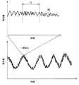
まず、図1を参照して、生体情報のうち、特に血液に関する生体情報の一例である血流情報及び血中の酸素飽和度の測定方法について説明する。 First, a method for measuring blood flow information and oxygen saturation in blood, which is an example of biological information related to blood, among biological information, will be described with reference to FIG.
図1に示すように、血流情報及び血中の酸素飽和度は、患者の体(生体8)に向けて発光素子1から光を照射し、受光素子3で受光した、患者の体内に張り巡らされている動脈4、静脈5、及び毛細血管6等で反射又は透過した光の強さ、すなわち反射光又は透過光の受光量を用いて測定される。 As shown in FIG. 1, blood flow information and blood oxygen saturation are stretched in the patient's body that is irradiated with light from the light emitting element 1 toward the patient's body (living body 8) and received by the
(血流情報の測定)
図2は、受光素子3で受光した反射光の受光量を示すグラフ80の一例である。なお、図2のグラフ80の横軸は時間の経過を表し、縦軸は受光素子3の出力、すなわち受光素子3の受光量を表している。(Measurement of blood flow information)
FIG. 2 is an example of a
図2に示すように、受光素子3の受光量は時間の経過に伴って変化するが、これは血管を含む生体8への光の照射に対して現われる3つの光学現象の影響を受けるためであると考えられる。 As shown in FIG. 2, the amount of light received by the
1つ目の光学現象として、脈動によって、測定している血管内に存在する血液量が変化することによる光の吸収の変化が考えられる。血液には、例えば赤血球等の血球細胞が含まれ、毛細血管6等の血管内を移動するため、血液量が変化することによって血管内を移動する血球細胞の数も変化し、受光素子3での受光量に影響を与えることがある。 As a first optical phenomenon, a change in light absorption due to a change in the amount of blood existing in the blood vessel being measured due to pulsation can be considered. The blood contains blood cells such as red blood cells, and moves in blood vessels such as the
2つ目の光学現象として、ドップラーシフトによる影響が考えられる。 As the second optical phenomenon, the influence of the Doppler shift can be considered.
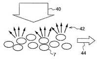
図3に示すように、例えばレーザ光のような周波数ω0のコヒーレント光40を発光素子1から血管の一例である毛細血管6を含む領域に照射した場合、毛細血管6を移動する血球細胞で散乱した散乱光42は、血球細胞の移動速度により決まる差周波Δω0を有するドップラーシフトを生じることになる。一方、血球細胞等の移動体を含まない皮膚等の組織(静止組織)で散乱した散乱光42の周波数は、照射したレーザ光の周波数と同じ周波数ω0を維持する。したがって、毛細血管6等の血管で散乱したレーザ光の周波数ω0+Δω0と、静止組織で散乱したレーザ光の周波数ω0とが互いに干渉し、差周波Δω0を有するビート信号が受光素子3で観測され、受光素子3の受光量が時間の経過に伴って変化する。なお、受光素子3で観測されるビート信号の差周波Δω0は血球細胞の移動速度に依存するが、約数十kHzを上限とした範囲に含まれる。As shown in FIG. 3, for example, when a region including a
また、3つ目の光学現象として、スペックルによる影響が考えられる。 As a third optical phenomenon, the influence of speckle is considered.
図4に示すように、レーザ光のようなコヒーレント光40を、発光素子1から血管中を矢印44の方向に移動する赤血球等の血球細胞7に照射した場合、血球細胞7にぶつかったレーザ光は様々な方向に散乱する。散乱光は位相が異なるためにランダムに干渉し合う。これによりランダムな斑点模様の光強度分布を生じる。このようにして形成される光強度の分布パターンは「スペックルパターン」と呼ばれる。 As shown in FIG. 4, when
既に説明したように、血球細胞7は血管中を移動するため、血球細胞7における光の散乱状態が変化し、スペックルパターンが時間の経過と共に変動する。したがって、受光素子3の受光量が時間の経過に伴って変化する。 As already described, since the blood cell 7 moves in the blood vessel, the light scattering state in the blood cell 7 changes, and the speckle pattern changes with the passage of time. Therefore, the amount of light received by the
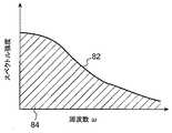
次に、血流情報の求め方の一例について説明する。図2に示す時間経過に伴う受光素子3の受光量が得られた場合、予め定めた単位時間T0の範囲に含まれるデータを切り出し、当該データに対して、例えば高速フーリエ変換(Fast Fourier Transform:FFT)を実行することで、周波数ω毎のスペクトル分布が得られる。図5に、単位時間T0における周波数ω毎のスペクトル分布を示すグラフ82の一例を示す。なお、図5のグラフ82の横軸は周波数ωを表し、縦軸はスペクトル強度を表す。Next, an example of how to obtain blood flow information will be described. When the amount of light received by the
ここで、血液量はグラフ82の横軸と縦軸とで囲まれた斜線領域84で表されるパワースペクトルの面積を全光量で規格化した値に比例する。また、血流速度はグラフ82で表されるパワースペクトルの周波数平均値に比例するため、周波数ωと周波数ωにおけるパワースペクトルの積を周波数ωについて積分した値を斜線領域84の面積で除算した値に比例する。 Here, the blood volume is proportional to the value obtained by normalizing the area of the power spectrum represented by the hatched
なお、血流量は血液量と血流速度の積で表わされるため、上記血液量と血流速度の算出式より求める事が可能である。血流量、血流速度、血液量は血流情報の一例であり、血流情報はこれに限定されない。 In addition, since the blood flow volume is represented by the product of the blood volume and the blood flow velocity, it can be obtained from the calculation formula for the blood volume and the blood flow velocity. Blood flow volume, blood flow velocity, and blood volume are examples of blood flow information, and blood flow information is not limited to this.
図6は、算出した単位時間T0あたりの血流量の変化を示すグラフ86の一例である。なお、図6のグラフ86の横軸は時間を表し、縦軸は血流量を表す。FIG. 6 is an example of a
図6に示すように、血流量は時間と共に変動するが、その変動の傾向は2つの種類に分類される。例えば図6の区間T1における血流量の変動幅88に比べて、区間T2における血流量の変動幅90は大きい。これは、区間T1における血流量の変化が、主に脈の動きに伴う血流量の変化であるのに対して、区間T2における血流量の変化は、例えばうっ血等の原因に伴う血流量の変化を示しているためであると考えられる。As shown in FIG. 6, the blood flow volume varies with time, but the variation tendency is classified into two types. For example, compared to the
(酸素飽和度の測定)
次に、血中の酸素飽和度の測定について説明する。血中の酸素飽和度とは、血液中のヘモグロビンがどの程度酸素と結合しているかを示す指標であり、血中の酸素飽和度が低下するにつれ、貧血等の症状が発生しやすくなる。(Measurement of oxygen saturation)
Next, measurement of blood oxygen saturation will be described. The blood oxygen saturation is an index indicating how much hemoglobin in the blood is bound to oxygen, and symptoms such as anemia are likely to occur as the blood oxygen saturation decreases.
図7は、例えば生体8に吸収される光量の変化を示す概念図である。図7に示すように、生体8における吸光量は、時間の経過と共に変動する傾向が見られる。 FIG. 7 is a conceptual diagram showing changes in the amount of light absorbed by the living body 8, for example. As shown in FIG. 7, the light absorption amount in the living body 8 tends to vary with time.
更に、生体8における吸光の変動に関する内訳について見てみると、主に動脈4によって吸光量が変動し、静脈5及び静止組織を含むその他の組織では、動脈4に比べて吸光量が変動しないとみなせる程度の変動量であることが知られている。これは、心臓から拍出された動脈血は脈波を伴って血管内を移動するため、動脈4が動脈4の断面方向に沿って経時的に伸縮し、動脈4の厚みが変化するためである。なお、図7において、矢印94で示される範囲が、動脈4の厚みの変化に対応した吸光量の変動量を示す。 Further, looking at the breakdown of the change in light absorption in the living body 8, the light absorption amount mainly fluctuates by the artery 4, and the light absorption amount does not fluctuate compared to the artery 4 in other tissues including the vein 5 and the stationary tissue. It is known that the amount of fluctuation can be considered. This is because arterial blood pumped out of the heart moves in the blood vessel with a pulse wave, so that the artery 4 expands and contracts with time along the cross-sectional direction of the artery 4 and the thickness of the artery 4 changes. . In FIG. 7, the range indicated by the
図7において、時刻taにおける受光量をIa、時刻tbにおける受光量をIbとすれば、動脈4の厚みの変化による光の吸光量の変化量ΔAは、(1)式で表される。In FIG. 7, assuming that the amount of received light at time ta is Ia and the amount of received light at time tb is Ib , the amount of change ΔA in the amount of light absorption due to the change in the thickness of the artery 4 can beexpressed by equation (1). Is done.
(数1)
ΔA=ln(Ib/Ia)・・・(1)(Equation 1)
ΔA = ln (Ib / Ia ) (1)
一方、動脈4を流れる酸素と結合したヘモグロビン(酸化ヘモグロビン)は、特に約880nm近辺の波長を有する赤外線(infrared:IR)領域の光を吸収しやすく、酸素と結合していないヘモグロビン(還元ヘモグロビン)は、特に約665nm近辺の波長を有する赤色領域の光を吸収しやすいことが知られている。更に、酸素飽和度は、異なる波長における吸光量の変化量ΔAの比率と比例関係があることが知られている。 On the other hand, hemoglobin (oxygenated hemoglobin) combined with oxygen flowing through the artery 4 easily absorbs light in an infrared (IR) region having a wavelength of about 880 nm, and hemoglobin (reduced hemoglobin) not bonded to oxygen. Is known to easily absorb light in the red region having a wavelength of around 665 nm. Furthermore, it is known that the oxygen saturation is proportional to the ratio of the amount of change ΔA in the amount of absorption at different wavelengths.
したがって、他の波長の組み合わせに比べて。酸化ヘモグロビンと還元ヘモグロビンとで吸光量の差が現われやすい赤外光(IR光)と赤色光を用いて、IR光を生体8に照射した場合の吸光量の変化量ΔAIRと、赤色光を生体8に照射した場合の吸光量の変化量ΔARedとの比率をそれぞれ算出することで、(2)式によって酸素飽和度Sが算出される。なお、(2)においてkは比例定数である。Therefore, compared to other wavelength combinations. Using infrared light (IR light) and red light, in which the difference in light absorption between oxidized hemoglobin and reduced hemoglobin is likely to appear, the amount of change ΔAIR in the amount of light absorption when IR light is irradiated on the living body 8, and the red light By calculating the ratio of the amount of change ΔARed in the amount of light absorbed when the living body 8 is irradiated, the oxygen saturation S is calculated by the equation (2). In (2), k is a proportionality constant.
(数2)
S=k(ΔARed/ΔAIR)・・・(2)(Equation 2)
S = k (ΔARed / ΔAIR ) (2)
すなわち、血中の酸素飽和度を算出する場合、それぞれ異なる波長の光を照射する複数の発光素子1、具体的には、IR光を照射する発光素子1と赤色光を照射する発光素子1とを一部の発光期間が重複しても良いが、望ましくは発光期間が重複しないよう発光させる。そして、各々の発光素子1による反射光又は透過光を受光素子3で受光して、各受光時点における受光量から(1)式及び(2)式、又は、これらの式を変形して得られる公知の式を算出することで、酸素飽和度が測定される。 That is, when calculating oxygen saturation in blood, a plurality of light emitting elements 1 that irradiate light of different wavelengths, specifically, a light emitting element 1 that irradiates IR light and a light emitting element 1 that irradiates red light, However, it is desirable to emit light so that the light emission periods do not overlap. Then, the reflected light or transmitted light from each light emitting element 1 is received by the
上記(1)式を変形して得られる公知の式として、例えば(1)式を展開して、光の吸光量の変化量ΔAを(3)式のように表してもよい。 As a well-known equation obtained by modifying the above equation (1), for example, the equation (1) may be developed and the amount of change ΔA in the amount of light absorption may be expressed as in equation (3).
(数3)
ΔA=lnIb−lnIa・・・(3)(Equation 3)
ΔA = lnIb −lnIa (3)
また、(1)式は(4)式のように変形することができる。 Further, the expression (1) can be modified as the expression (4).
(数4)
ΔA=ln(Ib/Ia)=ln(1+(Ib-Ia)/Ia) ・・・(4)(Equation 4)
ΔA = ln (Ib / Ia ) = ln (1+ (Ib −Ia ) / Ia ) (4)
通常、(Ib-Ia)≪Iaであることから、ln(Ib/Ia)≒(Ib-Ia)/Iaが成り立つため、(1)式の代わりに、光の吸光量の変化量ΔAとして(5)式を用いてもよい。Usually, because it is(I b -I a) «I a , ln order to(I b / I a) ≒ (I b -I a) / I a is satisfied, instead of equation (1), light Equation (5) may be used as the amount of change ΔA in the amount of light absorption.
(数5)
ΔA≒(Ib-Ia)/Ia ・・・(5)(Equation 5)
ΔA≈ (Ib −Ia ) / Ia (5)
なお、IR光を照射する発光素子1と赤色光を照射する発光素子1とを区別して説明する必要がある場合、以降では、IR光を照射する発光素子1を「発光素子LD1」といい、赤色光を照射する発光素子1を「発光素子LD2」というようにする。また、一例として、発光素子LD1を血流量の算出で使用する発光素子1とし、発光素子LD1及び発光素子LD2を、血中の酸素飽和度の算出で利用する発光素子1とする。 When it is necessary to distinguish between the light emitting element 1 that emits IR light and the light emitting element 1 that emits red light, the light emitting element 1 that emits IR light is hereinafter referred to as “light emitting element LD1”. The light emitting element 1 that emits red light is referred to as a “light emitting element LD2”. In addition, as an example, the light emitting element LD1 is used as the light emitting element 1 used for calculating blood flow, and the light emitting element LD1 and the light emitting element LD2 are used as light emitting element 1 used for calculating oxygen saturation in blood.
既に説明したように、血流量の測定では、受光素子3で観測されるビート信号の差周波Δω0は約数十kHzを上限とした範囲に含まれることから、少なくとも差周波Δω0の2倍以上の周波数で発光素子LD1を点滅させ、発光素子LD1からIR光が照射されている発光期間毎に、発光素子LD1による反射光を受光素子3で取得する手法が用いられる場合がある。As already described, in the measurement of the blood flow rate, the difference frequency Δω0 of the beat signal observed by the
この際、図5に示した受光素子3の受光量の変化に対するスペクトル分布のうち、より高い周波数領域におけるスペクトル分布に血流量に関連した重要な生体情報が含まれる場合が多いことから、受光素子3における受光量のサンプリング周期をできるだけ短くすることが好ましい。そのためには、発光素子LD1の単位時間あたりの点滅回数を増加し、発光素子LD1の発光期間に合わせて、生体8で反射した発光素子LD1の受光量を受光素子3で受光すればよい。 At this time, since the biological distribution related to the blood flow is often included in the spectral distribution in the higher frequency region in the spectral distribution with respect to the change in the amount of light received by the
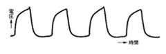
しかし、実際には、発光素子LD1に電圧を印加して、発光素子LD1の印加電圧が発光に必要な電圧に達するまでのタイムラグと、発光素子LD1への印加電圧を停止して、発光素子LD1の印加電圧が0Vになるまでのタイムラグと、が存在する。したがって、発光素子LD1に印加される電圧波形は方形波ではなく、例えば図8に示すように、なだらかに変化する傾向が見られる。 However, in practice, a voltage is applied to the light emitting element LD1 to stop the time lag until the applied voltage of the light emitting element LD1 reaches a voltage necessary for light emission, and the applied voltage to the light emitting element LD1 to stop the light emitting element LD1. There is a time lag until the applied voltage reaches 0V. Therefore, the voltage waveform applied to the light emitting element LD1 is not a square wave, and tends to change gently as shown in FIG.
このように、供給電圧のオン及びオフにどの程度のタイムラグで追従するかを表す電子デバイスの性能を「応答性能」といい、応答性能の高い電子デバイス(この場合、発光素子LD1)ほど、図8に示した波形が方形波に近づき、方形波の上辺では、印加電圧の変動量が予め定めた範囲内に収まるため、安定した光量を有するIR光が照射されることになる。 As described above, the performance of an electronic device that indicates how much time lag it follows to turn on and off the supply voltage is referred to as “response performance”, and the higher the response performance of the electronic device (in this case, the light emitting element LD1), The waveform shown in FIG. 8 approaches a square wave, and the amount of fluctuation of the applied voltage falls within a predetermined range on the upper side of the square wave, so that IR light having a stable light amount is irradiated.
一方、応答性能が悪い電子デバイス(この場合、発光素子LD1)ほど、供給電圧のオン及びオフに伴う波形が乱れやすくなり、安定した光量を有するIR光を生体8に照射することが困難になる。したがって、受光素子3で発光素子LD1からの正しい受光量を取得することが困難になり、血流量の測定の精度を低下させる場合がある。 On the other hand, an electronic device with a poor response performance (in this case, the light emitting element LD1) has a tendency to disturb the waveform associated with turning on and off the supply voltage, and it becomes difficult to irradiate the living body 8 with IR light having a stable light amount. . Therefore, it becomes difficult for the
なお、上記では発光素子LD1を例にして、電子デバイスの応答性能による血流量の測定精度への影響について説明したが、受光素子3等の電子デバイス又は他の電子回路の応答性能が低い場合も、発光素子LD1と同様に血流量の測定精度を低下させる場合がある。 In the above, the light emitting element LD1 is taken as an example to explain the influence of the response performance of the electronic device on the blood flow measurement accuracy. However, the response performance of the electronic device such as the
したがって、発光素子LD1の単位時間あたりの点滅回数を増加しようとしても、例えば発光素子LD1等の電子デバイスの応答性能が制約事項となり、生体情報を精度よく測定することが困難になることが多い。 Therefore, even if the number of blinks per unit time of the light emitting element LD1 is increased, for example, the response performance of an electronic device such as the light emitting element LD1 becomes a restriction, and it is often difficult to accurately measure biological information.
なお、血中の酸素飽和度を測定する場合、受光量の測定周波数は約30Hzから1000Hz程度で十分であることが知られているため、発光素子LD2の1秒あたりの点滅回数を表す発光周波数は約30Hzから1000Hz程度で十分である。すなわち、発光素子LD2の発光周波数を発光素子LD1の発光周波数に合わせ、発光素子LD1と発光素子LD2を交互に発光させる必要はなく、発光素子LD2の発光周波数を、発光素子LD1の発光周波数より低くしてもよい。したがって、血中の酸素飽和度の測定に関しては、血流量の測定に比べて、発光素子LD1の応答性能による測定精度への影響度合いが低くなる。 Note that when measuring the oxygen saturation in the blood, it is known that the measurement frequency of the amount of received light is about 30 Hz to about 1000 Hz. Therefore, the light emission frequency representing the number of blinks per second of the light emitting element LD2 About 30 Hz to about 1000 Hz is sufficient. That is, it is not necessary to match the light emission frequency of the light emitting element LD2 with the light emission frequency of the light emitting element LD1 and cause the light emitting element LD1 and the light emitting element LD2 to emit light alternately, and the light emitting element LD2 has a light emitting frequency lower than the light emitting frequency of the light emitting element LD1. May be. Therefore, regarding the measurement of the oxygen saturation in the blood, the degree of influence on the measurement accuracy by the response performance of the light emitting element LD1 is lower than the measurement of the blood flow rate.
以降では、発光素子LD1及び発光素子LD2を交互に発光させる場合に比べて、複数の生体情報を精度よく測定する生体情報測定装置について説明する。 In the following, a biological information measuring apparatus that measures a plurality of biological information with higher accuracy than when the light emitting elements LD1 and LD2 emit light alternately will be described.
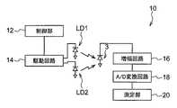
図9は、本実施の形態に係る生体情報測定装置10の構成例を示す図である。 FIG. 9 is a diagram illustrating a configuration example of the biological
図9に示すように、生体情報測定装置10は、制御部12、駆動回路14、増幅回路16、A/D(Analog/Digital)変換回路18、測定部20、発光素子LD1、発光素子LD2、及び受光素子3を備える。 As shown in FIG. 9, the biological
制御部12は、発光素子LD1及び発光素子LD2に駆動電力を供給する電力供給回路を含む駆動回路14に、発光素子LD1及び発光素子LD2の発光周期及び発光期間を制御する制御信号を出力する。 The
駆動回路14は、制御部12からの制御信号を受け付けると、制御信号で指示された発光周期及び発光期間に従って、発光素子LD1及び発光素子LD2に駆動電力を供給し、発光素子LD1及び発光素子LD2を駆動する。 When receiving the control signal from the
増幅回路16は、受光素子3で受光した光の強さに応じた電圧を、A/D変換回路18の入力電圧範囲として規定される電圧レベルまで増幅する。なお、ここでは一例として、受光素子3は受光した光の強さに応じた電圧を出力する素子とするが、受光素子3は受光した光の強さに応じた電流を出力してもよく、この場合、増幅回路16は、A/D変換回路18の入力電流範囲として規定される電流レベルまで、受光素子3が出力する電流を増幅する。 The
A/D変換回路18は、増幅回路16で増幅した電圧を入力として、当該電圧の大きさで表される受光素子3の受光量を数値化して出力する。 The A /
測定部20は、A/D変換回路18で数値化された受光量を入力として、発光素子LD1によって照射された光の受光量に対してFFT処理を行って周波数ω毎のスペクトル分布を算出し、周波数ωと当該周波数ωにおけるスペクトル強度の積を周波数ωについて積分することで、血流量を測定する。 The
また、測定部20は、A/D変換回路18で数値化された受光量を入力として、発光素子LD1及び発光素子LD2によって照射された光の受光量を、それぞれ時系列順に管理する。そして、測定部20は、発光素子LD1の吸光量の変化量ΔAIR、及び発光素子LD2の吸光量の変化量ΔARedを(1)式に従って算出し、吸光量の変化量ΔAIRに対する吸光量の変化量ΔARedの割合を(2)式に従って算出することで、酸素飽和度を測定する。In addition, the
図10に、生体情報測定装置10における発光素子LD1、発光素子LD2、及び受光素子3の配置例を示す。図10に示すように、発光素子LD1、発光素子LD2、及び受光素子3は、生体8の一方の面に向かって並べて配置される。この場合、受光素子3は、生体8で反射された発光素子LD1及び発光素子LD2の光を受光する。 FIG. 10 shows an arrangement example of the light emitting element LD 1, the light emitting element LD 2, and the
しかし、発光素子LD1、発光素子LD2、及び受光素子3の配置は、図10の配置例に限定されない。例えば、図11に示すように、発光素子LD1及び発光素子LD2と、受光素子3とを、生体8を挟んで対向する位置に配置するようにしてもよい。この場合、受光素子3は、生体8を透過した発光素子LD1及び発光素子LD2の光を受光する。 However, the arrangement of the light emitting element LD1, the light emitting element LD2, and the
なお、ここでは一例として、発光素子LD1及び発光素子LD2は、共に面発光レーザ素子であるものとして説明するが、これに限らず、端面発光レーザ素子であってもよい。 Here, as an example, the light-emitting element LD1 and the light-emitting element LD2 are described as both surface-emitting laser elements. However, the present invention is not limited to this, and may be edge-emitting laser elements.
測定部20において血流量を測定する場合、既に説明したように、ビート信号による受光量のスペクトル分布を利用するため、発光素子LD1には他の光に比べてビート信号が発生しやすいレーザ素子を用いることが好ましい。 When measuring the blood flow in the
しかし、発光素子LD2から照射される光はレーザ光でなくても、発光素子LD2の吸光量の変化量ΔARedは算出されるため、発光素子LD2には、発光ダイオード(Light-Emitting Diode:LED)又は有機発光ダイオード(Organic Light-Emitting Diode:OLED)を用いてもよい。However, even if the light emitted from the light emitting element LD2 is not laser light, the change amount ΔARed of the light absorption amount of the light emitting element LD2 is calculated, and therefore, the light emitting element LD2 includes a light-emitting diode (LED). ) Or organic light-emitting diode (OLED) may be used.
次に、図12を参照して、本実施の形態に係る生体情報測定装置10の電気系統の要部構成について説明する。 Next, with reference to FIG. 12, the principal part structure of the electric system of the biological
図12に示すように、本実施の形態に係る生体情報測定装置10は、発光素子LD1及び発光素子LD2の発光周期及び発光期間を制御する制御手段、並びに、生体8における血流量及び血中の酸素飽和度を測定する測定手段の一例としてのCPU(Central Processing Unit)30を備える。また、生体情報測定装置10は、各種プログラムや各種パラメータ等が予め記憶されたROM(Read Only Memory)32、及びCPU30による各種プログラムの実行時のワークエリア等として用いられるRAM(Random Access Memory)34を備える。 As shown in FIG. 12, the biological
CPU30、ROM32、及びRAM32は、生体情報測定装置10の内部バス36で互いに接続され、更に、内部バス36には、発光素子LD1、発光素子LD2、受光素子3、増幅回路16、及びA/D変換回路18が各々接続される。なお、CPU30には、指定した時点からの経過時間を計測するタイマが内蔵されている。 The
次に、図13を参照して、生体情報測定装置10の作用について説明する。 Next, the operation of the biological
図13は、CPU30が生体情報の測定を開始する指示を受け付けた場合に、CPU30によって実行される生体情報測定処理の流れの一例を示すフローチャートである。生体情報測定処理を規定するプログラム(生体情報測定プログラム)は、例えばROM32に予めインストールされている。なお、生体情報測定プログラムの開始時点において、発光素子LD1及び発光素子LD2は、共にレーザ光を照射していない発光停止状態になっているものとする。 FIG. 13 is a flowchart illustrating an example of a flow of a biological information measurement process executed by the
まず、ステップS10において、CPU30は、CPU30に内蔵されるタイマAをリセットする。ここで、タイマをリセットするとは、タイマによる計測を停止し、タイマを停止した時点から新たに経過時間を計測し始めることを意味する。 First, in step S10, the
ステップS20において、CPU30は、駆動回路14に対して発光素子LD1の発光開始を指示する発光開始指示を通知する。駆動回路14は、発光開始指示を受け付けると発光素子LD1に駆動電力を供給し、発光素子LD1からレーザ光を照射させる。 In step S20, the
ステップS30において、CPU30は、受光素子3で受光した発光素子LD1による受光量をA/D変換回路18から取得して、例えばRAM34の予め定めた領域に記憶する。 In step S <b> 30, the
ステップS40において、CPU30は、ステップS10でタイマAをリセットしてから時間T3以上経過しているか否かを判定する。当該時間T3は、例えばROM32の予め定めた領域に予め記憶されるパラメータであり、発光素子LD1の発光期間の長さを決定する。In step S40,
ステップS40の判定処理が否定判定の場合には、ステップS30に移行する。そして、CPU30は、時間T3以上経過するまで、ステップS30で、受光素子3で受光した発光素子LD1による受光量をA/D変換回路18から取得する処理を繰り返し実行する。すなわち、CPU30は、発光素子LD1を時間T3以上に亘って発光させ続けた状態で、発光素子LD1による受光量を複数回取得する。If the determination process in step S40 is negative, the process proceeds to step S30. Then,
一方、ステップS40の判定処理が肯定判定の場合には、ステップS50に移行する。 On the other hand, if the determination process in step S40 is affirmative, the process proceeds to step S50.
ステップS50において、CPU30は、駆動回路14に対して発光素子LD1の発光停止を指示する発光停止指示を通知する。駆動回路14は、発光停止指示を受け付けると発光素子LD1への駆動電力の供給を停止し、発光素子LD1によるレーザ光の照射を停止させる。 In step S50, the
ステップS60において、CPU30は、CPU30に内蔵されるタイマBをリセットする。 In step S60, the
ステップS70において、CPU30は、駆動回路14に対して発光素子LD2の発光開始指示を通知する。駆動回路14は、発光開始指示を受け付けると発光素子LD2に駆動電力を供給し、発光素子LD2からレーザ光を照射させる。 In step S70, the
ステップS80において、CPU30は、受光素子3で受光した発光素子LD2による受光量をA/D変換回路18から取得して、例えばRAM34の予め定めた領域に記憶する。 In step S80, the
ステップS90において、CPU30は、ステップS60でタイマBをリセットしてから時間T4以上経過しているか否かを判定する。当該時間T4は、例えばROM32の予め定めた領域に予め記憶されるパラメータであり、発光素子LD2の発光期間の長さを決定する。In step S90,
なお、既に説明したように、血中の酸素飽和度を測定する際に必要となる発光素子LD2の受光量の測定周期は、血流量を測定する際に必要となる発光素子LD1の受光量の測定周期より短くてもよいため、時間T4を時間T3より小さい値に設定して、発光素子LD2の発光期間を発光素子LD1の発光期間より短くすることが好ましい。このように時間T4を設定することで、時間T4を時間T3より大きい値に設定する場合に比べて、血中の酸素飽和度の測定精度を低下させることなく、単位時間における血中の酸素飽和度の測定回数を増加することができる。As already described, the measurement period of the amount of light received by the light emitting element LD2 required when measuring the oxygen saturation in the blood is the amount of light received by the light emitting element LD1 required when measuring the blood flow. Since it may be shorter than the measurement cycle, it is preferable to set the time T4 to a value smaller than the time T3 so that the light emitting period of the light emitting element LD2 is shorter than the light emitting period of the light emitting element LD1. By setting the time T4 in this way, the blood in the unit time can be reduced without degrading the measurement accuracy of the oxygen saturation in the blood as compared with the case where the time T4 is set to a value larger than the time T3. The number of oxygen saturation measurements can be increased.
ステップS90の判定処理が否定判定の場合、CPU30はステップS90の処理を繰り返し実行して、タイマBが時間T4以上経過するまで待機する。一方、肯定判定の場合にはステップS100に移行する。If the determination processing in step S90 is negative determination,
ステップS100において、CPU30は、駆動回路14に対して発光素子LD2の発光停止を指示する発光停止指示を通知する。駆動回路14は、発光停止指示を受け付けると発光素子LD2への駆動電力の供給を停止し、発光素子LD2によるレーザ光の照射を停止させる。 In step S100, the
ステップS110において、CPU30は、既に説明した血流量の測定方法にしたがって、ステップS30で取得した発光素子LD1の各受光量の時系列データに対してFFT処理を行い、周波数ω毎のスペクトル分布を算出し、当該スペクトル分布を全周波数ωについて積分することで、血流量を測定する。 In step S110, the
ステップS120において、CPU30は、既に説明した血中の酸素飽和度の測定方法にしたがって、ステップS30で最後に取得した発光素子LD1の受光量と、ステップS80で取得した発光素子LD2の受光量と、を組み合わせた受光量ペアを、例えばRAM34の予め定めた領域に記憶する。そして、CPU30は、受光量ペアの時系列データを用いて(1)式及び(2)式、又は、これらの式を変形して得られる公知の式を算出することで、血中の酸素飽和度を測定する。 In step S120, according to the method for measuring blood oxygen saturation already described, the
ステップS130において、CPU30は、生体情報の測定を終了する終了指示を受け付けたか否かを判定する。当該判定処理が否定判定の場合にはステップS10に移行し、終了指示を受け付けるまでステップS10〜S130を繰り返し実行することで、血流量及び酸素飽和度を測定し続ける。 In step S <b> 130, the
図14は、図13の生体情報測定プログラムを実行した場合における、発光素子LD1及び発光素子LD2の発光タイミングを示すタイミングチャートの一例である。 FIG. 14 is an example of a timing chart showing light emission timings of the light emitting element LD1 and the light emitting element LD2 when the biological information measurement program of FIG. 13 is executed.
図14に示すように、発光素子LD1には、時間T3の長さを有する発光期間と、時間T4の長さを有する発光停止期間とが繰り返し現われる。反対に、発光素子LD2には、時間T3の長さを有する発光停止期間と、時間T4の長さを有する発光期間とが繰り返し現われる。As shown in FIG. 14, in the light emitting element LD1, a light emission period having a length of time T3 and a light emission stop period having a length of time T4 appear repeatedly. Conversely, the light emitting element LD2, the light emission stop period having a length of time T3, repeatedly appears and light emission period with a length of time T4.
また、図13のステップS30及びS40の処理によって、生体情報測定装置10は、発光素子LD1からレーザ光を連続して照射した状態のまま、複数の受光点96で発光素子LD1の受光量を取得する。 Further, through the processing of steps S30 and S40 in FIG. 13, the biological
したがって、血流量を測定する際、図15に示すように、発光素子LD1の単位時間あたりの点滅回数を増加し、発光素子LD1の各々の発光期間毎に1つ設けた受光点96で発光素子LD1の受光量を取得することで、発光素子LD1の受光量のサンプリング周期を短くする場合に比べて、発光素子LD1の点滅に伴う発光素子LD1の応答性能の影響を受けにくくなる。すなわち、生体情報測定装置10は、発光素子LD1の単位時間あたりの点滅回数を増加することで、発光素子LD1の受光量のサンプリング周期を短くする場合よりも、当該サンプリング周期を更に短くすることができる。 Therefore, when measuring the blood flow rate, as shown in FIG. 15, the number of flashes per unit time of the light emitting element LD1 is increased, and the
なお、ここでレーザ光を連続して照射する状態とは、上記に示したように、例えば発光素子LD1の発光期間全域に亘って、発光素子LD1からレーザ光を照射する状態に限られない。例えば、発光素子LD1の受光量のサンプリング周期に合わせて発光素子LD1からレーザ光を照射し、且つ、各受光点96における発光素子LD1のレーザ光の光量が、発光素子LD1のオンオフ制御に伴う発光素子LD1の応答性能に影響されない範囲で、発光素子LD1からのレーザ光の照射を一旦停止し、その後、レーザ光の照射を再開する状態も含まれる。 Here, the state in which the laser light is continuously irradiated is not limited to the state in which the laser light is irradiated from the light emitting element LD1 over the entire light emission period of the light emitting element LD1, for example, as described above. For example, the laser light is emitted from the light emitting element LD1 in accordance with the sampling period of the light receiving amount of the light emitting element LD1, and the light amount of the laser light of the light emitting element LD1 at each
また、生体情報測定装置10の測定部20は、発光素子LD1及び発光素子LD2の受光量の各取得タイミングを表す受光点96のうち、受光点96Bで取得した発光素子LD2の受光量と、受光点96Bを含む発光素子LD2の発光期間と時間軸に沿って隣接する発光素子LD1の発光期間中に取得した何れかの受光点96における発光素子LD1の受光量を用いて、血中の酸素飽和度を測定する。なお、この場合には、受光点96Bに隣接する、受光点96A又は受光点96Cの何れか一方における発光素子LD1の受光量を、受光点96Bにおける発光素子LD2の受光量と組み合わせることが好ましい。 In addition, the
これは、血中の酸素飽和度を測定する場合、時間的にできるだけ隣接する発光素子LD1の受光量と発光素子LD2の受光量とを用いた方が、測定精度が高くなる傾向があるためである。 This is because when measuring the oxygen saturation in blood, the measurement accuracy tends to be higher when the light receiving amount of the light emitting element LD1 and the light receiving amount of the light emitting element LD2 that are adjacent in terms of time are used. is there.
また、図13に示した生体情報測定プログラムのフローチャートでは、発光素子LD2の発光期間に発光素子LD2の受光量を1回取得する例を示したが、複数回取得するようにしてもよい。 Further, in the flowchart of the biological information measurement program illustrated in FIG. 13, an example in which the received light amount of the light emitting element LD2 is acquired once during the light emission period of the light emitting element LD2, but may be acquired a plurality of times.
図16は、発光素子LD2の発光期間に発光素子LD2の受光量を複数回取得する場合の取得タイミングを示すタイミングチャートの一例である。図16に示す例では、領域92で示される発光素子LD2の発光期間に、発光素子LD2の受光量を3回取得している。なお、発光素子LD2の受光量の取得回数は3回に限られず、2回以上であればよいことは言うまでもない。 FIG. 16 is an example of a timing chart showing the acquisition timing when the amount of light received by the light emitting element LD2 is acquired a plurality of times during the light emission period of the light emitting element LD2. In the example shown in FIG. 16, the amount of light received by the light emitting element LD2 is acquired three times during the light emission period of the light emitting element LD2 indicated by the
この場合、測定部20は、領域92で示される発光素子LD2の発光期間に取得した各受光点96における受光量の平均値を、領域92で示される発光素子LD2の発光期間における受光量とする。また、測定部20は、発光素子LD2の発光期間に隣接する発光素子LD1の発光期間で取得した各受光点96における受光量の平均値を、発光素子LD1の発光期間における受光量とする。そして、測定部20は、発光素子LD1の発光期間における受光量と、発光素子LD2の発光期間における受光量と、を組み合わせて、血中の酸素飽和度を算出する。 In this case, the
なお、発光素子LD1の発光期間における複数の受光点96の選択方法に制限はないが、出来る限り、領域92で示される発光素子LD2の発光期間における受光点96と隣接する受光点96を選択することが好ましい。例えば領域92に含まれる受光点96の数と同じ数の受光点96を有する、領域98又は領域99に含まれる受光点96を選択すればよい。これは、既に述べたように、血中の酸素飽和度を測定する場合、時間的にできるだけ隣接する発光素子LD1の受光量と発光素子LD2の受光量とを用いた方が、測定精度が高くなる傾向があるためである。 Although there is no limitation on the selection method of the plurality of light receiving points 96 in the light emitting period of the light emitting element LD1, the
また、血中の酸素飽和度の算出に用いる、発光素子LD1の発光期間における受光点96の選択数にも制限はない。図16に示す例では、領域92で示される発光素子LD2の発光期間における受光点96の数と同じ数の受光点96を選択しているが、例えば図17の領域98A又は領域99Aで示されるように、発光素子LD1の1つの発光期間に含まれる全ての受光点96を選択してもよい。選択する発光素子LD1の受光点96の数を増やすほど、発光素子LD1から受光したIR光に含まれるビート信号の差周波Δω0が平均化されて、血中の酸素飽和度の算出に対して雑音成分となるビート信号の影響が低減される。In addition, there is no limit to the number of light receiving points 96 that are used to calculate the oxygen saturation level in blood during the light emission period of the light emitting element LD1. In the example shown in FIG. 16, the same number of light receiving points 96 as the number of light receiving points 96 in the light emission period of the light emitting element LD2 indicated by the
このように本実施の形態に係る生体情報測定装置10によれば、発光素子LD1からレーザ光を照射した状態のまま、複数の受光点96で発光素子LD1の受光量を取得する。 As described above, according to the biological
したがって、単位時間あたりの発光素子LD1の点滅回数を増加することで、生体8で反射した光の受光量のサンプリング周期を短くする場合に比べて、更に受光量のサンプリング周期を短くすることができるため、生体情報を精度よく測定することができる。 Therefore, by increasing the number of blinks of the light emitting element LD1 per unit time, the sampling period of the received light amount can be further shortened compared with the case where the sampling period of the received light amount reflected by the living body 8 is shortened. Therefore, biological information can be measured with high accuracy.
また、生体情報測定装置10は、ここで挙げた内容に限らず、他の生体情報の測定にも利用する事が出来る。 In addition, the biological
なお、生体情報測定装置10は、既に説明したように血流量の他、血流速度の測定にも適用される。また、図7に示したように、動脈4の脈動に応じて受光素子3で受光される受光量が変化するため、受光素子3での受光量の変化から、脈拍数が測定される。また、脈拍数の変化を時系列順に測定して得られる波形を2回微分することで、加速度脈波が測定される。加速度脈波は、血管年齢の推定又は動脈硬化の診断等に用いられる。 In addition, the biological
また、生体情報測定装置10は、ここで挙げた内容に限らず、他の生体情報の測定にも利用する事ができる。In addition, the biological
以上、実施の形態を用いて本発明について説明したが、本発明は実施の形態に記載の範囲には限定されない。本発明の要旨を逸脱しない範囲で実施の形態に多様な変更又は改良を加えることができ、当該変更又は改良を加えた形態も本発明の技術的範囲に含まれる。例えば、本発明の要旨を逸脱しない範囲で処理の順序を変更してもよい。 Although the present invention has been described using the embodiment, the present invention is not limited to the scope described in the embodiment. Various changes or improvements can be added to the embodiments without departing from the gist of the present invention, and embodiments to which the changes or improvements are added are also included in the technical scope of the present invention. For example, the processing order may be changed without departing from the scope of the present invention.
また、実施の形態では、一例として制御部12及び測定部20における処理をソフトウエアで実現する形態について説明したが、図13に示したフローチャートと同等の処理をハードウエアで処理させるようにしてもよい。この場合、制御部12及び測定部20における処理をソフトウエアで実現する場合に比べて、処理の高速化が図られる。 In the embodiment, as an example, the form in which the processing in the
また、実施の形態では、生体情報測定プログラムがROM32にインストールされている形態を説明したが、これに限定されるものではない。本発明に係る生体情報測定プログラムは、コンピュータ読取可能な記録媒体に記録された形態で提供することも可能である。例えば、本発明に係る生体情報測定プログラムは、CD(Compact Disc)−ROM、DVD(Digital Versatile)−ROMまたはUSB(Universal Serial Bus)メモリ等の可搬型記録媒体に記録された形態で提供することも可能である。また、本発明に係る生体情報測定プログラムは、フラッシュメモリ等の半導体メモリ等に記録された形態で提供することも可能である。 In the embodiment, the biological information measurement program is installed in the
1、2・・・発光素子(LD)
3・・・受光素子
4・・・動脈
5・・・静脈
6・・・毛細血管
7・・・血球細胞
8・・・生体
10・・・生体情報測定装置
12・・・制御部
14・・・駆動回路
16・・・増幅回路
18・・・変換回路
20・・・測定部
30・・・CPU
96(96A、96B、96C)・・・受光点1, 2 ... Light emitting element (LD)
DESCRIPTION OF
96 (96A, 96B, 96C) ... light receiving point
Claims (7)
Translated fromJapanese前記第1発光素子及び前記第2発光素子から照射される各々の光を受光する受光素子と、
前記第1発光素子の連続発光期間より前記第2発光素子の連続発光期間が短くなるように、前記第1発光素子及び前記第2発光素子の発光期間を制御する制御手段と、
前記受光素子で受光した光の各々から、複数の生体情報を測定する測定手段と、
備えた生体情報測定装置。A first light emitting element and a second light emitting element that irradiate light having different wavelengths;
A light receiving element that receives each light emitted from the first light emitting element and the second light emitting element;
Control means for controlling a light emission period of the first light emitting element and the second light emitting element so that a continuous light emission period of the second light emitting element is shorter than a continuous light emission period of the first light emitting element;
Measuring means for measuring a plurality of biological information from each of the light received by the light receiving element;
Biological information measuring device provided.
請求項1に記載の生体情報測定装置。The measuring means receives the amount of light received by the first light emitting element received by the light receiving element a plurality of times for each light emitting period of the first light emitting element, and the second light emission adjacent to the light emitting period of the first light emitting element. The biological information measuring device according to claim 1, wherein a plurality of pieces of biological information are measured using the amount of light received during the light emission period of the element.
請求項1又は請求項2に記載の生体情報測定装置。3. The control unit according to claim 1, wherein the control unit controls a light emission period of the first light emitting element and the second light emitting element so that light emission periods of the first light emitting element and the second light emitting element do not overlap. The biological information measuring device described.
請求項1〜請求項3の何れか1項に記載の生体情報測定装置。The measuring means includes a frequency spectrum with respect to the amount of light received by the first light-emitting element received by the light-receiving element, a light-receiving amount of light by the first light-emitting element received by the light-receiving element, and the second light-emitting element. The biological information measuring device according to any one of claims 1 to 3, wherein the plurality of pieces of biological information are measured from an amount of received light.
請求項1〜請求項4の何れか1項に記載の生体情報測定装置。The measuring means obtains the received light amount from the light receiving element a plurality of times during at least one of the light emitting period of the first light emitting element and the light emitting period of the second light emitting element, and averages the respective received light amounts. The biological information measuring device according to claim 1, wherein the value is a light reception amount of light during a light emission period in which the light reception amount is acquired from the light receiving element over a plurality of times.
請求項1〜請求項5の何れか1項に記載の生体情報測定装置。The measurement means measures biological information including at least one of a blood flow volume, a blood flow velocity, and a blood volume, and oxygen saturation in the blood as the plurality of biological information. The biological information measuring device according to claim 1.
Priority Applications (7)
| Application Number | Priority Date | Filing Date | Title |
|---|---|---|---|
| JP2016064455AJP2017176264A (en) | 2016-03-28 | 2016-03-28 | Biological information measuring device and biological information measuring program |
| US15/226,371US10376223B2 (en) | 2016-03-28 | 2016-08-02 | Living-body information measurement device and non-transitory computer readable medium |
| US15/228,074US20170273631A1 (en) | 2016-03-28 | 2016-08-04 | Living-body information measurement device |
| US15/229,192US10492732B2 (en) | 2016-03-28 | 2016-08-05 | Living-body information measurement device and non-transitory computer readable medium |
| CN201610806366.7ACN107233100A (en) | 2016-03-28 | 2016-09-07 | Biological information detecting device |
| CN201610808043.1ACN107233089B (en) | 2016-03-28 | 2016-09-07 | Living body information measuring device |
| CN201610810705.9ACN107233073A (en) | 2016-03-28 | 2016-09-08 | Biological information detecting device |
Applications Claiming Priority (1)
| Application Number | Priority Date | Filing Date | Title |
|---|---|---|---|
| JP2016064455AJP2017176264A (en) | 2016-03-28 | 2016-03-28 | Biological information measuring device and biological information measuring program |
Publications (1)
| Publication Number | Publication Date |
|---|---|
| JP2017176264Atrue JP2017176264A (en) | 2017-10-05 |
Family
ID=60002875
Family Applications (1)
| Application Number | Title | Priority Date | Filing Date |
|---|---|---|---|
| JP2016064455APendingJP2017176264A (en) | 2016-03-28 | 2016-03-28 | Biological information measuring device and biological information measuring program |
Country Status (1)
| Country | Link |
|---|---|
| JP (1) | JP2017176264A (en) |
Cited By (2)
| Publication number | Priority date | Publication date | Assignee | Title |
|---|---|---|---|---|
| WO2020122164A1 (en)* | 2018-12-14 | 2020-06-18 | ソニー株式会社 | Biosignal measurement apparatus |
| WO2024117209A1 (en)* | 2022-11-30 | 2024-06-06 | 株式会社ジャパンディスプレイ | Detection device |
Citations (12)
| Publication number | Priority date | Publication date | Assignee | Title |
|---|---|---|---|---|
| JPH01256924A (en)* | 1988-04-08 | 1989-10-13 | Kowa Co | Ophthalmological diagnostic method and device |
| JPH04193158A (en)* | 1990-11-27 | 1992-07-13 | Kowa Co | Blood flow measuring device |
| JPH07171140A (en)* | 1993-12-21 | 1995-07-11 | Kowa Co | Oxygen saturation measuring device |
| JPH07265284A (en)* | 1994-03-30 | 1995-10-17 | Nippon Koden Corp | Oxygen saturation and blood flow measurement device |
| JPH09103425A (en)* | 1995-08-31 | 1997-04-22 | Hewlett Packard Co <Hp> | Medical monitoring method |
| JP2002168862A (en)* | 2000-12-04 | 2002-06-14 | Terumo Corp | Apparatus for measuring body fluid |
| JP2007135621A (en)* | 2005-11-14 | 2007-06-07 | Konica Minolta Sensing Inc | Biological information measuring instrument |
| JP2009189576A (en)* | 2008-02-14 | 2009-08-27 | Univ Of Tsukuba | Blood flow measuring device and brain activity measuring device using blood flow measuring device |
| JP2010233908A (en)* | 2009-03-31 | 2010-10-21 | Konica Minolta Sensing Inc | Pulse oximeter |
| JP2011041699A (en)* | 2009-08-21 | 2011-03-03 | Konica Minolta Sensing Inc | Biological information measuring apparatus |
| US20120277559A1 (en)* | 2009-12-08 | 2012-11-01 | Matthias Kohl-Bareis | Apparatus for Measuring Blood Parameters |
| JP2015528334A (en)* | 2012-08-10 | 2015-09-28 | ビオプティックス・インコーポレイテッドVioptix,Inc. | Wireless and handheld tissue oximetry devices |
- 2016
- 2016-03-28JPJP2016064455Apatent/JP2017176264A/enactivePending
Patent Citations (12)
| Publication number | Priority date | Publication date | Assignee | Title |
|---|---|---|---|---|
| JPH01256924A (en)* | 1988-04-08 | 1989-10-13 | Kowa Co | Ophthalmological diagnostic method and device |
| JPH04193158A (en)* | 1990-11-27 | 1992-07-13 | Kowa Co | Blood flow measuring device |
| JPH07171140A (en)* | 1993-12-21 | 1995-07-11 | Kowa Co | Oxygen saturation measuring device |
| JPH07265284A (en)* | 1994-03-30 | 1995-10-17 | Nippon Koden Corp | Oxygen saturation and blood flow measurement device |
| JPH09103425A (en)* | 1995-08-31 | 1997-04-22 | Hewlett Packard Co <Hp> | Medical monitoring method |
| JP2002168862A (en)* | 2000-12-04 | 2002-06-14 | Terumo Corp | Apparatus for measuring body fluid |
| JP2007135621A (en)* | 2005-11-14 | 2007-06-07 | Konica Minolta Sensing Inc | Biological information measuring instrument |
| JP2009189576A (en)* | 2008-02-14 | 2009-08-27 | Univ Of Tsukuba | Blood flow measuring device and brain activity measuring device using blood flow measuring device |
| JP2010233908A (en)* | 2009-03-31 | 2010-10-21 | Konica Minolta Sensing Inc | Pulse oximeter |
| JP2011041699A (en)* | 2009-08-21 | 2011-03-03 | Konica Minolta Sensing Inc | Biological information measuring apparatus |
| US20120277559A1 (en)* | 2009-12-08 | 2012-11-01 | Matthias Kohl-Bareis | Apparatus for Measuring Blood Parameters |
| JP2015528334A (en)* | 2012-08-10 | 2015-09-28 | ビオプティックス・インコーポレイテッドVioptix,Inc. | Wireless and handheld tissue oximetry devices |
Cited By (3)
| Publication number | Priority date | Publication date | Assignee | Title |
|---|---|---|---|---|
| WO2020122164A1 (en)* | 2018-12-14 | 2020-06-18 | ソニー株式会社 | Biosignal measurement apparatus |
| US12109011B2 (en) | 2018-12-14 | 2024-10-08 | Sony Group Corporation | Biological signal measuring device |
| WO2024117209A1 (en)* | 2022-11-30 | 2024-06-06 | 株式会社ジャパンディスプレイ | Detection device |
Similar Documents
| Publication | Publication Date | Title |
|---|---|---|
| US10492732B2 (en) | Living-body information measurement device and non-transitory computer readable medium | |
| KR102486700B1 (en) | Apparatus and method for estimating blood pressure | |
| US20100056887A1 (en) | Emission sensor device and bioinformation detecting method | |
| US10271747B2 (en) | Living-body information measuring device | |
| EP3485807A1 (en) | Measurement device, measurement method, and measurement program | |
| US20180014731A1 (en) | Biometric information measuring apparatus and non-transitory computer readable storage medium | |
| US11160473B2 (en) | Biological information measurement device and non-transitory computer readable medium | |
| US10492695B2 (en) | Living-body information measuring device and light-emitting element | |
| US20180014735A1 (en) | Biometric information measuring apparatus and non-transitory computer readable storage medium | |
| JP2017176264A (en) | Biological information measuring device and biological information measuring program | |
| JP2017176263A (en) | Biological information measuring device and biological information measuring program | |
| JP7247671B2 (en) | Biological information measuring device and biological information measuring program | |
| JP7024261B2 (en) | Optical measuring device and optical measuring program | |
| JP7102832B2 (en) | Biological information measuring device | |
| JP7106893B2 (en) | Biological information measuring device | |
| JP2023043576A (en) | Biological information measurement device and biological information measurement program | |
| JP6711071B2 (en) | Biological information measuring device and biological information measuring program | |
| JP2019141410A (en) | Biological information measurement device and biological information measurement program | |
| JP2016198206A (en) | Blood oxygen status monitoring apparatus and monitoring method | |
| JP2018115946A (en) | Measuring device, measuring method, computer program, and recording medium | |
| JP2018117968A (en) | Biological signal analysis device and control method therefor |
Legal Events
| Date | Code | Title | Description |
|---|---|---|---|
| A621 | Written request for application examination | Free format text:JAPANESE INTERMEDIATE CODE: A621 Effective date:20190228 | |
| A977 | Report on retrieval | Free format text:JAPANESE INTERMEDIATE CODE: A971007 Effective date:20200115 | |
| A131 | Notification of reasons for refusal | Free format text:JAPANESE INTERMEDIATE CODE: A131 Effective date:20200212 | |
| A521 | Request for written amendment filed | Free format text:JAPANESE INTERMEDIATE CODE: A523 Effective date:20200409 | |
| A131 | Notification of reasons for refusal | Free format text:JAPANESE INTERMEDIATE CODE: A131 Effective date:20200707 | |
| A521 | Request for written amendment filed | Free format text:JAPANESE INTERMEDIATE CODE: A523 Effective date:20200902 | |
| A131 | Notification of reasons for refusal | Free format text:JAPANESE INTERMEDIATE CODE: A131 Effective date:20201013 | |
| A02 | Decision of refusal | Free format text:JAPANESE INTERMEDIATE CODE: A02 Effective date:20210413 |