JP2017175874A - Actuator and tactile sensation presentation device - Google Patents
Actuator and tactile sensation presentation deviceDownload PDFInfo
- Publication number
- JP2017175874A JP2017175874AJP2016062430AJP2016062430AJP2017175874AJP 2017175874 AJP2017175874 AJP 2017175874AJP 2016062430 AJP2016062430 AJP 2016062430AJP 2016062430 AJP2016062430 AJP 2016062430AJP 2017175874 AJP2017175874 AJP 2017175874A
- Authority
- JP
- Japan
- Prior art keywords
- diaphragm
- piezoelectric element
- actuator
- support portion
- vibration
- Prior art date
- Legal status (The legal status is an assumption and is not a legal conclusion. Google has not performed a legal analysis and makes no representation as to the accuracy of the status listed.)
- Granted
Links
Images


Classifications
- H—ELECTRICITY
- H10—SEMICONDUCTOR DEVICES; ELECTRIC SOLID-STATE DEVICES NOT OTHERWISE PROVIDED FOR
- H10N—ELECTRIC SOLID-STATE DEVICES NOT OTHERWISE PROVIDED FOR
- H10N30/00—Piezoelectric or electrostrictive devices
- H10N30/20—Piezoelectric or electrostrictive devices with electrical input and mechanical output, e.g. functioning as actuators or vibrators
- H10N30/202—Piezoelectric or electrostrictive devices with electrical input and mechanical output, e.g. functioning as actuators or vibrators using longitudinal or thickness displacement combined with bending, shear or torsion displacement
- B—PERFORMING OPERATIONS; TRANSPORTING
- B06—GENERATING OR TRANSMITTING MECHANICAL VIBRATIONS IN GENERAL
- B06B—METHODS OR APPARATUS FOR GENERATING OR TRANSMITTING MECHANICAL VIBRATIONS OF INFRASONIC, SONIC, OR ULTRASONIC FREQUENCY, e.g. FOR PERFORMING MECHANICAL WORK IN GENERAL
- B06B1/00—Methods or apparatus for generating mechanical vibrations of infrasonic, sonic, or ultrasonic frequency
- B06B1/02—Methods or apparatus for generating mechanical vibrations of infrasonic, sonic, or ultrasonic frequency making use of electrical energy
- B06B1/06—Methods or apparatus for generating mechanical vibrations of infrasonic, sonic, or ultrasonic frequency making use of electrical energy operating with piezoelectric effect or with electrostriction
- B06B1/0644—Methods or apparatus for generating mechanical vibrations of infrasonic, sonic, or ultrasonic frequency making use of electrical energy operating with piezoelectric effect or with electrostriction using a single piezoelectric element
- B06B1/0662—Methods or apparatus for generating mechanical vibrations of infrasonic, sonic, or ultrasonic frequency making use of electrical energy operating with piezoelectric effect or with electrostriction using a single piezoelectric element with an electrode on the sensitive surface
- B06B1/0666—Methods or apparatus for generating mechanical vibrations of infrasonic, sonic, or ultrasonic frequency making use of electrical energy operating with piezoelectric effect or with electrostriction using a single piezoelectric element with an electrode on the sensitive surface used as a diaphragm
- G—PHYSICS
- G06—COMPUTING OR CALCULATING; COUNTING
- G06F—ELECTRIC DIGITAL DATA PROCESSING
- G06F3/00—Input arrangements for transferring data to be processed into a form capable of being handled by the computer; Output arrangements for transferring data from processing unit to output unit, e.g. interface arrangements
- G06F3/01—Input arrangements or combined input and output arrangements for interaction between user and computer
- G06F3/016—Input arrangements with force or tactile feedback as computer generated output to the user
- G—PHYSICS
- G06—COMPUTING OR CALCULATING; COUNTING
- G06F—ELECTRIC DIGITAL DATA PROCESSING
- G06F3/00—Input arrangements for transferring data to be processed into a form capable of being handled by the computer; Output arrangements for transferring data from processing unit to output unit, e.g. interface arrangements
- G06F3/01—Input arrangements or combined input and output arrangements for interaction between user and computer
- G06F3/03—Arrangements for converting the position or the displacement of a member into a coded form
- G06F3/041—Digitisers, e.g. for touch screens or touch pads, characterised by the transducing means
- H—ELECTRICITY
- H02—GENERATION; CONVERSION OR DISTRIBUTION OF ELECTRIC POWER
- H02N—ELECTRIC MACHINES NOT OTHERWISE PROVIDED FOR
- H02N2/00—Electric machines in general using piezoelectric effect, electrostriction or magnetostriction
- H02N2/0005—Electric machines in general using piezoelectric effect, electrostriction or magnetostriction producing non-specific motion; Details common to machines covered by H02N2/02 - H02N2/16
- H02N2/005—Mechanical details, e.g. housings
- H02N2/0055—Supports for driving or driven bodies; Means for pressing driving body against driven body
- H—ELECTRICITY
- H02—GENERATION; CONVERSION OR DISTRIBUTION OF ELECTRIC POWER
- H02N—ELECTRIC MACHINES NOT OTHERWISE PROVIDED FOR
- H02N2/00—Electric machines in general using piezoelectric effect, electrostriction or magnetostriction
- H02N2/02—Electric machines in general using piezoelectric effect, electrostriction or magnetostriction producing linear motion, e.g. actuators; Linear positioners ; Linear motors
- H02N2/04—Constructional details
- H—ELECTRICITY
- H02—GENERATION; CONVERSION OR DISTRIBUTION OF ELECTRIC POWER
- H02N—ELECTRIC MACHINES NOT OTHERWISE PROVIDED FOR
- H02N2/00—Electric machines in general using piezoelectric effect, electrostriction or magnetostriction
- H02N2/02—Electric machines in general using piezoelectric effect, electrostriction or magnetostriction producing linear motion, e.g. actuators; Linear positioners ; Linear motors
- H02N2/06—Drive circuits; Control arrangements or methods
- H—ELECTRICITY
- H10—SEMICONDUCTOR DEVICES; ELECTRIC SOLID-STATE DEVICES NOT OTHERWISE PROVIDED FOR
- H10N—ELECTRIC SOLID-STATE DEVICES NOT OTHERWISE PROVIDED FOR
- H10N30/00—Piezoelectric or electrostrictive devices
- H10N30/20—Piezoelectric or electrostrictive devices with electrical input and mechanical output, e.g. functioning as actuators or vibrators
- H10N30/204—Piezoelectric or electrostrictive devices with electrical input and mechanical output, e.g. functioning as actuators or vibrators using bending displacement, e.g. unimorph, bimorph or multimorph cantilever or membrane benders
- H10N30/2041—Beam type
- H—ELECTRICITY
- H10—SEMICONDUCTOR DEVICES; ELECTRIC SOLID-STATE DEVICES NOT OTHERWISE PROVIDED FOR
- H10N—ELECTRIC SOLID-STATE DEVICES NOT OTHERWISE PROVIDED FOR
- H10N30/00—Piezoelectric or electrostrictive devices
- H10N30/80—Constructional details
- H10N30/802—Circuitry or processes for operating piezoelectric or electrostrictive devices not otherwise provided for, e.g. drive circuits
- H—ELECTRICITY
- H10—SEMICONDUCTOR DEVICES; ELECTRIC SOLID-STATE DEVICES NOT OTHERWISE PROVIDED FOR
- H10N—ELECTRIC SOLID-STATE DEVICES NOT OTHERWISE PROVIDED FOR
- H10N30/00—Piezoelectric or electrostrictive devices
- H10N30/80—Constructional details
- H10N30/88—Mounts; Supports; Enclosures; Casings
Landscapes
- Engineering & Computer Science (AREA)
- General Engineering & Computer Science (AREA)
- Theoretical Computer Science (AREA)
- Human Computer Interaction (AREA)
- Physics & Mathematics (AREA)
- General Physics & Mathematics (AREA)
- Mechanical Engineering (AREA)
- Apparatuses For Generation Of Mechanical Vibrations (AREA)
- User Interface Of Digital Computer (AREA)
- General Electrical Machinery Utilizing Piezoelectricity, Electrostriction Or Magnetostriction (AREA)
Abstract
Translated fromJapaneseDescription
Translated fromJapanese本発明は、アクチュエータ及び触感呈示装置に関する。 The present invention relates to an actuator and a tactile sensation presentation apparatus.
従来、振動を発生させるアクチュエータが配設されたタッチセンサ等が知られている(例えば、特許文献1参照)。かかるタッチセンサ等では、アクチュエータが、タッチセンサ等の振動対象を振動させることにより、振動対象にタッチするユーザに対して触感が呈示される。 Conventionally, a touch sensor or the like provided with an actuator that generates vibration is known (see, for example, Patent Document 1). In such a touch sensor or the like, the actuator vibrates the vibration target such as the touch sensor, so that a tactile sensation is presented to the user who touches the vibration target.
触感を呈示する装置は、アクチュエータの振動を大きくすることにより、ユーザに対してより効率的に触感を呈示できる。 A device that presents a tactile sensation can present a tactile sensation to the user more efficiently by increasing the vibration of the actuator.
本発明は、上述の点に鑑みてなされたものであり、発生する振動を大きくできるアクチュエータ及び触感呈示装置を提供することを目的とする。 The present invention has been made in view of the above-described points, and an object of the present invention is to provide an actuator and a tactile sensation providing apparatus that can increase the generated vibration.
上記目的を達成する本発明の一実施形態に係るアクチュエータは、圧電素子と、前記圧電素子が接合され、前記圧電素子の伸縮変位に応じて振動対象を振動させる振動板と、前記振動板に接合され、前記振動対象を保持する保持部とを備える。前記保持部の高さは、外力によって前記圧電素子が破損しない最大の湾曲変位未満である。 An actuator according to an embodiment of the present invention that achieves the above object includes a piezoelectric element, a diaphragm to which the piezoelectric element is bonded, and a vibration plate that vibrates a vibration target according to expansion and contraction displacement of the piezoelectric element, and the vibration plate. And a holding unit that holds the vibration target. The height of the holding portion is less than the maximum bending displacement at which the piezoelectric element is not damaged by an external force.
また、上記目的を達成する本発明の一実施形態に係る触感呈示装置は、アクチュエータと振動対象とを備える。アクチュエータは、圧電素子と、前記圧電素子が接合され、前記圧電素子の伸縮変位に応じて振動する振動板と、前記振動板に接合される保持部とを備える。振動対象は、前記保持部に保持され、前記振動板の振動が伝達されてユーザに対して触感を呈示する。前記保持部の高さは、外力によって前記圧電素子が破損しない最大の湾曲変位未満である。 A tactile sensation providing apparatus according to an embodiment of the present invention that achieves the above object includes an actuator and a vibration target. The actuator includes a piezoelectric element, a diaphragm that is bonded to the piezoelectric element and vibrates according to expansion and contraction displacement of the piezoelectric element, and a holding unit that is bonded to the diaphragm. The vibration target is held by the holding unit, and vibrations of the diaphragm are transmitted to present a tactile sensation to the user. The height of the holding portion is less than the maximum bending displacement at which the piezoelectric element is not damaged by an external force.
本発明の一実施形態に係るアクチュエータ及び触感呈示装置によれば、発生する振動を大きくできる。 According to the actuator and the tactile sensation providing apparatus according to the embodiment of the present invention, the generated vibration can be increased.
以下、本発明の実施形態に係るアクチュエータ及び触感呈示装置について、図面を参照しながら詳細に説明する。 Hereinafter, an actuator and a tactile sensation providing apparatus according to an embodiment of the present invention will be described in detail with reference to the drawings.
(第1実施形態)
第1実施形態に係る触感呈示装置は、種々の機器に用いられうる。本実施形態に係る触感呈示装置は、カーナビゲーションシステム、又は、ステアリング若しくはパワーウィンドウのスイッチ等の車載機器とすることができる。触感呈示装置は、携帯電話、スマートフォン、タブレット型PC(Personal Computer)、ノートPC等とすることができる。触感呈示装置はこれらに限定されるものではなく、デスクトップPC、家電製品、産業用機器(FA(Factory Automation)機器)、専用端末等、種々の電子機器とすることもできる。以下の説明で用いられる図は模式的なものであり、図面上の寸法比率等は現実のものとは必ずしも一致していない。(First embodiment)
The tactile sensation providing apparatus according to the first embodiment can be used for various devices. The tactile sensation providing apparatus according to the present embodiment can be a car navigation system or an in-vehicle device such as a steering or power window switch. The tactile sensation providing apparatus can be a mobile phone, a smartphone, a tablet PC (Personal Computer), a notebook PC, or the like. The tactile sensation providing device is not limited to these, and various electronic devices such as a desktop PC, a home appliance, an industrial device (FA (Factory Automation) device), and a dedicated terminal may be used. The drawings used in the following description are schematic, and the dimensional ratios and the like on the drawings do not necessarily match the actual ones.
[触感呈示装置の構成例]
図1は、第1実施形態に係る触感呈示装置1の構成例を示す要部断面図である。図1に示されるように、本実施形態に係る触感呈示装置1は、アクチュエータ10と、筐体20と、振動対象30とを備える。[Configuration example of tactile sensation presentation device]
FIG. 1 is a cross-sectional view of a main part showing a configuration example of a tactile
アクチュエータ10は、圧電素子11と、振動板12と、支持部13と、固定部14と、保持部15とを備える。アクチュエータ10は、固定部14を介して筐体20に接合される。アクチュエータ10には、保持部15を介して振動対象30が接合される。 The
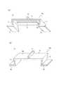
図2は、アクチュエータ10の構成例を示す斜視図である。図2(a)は、筐体20に接合される側から見た斜視図である。図2(b)は、振動対象30が接合される側から見た斜視図である。図1及び図2を参照して、アクチュエータ10の各部について説明していく。 FIG. 2 is a perspective view illustrating a configuration example of the
圧電素子11は、例えば長方形状である。圧電素子11は、印加される電圧信号に応じて長手方向に種々のパターンで伸縮変位する。圧電素子11は、圧電フィルムであってもよいし、圧電セラミックであってもよい。圧電セラミックは、圧電フィルムよりも、より大きい振動エネルギーを有する振動を発生させることができる。 The
振動板12は、所定の厚みを有する長方形の板状の部材である。振動板12は、例えば、弾性を有する薄板である。振動板12は、金属、樹脂、又は、金属及び樹脂等の複合材料等を含んで構成される。振動板12は、金属薄板(シム板ともいう)であってもよい。以下、振動板12において筐体20の側に対向する面を第1の面12aという。また、振動板12において振動対象30の側に対向する面を第2の面12bという。 The
振動板12の第1の面12aには、圧電素子11が設けられる。圧電素子11は、圧電素子11の長手方向が振動板12の長手方向と一致するように設けられる。振動板12の第2の面12bには、保持部15が設けられる。圧電素子11及び保持部15はそれぞれ、接着等の方法で振動板12に接合される。 A
振動板12の第1の面12aに圧電素子11が設けられる構造は、いわゆるモノモルフである。モノモルフにおいては、圧電素子11の伸縮変位が、振動板12の屈曲振動を引き起こす。振動板12の一方の端部のみが筐体20に支持されている場合には、振動板12の他方の端部における第1の面12aの法線方向の振幅が最大になるように振動する。振動板12の両端が筐体20に支持されている場合には、振動板12の中央付近における第1の面12aの法線方向の振幅が最大になるように振動する。 The structure in which the
振動板12の長手方向の両端にはそれぞれ、支持部13が設けられる。支持部13は、圧電素子11の変位に応じて振動板12が振動しても筐体20に衝突しないように圧電素子11と筐体20との間のクリアランスを保つ。支持部13は、振動板12と同様に、例えば弾性を有する薄板である。支持部13は、振動板12と同一の材料により構成されていてもよいし、異なる材料により構成されていてもよい。上述の通り、振動板12の両端が支持されている場合、圧電素子11の変位に応じて、振動板12の中央付近における振幅が最大になるように振動する。
支持部13の一方の端部は、振動板12に接続される。支持部13の他方の端部は、固定部14に接続される。固定部14は、例えば、ねじ止め又は接着等により筐体20に固定される。固定部14は、例えば振動板12と同様に、弾性を有する薄板である。固定部14は、振動板12と同一の材料により構成されていてもよいし、異なる材料により構成されていてもよい。 One end of the
本実施形態に係るアクチュエータ10において、振動板12と支持部13と固定部14とは、一体成型されている。すなわち、振動板12と支持部13と固定部14とは、同一の材料により構成されている。振動板12と支持部13と固定部14との一体となった部材は、例えば、一枚の金属の薄板を板金加工により折り曲げることにより一体成型されてもよい。なお、振動板12と支持部13と固定部14とは、それぞれ個別の部品が溶接されて一体に成型されてもよい。また、振動板12と支持部13と固定部14とは、樹脂の一体成型によって作られてもよい。 In the
保持部15は、振動対象30を保持する。保持部15は、例えば金属により構成される。保持部15は、金属の他、ゴム材料等の他の材料により構成されていてもよい。保持部15は、振動板12の第2の面12bに設けられる。保持部15は、例えば接着等の方法を用いて振動板12に接合される。保持部15は、第2の面12bの中央付近に設けられる。ただし、保持部15が設けられる位置は中央付近に限られない。保持部15は、振動板12の最大の振幅となる部分に設けられてもよい。保持部15には、例えば接着等の方法を用いて振動対象30が接合される。 The holding
保持部15は、ゴム材料により構成される場合、振動板12の振動が振動対象30に効率よく伝達されるように、振動板12の振動方向、つまり第1の面12aの法線方向に大きい弾性係数を有していてもよい。一方で保持部15は、振動板12の第1の面12aに平行な方向に小さい弾性係数を有していてもよい。このようにすることで、外力による触感呈示装置1の破損の可能性を低減できる。弾性係数は、部材にかかる外力と部材の変位量との関係を示す定数であり、変位量と弾性係数との積が外力となる。つまり同じ外力に対する変位量は、弾性係数が小さいほど大きくなる。 When the holding
本実施形態において、以下、一体成型された振動板12、支持部13及び固定部14と、保持部15とにより形成される部材全体を、アクチュエータ10のフレーム10aともいう。 In the present embodiment, hereinafter, the entire member formed by the integrally molded
筐体20には、固定部14においてアクチュエータ10が接合される。筐体20は、アクチュエータ10と比較して質量が大きく、剛性も高い。よって本実施形態において、筐体20は剛体とみなされる。 The
振動対象30は、例えば機器に備えられるタッチセンサ50(図3参照)又はスイッチ等であってよい。振動対象30には、保持部15においてアクチュエータ10が接合される。上述のように、筐体20が剛体とみなされる場合、アクチュエータ10が発生する振動は、主に振動対象30に伝達される。よって振動対象30は、タッチしたユーザに触感を呈示することができる。 The
[触感呈示装置の動作例]
図3は、本実施形態に係る触感呈示装置1の機能ブロックの一例である。図3に示されるように、触感呈示装置1は、上述したアクチュエータ10と、コントローラ40とを備える。コントローラ40は、アプリケーションソフトウェアを実行可能なプロセッサまたはマイクロコンピュータ等により構成することができる。コントローラ40は、必要に応じて各種情報を記憶することができるメモリ等によって構成される記憶部等も適宜含みうる。[Operation example of tactile sensation presentation device]
FIG. 3 is an example of functional blocks of the tactile
図3に示されるように、コントローラ40は、アクチュエータ10に接続される。コントローラ40は、アクチュエータ10に駆動信号を出力する。駆動信号は、アクチュエータ10の圧電素子11に対して印加される電圧信号である。 As shown in FIG. 3, the
圧電素子11は、コントローラ40から取得した駆動信号に応じて、長手方向に伸縮変位する。図1及び図2に例示されるアクチュエータ10の振動板12は、圧電素子11の変位に応じて屈曲する。つまり、圧電素子11が振動板12の長手方向に縮む方向に変位した場合、振動板12は第2の面12bが凸になるように屈曲する。また、圧電素子11が振動板12の長手方向に伸びる方向に変位した場合、振動板12は第1の面12aが凸になるように屈曲する。このように、圧電素子11の変位が、振動板12の第1の面12aの法線方向の振動に変換される。 The
本実施形態においては、圧電素子11は、電圧信号の印加に応じて縮む方向にのみ変位する。この場合、振動板12は、第2の面12bが凸になるように屈曲した状態と、屈曲していない平坦な状態とを繰り返して振動する。圧電素子11の変位は、電圧信号の印加に応じて縮む方向に限られるものではない。圧電素子11は、電圧信号の印加に応じて伸びる方向に変位するように構成されてもよいし、伸びる方向及び縮む方向のいずれにも変位するように構成されてもよい。 In the present embodiment, the
このようにして、コントローラ40は、アクチュエータ10を駆動し、振動板12を振動させる。振動板12の振動は、保持部15を介して振動対象30に伝達される。そして、振動対象30にタッチしたユーザに対して触感が呈示される。 In this way, the
コントローラ40は、例えば図3に示されるように、タッチセンサ50に接続されてもよい。この場合、コントローラ40は、タッチセンサ50から取得した信号に応じて、アクチュエータ10に駆動信号を出力してもよい。タッチセンサ50は、触感呈示装置1の振動対象30であってもよい。この場合、ユーザが振動対象30にタッチしていることがタッチセンサ50により検出される。コントローラ40は、ユーザが振動対象30にタッチしているときに振動対象30を振動させる。このようにすることで、触感呈示装置1は、振動対象30にタッチしたユーザに対して触感を呈示することができる。タッチセンサ50は、触感呈示装置1の振動対象30とは別個の構成として設けられてもよい。 The
[フレームの形状]
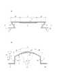
図4は、本実施形態に係るアクチュエータ10のフレーム10aの断面形状の例である。アクチュエータ10のフレーム10aは、アクチュエータ10の駆動に応じて弾性変形する。図4(a)には、アクチュエータ10が駆動されていない場合のフレーム10aの形状が示されている。また図4(b)には、アクチュエータ10が駆動されている場合のフレーム10aの形状が示されている。図4(b)において振動板12は、アクチュエータ10の駆動に応じて第2の面12bが凸となるように屈曲している。[Frame shape]
FIG. 4 is an example of a cross-sectional shape of the
図4(a)に示されるように、アクチュエータ10が駆動されていない場合、支持部13は、振動板12に接続される側の端部が固定部14に接続される側の端部よりも外側になるように設けられている。このように設けられた支持部13の状態のことを、支持部13が外側に傾いている状態ともいう。この場合、振動板12と支持部13とがなす角度は鋭角になっている。 As shown in FIG. 4A, when the
支持部13は、振動板12の法線方向と支持部13とがなす角度がαとなるように設けられている。以下、角度(α)のことを与角(α)ともいう。与角(α)は、振動板12の法線方向に対して支持部13が外側に傾いている状態の場合に正の値をとるものと定義される。与角(α)の単位はラジアンである。以降の説明に用いられる角度の単位も、特に言及がない限りラジアンである。支持部13が設けられる方向を一意に表すために、与角(α)は、−π≦α<πであるものとする。 The
支持部13の長さはHである。この場合、振動板12の端部と固定部14との距離は、Hcosαである。振動板12の端部と固定部14との距離は、振動板12の端部から固定部14を含む面に下ろした垂線の長さとして定義される。 The length of the
図4(b)に示されるように、アクチュエータ10が駆動されている場合、振動板12は屈曲している。振動板12の両端部に対する中央部の変位は、第1の面12a側から第2の面12b側へ向かう変位が正の値になるものとして、Δx(>0)である。振動板12の屈曲に応じて、支持部13の上端(振動板12に接続される側の端部)は、振動板12により、振動板12の中央部側に引っ張られる。振動板12により引っ張られた支持部13は、振動板12の法線方向と支持部13とがなす角度がβとなる。以下、角度(β)のことを変位角(β)ともいう。変位角(β)は、支持部13が外側に傾いている状態の場合に正の値をとるものと定義される。与角(α)の範囲と同様に、変位角(β)は、−π≦β<πであるものとする。アクチュエータ10の駆動状態において、支持部13の上端は、振動板12の中央部側に引っ張られるため、αとβとは、α>βを満たす。支持部13の長さは、図4(a)と同様にHである。この場合、振動板12の端部と固定部14との距離は、Hcosβである。 As shown in FIG. 4B, when the
図4(a)と図4(b)とを比較して、アクチュエータ10の駆動による振動板12の端部と固定部14との距離の変化(Δy)は、以下の式(1)により算出される。
Δy=H(cosβ−cosα) (1)
ここで、α>β>0、H>0であるから、Δy>0である。Comparing FIG. 4A and FIG. 4B, the change (Δy) in the distance between the end portion of the
Δy = H (cos β−cos α) (1)
Here, since α>β> 0 and H> 0, Δy> 0.
振動対象30に対して伝達されるアクチュエータ10の変位は、振動板12の中央部の変位(Δx)と、振動板12の端部と固定部14との距離の変化(Δy)との和である。Δy>0であるから、支持部13と振動板12の法線方向とがなす角度が変化しない場合(Δy=0)と比較して、振動対象30に対して伝達されるアクチュエータ10の変位を大きくすることができる。 The displacement of the
<比較例>
図5は、比較例に係るアクチュエータ10のフレーム10bの断面形状である。フレーム10bは、図1等に示されるフレーム10aと同様に、一体成型された振動板12、支持部13及び固定部14と、保持部15とにより構成される部材である。フレーム10bは、フレーム10aとは異なる断面形状を有する。図5(a)には、アクチュエータ10が駆動されていない場合のフレーム10bの形状が示されている。図5(b)には、アクチュエータ10が駆動されている場合のフレーム10bの形状が示されている。図5(b)において振動板12は、アクチュエータ10の駆動に応じて第2の面12bが凸となるように屈曲している。<Comparative example>
FIG. 5 is a cross-sectional shape of the
図5(a)に示されるように、アクチュエータ10が駆動されていない場合、フレーム10bの支持部13は、振動板12の法線方向に沿うように位置している。つまり図5(a)において、支持部13は振動板12に直交している。支持部13の長さはHである。この場合、振動板12の端部と固定部14との距離は、支持部13の長さと同じ(H)である。 As shown in FIG. 5A, when the
図5(b)は、アクチュエータ10が駆動されている場合を示しており、この場合に、振動板12は、両端部に対して中央部が第2の面12b側にΔxだけ変位するように屈曲しているとする。図4の場合と同様に、第1の面12a側から第2の面12b側へ向かう変位を正の値として、Δx>0とする。振動板12の屈曲に応じて、支持部13の上端(振動板12に接続される側の端部)は、振動板12により、振動板12の中央部側に引っ張られる。このとき、支持部13の変位角は、β(上述の定義によればβ<0)となっている。支持部13の長さは、図4(a)と同様にHである。この場合、振動板12の端部と固定部14との距離は、Hcosβである。 FIG. 5B shows a case where the
図5(a)と図5(b)とを比較して、アクチュエータ10の駆動による振動板12の端部と固定部14との距離の変化(Δy)は、以下の式(2)により算出される。
Δy=H(cosβ−1) (2)
ここで、cosβ<1、H>0であるから、Δy<0である。5A and 5B, the change (Δy) in the distance between the end of the
Δy = H (cos β-1) (2)
Here, since cos β <1, H> 0, Δy <0.
振動対象30に対して伝達されるアクチュエータ10の変位は、振動板12の中央部の変位(Δx)と、振動板12の端部と固定部14との距離の変化(Δy)との和である。Δy<0であるから、上述の本実施形態に係るフレーム10aの断面形状の例(Δy>0)と比較して、振動対象30に対して伝達されるアクチュエータ10の変位は小さくなっている。また、支持部13と振動板12の法線方向とがなす角度が変化しない場合(Δy=0)と比較しても、振動対象30に対して伝達されるアクチュエータ10の変位は小さくなっている。 The displacement of the
このように、本実施形態に係るフレーム10aの断面形状は、支持部13が与角(α)を有している。言い換えると、振動板12と支持部13とがなす角度が鋭角である。比較例に係るフレーム10bの断面形状のように、振動板12と支持部13とがなす角度が直角である場合、振動対象30に対して伝達されるアクチュエータ10の変位が大きくならない。また説明は省略するが、振動板12と支持部13とがなす角度が鈍角である場合も、振動対象30に対して伝達されるアクチュエータ10の変位が大きくならないことは明らかである。そのため、本実施形態に係るフレーム10aによれば、振動対象30に対して伝達されるアクチュエータ10の変位をより大きくできる。 Thus, as for the cross-sectional shape of the
次に、本実施形態における圧電素子11を保護する構造について説明する。圧電素子11は、外部からの圧力により変形すると、圧電素子11に対する押圧に係る荷重(力)の大きさ、又は荷重(力)の大きさが変化する速さ(加速度)に応じた、電気的な特性である電圧の大きさ(電圧値)の電圧信号を出力する。圧電素子11から出力される電圧信号は、例えばアクチュエータ10が用いられる機器の制御部(コントローラ)に送信される。機器の制御部は、取得した電圧信号に応じて、機器の制御を行うことができる。 Next, a structure for protecting the
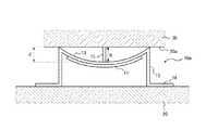
本実施形態では、例えば機器のユーザが振動対象30(タッチセンサ50)を押圧することにより、保持部15を介して振動板12の中央部が筐体20に向かって凸形状となるように湾曲する。このとき、圧電素子11も中央部が筐体20に向かって凸形状となるように湾曲する。これにより、振動対象30への押圧に応じた電圧信号が圧電素子11から出力される。 In the present embodiment, for example, when the user of the device presses the vibration target 30 (touch sensor 50), the central portion of the
ここで、ユーザが振動対象30にかける圧力が強いほど、圧電素子11の湾曲(曲率)が大きくなる。圧電素子11は、曲率が所定値以上となると、圧電素子11に亀裂が生じたり圧電素子11が折損したりする可能性がある。そのため、アクチュエータ10を、外部からの圧力に対して圧電素子11を保護する構造とすることにより、アクチュエータ10の信頼性が向上する。ここで、図6乃至図9を参照しながら、本実施形態における圧電素子11を保護する構造の詳細について説明する。 Here, as the pressure applied to the
図6は、ユーザによる振動対象30への押圧により、圧電素子11が湾曲した状態の例を示す図である。図6に示すように、ユーザによる押圧等により振動対象30が筐体20側に変位すると、保持部15が振動対象30からの圧力により、筐体20側に変位する。すると、振動板12の中央部が筐体20側に押し下げられる。そのため、振動板12及び振動板12に設けられた圧電素子11が、中央部が筐体20側に向かって凸形状となるように湾曲する。このとき、支持部13の上部が振動板12の中央部側に引っ張られ、振動板12の法線方向と支持部13とがなす角度が、押圧がかけられていない場合の与角αよりも小さくなる。そして、振動板12の中央部と、端部との高低差が、保持部15の高さと等しくなった場合、振動対象30の底面30aが振動板12の端部(つまり支持部13の上端)に接触する。これにより、支持部13は、ストッパとして機能し、振動対象30の更なる筐体20方向への変位を防止する。なお、振動板12の中央部と端部との高低差は、振動板12の2つの端部により定まる直線(平面)から中央部に下ろした垂線の長さにより定義され、図6においてdで示される。本明細書において、この高低差を振動板12の湾曲変位ともいい、特に図6に示すように振動対象30の底面30aと支持部13の上端とが接触している場合における湾曲変位を限界湾曲変位ともいう。また、保持部15の高さは、振動対象30の、保持部15によって保持される底面30aの法線方向における、保持部15の長さである。すなわち、本実施形態では、保持部15の高さは、振動板12において保持部15が取り付けられた位置(本実施形態では中央部)から振動対象30の底面30aまでの長さとして定義され、図6ではhで示される。 FIG. 6 is a diagram illustrating an example of a state in which the
振動対象30の底面30aが支持部13の上端と接触すると、振動板12はこの場合の湾曲状態から更に湾曲することはない。そのため、圧電素子11も更に湾曲することはない。従って、振動対象30の底面30aが支持部13の上端と接触した状態において、圧電素子11が破損しない程度の湾曲状態となるように、保持部15の高さが決定されていれば、圧電素子11の破損を防止することができる。 When the
ここで、本明細書において、圧電素子11が外力によって湾曲した場合における、圧電素子11の中央部から端部までの変位差を、湾曲変位という。圧電素子11の中央部から端部までの変位差は、図7に示すように、圧電素子11の2つの端部により定まる直線(平面)から中央部に下ろした垂線の長さにより定義される。湾曲変位は、図7ではDで示される。また、本明細書において、圧電素子11が破損しない最大の湾曲変位を限界湾曲変位Dmaxという。Here, in this specification, when the
本実施形態において、保持部15の高さhは、圧電素子11の限界湾曲変位Dmax未満となっている。保持部15の高さhが圧電素子11の限界湾曲変位Dmax未満であれば、つまりh<Dmaxを満たせば、圧電素子11が限界湾曲変位Dmaxに達する前に、支持部13の上端が振動対象30の底面30aに接触する。そのため、圧電素子11の湾曲変位Dが限界湾曲変位Dmaxを超えなくなり、圧電素子11を保護することができる。In the present embodiment, the height h of the holding
上述のように、振動対象30の底面30aが支持部13の上端に接触した場合、支持部13が振動対象30の更なる変位を防止するため、支持部13は振動対象30によって押圧される。支持部13は、上端が底面30aと接触した際に、支持部13が底面30aに対して垂直になるように接触すると、振動対象30からの押圧を効率的に支持しやすくなる。 As described above, when the
ここで、上端が底面30aと接触した際に支持部13が底面30aに対して垂直に接触する場合の与角α0について説明する。図8は、支持部13の与角α0について説明するための模式図である。振動板12の長手方向の長さをlとする。Here, the angle α0 in the case where the
図8(a)に示すように、振動板12が押圧されていない状態において、与角はα0である。振動対象30から振動板12が押圧され、底面30aが支持部13の上端と接触した場合、図8(b)に示すように、支持部13は、底面30aと垂直になるように接触している。このとき、底面30aと振動板12とのなす角をα1とする。ここで、振動板12の湾曲変位dは、振動板12の長手方向の長さlに対して微小であるため、α1=α0と近似できる。そのため、振動板12が湾曲した状態を示す図8(b)は、図8(c)に示す図と等価と考えることができる。As shown in FIG. 8A, in a state where the
図8(c)に示す等価図において、次の式(3)が成立する。
tanα0=d/(l/2)=2d/l (3)
従って、α0は、式(4)となる。
α0=arctan(2d/l) (4)In the equivalent diagram shown in FIG. 8C, the following equation (3) is established.
tan α0 = d / (l / 2) = 2d / l (3)
Therefore, α0 is expressed by equation (4).
α0 = arctan (2d / l) (4)
圧電素子11は、振動板12の第1の面12aに設けられているため、圧電素子11の長手方向の長さは、振動板12の長手方向の長さよりも短い。そのため、圧電素子11の湾曲変位Dは、振動板12の湾曲変位d以下となる。従って、圧電素子11の限界湾曲変位Dmaxは、振動板12の湾曲変位d以下であればよいので、式(4)において、d=Dmaxとすることにより、与角α0を、arctan(2Dmax/l)として定めればよい。Since the
なお、支持部13は、上端が底面30aと接触した際に、底面30aに対して必ずしも垂直になるように接触しなくてもよい。支持部13は、底面30aと略垂直になるように接触してもよい。ここで、略垂直とは、支持部13が座屈することなく振動対象30からの押圧を支持可能な程度である場合を含む。 In addition, the
振動対象30の底面30aが支持部13の上端に接触すると、支持部13の上端に応力が集中しやすくなる。そのため、支持部13は、応力が集中しやすい上端に、応力を分散又は吸収可能な構造を有していてもよい。 When the
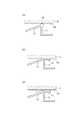
図9は、支持部13の上端の構造の例である。例えば、支持部13の上端は、図9(a)に示すように、断面視において曲面を有する構造となっていてもよい。この場合、支持部13の曲面は、支持面13bにおいて底面30aを支持する。また、例えば支持部13の上端は、上端から振動板12とは反対側に、底面30aと接触した場合に底面30aと接触して底面30aを支持する支持面13bを備えていてもよい。上記図8を参照して説明したように上端が底面30aと接触した際に支持部13が底面30aに対して垂直に接触する場合、支持面13bは、図9(b)に示すように、支持部13に対して直交するように設けられている。また、支持面13bは、図9(c)に示すように、底面30aと接触する面上に、緩衝材17を有していてもよい。支持部13がこのような構造を有することにより、底面30aとの接触に際して上端にかかる応力を分散又は吸収することができる。 FIG. 9 is an example of the structure of the upper end of the
このように、本実施形態に係るフレーム10aにおいて、保持部15の高さが、圧電素子11の限界湾曲変位Dmax未満となっている。そのため、保持部15を介して振動対象30から圧電素子11に圧力がかかっても、支持部13が上端において振動対象30を支持するので、圧電素子11は限界湾曲変位Dmax以上に湾曲しない。そのため、本実施形態に係る触感呈示装置1によれば圧電素子11を保護しやすくなる。Thus, in the
(第2実施形態)
第1実施形態では、振動板12と支持部13と固定部14とが同一の材料で一体として成型されていた。第2実施形態では、振動板12及び固定部14の材料と支持部13の材料とが異なる構成について説明する。図10は、第2実施形態に係る触感呈示装置1の構成例を示す要部断面図である。以下、第1実施形態と同一の点については、適宜説明を省略し、主に異なる点について説明する。(Second Embodiment)
In 1st Embodiment, the
本実施形態において、振動板12及び固定部14は、第1実施形態と同様に、例えば弾性を有する薄板等である。振動板12の材料と固定部14の材料とは同一であってもよいし、異なってもよい。一方で、支持部13は、例えば硬化型樹脂等により構成されるピラーであり、振動板12の法線方向の弾性係数が大きい部材である。支持部13は、金属等の他の材料により構成されてもよい。支持部13は、振動板12との接合部及び固定部14との接合部において、弾性変形するように構成される。よって支持部13は、傾斜するように動くことができる。 In the present embodiment, the
本実施形態において、振動板12と支持部13とは異なる材料間で一体成型される。例えば、振動板12と支持部13とは溶接して一体に成型されてもよい。あるいは、金属の振動板12の周りに支持部13となる樹脂を成型することにより、振動板12と支持部13とが一体成型されてもよい。あるいは、金属の振動板12に嵌合部を設け、樹脂により構成される支持部13と嵌合することにより、振動板12と支持部13とが一体成型されてもよい。あるいは、金属の振動板12の表面にプライマーを塗布した接合面を設け、当該接合面に樹脂を成型することにより、振動板12と支持部13とが一体成型されてもよい。あるいは、金属の振動板12の表面に微細加工を施した接合面を設け、当該接合面に樹脂を成型することにより、振動板12と支持部13とが一体成型されてもよい。 In the present embodiment, the
本実施形態に係るアクチュエータ10によれば、材料が互いに異なる振動板12と支持部13とが一体成型される。この場合、振動板12と支持部13とが別個の部品として構成される場合と比較して、圧電素子11の変位に応じて発生する振動板12の振動の減衰が支持部13によって低減されつつ、部品点数及び組み立て工数が削減される。本実施形態に係るアクチュエータ10によれば、振動板12と支持部13との間に接着剤を用いないことにより、平均故障間隔(MTBF)が延びたり、組み立て時の歩留まりが向上したりする。 According to the
第2実施形態に係るアクチュエータ10は、第1実施形態と同様に、振動板12と支持部13とがなす角度が鋭角である。そのため、本実施形態に係るアクチュエータ10によれば、振動板12と支持部13とがなす角度が鋭角でない場合と比較して、振動対象30に対して伝達されるアクチュエータ10の変位をより大きくできる。 In the
(他の実施形態)
図11は、振動板12と支持部13との接合部の断面形状の例である。図11(a)は、接合部の内側(振動板12の第1の面12aに連結する側)において切込み16が設けられている断面形状の例を示す。図11(b)は、接合部の外側(振動板12の第2の面12bに連結する側)において切込み16が設けられている断面形状の例である。図11(c)は、内側にも外側にも切込み16が設けられていない比較例である。(Other embodiments)
FIG. 11 is an example of a cross-sectional shape of a joint portion between the
図11(a)及び図11(b)に示される振動板12と支持部13との接合部は、図11(c)に示される例と比較して、切込み16が設けられているために屈曲しやすい。よって、支持部13の上部が振動板12の中央部側に引っ張られやすくなり、アクチュエータ10の駆動時の振動板12の屈曲が妨げられにくくなる。 Compared with the example shown in FIG. 11C, the joint portion between the
図11(a)及び図11(b)に示される切込み16は、支持部13と固定部14との接合部に設けられてもよい。このようにすることで、支持部13の与角(α)と変位角(β)との差がより大きくなりうる。 The
図12は、リブ13aを備える支持部13の例である。図12(a)は、アクチュエータ10のフレームの断面形状の例を示す。図12(b)は、図12(a)のA−A断面図である。支持部13が図12(b)に示されるようなリブ13aを有することにより、振動板12の法線方向に対する支持部13の剛性が高められる。つまり、アクチュエータ10が振動対象30に加える力の反力として支持部13に加わる力による支持部13の変形量を抑制できる。このようにすることで、アクチュエータ10が発生する振動は、支持部13に吸収されにくくなる。よってアクチュエータ10が発生する振動は、振動対象30に対してより効率よく伝達される。 FIG. 12 is an example of the
また、支持部13は、振動板12の端部が圧電素子11の伸縮変位に応じて振動板12の法線方向よりも長手方向に大きく変位するように、構成されてもよい。このように、振動板12の端部の振動板12の法線方向への変位が小さくなるように支持部13が構成される場合、振動板12の振動が振動対象30に効率よく伝達される。振動板12の端部の振動板12の長手方向への変位が大きくなるように支持部13が構成される場合、振動板12の振動の減衰が低減される。 Further, the
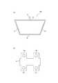
図13は、固定部14を内側に曲げて両側の固定部14を接続したフレームの例である。図13(a)は、フレームの断面形状を示している。図13(b)は、フレームの平面図である。図13(a)によれば、固定部14が接続されることにより、フレームの断面形状が台形の枠の形状となる。このようにすることで、固定部14が分離して形成される場合と比較して、フレームの強度が増す。また図13(b)によれば、固定部14の横にねじ止め用の穴14aが設けられており、固定部14の筐体20へのねじ止めが容易になっている。 FIG. 13 is an example of a frame in which the fixing
(変位の算出例)
図14は、アクチュエータ10の駆動時の各部の寸法の一例を示す図である。ここで、図14を用いて、アクチュエータ10の駆動時における振動板12の中央部の変位の算出例について説明する。なお、図14では、保持部15の記載を省略している。(Displacement calculation example)
FIG. 14 is a diagram illustrating an example of dimensions of the respective parts when the
図14(a)は、アクチュエータ10が駆動されていない場合の各部の寸法の一例である。圧電素子11の長手方向の寸法はLである。圧電素子11は、振動板12の両端からそれぞれ寸法(M)をあけて設けられている。振動板12の長手方向の寸法は、L+2Mである。支持部13の長さはHである。支持部13と振動板12の法線方向とがなす角(与角)はαである。支持部13の、固定部14に連結する側の端部は、固定部14により固定される。支持部13は、当該端部を中心として揺動可能である。 FIG. 14A is an example of the dimensions of each part when the
図14(b)は、アクチュエータ10の駆動時の各部の寸法の一例である。圧電素子11が縮むことにより、振動板12は、第2の面12b(図1参照)が凸になるように屈曲している。図14(b)において、アクチュエータ10が駆動されていない場合の振動板12及び支持部13の形状は、二点鎖線で示されている。振動板12の端部(支持部13との接合部)に対する中央部の変位(Δx)は、以下の式(5)により算出される。
Δx=Msinθ+ρ(1−cosθ) (5)
ここでρは、振動板12が屈曲する際の曲率半径である。θは、振動板12の端部において、屈曲していない状態と屈曲した状態との間の角度の差である。振動板12の屈曲部分の内角、つまり、屈曲部分を円弧とする扇形の内角は、2θと表される。曲率半径(ρ)及び内角(2θ)は、圧電素子11の変位量、又は、圧電素子11と振動板12との厚みの比等によって定められる値である。FIG. 14B is an example of dimensions of each part when the
Δx = Msin θ + ρ (1−cos θ) (5)
Here, ρ is a radius of curvature when the
曲率半径(ρ)又は屈曲部分の内角(2θ)が既知である場合、支持部13の変位角(β)は、以下の式(6)を用いて算出されうる。
β=α−M(1−cosθ)/H (6)
ここで、式(6)では、α、β、θが微小量であるとみなして、三角関数のテイラー展開に基づく近似を用いている。つまり、sinα≒α、sinβ≒β、及びsinθ≒θとしている。また、sinθ≒L/2ρとしている。When the curvature radius (ρ) or the internal angle (2θ) of the bent portion is known, the displacement angle (β) of the
β = α-M (1-cos θ) / H (6)
Here, in Expression (6), α, β, and θ are regarded as minute amounts, and approximation based on the Taylor expansion of a trigonometric function is used. That is, sin α≈α, sin β≈β, and sin θ≈θ. Further, sin θ≈L / 2ρ.
支持部13が振動板12の法線方向に平行になる場合、曲率半径(ρ)及び内角(2θ)に応じた支持部13の変位角(β)が0となる。式(6)においてβ=0の場合、与角(α)は、以下の式(7)の関係を満たす。
α=M(1−cosθ)/H (7)When the
α = M (1-cos θ) / H (7)
図14(b)において、支持部13は、振動板12の屈曲に応じて、アクチュエータ10が駆動されていない場合の振動板12の法線方向に平行になっている。この場合、振動板12の端部と固定部14との距離の変化(Δy)は、以下の式(8)により算出される。
Δy=H(1−cosθ) (8)In FIG. 14B, the
Δy = H (1-cos θ) (8)
振動板12の中央部の変位(Δz)は、ΔxとΔyとの和である。よって図14(b)に示される振動板12の中央部の変位(Δz)は、式(5)及び式(8)に基づく以下の式(9)を用いて算出される。
Δz=Msinθ+ρ(1−cosθ)+H(1−cosθ) (9)The displacement (Δz) at the center of the
Δz = Msin θ + ρ (1−cos θ) + H (1−cos θ) (9)
上述の式(1)によれば、与角(α)と変位角(β)とがcosα<cosβを満たす場合、Δy>0となる。ここで、実施形態1等に係るアクチュエータ10においては、α>βとなる。よって、β≧0であれば、Δy>0である。以上のことから、Δy>0となるための与角(α)に係る十分条件は、以下の式(10)により表される。
α≧M(1−cosθ)/H (10)According to the above equation (1), Δy> 0 when the angle of incidence (α) and the displacement angle (β) satisfy cos α <cos β. Here, in the
α ≧ M (1-cos θ) / H (10)
したがって式(10)を満たすように、支持部13の与角(α)を適宜設定すれば、振動板12の中央部の振幅を大きくすることができる。 Therefore, the amplitude of the central portion of the
本発明に係る実施形態について諸図面や実施例に基づき説明してきたが、当業者であれば本開示に基づき種々の変形や修正を行うことが容易であることに注意されたい。従って、これらの変形や修正は本発明の範囲に含まれることに留意されたい。 Although the embodiments according to the present invention have been described based on the drawings and examples, it should be noted that those skilled in the art can easily make various modifications and corrections based on the present disclosure. Therefore, it should be noted that these variations and modifications are included in the scope of the present invention.
1 触感呈示装置
10 アクチュエータ
10a、10b フレーム
11 圧電素子
12 振動板
12a 第1の面
12b 第2の面
13 支持部
13a リブ
13b 支持面
14 固定部
14a 穴
15 保持部
16 切込み
17 緩衝材
20 筐体
30 振動対象
30a 底面
40 コントローラ
50 タッチセンサDESCRIPTION OF
Claims (8)
Translated fromJapanese前記圧電素子が接合され、前記圧電素子の伸縮変位に応じて振動対象を振動させる振動板と、
前記振動板に接合され、前記振動対象を保持する保持部と
を備え、
前記保持部の高さは、外力によって前記圧電素子が破損しない最大の湾曲変位未満である、アクチュエータ。A piezoelectric element;
A diaphragm that is bonded to the piezoelectric element and vibrates a vibration target in accordance with expansion and contraction displacement of the piezoelectric element;
A holding part that is joined to the diaphragm and holds the vibration object;
The height of the holding portion is an actuator that is less than a maximum bending displacement at which the piezoelectric element is not damaged by an external force.
前記振動板と前記支持部とが一体成型されている、請求項1に記載のアクチュエータA support portion for supporting the diaphragm on a fixed portion;
The actuator according to claim 1, wherein the diaphragm and the support portion are integrally molded.
前記保持部に保持され、前記振動板の振動が伝達されてユーザに対して触感を呈示する振動対象と
を備え、
前記保持部の高さは、外力によって前記圧電素子が破損しない最大の湾曲変位未満である、触感呈示装置。An actuator comprising a piezoelectric element, a diaphragm to which the piezoelectric element is bonded and vibrates according to expansion and contraction displacement of the piezoelectric element, and a holding unit bonded to the diaphragm;
A vibration object that is held by the holding unit and transmits vibrations of the diaphragm and presents a tactile sensation to the user;
The height of the said holding | maintenance part is a tactile sensation presentation apparatus which is less than the largest bending displacement in which the said piezoelectric element is not damaged by external force.
Priority Applications (4)
| Application Number | Priority Date | Filing Date | Title |
|---|---|---|---|
| JP2016062430AJP6955843B2 (en) | 2016-03-25 | 2016-03-25 | Actuator and tactile presentation device |
| US16/084,640US11411167B2 (en) | 2016-03-25 | 2017-03-10 | Actuator and tactile sensation providing apparatus |
| EP17769983.2AEP3435536B1 (en) | 2016-03-25 | 2017-03-10 | Actuator and tactile sensation presentation device |
| PCT/JP2017/009789WO2017163939A1 (en) | 2016-03-25 | 2017-03-10 | Actuator, and tactile sensation presentation device |
Applications Claiming Priority (1)
| Application Number | Priority Date | Filing Date | Title |
|---|---|---|---|
| JP2016062430AJP6955843B2 (en) | 2016-03-25 | 2016-03-25 | Actuator and tactile presentation device |
Publications (2)
| Publication Number | Publication Date |
|---|---|
| JP2017175874Atrue JP2017175874A (en) | 2017-09-28 |
| JP6955843B2 JP6955843B2 (en) | 2021-10-27 |
Family
ID=59899502
Family Applications (1)
| Application Number | Title | Priority Date | Filing Date |
|---|---|---|---|
| JP2016062430AActiveJP6955843B2 (en) | 2016-03-25 | 2016-03-25 | Actuator and tactile presentation device |
Country Status (4)
| Country | Link |
|---|---|
| US (1) | US11411167B2 (en) |
| EP (1) | EP3435536B1 (en) |
| JP (1) | JP6955843B2 (en) |
| WO (1) | WO2017163939A1 (en) |
Cited By (9)
| Publication number | Priority date | Publication date | Assignee | Title |
|---|---|---|---|---|
| WO2019225333A1 (en) | 2018-05-23 | 2019-11-28 | 京セラ株式会社 | Structure and tactile sensation-providing device |
| EP3575927A1 (en) | 2018-05-28 | 2019-12-04 | Kyocera Corporation | Unit and tactile sensation providing apparatus |
| WO2019230248A1 (en)* | 2018-05-31 | 2019-12-05 | Tdk株式会社 | Vibration unit, driving apparatus, and driving method |
| WO2019230367A1 (en) | 2018-05-28 | 2019-12-05 | 京セラ株式会社 | Actuator and tactile sensation presentation device |
| JP2019212265A (en)* | 2018-05-31 | 2019-12-12 | Tdk株式会社 | Vibration unit, driving device, and method for driving |
| WO2020105495A1 (en) | 2018-11-22 | 2020-05-28 | 京セラ株式会社 | Actuator and tactile presentation device |
| EP3917688A1 (en)* | 2018-12-31 | 2021-12-08 | Hap2u | Piezoelectric actuators with increased deformation |
| KR20210152599A (en)* | 2020-06-08 | 2021-12-16 | 한국전자통신연구원 | Piezoelectric device |
| JP2024542535A (en)* | 2021-11-24 | 2024-11-15 | テーデーカー エレクトロニクス アーゲー | Haptic Devices |
Families Citing this family (3)
| Publication number | Priority date | Publication date | Assignee | Title |
|---|---|---|---|---|
| JP6584360B2 (en)* | 2016-04-22 | 2019-10-02 | アルパイン株式会社 | Operating device having feedback mechanism |
| TWI637303B (en)* | 2017-10-11 | 2018-10-01 | 聯陽半導體股份有限公司 | Touch device and method for operating a touch device |
| DE102020102516B3 (en)* | 2020-01-31 | 2021-02-18 | Kyocera Corporation | Tactile vibration generator |
Citations (7)
| Publication number | Priority date | Publication date | Assignee | Title |
|---|---|---|---|---|
| JPH01177880A (en)* | 1988-01-08 | 1989-07-14 | Olympus Optical Co Ltd | Ultrasonic linear motor |
| WO2007026736A1 (en)* | 2005-08-31 | 2007-03-08 | Nec Corporation | Piezoelectric actuator, acoustic element, and electronic device |
| WO2009063610A1 (en)* | 2007-11-13 | 2009-05-22 | Kohei Hayamizu | Power generation unit |
| EP2184664A1 (en)* | 2008-10-30 | 2010-05-12 | Research In Motion Limited | Portable electronic device including touch-sensitive input device and method of controlling same |
| JP2010152888A (en)* | 2008-12-23 | 2010-07-08 | Research In Motion Ltd | Portable electronic device and method of control |
| JP2010200607A (en)* | 2010-03-26 | 2010-09-09 | Kohei Hayamizu | Generator |
| JP2014230482A (en)* | 2013-05-20 | 2014-12-08 | イノチップス テクノロジー カンパニー リミテッド | Piezoelectric vibrating device |
Family Cites Families (5)
| Publication number | Priority date | Publication date | Assignee | Title |
|---|---|---|---|---|
| US9046947B2 (en) | 2010-10-21 | 2015-06-02 | Kyocera Corporation | Touch panel apparatus with piezoelectric element |
| KR101454071B1 (en)* | 2012-05-08 | 2014-10-27 | 삼성전기주식회사 | Piezo vibration module |
| EP2662909A1 (en)* | 2012-05-08 | 2013-11-13 | Aito B.V. | A piezoelectric device |
| WO2014098429A1 (en)* | 2012-12-17 | 2014-06-26 | (주) 테라다인 | Piezo actuator |
| JP5781495B2 (en)* | 2012-12-28 | 2015-09-24 | 京セラドキュメントソリューションズ株式会社 | Touch panel device |
- 2016
- 2016-03-25JPJP2016062430Apatent/JP6955843B2/enactiveActive
- 2017
- 2017-03-10WOPCT/JP2017/009789patent/WO2017163939A1/ennot_activeCeased
- 2017-03-10EPEP17769983.2Apatent/EP3435536B1/enactiveActive
- 2017-03-10USUS16/084,640patent/US11411167B2/enactiveActive
Patent Citations (7)
| Publication number | Priority date | Publication date | Assignee | Title |
|---|---|---|---|---|
| JPH01177880A (en)* | 1988-01-08 | 1989-07-14 | Olympus Optical Co Ltd | Ultrasonic linear motor |
| WO2007026736A1 (en)* | 2005-08-31 | 2007-03-08 | Nec Corporation | Piezoelectric actuator, acoustic element, and electronic device |
| WO2009063610A1 (en)* | 2007-11-13 | 2009-05-22 | Kohei Hayamizu | Power generation unit |
| EP2184664A1 (en)* | 2008-10-30 | 2010-05-12 | Research In Motion Limited | Portable electronic device including touch-sensitive input device and method of controlling same |
| JP2010152888A (en)* | 2008-12-23 | 2010-07-08 | Research In Motion Ltd | Portable electronic device and method of control |
| JP2010200607A (en)* | 2010-03-26 | 2010-09-09 | Kohei Hayamizu | Generator |
| JP2014230482A (en)* | 2013-05-20 | 2014-12-08 | イノチップス テクノロジー カンパニー リミテッド | Piezoelectric vibrating device |
Cited By (20)
| Publication number | Priority date | Publication date | Assignee | Title |
|---|---|---|---|---|
| US11599195B2 (en) | 2018-05-23 | 2023-03-07 | Kyocera Corporation | Structure and tactile sensation providing apparatus |
| WO2019225333A1 (en) | 2018-05-23 | 2019-11-28 | 京セラ株式会社 | Structure and tactile sensation-providing device |
| US11620882B2 (en) | 2018-05-28 | 2023-04-04 | Kyocera Corporation | Actuator and tactile sensation providing apparatus |
| EP3575927A1 (en) | 2018-05-28 | 2019-12-04 | Kyocera Corporation | Unit and tactile sensation providing apparatus |
| KR20190135395A (en) | 2018-05-28 | 2019-12-06 | 교세라 가부시키가이샤 | Unit and tactile sensation providing apparatus |
| WO2019230367A1 (en) | 2018-05-28 | 2019-12-05 | 京セラ株式会社 | Actuator and tactile sensation presentation device |
| US11318498B2 (en) | 2018-05-28 | 2022-05-03 | Kyocera Corporation | Unit and tactile sensation providing apparatus |
| EP3805905A4 (en)* | 2018-05-28 | 2022-03-09 | Kyocera Corporation | ACTUATOR AND DEVICE FOR REPRESENTING TACTILE SENSATION |
| JP7077898B2 (en) | 2018-05-31 | 2022-05-31 | Tdk株式会社 | Vibration unit, drive device and drive method |
| WO2019230248A1 (en)* | 2018-05-31 | 2019-12-05 | Tdk株式会社 | Vibration unit, driving apparatus, and driving method |
| JP2019212265A (en)* | 2018-05-31 | 2019-12-12 | Tdk株式会社 | Vibration unit, driving device, and method for driving |
| WO2020105495A1 (en) | 2018-11-22 | 2020-05-28 | 京セラ株式会社 | Actuator and tactile presentation device |
| US11605272B2 (en) | 2018-11-22 | 2023-03-14 | Kyocera Corporation | Actuator and tactile sensation providing apparatus |
| JP2022516897A (en)* | 2018-12-31 | 2022-03-03 | アップ2ユー | Amplified deformation type piezoelectric actuator |
| EP3917688A1 (en)* | 2018-12-31 | 2021-12-08 | Hap2u | Piezoelectric actuators with increased deformation |
| JP2024095731A (en)* | 2018-12-31 | 2024-07-10 | アップ2ユー | Amplified deformation type piezoelectric actuator |
| JP7654547B2 (en) | 2018-12-31 | 2025-04-01 | アップ2ユー | Amplified deformation type piezoelectric actuator |
| KR20210152599A (en)* | 2020-06-08 | 2021-12-16 | 한국전자통신연구원 | Piezoelectric device |
| KR102576730B1 (en)* | 2020-06-08 | 2023-09-12 | 한국전자통신연구원 | Piezoelectric device |
| JP2024542535A (en)* | 2021-11-24 | 2024-11-15 | テーデーカー エレクトロニクス アーゲー | Haptic Devices |
Also Published As
| Publication number | Publication date |
|---|---|
| EP3435536A1 (en) | 2019-01-30 |
| US20190074425A1 (en) | 2019-03-07 |
| EP3435536A4 (en) | 2019-11-20 |
| WO2017163939A1 (en) | 2017-09-28 |
| EP3435536B1 (en) | 2023-06-21 |
| US11411167B2 (en) | 2022-08-09 |
| JP6955843B2 (en) | 2021-10-27 |
Similar Documents
| Publication | Publication Date | Title |
|---|---|---|
| JP6955843B2 (en) | Actuator and tactile presentation device | |
| US11527704B2 (en) | Actuator and tactile sensation providing apparatus | |
| WO2017163945A1 (en) | Actuator, and tactile sensation presentation device | |
| US11877515B2 (en) | Actuator and tactile sensation providing apparatus | |
| US10969868B2 (en) | Tactile sensation providing apparatus | |
| JP6811297B2 (en) | Tactile presentation device | |
| JP7162508B2 (en) | Actuator and tactile presentation device | |
| WO2017081868A1 (en) | Tactile sensation presentation device and electronic device | |
| JP6926029B2 (en) | Structure and tactile presentation device | |
| JP2019102317A (en) | Switch device |
Legal Events
| Date | Code | Title | Description |
|---|---|---|---|
| A621 | Written request for application examination | Free format text:JAPANESE INTERMEDIATE CODE: A621 Effective date:20180724 | |
| A131 | Notification of reasons for refusal | Free format text:JAPANESE INTERMEDIATE CODE: A131 Effective date:20190611 | |
| A521 | Request for written amendment filed | Free format text:JAPANESE INTERMEDIATE CODE: A523 Effective date:20190801 | |
| A131 | Notification of reasons for refusal | Free format text:JAPANESE INTERMEDIATE CODE: A131 Effective date:20191119 | |
| A521 | Request for written amendment filed | Free format text:JAPANESE INTERMEDIATE CODE: A523 Effective date:20200114 | |
| A02 | Decision of refusal | Free format text:JAPANESE INTERMEDIATE CODE: A02 Effective date:20200519 | |
| A521 | Request for written amendment filed | Free format text:JAPANESE INTERMEDIATE CODE: A523 Effective date:20200805 | |
| C60 | Trial request (containing other claim documents, opposition documents) | Free format text:JAPANESE INTERMEDIATE CODE: C60 Effective date:20200805 | |
| A911 | Transfer to examiner for re-examination before appeal (zenchi) | Free format text:JAPANESE INTERMEDIATE CODE: A911 Effective date:20200814 | |
| C21 | Notice of transfer of a case for reconsideration by examiners before appeal proceedings | Free format text:JAPANESE INTERMEDIATE CODE: C21 Effective date:20200818 | |
| A912 | Re-examination (zenchi) completed and case transferred to appeal board | Free format text:JAPANESE INTERMEDIATE CODE: A912 Effective date:20201023 | |
| C211 | Notice of termination of reconsideration by examiners before appeal proceedings | Free format text:JAPANESE INTERMEDIATE CODE: C211 Effective date:20201027 | |
| C22 | Notice of designation (change) of administrative judge | Free format text:JAPANESE INTERMEDIATE CODE: C22 Effective date:20210112 | |
| C22 | Notice of designation (change) of administrative judge | Free format text:JAPANESE INTERMEDIATE CODE: C22 Effective date:20210413 | |
| C13 | Notice of reasons for refusal | Free format text:JAPANESE INTERMEDIATE CODE: C13 Effective date:20210420 | |
| RD03 | Notification of appointment of power of attorney | Free format text:JAPANESE INTERMEDIATE CODE: A7423 Effective date:20210615 | |
| A521 | Request for written amendment filed | Free format text:JAPANESE INTERMEDIATE CODE: A523 Effective date:20210618 | |
| C302 | Record of communication | Free format text:JAPANESE INTERMEDIATE CODE: C302 Effective date:20210728 | |
| C23 | Notice of termination of proceedings | Free format text:JAPANESE INTERMEDIATE CODE: C23 Effective date:20210810 | |
| C03 | Trial/appeal decision taken | Free format text:JAPANESE INTERMEDIATE CODE: C03 Effective date:20210914 | |
| C30A | Notification sent | Free format text:JAPANESE INTERMEDIATE CODE: C3012 Effective date:20210914 | |
| A61 | First payment of annual fees (during grant procedure) | Free format text:JAPANESE INTERMEDIATE CODE: A61 Effective date:20211004 | |
| R150 | Certificate of patent or registration of utility model | Ref document number:6955843 Country of ref document:JP Free format text:JAPANESE INTERMEDIATE CODE: R150 |