JP2017175435A - Electronic apparatus - Google Patents
Electronic apparatusDownload PDFInfo
- Publication number
- JP2017175435A JP2017175435AJP2016060456AJP2016060456AJP2017175435AJP 2017175435 AJP2017175435 AJP 2017175435AJP 2016060456 AJP2016060456 AJP 2016060456AJP 2016060456 AJP2016060456 AJP 2016060456AJP 2017175435 AJP2017175435 AJP 2017175435A
- Authority
- JP
- Japan
- Prior art keywords
- antenna
- electronic device
- lens
- unit
- lens unit
- Prior art date
- Legal status (The legal status is an assumption and is not a legal conclusion. Google has not performed a legal analysis and makes no representation as to the accuracy of the status listed.)
- Pending
Links
Images


Classifications
- H—ELECTRICITY
- H01—ELECTRIC ELEMENTS
- H01Q—ANTENNAS, i.e. RADIO AERIALS
- H01Q1/00—Details of, or arrangements associated with, antennas
- H01Q1/12—Supports; Mounting means
- H01Q1/22—Supports; Mounting means by structural association with other equipment or articles
- H01Q1/2291—Supports; Mounting means by structural association with other equipment or articles used in bluetooth or WI-FI devices of Wireless Local Area Networks [WLAN]
- G—PHYSICS
- G02—OPTICS
- G02C—SPECTACLES; SUNGLASSES OR GOGGLES INSOFAR AS THEY HAVE THE SAME FEATURES AS SPECTACLES; CONTACT LENSES
- G02C11/00—Non-optical adjuncts; Attachment thereof
- G02C11/10—Electronic devices other than hearing aids
- G—PHYSICS
- G02—OPTICS
- G02C—SPECTACLES; SUNGLASSES OR GOGGLES INSOFAR AS THEY HAVE THE SAME FEATURES AS SPECTACLES; CONTACT LENSES
- G02C7/00—Optical parts
- G02C7/10—Filters, e.g. for facilitating adaptation of the eyes to the dark; Sunglasses
- H—ELECTRICITY
- H01—ELECTRIC ELEMENTS
- H01Q—ANTENNAS, i.e. RADIO AERIALS
- H01Q1/00—Details of, or arrangements associated with, antennas
- H01Q1/12—Supports; Mounting means
- H01Q1/22—Supports; Mounting means by structural association with other equipment or articles
- H01Q1/24—Supports; Mounting means by structural association with other equipment or articles with receiving set
- H01Q1/241—Supports; Mounting means by structural association with other equipment or articles with receiving set used in mobile communications, e.g. GSM
- H01Q1/242—Supports; Mounting means by structural association with other equipment or articles with receiving set used in mobile communications, e.g. GSM specially adapted for hand-held use
- H01Q1/245—Supports; Mounting means by structural association with other equipment or articles with receiving set used in mobile communications, e.g. GSM specially adapted for hand-held use with means for shaping the antenna pattern, e.g. in order to protect user against rf exposure
- H—ELECTRICITY
- H01—ELECTRIC ELEMENTS
- H01Q—ANTENNAS, i.e. RADIO AERIALS
- H01Q1/00—Details of, or arrangements associated with, antennas
- H01Q1/27—Adaptation for use in or on movable bodies
- H01Q1/273—Adaptation for carrying or wearing by persons or animals
- H—ELECTRICITY
- H01—ELECTRIC ELEMENTS
- H01Q—ANTENNAS, i.e. RADIO AERIALS
- H01Q1/00—Details of, or arrangements associated with, antennas
- H01Q1/44—Details of, or arrangements associated with, antennas using equipment having another main function to serve additionally as an antenna, e.g. means for giving an antenna an aesthetic aspect
- H—ELECTRICITY
- H01—ELECTRIC ELEMENTS
- H01Q—ANTENNAS, i.e. RADIO AERIALS
- H01Q21/00—Antenna arrays or systems
- H01Q21/30—Combinations of separate antenna units operating in different wavebands and connected to a common feeder system
Landscapes
- Physics & Mathematics (AREA)
- Health & Medical Sciences (AREA)
- Engineering & Computer Science (AREA)
- Computer Networks & Wireless Communication (AREA)
- Ophthalmology & Optometry (AREA)
- General Health & Medical Sciences (AREA)
- General Physics & Mathematics (AREA)
- Optics & Photonics (AREA)
- Acoustics & Sound (AREA)
- Otolaryngology (AREA)
- Eyeglasses (AREA)
- Aerials With Secondary Devices (AREA)
- Details Of Aerials (AREA)
- Variable-Direction Aerials And Aerial Arrays (AREA)
- Support Of Aerials (AREA)
- Transceivers (AREA)
- Transmitters (AREA)
- Radio Transmission System (AREA)
Abstract
Description
Translated fromJapanese本発明は、電子機器に関する。The present invention relates to an electronic device.
近年、ユーザの身体に装着させて使用することができるウェアラブル端末の利用が普及しつつある。ウェアラブル端末として、例えば、特許文献1から3に記載の電子機器が知られている。 In recent years, the use of wearable terminals that can be used by being worn on a user's body is becoming widespread. As wearable terminals, for example, electronic devices described in
ユーザの身体に装着させる無線通信機は、SAR(比吸収率:Specific Absorption Rate)が基準値以下であることを満たす必要がある。しかしながら、特許文献1から3に記載の電子機器では、電波を送受信する無線通信機のアンテナがユーザの頭部に近接するため、SARが増大して基準値を超える可能性がある。また、ユーザの身体に装着させる無線通信機は、ユーザの頭部による電波伝搬の妨害を受けるため無線性能の劣化を招きやすい。 The wireless communication device to be worn on the user's body needs to satisfy that the SAR (Specific Absorption Rate) is not more than a reference value. However, in the electronic devices described in
本発明の目的は、上記の問題に鑑みてなされたものであり、SARを低減させ、さらに良好な無線通信を行うことができる電子機器を提供することにある。 An object of the present invention has been made in view of the above problems, and it is an object of the present invention to provide an electronic device that can reduce SAR and perform better wireless communication.
本発明の一実施形態に係る電子機器は、ユーザの頭部に装着させて使用する電子機器であって、ユーザの目の前側に配置されるレンズ部と、前記レンズ部に形成された第1のアンテナと、前記レンズ部に形成された第2のアンテナと備え、前記第1のアンテナと前記第2のアンテナとは異なる機能のアンテナである。 An electronic apparatus according to an embodiment of the present invention is an electronic apparatus that is used by being mounted on a user's head, and includes a lens unit disposed in front of the user's eyes and a first formed on the lens unit. And the second antenna formed on the lens unit, the first antenna and the second antenna are different functioning antennas.
本発明の電子機器によれば、SARを低減させ、さらに良好な無線通信を行うことができる。 According to the electronic apparatus of the present invention, it is possible to reduce SAR and perform better wireless communication.
以下、本発明の電子機器の一実施形態について、図面を参照して説明する。 Hereinafter, an embodiment of an electronic device of the present invention will be described with reference to the drawings.
[電子機器の構成]
図1は、本発明に係る電子機器の一実施形態の構成を示す斜視図である。図1に示されるように、本実施形態の電子機器は、いわゆる眼鏡型の無線通信機の構造となっている。[Configuration of electronic equipment]
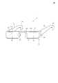
FIG. 1 is a perspective view showing a configuration of an embodiment of an electronic apparatus according to the present invention. As shown in FIG. 1, the electronic apparatus of the present embodiment has a so-called glasses-type wireless communication device structure.
電子機器1は、テンプル部10,11と、レンズ部(第1のレンズ部)12と、レンズ部(第2のレンズ部)13と、鼻あて部14,15と、ブリッジ部16と、アンテナ(第1のアンテナ)20と、アンテナ(第2のアンテナ)21と、制御回路100とを備える。なお、図1では、給電線等は図示を省略している。 The
テンプル部10,11は、ユーザが電子機器1を装着している状態(以下、適宜「ユーザ装着状態」と記載する)では、ユーザの頭部の側面に位置する。テンプル部10は、ユーザの頭部の左側面に配置され、テンプル部11は、ユーザの頭部の右側面に配置される。 The
テンプル部10は、その先端に耳掛け部10aを有する。テンプル部11は、その先端に耳掛け部11aを有する。耳掛け部10aは、ユーザ装着状態ではユーザの左の耳に掛けられる。耳掛け部11aは、ユーザ装着状態ではユーザの右の耳に掛けられる。 The
レンズ部12は、一端でテンプル部10と連結し、他端でブリッジ部16と連結する。レンズ部13は、一端でテンプル部11と連結し、他端でブリッジ部16と連結する。 The
レンズ部12は、ユーザ装着状態ではユーザの左の目の前に位置する。レンズ部13は、ユーザ装着状態ではユーザの右の目の前に位置する。リム部12aは、レンズ部12の縁を囲み、リム部13aは、レンズ部13の縁を囲む。 The
鼻あて部14は、レンズ部12のブリッジ部16側に設けられる。鼻あて部15は、レンズ部13のブリッジ部16側に設けられる。鼻あて部14は、ユーザ装着状態では、ユーザの鼻の左の側にあてられる。鼻あて部15は、ユーザ装着状態では、ユーザの鼻の右の側にあてられる。 The
ブリッジ部16は、左右のレンズ部12,13の間を連結することで、レンズ部12,13を所定の位置関係に維持する。 The bridge portion 16 connects the left and
アンテナ20は、レンズ部12のレンズ面に形成されている。アンテナ21は、レンズ部13のレンズ面に形成されている。なお、アンテナ20とアンテナ21とが、レンズ部12、レンズ部13のいずれか一方のみに形成されていてもよい。アンテナ20及びアンテナ21は、例えば、透明電極膜又は金属箔等のパターンがレンズ上に印刷されることにより形成される。本実施形態では、アンテナ20及びアンテナ21として透明電極を用いる。 The
制御回路100は、アンテナ20及びアンテナ21を用いた電波の送受信を制御する。制御回路100は、テンプル部10に配置されているが、テンプル部11やその他の箇所に配置されていてもよい。例えば、制御回路100は、リム部12a,13a、鼻あて部14,15又はレンズ部12,13の留め具(図示していないが、矢印Aの箇所に位置する)等に配置されていてもよい。 The
なお、アンテナ20の電波の送受信を制御する第1の制御回路と、アンテナ21の電波の送受信を制御する第2の制御回路との2つの制御回路を用いてもよい。 Two control circuits of a first control circuit that controls transmission / reception of radio waves from the
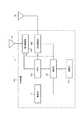
以下、制御回路100の概略構成について図2を参照して説明する。図2は、図1に示される電子機器の回路構成の機能ブロック図である。 Hereinafter, a schematic configuration of the
制御回路100は、電源部110、RF(Radio Frequency)部120、整合回路部130a,130b、制御部140、記憶部150を有する。 The
電源部110は、例えば充電可能な二次電池により構成される。電源部110は、RF部120、制御部140及び記憶部150等に電力を供給する。なお、図2に示される例では、電源部110は、図を簡単にするため制御部140との接続関係を示しているのみであるが、実際には、電源部110は、制御回路100の各要素と電気的に接続され、これら各要素に電力を供給する。また、電源部110は図2では制御回路100に含まれているとしているが、電子機器1において制御回路100とは別の場所に配置されていてもよい。 The
RF部120は、制御部140から出力された送信信号を変調し、不図示のスイッチを介してアンテナ20又はアンテナ21に出力する。また、RF部120は、アンテナ20又はアンテナ21から取得した受信信号を変調して制御部140に出力する。 The
整合回路部130aは、制御部140からの制御信号により整合回路部130a内のインピーダンスを調整することで、アンテナ20のインピーダンスと、制御回路100を構成する回路のインピーダンスとを整合させる。また、整合回路部130bは、制御部140からの制御信号により整合回路部130b内のインピーダンスを調整することで、アンテナ21のインピーダンスと、制御回路100を構成する回路のインピーダンスとを整合させる。アンテナ20及びアンテナ21のインピーダンスと制御回路100を構成する回路のインピーダンスとを整合させると、アンテナ20及びアンテナ21からの受信信号の制御回路100での反射が低減され、制御部140で処理される受信信号の強度が増加する。なお、整合回路部130a,130b内のインピーダンスは、制御部140からの制御信号によって調整可能でなくてもよく、固定であってもよい。 The
制御部140は、電子機器1全体を制御及び管理するものであり、例えばプロセッサにより構成することができる。制御部140は、記憶部150に記憶されているプログラムを読み出して実行し、様々な機能を実現させる。 The
制御部140は、RF部120から取得した受信信号を復調する。また、制御部140は、アンテナ20又はアンテナ21から送信する送信信号をRF部120に出力する。また、制御部140は、例えば、制御信号を整合回路部130a,130bに出力して整合回路部130a,130b内のインピーダンスを調整させることで、整合回路部130a,130bに、アンテナ20,21のインピーダンスと制御回路100を構成する回路のインピーダンスとを整合させる。 The
記憶部150は、制御部140の処理に必要な情報や、制御部140の各機能を実現する処理内容を記述したプログラムを記憶している。 The
次に、図1に示される電子機器1をユーザが装着した場合について図3を用いて説明する。図3は、図1に示される電子機器1をユーザが装着した場合の概念図である。なお、図3に示される例では、図面を簡略にするために、電子機器1におけるレンズ部12,13とユーザの頭部との関係を示しているのみであり、図1に示されるテンプル部10,11やリム部12a,13aなどとの関係の図示は省略している。 Next, a case where the user wears the
図3に示されるように、電子機器1をユーザ300が装着した場合、電子機器1のレンズ部12,13はユーザ300の額部分301から一定距離Lだけ離れて配置される。 As shown in FIG. 3, when the
このようにユーザの頭部に直接接触しないレンズ部12,13にアンテナ20,21を配置することで、電子機器1では、SARを低減することができる。 In this way, the SAR can be reduced in the
また、ユーザの頭部から所定距離(図3の例では距離L)離れたレンズ部12,13にアンテナ20,21を配置することで、ユーザの頭部による電波伝搬の妨害を低減させることができ、アンテナ20,21の電波の送受信に関する性能を向上させることができる。 Further, by disposing the
また、アンテナ20,21を重量が軽いアンテナパターンを印刷して形成することで、電子機器1の軽量化に寄与することができる。また、アンテナ配置用の部材を新たに設けず、レンズ部12,13にアンテナ20,21を印刷により形成しているため、電子機器1のデザイン性を良好に維持することができる。また、アンテナ20,21を、例えば透明電極膜で形成することで、電子機器1のデザイン性をさらに良好に維持することができる。 Further, by forming the
また、アンテナ20は送信用の指向性アンテナ、アンテナ21は受信用の無指向性アンテナである。すなわち、アンテナ20,21は、互いに異なる機能を有するアンテナである。アンテナ20を送信用の指向性アンテナ及びアンテナ21を受信用の無指向性アンテナとすることで、本実施形態では、送信の際は所望の方向へ指向性の良い送信が行えると共に、受信の際は指向性に左右されない効率の良い待ち受け状態とする事が出来る。 The
アンテナ20,21の互いに異なる機能は、例えば、電子機器1の用途に応じて設定してもよい。 Different functions of the
また、例えば、電子機器1をMIMO又はダイバーシチによる通信方式で使用する場合、アンテナ20をメインアンテナ、アンテナ21をサブアンテナにしてもよい。レンズ部12のアンテナ20をメインアンテナとし、レンズ部13のアンテナ21をサブアンテナとすると、レンズ部12,13が互いに離れているため、メインアンテナとサブアンテナとのアイソレーションを十分に確保できるようになる。もちろん、アンテナ21をメインアンテナ、アンテナ20をサブアンテナにしてもよい。 Further, for example, when the
また、例えば、電子機器1を複数の通信方式において使用する場合、アンテナ20をWAN(Wide Area Network)用アンテナ、アンテナ21をWLAN(Wireless Local Area Network)用アンテナとすることができる。レンズ部12のアンテナ20をWAN用アンテナとし、レンズ部13のアンテナ21をWLAN用アンテナとすると、レンズ部12,13が互いに離れているため、アンテナ20,21間の干渉を低減させることができる。なお、アンテナ21をWAN(Wide Area Network)用アンテナ、アンテナ20をWLAN(Wireless Local Area Network)用アンテナとしてもよい。 Further, for example, when the
このように、電子機器1では、互いに異なる機能を有するアンテナ20,21を備えることで、例えばMIMO又はダイバーシチによる通信方式等といった、多様な用途に応用することができる。 As described above, the
なお、レンズ部12,13は、レンズが着色されたサングラス用のレンズを含んでいてもよい。レンズ部12,13をサングラス用のレンズとすることで、アンテナ20,21がより目立たなくなるため、電子機器1のデザイン性をより良好に維持することができる。 In addition, the
また、アンテナ20,21は、任意の形状であってよく、さらに、レンズ部12,13の任意の箇所に形成されていてもよい。例えば、アンテナ20,21をそれぞれレンズ部12,13のレンズの外周部に形成することで、視野を良好に維持することができる。 The
また、上記では、アンテナ20,21は、互いに異なる機能を有するものとしたが、アンテナ20,21は、互いに同じ機能を有していてもよい。 In the above description, the
以上のように、本発明の一実施形態に係る電子機器1では、ユーザの左右の目の前に位置するレンズ部12,13を備え、レンズ部12のレンズ面には、アンテナ20が印刷され、レンズ部13のレンズ面には、アンテナ21が印刷される。ユーザの頭部から所定距離離れたレンズ部12,13にアンテナ20,21を配置することで、アンテナ20,21の電波によるSARを低減することができる。また、電子機器1では、互いに異なる機能を有するアンテナ20,21を備えることで、例えばMIMO又はダイバーシチによる通信方式等といった、多様な用途に応用することができる。 As described above, the
[変形例1]
次に、本発明に係る電子機器の一実施形態である電子機器の変形例1について図4を参照して説明する。図4は、本発明の電子機器の一実施形態に係る電子機器の構成の変形例1を示す斜視図である。なお、以下の変形例1は、図1に示される電子機器の構成とアンテナ20,21の構造が異なるのみであるため、この異なる点のみを説明する。[Modification 1]
Next,
図4に示されるように、変形例1の電子機器1aでは、レンズ部12に形成されるアンテナ21aが、レンズ部12の端部の略全周に形成されている。また、変形例1では、レンズ部13に形成されるアンテナ20aが、レンズ部13の端部の略全周に形成されている。すなわち、変形例1では、図1に示されるアンテナ20の代わりにアンテナ20aを用い、図1に示されるアンテナ21の代わりにアンテナ21aを用いている。 As shown in FIG. 4, in the electronic device 1 a of the first modification, the antenna 21 a formed on the
このような構成とすることにより、変形例1の電子機器1aでは、前述の電子機器1の実施形態と同様の効果が得られると共に、20a,21aの長さを確保することができ、広帯域の周波数の電波に対応することが可能となる。なお、アンテナ21a,20aのいずれか一方が、図3に示されるように、レンズの端部の略全周に形成されていてもよい。 By adopting such a configuration, the electronic device 1a of the first modification can obtain the same effects as those of the embodiment of the
[変形例2]
次に、本発明に係る電子機器の一実施形態である電子機器の変形例2について図5を参照して説明する。図5は、本発明の電子機器の一実施形態に係る電子機器の構成の変形例2を示す斜視図である。なお、以下の変形例2の電子機器1bは、図1に示される電子機器の構成とアンテナ20,21の構造が異なるのみであるため、この異なる点のみを説明する。[Modification 2]
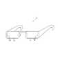
Next, a second modification of the electronic device which is an embodiment of the electronic device according to the present invention will be described with reference to FIG. FIG. 5 is a perspective view showing Modification Example 2 of the configuration of the electronic device according to the embodiment of the electronic device of the present invention. Note that the electronic device 1b of the following modified example 2 is different only in the configuration of the electronic device shown in FIG.
図5に示されるように、変形例2の電子機器1bでは、レンズ部12に形成されるアンテナ21bが、レンズ部12上において、レンズ部12から他のレンズ部13に向かう方向の逆方向側の方向の端部に形成されている。また、変形例2の電子機器1bでは、レンズ部13に形成されるアンテナ20bが、レンズ部13から他のレンズ部12向かう方向の逆側の方向の端部に形成されている。すなわち、変形例2では、図1に示されるアンテナ20の代わりにアンテナ20bを用い、図1に示されるアンテナ21の代わりにアンテナ21bを用いている。 As shown in FIG. 5, in the electronic device 1 b of Modification 2, the
このような構成とすることにより、変形例2の電子機器1bでは、前述の電子機器1の実施形態と同様の効果が得られると共に、アンテナ20bとアンテナ21bとの間の距離を確保することができ、両方のアンテナのダイバーシチ性能を向上させることができる。なお、アンテナ21b,20bのいずれか一方が、図5に示されるように、他のレンズに向かう方向の逆側の方向の端部に形成されていてもよい。 By adopting such a configuration, the electronic device 1b according to the second modification can obtain the same effects as those of the embodiment of the
[変形例3]
次に、本発明に係る電子機器の一実施形態である電子機器の変形例3について図6を参照して説明する。図6は、本発明の電子機器の一実施形態に係る電子機器の構成の変形例3を示す斜視図である。なお、以下の変形例3は、図1に示される電子機器の構成とアンテナ20,21の構造が異なるのみであるため、この異なる点のみを説明する。[Modification 3]
Next, Modification 3 of the electronic device which is an embodiment of the electronic device according to the present invention will be described with reference to FIG. FIG. 6 is a perspective view showing Modification Example 3 of the configuration of the electronic device according to the embodiment of the electronic device of the present invention. In the following modification 3, only the configuration of the electronic apparatus shown in FIG. 1 and the structure of the
図6に示されるように、変形例3の電子機器1cでは、レンズ部12に形成されるアンテナ21cが、レンズ部12上であって、レンズ部12から他のレンズ部13に向かう方向の逆側の方向の端隅部に形成されている。また、変形例3では、レンズ部13に形成されるアンテナ20cが、レンズ部13から他のレンズ部12に向かう方向の逆側の方向の端隅部に形成されている。ここで、端隅部とは、レンズ部上の位置であって、当該レンズ部から他のレンズ部に向かう方向の逆側の方向の端部であり、かつ、一方のレンズ部が他のレンズ部に向かう方向に垂直な方向の端部をいう。すなわち、変形例3では、図1に示されるアンテナ20の代わりにアンテナ20cを用い、図1に示されるアンテナ21の代わりにアンテナ21cを用いている。 As shown in FIG. 6, in the electronic device 1 c of the third modification, the
このような構成とすることにより、変形例3では、前述の電子機器1の実施形態と同様の効果が得られると共に、アンテナ20cとアンテナ21cとの間の距離を確保することができ、両方のアンテナのダイバーシチ性能を向上させることができる。なお、アンテナ21c,20cのいずれか一方が、図6に示されるように、他のレンズに向かう方向の逆側の端隅部に形成されていてもよい。 By adopting such a configuration, in Modification 3, the same effect as that of the embodiment of the
[変形例4]
次に、本発明に係る電子機器の一実施形態である電子機器の変形例4について図7を参照して説明する。図7は、本発明の電子機器の一実施形態に係る電子機器の構成の変形例4を示す斜視図である。なお、以下の変形例4は、図1に示される電子機器の構成と、レンズ部12,13及びアンテナ20,21の構造が異なるのみであるため、この異なる点のみを説明する。[Modification 4]
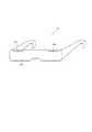
Next, Modification 4 of the electronic device which is an embodiment of the electronic device according to the present invention will be described with reference to FIG. FIG. 7: is a perspective view which shows the modification 4 of the structure of the electronic device which concerns on one Embodiment of the electronic device of this invention. The following modified example 4 is different from the configuration of the electronic device shown in FIG. 1 only in the structure of the
図5に示されるように、変形例4の電子機器1dでは、図1に示される実施形態のレンズ部12,13に対応するレンズ部が、右目用と左目用と分かれているのでは無く、一体型のレンズ部12bの構成となっている。なお、レンズ部12bの形状としては図6に示される形状に限定されるものではなく、適宜変形してもよい。 As shown in FIG. 5, in the
そして、変形例4の電子機器1dでは、図1に示される電子機器と同様に、アンテナ20d,21dが形成される。なお、このアンテナ20d,21dは、上述の変形例1,2,3のアンテナ配置と同様としてもよい。すなわち、変形例4では、図1に示されるアンテナ20の代わりにアンテナ20dを用い、図1に示されるアンテナ21の代わりにアンテナ21dを用いている。 And in the
このような構成とすることにより、変形例4では、前述の電子機器1の実施形態と同様の効果が得られる。 By adopting such a configuration, the modification 4 can obtain the same effects as those of the embodiment of the
なお、上記実施形態と各変形例は互いに矛盾しない範囲で任意に組み合わせることができる。例えば、レンズ部12に変形例1の構成のアンテナ21aを形成し、レンズ部13に変形例2の構成のアンテナ20bを形成するとしてもよい。 In addition, the said embodiment and each modification can be arbitrarily combined in the range which does not contradict each other. For example, the antenna 21 a having the configuration of
本発明を諸図面や実施例に基づき説明してきたが、当業者であれば本開示に基づき種々の変形や修正を行うことが容易であることに注意されたい。従って、これらの変形や修正は本発明の範囲に含まれることに留意されたい。例えば、各構成部、各ステップ等に含まれる機能等は論理的に矛盾しないように再配置可能であり、複数の構成部やステップ等を1つに組み合わせたり、或いは分割したりすることが可能である。また、本発明について装置を中心に説明してきたが、本発明は装置が備えるプロセッサにより実行される方法、プログラム、又はプログラムを記録した記憶媒体としても実現し得るものであり、本発明の範囲にはこれらも包含されるものと理解されたい。 Although the present invention has been described based on the drawings and examples, it should be noted that those skilled in the art can easily make various modifications and corrections based on the present disclosure. Therefore, it should be noted that these variations and modifications are included in the scope of the present invention. For example, the functions included in each component, each step, etc. can be rearranged so that there is no logical contradiction, and multiple components, steps, etc. can be combined or divided into one It is. Further, although the present invention has been described mainly with respect to the apparatus, the present invention can also be realized as a method, a program executed by a processor included in the apparatus, or a storage medium storing the program, and is within the scope of the present invention. It should be understood that these are also included.
1,1a,1b,1c,1d 電子機器
10,11 テンプル部
12 レンズ部(第1のレンズ部)
13 レンズ部(第2のレンズ部)
12b レンズ部
12a,13a リム部
14,15 鼻あて部
16 ブリッジ部
20,20a,20b,20c,20d アンテナ(第1のアンテナ)
21,21a,21b,21c,21d アンテナ(第2のアンテナ)
100,101 制御回路
110 電源部
120 RF部
130a,130b 整合回路部
140 制御部
150 記憶部1, 1a, 1b, 1c,
13 Lens part (second lens part)
21, 21a, 21b, 21c, 21d Antenna (second antenna)
100, 101
Claims (10)
Translated fromJapaneseユーザの目の前側に配置されるレンズ部と、
前記レンズ部に形成された第1のアンテナと、
前記レンズ部に形成された第2のアンテナと
備え、
前記第1のアンテナと前記第2のアンテナとは異なる機能のアンテナである電子機器。An electronic device that is worn on the user's head and used.
A lens unit disposed in front of the user's eyes;
A first antenna formed on the lens unit;
A second antenna formed on the lens unit;
An electronic apparatus in which the first antenna and the second antenna are antennas having different functions.
ユーザの一方の目の前方に配置される第1のレンズ部と、他方の目の前方に配置される第2のレンズ部と、を備える請求項1記載の電子機器。The lens part is
The electronic device according to claim 1, further comprising: a first lens unit disposed in front of one eye of the user; and a second lens unit disposed in front of the other eye.
前記第1のレンズ部から前記第2のレンズ部に向かう方向の逆方向側の端部に形成されている、請求項7記載の電子機器。The first antenna is
The electronic device according to claim 7, wherein the electronic device is formed at an end portion on a side opposite to a direction from the first lens portion toward the second lens portion.
前記第1のレンズ部から前記第2のレンズ部に向かう方向の逆方向側の端隅部に形成されている、請求項7記載の電子機器。The first antenna is
The electronic device according to claim 7, wherein the electronic device is formed at an end corner portion on a side opposite to a direction from the first lens portion toward the second lens portion.
Priority Applications (3)
| Application Number | Priority Date | Filing Date | Title |
|---|---|---|---|
| JP2016060456AJP2017175435A (en) | 2016-03-24 | 2016-03-24 | Electronic apparatus |
| US15/462,972US10381711B2 (en) | 2016-03-24 | 2017-03-20 | Electronic device |
| EP17161944.8AEP3223363A1 (en) | 2016-03-24 | 2017-03-21 | Electronic device |
Applications Claiming Priority (1)
| Application Number | Priority Date | Filing Date | Title |
|---|---|---|---|
| JP2016060456AJP2017175435A (en) | 2016-03-24 | 2016-03-24 | Electronic apparatus |
Publications (1)
| Publication Number | Publication Date |
|---|---|
| JP2017175435Atrue JP2017175435A (en) | 2017-09-28 |
Family
ID=58398062
Family Applications (1)
| Application Number | Title | Priority Date | Filing Date |
|---|---|---|---|
| JP2016060456APendingJP2017175435A (en) | 2016-03-24 | 2016-03-24 | Electronic apparatus |
Country Status (3)
| Country | Link |
|---|---|
| US (1) | US10381711B2 (en) |
| EP (1) | EP3223363A1 (en) |
| JP (1) | JP2017175435A (en) |
Cited By (2)
| Publication number | Priority date | Publication date | Assignee | Title |
|---|---|---|---|---|
| WO2022075463A1 (en)* | 2020-10-08 | 2022-04-14 | 大日本印刷株式会社 | Head-mounted display |
| JP2024541054A (en)* | 2021-11-05 | 2024-11-06 | グーグル エルエルシー | Detection of damage to display waveguides |
Families Citing this family (5)
| Publication number | Priority date | Publication date | Assignee | Title |
|---|---|---|---|---|
| US20180212314A1 (en)* | 2017-01-24 | 2018-07-26 | Intel Corporation | Wearable device sar reduction and antenna improvement |
| US11099639B1 (en)* | 2018-11-05 | 2021-08-24 | Facebook Technologies, Llc | Systems and methods for eye tracking in head-mounted display devices |
| WO2022055742A1 (en)* | 2020-09-08 | 2022-03-17 | Daedalus Labs Llc | Head-mounted devices with radar |
| EP4386979A4 (en) | 2021-10-18 | 2025-01-08 | Samsung Electronics Co., Ltd. | WEARABLE ELECTRONIC DEVICE COMPRISING AN ANTENNA |
| CN114879369A (en)* | 2022-06-15 | 2022-08-09 | 业成科技(成都)有限公司 | Wearable intelligent glasses communication device |
Citations (5)
| Publication number | Priority date | Publication date | Assignee | Title |
|---|---|---|---|---|
| JP2009541793A (en)* | 2006-06-23 | 2009-11-26 | ピクセルオプティクス, インコーポレイテッド | Electronic adapter for electroactive eyeglass lenses |
| WO2012086619A1 (en)* | 2010-12-22 | 2012-06-28 | シャープ株式会社 | Eyeglasses-type wireless communications apparatus |
| JP2013090061A (en)* | 2011-10-14 | 2013-05-13 | Sharp Corp | Wireless communication device |
| JP2014063166A (en)* | 2004-03-31 | 2014-04-10 | Swisscom Ag | Ophthalmic frame having acoustic communication system built in for communicating with mobile radio device and corresponding method |
| JP2015154276A (en)* | 2014-02-14 | 2015-08-24 | シャープ株式会社 | Portable terminal device |
Family Cites Families (8)
| Publication number | Priority date | Publication date | Assignee | Title |
|---|---|---|---|---|
| US3383682A (en) | 1966-10-24 | 1968-05-14 | Univ Utah | Radar glasses for the blind |
| JPS53444A (en) | 1976-06-25 | 1978-01-06 | Mikuni Kogyo Co Ltd | Gas supply control device |
| GB2291551B (en) | 1994-06-24 | 1998-03-18 | Roscoe C Williams Limited | Electronic viewing aid |
| JPH11353444A (en) | 1998-06-05 | 1999-12-24 | Teruya:Kk | Information management system with personal information built-in glasses |
| US7769348B2 (en)* | 2006-11-24 | 2010-08-03 | Sony Ericsson Mobile Communications Ab | Ad-hoc connectivity system and method |
| US7874666B2 (en)* | 2007-03-26 | 2011-01-25 | University Of Washington Through Its Center For Commercialization | Smart sunglasses, helmet faceshields and goggles based on electrochromic polymers |
| GB2476033A (en) | 2009-12-04 | 2011-06-15 | Marcus Lewis | Personal audio equipment device |
| JP5767082B2 (en) | 2011-11-04 | 2015-08-19 | シャープ株式会社 | Glasses type wireless communication device |
- 2016
- 2016-03-24JPJP2016060456Apatent/JP2017175435A/enactivePending
- 2017
- 2017-03-20USUS15/462,972patent/US10381711B2/enactiveActive
- 2017-03-21EPEP17161944.8Apatent/EP3223363A1/ennot_activeWithdrawn
Patent Citations (5)
| Publication number | Priority date | Publication date | Assignee | Title |
|---|---|---|---|---|
| JP2014063166A (en)* | 2004-03-31 | 2014-04-10 | Swisscom Ag | Ophthalmic frame having acoustic communication system built in for communicating with mobile radio device and corresponding method |
| JP2009541793A (en)* | 2006-06-23 | 2009-11-26 | ピクセルオプティクス, インコーポレイテッド | Electronic adapter for electroactive eyeglass lenses |
| WO2012086619A1 (en)* | 2010-12-22 | 2012-06-28 | シャープ株式会社 | Eyeglasses-type wireless communications apparatus |
| JP2013090061A (en)* | 2011-10-14 | 2013-05-13 | Sharp Corp | Wireless communication device |
| JP2015154276A (en)* | 2014-02-14 | 2015-08-24 | シャープ株式会社 | Portable terminal device |
Cited By (2)
| Publication number | Priority date | Publication date | Assignee | Title |
|---|---|---|---|---|
| WO2022075463A1 (en)* | 2020-10-08 | 2022-04-14 | 大日本印刷株式会社 | Head-mounted display |
| JP2024541054A (en)* | 2021-11-05 | 2024-11-06 | グーグル エルエルシー | Detection of damage to display waveguides |
Also Published As
| Publication number | Publication date |
|---|---|
| US20170279183A1 (en) | 2017-09-28 |
| EP3223363A1 (en) | 2017-09-27 |
| US10381711B2 (en) | 2019-08-13 |
Similar Documents
| Publication | Publication Date | Title |
|---|---|---|
| JP2017175435A (en) | Electronic apparatus | |
| US9866282B2 (en) | Magnetic induction antenna for use in a wearable device | |
| JP6566498B2 (en) | Multiband antenna for wearable glasses | |
| EP3469809B1 (en) | Wireless headset | |
| EP2723101B1 (en) | Bte hearing aid having a balanced antenna | |
| JP6576280B2 (en) | Electronics | |
| US9554219B2 (en) | BTE hearing aid having a balanced antenna | |
| US20140010392A1 (en) | Bte hearing aid having two driven antennas | |
| US20180146305A1 (en) | A hearing aid having combined antennas | |
| US10547946B2 (en) | Wearable device | |
| US20140010394A1 (en) | Bte hearing aid with an antenna partition plane | |
| US9877119B2 (en) | Hearing aid with antenna on printed circuit board | |
| CN112350047B (en) | Wearable equipment | |
| US20180270900A1 (en) | Antenna system for head mounted display device | |
| US10972824B1 (en) | Wireless earphone | |
| EP3373389B1 (en) | Wireless device antenna | |
| JP2017175436A (en) | Electronic apparatus | |
| DK3185583T3 (en) | Hearing aid with antenna on circuit board | |
| KR102143849B1 (en) | Terminal | |
| CN115956326A (en) | Antenna structure and electronic wearable devices | |
| US20240146340A1 (en) | Antenna system with conductive shielding and loss mitigation | |
| EP4343964A1 (en) | Controlling antenna radiation patterns in artificial reality devices | |
| CN120728229A (en) | A wearable device | |
| DK179697B1 (en) | Hearing aid with antenna on printed circuit board | |
| CN120476517A (en) | Head-mounted electronic device and antenna structure |
Legal Events
| Date | Code | Title | Description |
|---|---|---|---|
| A621 | Written request for application examination | Free format text:JAPANESE INTERMEDIATE CODE: A621 Effective date:20180625 | |
| A977 | Report on retrieval | Free format text:JAPANESE INTERMEDIATE CODE: A971007 Effective date:20190322 | |
| A131 | Notification of reasons for refusal | Free format text:JAPANESE INTERMEDIATE CODE: A131 Effective date:20190409 | |
| A521 | Request for written amendment filed | Free format text:JAPANESE INTERMEDIATE CODE: A523 Effective date:20190531 | |
| A131 | Notification of reasons for refusal | Free format text:JAPANESE INTERMEDIATE CODE: A131 Effective date:20190618 | |
| A02 | Decision of refusal | Free format text:JAPANESE INTERMEDIATE CODE: A02 Effective date:20191210 |