JP2017174447A - Underwater camera operating method - Google Patents
Underwater camera operating methodDownload PDFInfo
- Publication number
- JP2017174447A JP2017174447AJP2017093158AJP2017093158AJP2017174447AJP 2017174447 AJP2017174447 AJP 2017174447AJP 2017093158 AJP2017093158 AJP 2017093158AJP 2017093158 AJP2017093158 AJP 2017093158AJP 2017174447 AJP2017174447 AJP 2017174447A
- Authority
- JP
- Japan
- Prior art keywords
- touch
- electrode
- camera
- touch screen
- underwater
- Prior art date
- Legal status (The legal status is an assumption and is not a legal conclusion. Google has not performed a legal analysis and makes no representation as to the accuracy of the status listed.)
- Pending
Links
Images


Classifications
- G—PHYSICS
- G06—COMPUTING OR CALCULATING; COUNTING
- G06F—ELECTRIC DIGITAL DATA PROCESSING
- G06F3/00—Input arrangements for transferring data to be processed into a form capable of being handled by the computer; Output arrangements for transferring data from processing unit to output unit, e.g. interface arrangements
- G06F3/01—Input arrangements or combined input and output arrangements for interaction between user and computer
- G06F3/03—Arrangements for converting the position or the displacement of a member into a coded form
- G06F3/041—Digitisers, e.g. for touch screens or touch pads, characterised by the transducing means
- G06F3/044—Digitisers, e.g. for touch screens or touch pads, characterised by the transducing means by capacitive means
- G06F3/0445—Digitisers, e.g. for touch screens or touch pads, characterised by the transducing means by capacitive means using two or more layers of sensing electrodes, e.g. using two layers of electrodes separated by a dielectric layer
- G—PHYSICS
- G03—PHOTOGRAPHY; CINEMATOGRAPHY; ANALOGOUS TECHNIQUES USING WAVES OTHER THAN OPTICAL WAVES; ELECTROGRAPHY; HOLOGRAPHY
- G03B—APPARATUS OR ARRANGEMENTS FOR TAKING PHOTOGRAPHS OR FOR PROJECTING OR VIEWING THEM; APPARATUS OR ARRANGEMENTS EMPLOYING ANALOGOUS TECHNIQUES USING WAVES OTHER THAN OPTICAL WAVES; ACCESSORIES THEREFOR
- G03B17/00—Details of cameras or camera bodies; Accessories therefor
- G03B17/02—Bodies
- G03B17/08—Waterproof bodies or housings
- G—PHYSICS
- G06—COMPUTING OR CALCULATING; COUNTING
- G06F—ELECTRIC DIGITAL DATA PROCESSING
- G06F3/00—Input arrangements for transferring data to be processed into a form capable of being handled by the computer; Output arrangements for transferring data from processing unit to output unit, e.g. interface arrangements
- G06F3/01—Input arrangements or combined input and output arrangements for interaction between user and computer
- G06F3/03—Arrangements for converting the position or the displacement of a member into a coded form
- G06F3/041—Digitisers, e.g. for touch screens or touch pads, characterised by the transducing means
- G06F3/044—Digitisers, e.g. for touch screens or touch pads, characterised by the transducing means by capacitive means
- G06F3/0446—Digitisers, e.g. for touch screens or touch pads, characterised by the transducing means by capacitive means using a grid-like structure of electrodes in at least two directions, e.g. using row and column electrodes
- G—PHYSICS
- G06—COMPUTING OR CALCULATING; COUNTING
- G06F—ELECTRIC DIGITAL DATA PROCESSING
- G06F3/00—Input arrangements for transferring data to be processed into a form capable of being handled by the computer; Output arrangements for transferring data from processing unit to output unit, e.g. interface arrangements
- G06F3/01—Input arrangements or combined input and output arrangements for interaction between user and computer
- G06F3/03—Arrangements for converting the position or the displacement of a member into a coded form
- G06F3/041—Digitisers, e.g. for touch screens or touch pads, characterised by the transducing means
- G06F3/044—Digitisers, e.g. for touch screens or touch pads, characterised by the transducing means by capacitive means
- G06F3/0447—Position sensing using the local deformation of sensor cells
- H—ELECTRICITY
- H04—ELECTRIC COMMUNICATION TECHNIQUE
- H04N—PICTORIAL COMMUNICATION, e.g. TELEVISION
- H04N23/00—Cameras or camera modules comprising electronic image sensors; Control thereof
- H04N23/50—Constructional details
- H04N23/51—Housings
- H—ELECTRICITY
- H04—ELECTRIC COMMUNICATION TECHNIQUE
- H04N—PICTORIAL COMMUNICATION, e.g. TELEVISION
- H04N23/00—Cameras or camera modules comprising electronic image sensors; Control thereof
- H04N23/60—Control of cameras or camera modules
- H04N23/667—Camera operation mode switching, e.g. between still and video, sport and normal or high- and low-resolution modes
- G—PHYSICS
- G06—COMPUTING OR CALCULATING; COUNTING
- G06F—ELECTRIC DIGITAL DATA PROCESSING
- G06F2200/00—Indexing scheme relating to G06F1/04 - G06F1/32
- G06F2200/16—Indexing scheme relating to G06F1/16 - G06F1/18
- G06F2200/163—Indexing scheme relating to constructional details of the computer
- G06F2200/1633—Protecting arrangement for the entire housing of the computer
- G—PHYSICS
- G06—COMPUTING OR CALCULATING; COUNTING
- G06F—ELECTRIC DIGITAL DATA PROCESSING
- G06F2203/00—Indexing scheme relating to G06F3/00 - G06F3/048
- G06F2203/041—Indexing scheme relating to G06F3/041 - G06F3/045
- G06F2203/04105—Pressure sensors for measuring the pressure or force exerted on the touch surface without providing the touch position
- G—PHYSICS
- G06—COMPUTING OR CALCULATING; COUNTING
- G06F—ELECTRIC DIGITAL DATA PROCESSING
- G06F2203/00—Indexing scheme relating to G06F3/00 - G06F3/048
- G06F2203/041—Indexing scheme relating to G06F3/041 - G06F3/045
- G06F2203/04106—Multi-sensing digitiser, i.e. digitiser using at least two different sensing technologies simultaneously or alternatively, e.g. for detecting pen and finger, for saving power or for improving position detection
- G—PHYSICS
- G06—COMPUTING OR CALCULATING; COUNTING
- G06F—ELECTRIC DIGITAL DATA PROCESSING
- G06F3/00—Input arrangements for transferring data to be processed into a form capable of being handled by the computer; Output arrangements for transferring data from processing unit to output unit, e.g. interface arrangements
- G06F3/01—Input arrangements or combined input and output arrangements for interaction between user and computer
- G06F3/03—Arrangements for converting the position or the displacement of a member into a coded form
- G06F3/041—Digitisers, e.g. for touch screens or touch pads, characterised by the transducing means
- G06F3/0416—Control or interface arrangements specially adapted for digitisers
Landscapes
- Engineering & Computer Science (AREA)
- General Engineering & Computer Science (AREA)
- Theoretical Computer Science (AREA)
- Physics & Mathematics (AREA)
- General Physics & Mathematics (AREA)
- Human Computer Interaction (AREA)
- Multimedia (AREA)
- Signal Processing (AREA)
- User Interface Of Digital Computer (AREA)
- Structure And Mechanism Of Cameras (AREA)
- Studio Devices (AREA)
- Camera Bodies And Camera Details Or Accessories (AREA)
Abstract
Description
Translated fromJapanese 本発明は、カメラの水中操作方法に関するもので、より詳しくは、水中でタッチ圧力
を利用してタッチ位置を検出することができるカメラの水中操作方法に関する。The present invention relates to an underwater operation method for a camera, and more particularly to an underwater operation method for a camera capable of detecting a touch position using a touch pressure in water.
コンピューティングシステムの操作のために多様な種類の入力装置が用いられている
。例えば、ボタン(button)、キー(key)、ジョイステック(joystic
k)、及びタッチスクリーンのような入力装置が用いられている。タッチスクリーンの容
易で手軽な操作により、コンピューティングシステムの操作時にタッチスクリーンの利用
が増加している。Various types of input devices are used to operate computing systems. For example, button, key, joystick
k), and input devices such as touch screens are used. Due to the easy and easy operation of touch screens, the use of touch screens is increasing when operating computing systems.
タッチスクリーンは、タッチ−感応表面(touch−sensitive sur
face)を備えた透明なパネルであってもよいタッチセンサーパネル(touch s
ensor panel)を含んでもよい。このようなタッチセンサーパネルは、ディス
プレイパネルの前面に付着されてタッチ−感応表面がディスプレイパネルの見える面を覆
うことができる。タッチスクリーンは、使用者が指などでスクリーンを単純に接触するこ
とにより、使用者がコンピューティングシステムを操作することができるようにする。一
般的に、タッチスクリーンは、パネル上の接触及び接触位置を認識し、コンピューティン
グシステムはこのような接触を解釈することにより、これに従い演算を行うことができる
。Touch screens are touch-sensitive surfaces.
touch sensor panel (touch s), which may be a transparent panel with face
(enensor panel). Such a touch sensor panel can be attached to the front surface of the display panel so that the touch-sensitive surface covers the visible surface of the display panel. The touch screen allows the user to operate the computing system by simply touching the screen with a finger or the like. In general, the touch screen recognizes touches and touch positions on the panel, and the computing system can interpret such touches and perform calculations accordingly.
しかし、前記タッチスクリーンは、水中で正常な動作が不可能であるため、前記タッ
チスクリーンを備えたカメラは、水中でタッチを利用して撮影することができない問題が
あった。However, since the touch screen cannot operate normally underwater, the camera having the touch screen has a problem in that it cannot capture images using touch underwater.
したがって、水中でタッチを利用して撮影することができるようにする研究が必要に
なった。Therefore, research has become necessary to be able to shoot underwater using touch.
そこで、本発明の様々な実施形態により、水中でタッチ圧力を利用してタッチ位置を
検出することができるカメラの水中操作方法を提供する。Therefore, according to various embodiments of the present invention, a camera underwater operation method capable of detecting a touch position using a touch pressure in water is provided.
本発明の実施形態によるカメラの水中操作方法は、タッチスクリーン、プロセッサ、
及び制御部を含むタッチ入力装置に内蔵されたカメラの水中操作方法において、水中でタ
ッチ圧力による静電容量の変化量でタッチ位置を検出する第1駆動モードが動作される段
階と、客体による前記タッチスクリーンに対するタッチを通じてカメラの動作を水中で制
御する段階と、を含む。An underwater operation method of a camera according to an embodiment of the present invention includes a touch screen, a processor,
In the underwater operation method of the camera built in the touch input device including the control unit, the step of detecting the touch position by the amount of change in the electrostatic capacity due to the touch pressure in the water is operated, and the object by the object Controlling the operation of the camera underwater through a touch on the touch screen.
本発明の様々な実施形態によれば、水中でタッチ圧力を利用してタッチ位置を検出す
ることができるカメラの水中操作方法を提供することができる。According to various embodiments of the present invention, it is possible to provide an underwater operation method of a camera that can detect a touch position using a touch pressure in water.
また、本発明の実施形態によれば、自動で水中であることを判断するカメラの水中操
作方法を提供することができる。Moreover, according to the embodiment of the present invention, it is possible to provide an underwater operation method for a camera that automatically determines that it is underwater.
後述する本発明に対する詳細な説明は、本発明を実施することができる特定の実施形
態を例示として図示する添付の図面を参照する。これらの実施形態は、当業者が本発明を
実施するのに十分なように詳しく説明する。本発明の多様な実施形態は互いに異なるが、
相互に排他的である必要はないことが理解されなければならない。後述する詳細な説明は
、限定的な意味として取ろうとするのではなく、本発明の範囲は、適切に説明されるなら
ば、その請求項が主張するのと均等なすべての範囲とともに添付された請求項によっての
み限定される。図面において類似の参照符号は様々な側面にわたって同一もしくは類似の
機能を指し示す。The following detailed description of the invention refers to the accompanying drawings that illustrate, by way of illustration, specific embodiments in which the invention may be practiced. These embodiments are described in sufficient detail to enable those skilled in the art to practice the invention. Although various embodiments of the present invention are different from each other,
It should be understood that they need not be mutually exclusive. The following detailed description is not to be taken in a limiting sense, but the scope of the present invention, if properly described, is appended along with all equivalents of the claims that are claimed. Limited only by the claims. In the drawings, like reference numbers indicate identical or similar functions throughout the various aspects.
以下、添付される図面を参照して本発明の実施形態によるタッチスクリーン130を
含むタッチ入力装置100を説明する。本発明の実施形態によるタッチ入力装置100の
機能及び特徴を詳しくみる前に、タッチ入力装置100に含まれるタッチスクリーン13
0について図10ないし図18を参照して詳しく見てみる。Hereinafter, a
Let us take a closer look at 0 with reference to FIGS.
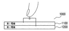
図10は、第1実施形態によるタッチスクリーンの構造図を例示する。 FIG. 10 illustrates a structural diagram of the touch screen according to the first embodiment.
図10に示されたように、タッチスクリーン130は、タッチ位置感知モジュール1
000、前記タッチ位置感知モジュール1000の下部に配置されたタッチ圧力感知モジ
ュール2000、前記タッチ圧力感知モジュール2000の下部に配置されたディスプレ
イモジュール3000、及び前記ディスプレイモジュール3000の下部に配置された基
板4000を含んでもよい。例えば、タッチ位置感知モジュール1000及びタッチ圧力
感知モジュール2000は、タッチ−感応表面(touch−sensitive su
rface)を備えた透明なパネルであってもよい。以下で、タッチ位置及び/又はタッ
チ圧力を感知するためのモジュール1000、2000、3000、5000は、統合的
にタッチ感知モジュールと指称されてもよい。As shown in FIG. 10, the
000, a touch
It may be a transparent panel provided with (rface). Hereinafter, the
ディスプレイモジュール3000は、使用者が視覚的に内容を確認できるように画面
をディスプレイすることができる。この時、ディスプレイモジュール3000に対するデ
ィスプレイは、ディスプレイドライバー(display driver)を介して行わ
れてもよい。ディスプレイドライバー(図示せず)は、運営体制がディスプレイアダプタ
を管理又は制御するためのソフトウェアであって、装置ドライバーの一種である。The
図11aないし図11dは、第1実施形態によるタッチ位置感知モジュールの構造図
であり、図18aないし図18cは、実施形態によるタッチ位置感知モジュールに形成さ
れた電極の形態を示す構造図である。FIGS. 11a to 11d are structural views of the touch position sensing module according to the first embodiment, and FIGS. 18a to 18c are structural views illustrating forms of electrodes formed on the touch position sensing module according to the embodiment.
図11aに示されたように、実施形態によるタッチ位置感知モジュール1000は、
一つの層に形成された第1電極1100を含んでもよい。この時、第1電極1100は、
図18aに示された形態のように複数の電極6100で構成されて、それぞれの電極61
00に駆動信号が入力され、それぞれの電極から自己静電容量に関する情報を含む感知信
号が出力されてもよい。使用者の指のような客体が第1電極1100に近接する場合、指
がグランドの役割をして、第1電極1100の自己静電容量が変わることになる。したが
って、タッチ入力装置100は、タッチスクリーン130に使用者の指のような客体が近
接することによって変わる第1電極1100の自己静電容量を測定してタッチ位置を検出
することができる。As shown in FIG. 11a, the touch
The
As shown in FIG. 18a, each electrode 61 is composed of a plurality of
A drive signal may be input to 00, and a sensing signal including information on self-capacitance may be output from each electrode. When an object such as a user's finger approaches the
図11bに示されたように、実施形態によるタッチ位置感知モジュール1000は、
互いに異なる層に形成された第1電極1100及び第2電極1200を含んでもよい。As shown in FIG. 11b, the touch
The
この時、第1電極1100及び第2電極1200は、図18bに示された形態のよう
に、それぞれ複数の第1電極6200と複数の第2電極6300で構成され、それぞれ互
いに交差するように配列されてもよく、第1電極6200又は第2電極6300のうち何
れか一つに駆動信号が入力され、他の一つから相互静電容量に関する情報を含む感知信号
が出力されてもよい。図11bに示されたように、使用者の指のような客体が第1電極1
100及び第2電極1200に近接する場合、指がグランドの役割をして、第1電極11
00と第2電極1200との間の相互静電容量が変わることになる。この場合、タッチ入
力装置100は、タッチスクリーン130に使用者の指のような客体が近接することによ
って変わる第1電極1100と第2電極1200との間の相互静電容量を測定してタッチ
位置を検出することができる。また、第1電極6200及び第2電極6300に駆動信号
が入力され、それぞれの第1電極6200及び第2電極6300から自己静電容量に関す
る情報を含む感知信号が出力されてもよい。図11cに示されたように、使用者の指のよ
うな客体が第1電極1100及び第2電極1200に近接する場合、指がグランド役割を
して、第1電極1100及び第2電極1200それぞれの自己静電容量が変わることにな
る。この場合、タッチ入力装置100は、タッチスクリーン130に使用者の指のような
客体が近接することによって変わる第1電極1100及び第2電極1200の自己静電容
量を測定してタッチ位置を検出することができる。At this time, the
100 and the
The mutual capacitance between 00 and the
図11dに示されたように、実施形態によるタッチ位置感知モジュール1000は、
一つの層に形成された第1電極1100及び前記第1電極1100が形成された層と同じ
層に形成された第2電極1200を含んでもよい。As shown in FIG. 11d, the touch
A
この時、第1電極1100及び第2電極1200は、図18cに示された形態のよう
に、それぞれ複数の第1電極6400と複数の第2電極6500で構成され、複数の第1
電極6400と複数の第2電極6500はそれぞれ互いに交差しないながらも、それぞれ
の第1電極6400が延びた方向と交差する方向にそれぞれの第2電極6500が連結さ
れるように配列されてもよく、図11dに示された第1電極6400又は第2電極650
0を用いてタッチ位置を検出する原理は、図11cを参照して説明されたことと同一なの
で省略する。At this time, each of the
The
The principle of detecting the touch position using 0 is the same as that described with reference to FIG.
図12aないし図12fは、第1実施形態によるタッチ圧力感知モジュールの構造図
であり、図18aないし図18dは、実施形態によるタッチ圧力感知モジュールに形成さ
れた電極の形態を示す構造図である。FIGS. 12a to 12f are structural views of the touch pressure sensing module according to the first embodiment, and FIGS. 18a to 18d are structural views illustrating forms of electrodes formed on the touch pressure sensing module according to the embodiment.
図12aないし図12fに示されたように、第1実施形態によるタッチ圧力感知モジ
ュール2000は、スペーサ層2400を含んでもよい。スペーサ層2400は、エアギ
ャップ(air gap)で具現されてもよい。スペーサは、実施形態により衝撃吸収物
質からなってもよく、また、実施形態により誘電物質(dielectric mate
rial)で満たされてもよい。As shown in FIGS. 12 a to 12 f, the touch
(riial).
図12aないし図12dに示されたように、第1実施形態によるタッチ圧力感知モジ
ュール2000は、基準電位層2500を含んでもよい。基準電位層2500は、任意の
電位を有してもよい。例えば、基準電位層は、グランド(ground)電位を有するグ
ランド層であってもよい。この時、基準電位層は、後述することになるタッチ圧力を感知
するための第1電極2100が形成された2次元平面又は第2電極2200が形成された
2次元平面と平行した平面を有してもよい。図12aないし図12dにおいては、タッチ
圧力感知モジュール2000が基準電位層2500を含むものと説明したが、必ずしもこ
れに限定される訳ではなく、タッチ圧力感知モジュール2000が基準電位層2500を
含まず、タッチ圧力感知モジュール2000の下部に配置されたディスプレイモジュール
3000又は基板4000が基準電位層の役割をすることができる。12A to 12D, the touch
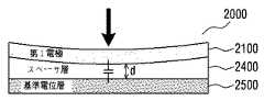
図12aに示されたように、実施形態によるタッチ圧力感知モジュール2000は、
一つの層に形成された第1電極2100、前記第1電極2100が形成された層の下部に
形成されたスペーサ層2400、及び前記スペーサ層2400の下部に形成された基準電
位層2500を含んでもよい。As shown in FIG. 12a, the touch
The
この時、第1電極2100は、図18aに示された形態のように、複数の電極610
0で構成されて、それぞれの電極6100に駆動信号が入力され、それぞれの電極から自
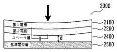
己静電容量に関する情報を含む感知信号が出力されてもよい。使用者の指又はスタイラス
のような客体によってタッチスクリーン130に圧力が加えられる場合、図12bに示さ
れたように、第1電極2100が少なくともタッチ位置でたわむことになり、第1電極2
100と基準電位層2500との間の距離dが変わることになって、これにより、第1電
極2100の自己静電容量が変わることになる。したがって、タッチ入力装置100は、
タッチスクリーン130に使用者の指又はスタイラスのような客体により、圧力が加えら
れることによって変わる第1電極2100の自己静電容量を測定してタッチ圧力を検出す
ることができる。このように、第1電極2100が複数の電極6100で構成されている
ので、タッチスクリーン130に同時に入力されたマルチタッチそれぞれの圧力を検出す
ることができる。また、マルチタッチそれぞれの圧力を検出する必要がない場合、タッチ
位置とは関係なく、タッチスクリーン130に加えられる全体的な圧力だけ検出すればよ
いので、タッチ圧力感知モジュール2000の第1電極2100は、図18dに示された
形態のように一つの電極6600で構成されてもよい。At this time, the
The driving signal may be input to each
The distance d between 100 and the
The touch pressure can be detected by measuring the self-capacitance of the
図12cに示されたように、実施形態によるタッチ圧力感知モジュール2000は、
第1電極2100、第1電極2100が形成された層の下部に形成された第2電極220
0、前記第2電極2200が形成された層の下部に形成されたスペーサ層2400、及び
前記スペーサ層2400の下部に形成された基準電位層2500を含んでもよい。As shown in FIG. 12c, the touch
The
0, a
この時、第1電極2100及び第2電極2200は、図18bに示された形態のよう
に構成及び配列されてもよく、第1電極6200又は第2電極6300の何れか一つに駆
動信号が入力され、他の一つから相互静電容量に関する情報を含む感知信号が出力されて
もよい。タッチスクリーン130に圧力が加えられる場合、図12dに示されたように、
第1電極2100及び第2電極2200が少なくともタッチ位置でたわむことになり、第
1電極2100及び第2電極2200と基準電位層2500との間の距離dが変わること
になり、これにより、第1電極2100と第2電極2200との間の相互静電容量が変わ
ることになる。したがって、タッチ入力装置100は、タッチスクリーン130に圧力が
加えられることによって変わる第1電極2100と第2電極2200との間の相互静電容
量を測定してタッチ圧力を検出することができる。このように、第1電極2100及び第
2電極2200がそれぞれ複数の第1電極6200及び複数の第2電極6300で構成さ
れているので、タッチスクリーン130に同時に入力されたマルチタッチそれぞれの圧力
を検出することができる。また、マルチタッチそれぞれの圧力を検出する必要がない場合
、タッチ圧力感知モジュール2000の第1電極2100及び第2電極2200のうち少
なくとも一つは、図18dに示された形態のように一つの電極6600で構成されてもよ
い。At this time, the
The
この時、第1電極2100と第2電極2200が同一の層に形成された場合にも、図
12cで説明したことと同様に、タッチ圧力が感知されてもよい。ただし、第1電極21
00及び第2電極2200は、図18cに示された形態のように構成及び配列されてもよ
く、図18dに示された形態のように一つの電極6600で構成されてもよい。At this time, when the
00 and the
図12eに示されたように、実施形態によるタッチ圧力感知モジュール2000は、
一つの層に形成された第1電極2100、前記第1電極2100が形成された層の下部に
形成されたスペーサ層2400、及び前記スペーサ層2400の下部層に形成された第2
電極2200を含んでもよい。As shown in FIG. 12e, the touch
A
An
図12eにおいて第1電極2100と第2電極2200の構成及び動作は、図12c
を参照して説明したことと同一なので省略する。ただし、タッチスクリーン130に圧力
が加えられる場合、図12fに示されたように、第1電極2100が少なくともタッチ位
置でたわむことになり、第1電極2100と第2電極2200との間の距離dが変わるこ
とになって、これにより、第1電極2100と第2電極2200との間の相互静電容量が
変わることになる。したがって、タッチ入力装置100は、第1電極2100と第2電極
2200との間の相互静電容量を測定してタッチ圧力を検出することができる。The configuration and operation of the
Since it is the same as that described with reference to FIG. However, when pressure is applied to the
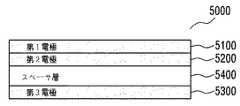
図13に示されたように、第2実施形態によるタッチスクリーン130は、タッチ位
置−圧力感知モジュール5000、前記タッチ位置−圧力感知モジュール5000の下部
に配置されたディスプレイモジュール3000、及び前記ディスプレイモジュール300
0の下部に配置された基板4000を含んでもよい。As shown in FIG. 13, the
The
図10に示された実施形態と異なり、図13に示された実施形態によるタッチ位置−
圧力感知モジュール5000は、タッチ位置を感知するための少なくとも一つの電極及び
タッチ圧力を感知するための少なくとも一つの電極を含むが、前記電極のうち少なくとも
一つの電極がタッチ位置及びタッチ圧力を感知するのに全て使用される。このようにタッ
チ位置を感知するための電極とタッチ圧力を感知するための電極を共有することにより、
タッチ位置−圧力感知モジュールの製造単価が低くなり、全体的なタッチスクリーン13
0の厚さを低減させることができ、製造工程が単純になり得る。このようにタッチ位置を
感知するための電極とタッチ圧力を感知するための電極とを共有する場合において、タッ
チ位置に対する情報を含む感知信号とタッチ圧力に対する情報を含む感知信号との区分が
必要な場合、タッチ位置を感知するための駆動信号とタッチ圧力を感知するための駆動信
号との周波数を別にしたり、タッチ位置を感知する時間区間とタッチ圧力を感知する時間
区間とを別にして、タッチ位置とタッチ圧力とを区分して感知することができる。Unlike the embodiment shown in FIG. 10, the touch position according to the embodiment shown in FIG.
The
The manufacturing cost of the touch position-pressure sensing module is lowered, and the overall touch screen 13
The thickness of zero can be reduced and the manufacturing process can be simplified. Thus, in the case where the electrode for sensing the touch position and the electrode for sensing the touch pressure are shared, it is necessary to distinguish between the sensing signal including information on the touch position and the sensing signal including information on the touch pressure. In this case, the frequency of the drive signal for sensing the touch position and the drive signal for sensing the touch pressure is separated, or the time interval for sensing the touch position and the time interval for sensing the touch pressure are separated, The touch position and the touch pressure can be distinguished and sensed.
図14aないし図14kは、第2実施形態によるタッチ位置−圧力感知モジュールの
構造図である。図14aないし図14kに示されたように、第2実施形態によるタッチ位
置−圧力感知モジュール5000は、スペーサ層5400を含んでもよい。14a to 14k are structural views of a touch position-pressure sensing module according to a second embodiment. 14a to 14k, the touch position-
図14aないし図14iに示されたように、実施形態によるタッチ位置−圧力感知モ
ジュール5000は、基準電位層5500を含んでもよい。基準電位層5500に対する
説明は、図12aないし図12dを参照して説明したことと同一なので省略する。ただし
、基準電位層は、後述することになるタッチ圧力を感知するための第1電極5100が形
成された2次元平面、第2電極5200が形成された2次元平面又は第3電極5300が
形成された2次元平面と平行した平面を有してもよい。As shown in FIGS. 14 a to 14 i, the touch position-
図14aに示されたように、実施形態によるタッチ位置−圧力感知モジュール500
0は、一つの層に形成された第1電極5100、前記第1電極5100が形成された層の
下部に形成されたスペーサ層5400、及び前記スペーサ層5400の下部に形成された
基準電位層5500を含んでもよい。As shown in FIG. 14a, a touch position-
図14a及び図14bの構成に対する説明は、図12a及び図12bを参照した説明
と類似しており、以下ではその差異点のみを説明する。図14bに示されたように、使用
者の指のような客体が第1電極5100に近接する場合、指がグランドの役割をして、第
1電極5100の自己静電容量の変化を通じてタッチ位置を検出でき、また、前記客体に
よってタッチスクリーン130に圧力が加えられる場合、第1電極5100と基準電位層
5500との間の距離dが変わることになり、これにより、第1電極2100の自己静電
容量の変化を通じてタッチ圧力を検出することができる。The description of the configuration of FIGS. 14a and 14b is similar to the description with reference to FIGS. 12a and 12b, and only the differences will be described below. As shown in FIG. 14 b, when an object such as a user's finger is close to the
図14cに示されたように、実施形態によるタッチ位置−圧力感知モジュール500
0は、一つの層に形成された第1電極5100、前記第1電極5100が形成された層の
下部層に形成された第2電極5200、前記第2電極5200が形成された層の下部に形
成されたスペーサ層5400、及び前記スペーサ層5400の下部に形成された基準電位
層5500を含んでもよい。As shown in FIG. 14c, the touch position-
0 is a
図14cないし図14fの構成に対する説明は、図12c及び図12dを参照した説
明と類似しており、以下ではその差異点のみを説明する。この時、第1電極5100及び
第2電極5200は、図18aに示された形態のように、それぞれ複数の電極6100で
構成されてもよい。図14dに示されたように、使用者の指のような客体が第1電極51
00に近接する場合、指がグランドの役割をして、第1電極5100の自己静電容量の変
化を通じてタッチ位置を検出でき、また、前記客体によってタッチスクリーン130に圧
力が加えられる場合、第1電極5100及び第2電極5200と基準電位層5500との
間の距離dが変わることになり、これにより、第1電極5100と第2電極5200との
間の相互静電容量の変化を通じてタッチ圧力を検出することができる。The description of the configuration of FIGS. 14c to 14f is similar to the description with reference to FIGS. 12c and 12d, and only the differences will be described below. At this time, each of the
When the finger is close to 00, the finger can act as a ground, and the touch position can be detected through a change in the self-capacitance of the
また、実施形態により第1電極5100及び第2電極5200は、図18bに示され
た形態のように、それぞれ複数の第1電極6200と複数の第2電極6300で構成され
、それぞれ互いに交差するように配列されてもよい。この時、第1電極5100と第2電
極5200との間の相互静電容量の変化を通じてタッチ位置を検出でき、第2電極520
0と基準電位層5500との間の距離dが変化に伴う第2電極5200の自己静電容量の
変化を通じてタッチ圧力を検出することができる。また、実施形態により、第1電極51
00と第2電極5200との間の相互静電容量の変化を通じてタッチ位置を検出でき、ま
た、第1電極5100及び第2電極5200と基準電位層5500との間の距離dが変化
に伴う第1電極5100と第2電極5200との間の相互静電容量の変化を通じてタッチ
圧力を検出することができる。In addition, according to the embodiment, the
The touch pressure can be detected through a change in the self-capacitance of the
The touch position can be detected through a change in mutual capacitance between the
この時、第1電極5100と第2電極5200が同一の層に形成された場合にも、図
14c及び図14dを参照して説明したことと同様に、タッチ位置及び圧力が感知されて
もよい。ただし、図14c及び図14dにおいて、電極が図18bのように構成されなけ
ればならない実施形態に対しては、第1電極5100及び第2電極5200が同一の層に
形成される場合には、図18cに示された形態のように第1電極5100及び第2電極5
200が構成されてもよい。At this time, even when the
200 may be configured.
図14eに示されたように、実施形態によるタッチ位置−圧力感知モジュール500
0は、同一の層に形成された第1電極5100及び第2電極5200、前記第1電極51
00及び第2電極5200が形成された層の下部層に形成された第3電極5300、前記
第3電極5300が形成された層の下部に形成されたスペーサ層5400、及び前記スペ
ーサ層5400の下部に形成された基準電位層5500を含んでもよい。As shown in FIG. 14e, the touch position-
0 denotes a
00 and the
この時、第1電極5100及び第2電極5200は、図18cに示された形態のよう
に構成及び配列されてもよく、第1電極5100及び第3電極5300は、図18bに示
された形態のように構成及び配列されてもよい。図14fに示されたように、使用者の指
のような客体が第1電極5100及び第2電極5200に近接する場合、第1電極510
0及び第2電極5200との間の相互静電容量が変わることになり、タッチ位置を検出す
ることができ、また、前記客体によってタッチスクリーン130に圧力が加えられる場合
、第1電極5100及び第3電極5300と基準電位層5500との間の距離dが変わる
ことになり、これにより、第1電極5100と第3電極5300との間の相互静電容量が
変わることになって、タッチ圧力を検出することができる。また、実施形態により第1電
極5100と第3電極5300との間の相互静電容量の変化を通じてタッチ位置を検出す
ることができ、第1電極5100と第2電極5200との間の相互静電容量の変化を通じ
てタッチ圧力を検出することができる。At this time, the
The mutual capacitance between the zero electrode and the
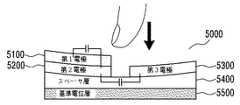
図14gに示されたように、実施形態によるタッチ位置−圧力感知モジュール500
0は、一つの層に形成された第1電極5100、前記第1電極5100が形成された層の
下部層に形成された第2電極5200、前記第2電極5200が形成された層と同じ層に
形成された第3電極5300、前記第2電極5200及び第3電極5300が形成された
層の下部に形成されたスペーサ層5400、及び前記スペーサ層5400の下部に形成さ
れた基準電位層5500を含んでもよい。As shown in FIG. 14g, the touch position-
0 is the same layer as the
この時、第1電極5100及び第2電極5200は、図18bに示された形態のよう
に構成及び配列され、第2電極5200及び第3電極5300は、図18cに示された形
態のように構成及び配列されてもよい。図14hの場合、第1電極5100と第2電極5
200との間の相互静電容量の変化を通じてタッチ位置を検出することができ、第2電極
5200と第3電極5300との間の相互静電容量の変化を通じてタッチ圧力を検出する
ことができる。また、実施形態により、第1電極5100と第3電極5300との間の相
互静電容量の変化を通じてタッチ位置を検出することができ、第1電極5100と第2電
極5200との間の相互静電容量の変化を通じてタッチ圧力を検出することができる。At this time, the
The touch position can be detected through a change in mutual capacitance between the
図14iに示されたように、実施形態によるタッチ位置−圧力感知モジュール500
0は、一つの層に形成された第1電極5100、前記第1電極5100が形成された層の
下部層に形成された第2電極5200、前記第2電極5200が形成された層の下部層に
形成された第3電極5300、前記第3電極5300が形成された層の下部に形成された
スペーサ層5400、及び前記スペーサ層5400の下部に形成された基準電位層550
0を含んでもよい。As shown in FIG. 14i, the touch position-
0 denotes a
0 may be included.
この時、第1電極5100及び第2電極5200は、図18bに示された形態のよう
に構成及び配列されてもよく、第2電極5200及び第3電極5300もまた図18bに
示された形態のように構成及び配列されてもよい。この時、使用者の指のような客体が第
1電極5100及び第2電極5200に近接する場合、指がグランドの役割をして、第1
電極5100及び第2電極5200との間の相互静電容量の変化を通じてタッチ位置を検
出することができ、また、前記客体によってタッチスクリーン130に圧力が加えられる
場合、第2電極5200及び第3電極5300と基準電位層5500との間の距離dが変
わることになり、これにより、第2電極5200と第3電極5300との間の相互静電容
量の変化を通じてタッチ圧力を検出することができる。また、実施形態により、使用者の
指のような客体が第1電極5100及び第2電極5200に近接する場合、指がグランド
の役割をして、第1電極5100及び第2電極5200それぞれの自己静電容量の変化を
通じてタッチ位置を検出することもできる。At this time, the
The touch position can be detected through a change in mutual capacitance between the
図14jに示されたように、実施形態によるタッチ位置−圧力感知モジュール500
0は、一つの層に形成された第1電極5100、前記第1電極5100が形成された層の
下部層に形成された第2電極5200、前記第2電極5200が形成された層の下部に形
成されたスペーサ層5400、及び前記スペーサ層5400の下部層に形成された第3電
極5300を含んでもよい。As shown in FIG. 14j, the touch position-
0 is a
この時、第1電極5100及び第2電極5200は、図18bに示された形態のよう
に構成及び配列されてもよく、第3電極5300は、図18aに示された形態のように構
成されるか、又は、第2電極5200及び第3電極5300が図18bに示された形態の
ように構成及び配列されてもよい。この時、使用者の指のような客体が第1電極5100
及び第2電極5200に近接する場合、指がグランドの役割をして、第1電極5100及
び第2電極5200との間の相互静電容量の変化を通じてタッチ位置を検出することがで
き、また、前記客体によってタッチスクリーン130に圧力が加えられる場合、第2電極
5200と第3電極5300との間の距離dが変わることになり、これにより、第2電極
5200と第3電極5300との間の相互静電容量の変化を通じてタッチ圧力を検出する
ことができる。また、実施形態により、使用者の指のような客体が第1電極5100及び
第2電極5200に近接する場合、指がグランドの役割をして、第1電極5100及び第
2電極5200それぞれの自己静電容量の変化を通じてタッチ位置を検出することができ
る。At this time, the
If the finger is in proximity to the
図14kに示されたように、実施形態によるタッチ位置−圧力感知モジュール500
0は、一つの層に形成された第1電極5100、前記第1電極5100が形成された層の
下部に形成されたスペーサ層5400、及び前記スペーサ層5400の下部層に形成され
た第2電極5200を含んでもよい。As shown in FIG. 14k, the touch position-
この時、第1電極5100及び第2電極5200は、図18bに示された形態のよう
に構成及び配列されてもよい。この時、第1電極5100と第2電極5200との間の相
互静電容量が変化を通じてタッチ位置を検出することができ、また、前記客体によってタ
ッチスクリーン130に圧力が加えられる場合、第1電極5100と第2電極5200と
の間の距離dが変わることになり、これにより、第1電極5100と第2電極5200と
の間の相互静電容量の変化を通じてタッチ圧力を検出することができる。また、第1電極
5100及び第2電極5200は、図18aに示された形態のように構成及び配列されて
もよい。この時、使用者の指のような客体が第1電極5100に近接する場合、指がグラ
ンドの役割をして、第1電極5100の自己静電容量が変わることになり、タッチ位置を
検出することができ、第1電極5100と第2電極5200との間の相互静電容量の変化
を通じてタッチ圧力を検出することができる。At this time, the
図15に示されたように、第3実施形態によるタッチスクリーン130は、タッチ位
置感知モジュール1000、前記タッチ位置感知モジュール1000の下部に配置された
ディスプレイモジュール3000、前記ディスプレイモジュール3000の下部に配置さ
れたタッチ圧力感知モジュール2000、及び前記タッチ圧力感知モジュール2000の
下部に配置された基板4000を含んでもよい。As shown in FIG. 15, the
図10及び図13に示された実施形態によるタッチスクリーン130は、スペーサ層
2400、5400を含むタッチ圧力感知モジュール2000、又は、タッチ位置−圧力
感知モジュール5000がディスプレイモジュール3000の上部に配置されるため、デ
ィスプレイモジュール3000の色の鮮明度、視認性、及び光の透過率が低下することが
ある。したがって、このような問題点が発生することを防止するために、タッチ位置感知
モジュール1000とディスプレイモジュール2000をOCA(Optically
Clear Adhesive)のような接着剤を使用して完全ラミネーション(lam
ination)させ、タッチ圧力感知モジュール2000をディスプレイモジュール3
000の下部に配置することによって、前述した問題点を軽減及び解消することができる
。また、ディスプレイモジュール3000と基板4000との間に既に形成されている間
隙を、タッチ圧力を感知するためのスペーサ層として使用することによって、全体的なタ
ッチスクリーン130の厚さを減少させることができる。The
Complete lamination using an adhesive such as Clear Adhesive
the touch
By disposing it below 000, the above-mentioned problems can be reduced and eliminated. Also, the overall thickness of the
図15に示された実施形態のタッチ位置感知モジュール1000は、図11aないし
図11dに示されたタッチ位置感知モジュールと同一である。The touch
図15に示された実施形態のタッチ圧力感知モジュール2000は、図12aないし
図12fに示されたタッチ圧力感知モジュール、及び図16aないし図16bに示された
タッチ圧力感知モジュールであってもよい。The touch
図16aに示されたように、実施形態によるタッチ圧力感知モジュール2000は、
基準電位層2500、前記基準電位層2500の下部に形成されたスペーサ層2400、
及び前記スペーサ層2400の下部層に形成された第1電極2100を含んでもよい。図
16aの構成及び動作は、単に基準電位層2500と第1電極2100の相対的な位置が
交替したことを除いて図12a及び図12bの構成及び動作と同一なので、以下重複する
説明は省略する。As shown in FIG. 16a, the touch
A
The
図16bに示されたように、実施形態によるタッチ圧力感知モジュール2000は、
基準電位層2500、前記グランドの下部に形成されたスペーサ層2400、前記スペー
サ層2400の下部層に形成された第1電極2100、及び前記第1電極2100が形成
された層の下部層に形成された第2電極2200を含んでもよい。図16bの構成及び動
作は、単に基準電位層2500と第1電極2100及び第2電極2200の相対的な位置
が交替したことを除いて図12c及び図12dの構成及び動作と同一なので、以下重複す
る説明は省略する。この時、第1電極2100と第2電極2200が同一の層に形成され
た場合にも、図12c及び図12dで説明したことと同様にタッチ圧力が感知されてもよ
い。As shown in FIG. 16b, the touch
A
図15においては、タッチ位置感知モジュール1000の下部にディスプレイモジュ
ール3000が配置されたものと説明したが、タッチ位置感知モジュール1000がディ
スプレイモジュール3000の内部に含まれた形態も可能である。また、図15ではディ
スプレイモジュール3000の下部にタッチ圧力感知モジュール2000が配置されたも
のと説明したが、タッチ圧力感知モジュール2000の一部がディスプレイモジュール3
000の内部に含まれた形態も可能である。具体的に、前記タッチ圧力感知モジュール2
000の基準電位層2500がディスプレイモジュール3000の内部に配置され、前記
ディスプレイモジュール3000の下部に電極2100、2200が形成されてもよい。
このように基準電位層2500がディスプレイモジュール3000の内部に配置されれば
、ディスプレイモジュール3000の内部に形成されている間隙を、タッチ圧力を感知す
るためのスペーサ層として使用することによって、全体的なタッチスクリーン130の厚
さを減少させることができる。この時、前記基板4000の上部に電極2100、220
0が形成されてもよい。このように、電極2100、2200が基板4000の上部に形
成されれば、ディスプレイモジュール3000の内部に形成されている間隙だけでなく、
ディスプレイモジュール3000と基板4000との間に形成されている間隙をタッチ圧
力を感知するためのスペーサ層として使用することによって、タッチ圧力を感知する感度
をもう少し高めることができる。In FIG. 15, it has been described that the
A form contained within 000 is also possible. Specifically, the touch
000 reference
If the
0 may be formed. Thus, if the
By using the gap formed between the
図17aは、第4実施形態によるスクリーンの構造図を例示する。図17aに示され
たように、本発明の第4実施形態によるタッチスクリーン130は、ディスプレイモジュ
ール3000内にタッチ位置感知モジュールとタッチ圧力感知モジュールのうち少なくと
も一つを含んでもよい。FIG. 17a illustrates a structural diagram of a screen according to the fourth embodiment. As shown in FIG. 17 a, the
図17b及び17cは、それぞれ第4実施形態によるタッチスクリーンのタッチ圧力
感知及びタッチ位置感知のための構造図である。図17b及び図17cでは、ディスプレ
イモジュール3000としてLCDパネルを例示する。17b and 17c are structural diagrams for touch pressure sensing and touch position sensing of the touch screen according to the fourth embodiment, respectively. 17b and 17c illustrate an LCD panel as the
LCDパネルの場合、ディスプレイモジュール3000は、TFT層3100及びカ
ラーフィルター層3300(color filter layer)を含んでもよい。T
FT層3100は、その真上に位置するTFT基板層3110を含む。カラーフィルター
層3300は、その真下に位置するカラーフィルター基板層3200を含む。ディスプレ
イモジュール3000は、TFT層3100とカラーフィルター層3300との間に液晶
層3600(liquid crystal layer)を含む。この時、TFT基板層
3110は,液晶層3600を駆動するための電場(electric field)を
生成するのに必要な電気的構成要素を含む。特に、TFT基板層3110は、データライ
ン(data line)、ゲートライン(gate line)、TFT、共通(com
mon)電極、及びピクセル電極などを含む多様な層からなってもよい。これらの電気的
構成要素は、制御された電場を生成して液晶層3600に位置した液晶を配向させるよう
に作動することができる。In the case of an LCD panel, the
The
mon) electrodes, pixel electrodes, and the like. These electrical components can operate to generate a controlled electric field to align the liquid crystal located in the
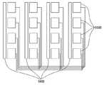
図17bに例示されたように、本発明のディスプレイモジュール3000は、カラー
フィルター基板層3200に配置されたサブフォトスペーサ3500(sub−phot
o spacer)を含んでもよい。これらのサブフォトスペーサ3500は、ロー共通
電極3410と隣接したガード遮蔽電極3420との間の境界点の上に配置されてもよい
。この時、ITOのような伝導性物質層3510がサブフォトスペーサ3500上にパタ
ーニングされてもよい。ここで、フリンジ静電容量C1がロー共通電極3410と伝導性
物質層3510との間に形成され、フリンジ静電容量C2がガード遮蔽電極3420と伝
導性物質層3510との間に形成されてもよい。As illustrated in FIG. 17b, the
o spacer). These sub-photo spacers 3500 may be disposed on a boundary point between the row
図17bに例示されたようなディスプレイモジュール3000がタッチ圧力感知モジ
ュールとして動作する時、外部圧力によってサブフォトスペーサ3500とTFT基板層
3110との間の距離が減少し、これによりロー共通電極3410とガード遮蔽電極34
20との間の静電容量が減少することができる。したがって、図17bにおいて、伝導性
物質層3510が基準電位層の役割を行い、ロー共通電極3410とガード遮蔽電極34
20との間の静電容量の変化を感知することによって、タッチ圧力を感知することができ
る。When the
The capacitance between 20 can be reduced. Therefore, in FIG. 17b, the
By sensing the change in capacitance between 20, the touch pressure can be sensed.
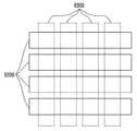
図17cは、LCDパネルが、ディスプレイモジュール3000がタッチ位置感知モ
ジュールとして用いられる場合の構造を例示する。図17cでは、共通電極3730の配
列を例示する。この時、タッチ位置を検出するために、これらの共通電極3730は第1
領域3710と第2領域3720とにグループ付けすることができる。したがって、例え
ば一つの第1領域3710に含まれた共通電極3730は、図18cの第1電極6400
に対応して機能するように操作されてもよく、また、一つの第2領域3720に含まれた
共通電極3730は、図18cの第2電極6500に対応して機能するように操作されて
もよい。すなわち、LCDパネルを動作させるための電気的な構成である共通電極373
0をタッチ位置を検出するのに利用するために共通電極3730はグルーピングされても
よく、このようなグルーピングは、構造的な構成と共に動作操作によって達成され得る。FIG. 17c illustrates the structure of the LCD panel when the
The
The
The
以上で詳しく見たように、図17に例示されたようなディスプレイモジュール300
0は、ディスプレイモジュール3000の電気的構成要素を本来の目的どおりに動作する
ようにすることによって、ディスプレイモジュール3000として機能することができる
。また、ディスプレイモジュール3000は、ディスプレイモジュール3000の電気的
構成要素の少なくとも一部をタッチ圧力感知のために動作するようにすることによって、
タッチ圧力感知モジュールとして機能することができる。また、ディスプレイモジュール
3000は、ディスプレイモジュール3000の電気的構成要素の少なくとも一部をタッ
チ位置感知のために動作するようにすることによって、タッチ位置感知モジュールとして
機能することができる。この時、それぞれの動作モード(mode)は、時分割で動作す
ることができる。すなわち、第1時間区間にディスプレイモジュール3000はディスプ
レイモジュールとして作動し、第2時間区間に圧力感知モジュールとして、及び/又は第
3時間区間に位置感知モジュールとして機能することができる。As seen in detail above, the display module 300 as illustrated in FIG.
0 can function as the
It can function as a touch pressure sensing module. In addition, the
図17b及び図17cにおいては、単に説明のためにタッチ圧力及び位置感知のため
のそれぞれの構造に対して例示するだけであり、ディスプレイモジュール3000のディ
スプレイ動作のための電気的構成要素を操作することによって、ディスプレイモジュール
3000がタッチ圧力及び/又はタッチ位置感知のために用いられ得る場合ならば、第4
実施形態に含まれてもよい。17b and 17c are merely illustrative for the respective structures for touch pressure and position sensing for illustrative purposes and operating the electrical components for display operation of the
It may be included in the embodiment.
図1は、実施形態によるタッチ入力装置100の構造図である。図1を参照すると、
本発明の実施形態によるタッチ入力装置100は、制御器110、タッチスクリーン13
0、及びプロセッサ140を含んでもよい。FIG. 1 is a structural diagram of a
The
0 and
タッチスクリーン130に対するタッチを通じてタッチ入力装置100に対する入力
(input)が行われてもよい。本発明の実施形態によるタッチ入力装置100は、ノ
ートブック(notebook)コンピュータ、PDA(Personal Digit
al Assistant)、及びスマートフォン(smart phone)のような携
帯用電子装置であってもよい。また、本発明の実施形態によるタッチ入力装置100は、
デスクトップ(desktop)コンピュータ、スマートテレビ(smart tele
vision)のような非移動式電子装置であってもよい。An input to the
It may be a portable electronic device such as al Assistant and a smart phone. In addition, the
Desktop computer, smart TV
non-mobile electronic devices such as vision).
本発明の実施形態によるタッチスクリーン130は、使用者が指のような客体でスク
リーンを接触(タッチ)することにより、使用者がコンピューティングシステムを操作す
ることができるようにする。一般的に、タッチスクリーン130はパネル上の接触を認識
し、コンピューティングシステムは、このような接触を解釈することによって、これに従
い演算を行うことができる。The
図1に示されたように、実施形態によるプロセッサ140は、タッチスクリーン13
0に対するタッチの際、タッチの位置を検出することができる。また、プロセッサ140
は、タッチスクリーン130に対するタッチの際、タッチにより発生する静電容量の変化
量を測定することができる。As shown in FIG. 1, the
When touching 0, the position of the touch can be detected. In addition, the
Can measure the amount of change in capacitance generated by the touch when the
実施形態によるタッチ入力装置100は、第1駆動モードと第2駆動モードとで動作
することができる。実施形態によるタッチ入力装置100は、第1駆動モードと第2駆動
モードの何れか一つをデフォルト(default)駆動モードにして操作することがで
きる。例えば、実施形態によるタッチ入力装置100は、第2駆動モードをデフォルトに
して作動することができる。The
第2駆動モードにおいては、実施形態によるタッチ入力装置100が導体のようなタ
ッチ客体でタッチされ、このような客体を通じた静電容量の変化の発生が容易な環境で作
動されてもよい。第2駆動モードにおいて、実施形態によるタッチ入力装置100は、例
えば、プロセッサ140において一般的にタッチ位置を検出する技法により、タッチ客体
を通じたタッチの2次元位置が検出されてもよい。In the second drive mode, the
第1駆動モードでは、実施形態によるタッチ入力装置100が水中(underwa
ter)で作動してもよい。例えば、実施形態によるタッチ入力装置100が、水中にお
いてタッチ客体でタッチされる場合、客体の単純なタッチによる相互静電容量Cmの変化
は一定でないか、もしくは発生が容易でないことがある。第1駆動モードにおいては、タ
ッチスクリーン130に対して客体がタッチの際にタッチ圧力によって発生する静電容量
の変化量を検出することによって、タッチ位置を検出することができる。In the first drive mode, the
ter). For example, when the
したがって、水中で使用者は第1駆動モードを選択してタッチ入力装置100を操作
することができる。実施形態によるタッチ入力装置100において、制御器110は、タ
ッチ入力装置100に対する選択入力を通じて第1駆動モード又は第2駆動モードを動作
させることができる。例えば、タッチ入力装置100においては、物理的なスイッチ又は
ボタンなどを備えて、使用者が必要に応じて第1駆動モードと第2駆動モードに選択が可
能なように具現されてもよい。または、本発明のタッチ入力装置100が備えるタッチス
クリーン130上に、第1駆動モードと第2駆動モードを選択するようにするオプション
がディスプレイされて、使用者の選択入力によって第1駆動モードと第2駆動モードが動
作されてもよい。Therefore, the user can operate the
以下では、第2駆動モードに該当する一般的なタッチの位置(2次元平面上の位置)
を検出する技法をまず説明した後、第1駆動モードに該当するタッチ圧力による静電容量
の変化を検出して、タッチ位置を検出する技法を説明する。In the following, a general touch position corresponding to the second drive mode (position on a two-dimensional plane)
First, a technique for detecting a touch position will be described by detecting a change in capacitance due to a touch pressure corresponding to the first drive mode and detecting a touch position.
プロセッサ140は、タッチスクリーン130のタッチ位置感知モジュール1000
又はタッチ位置−圧力感知モジュール5000を通じてタッチスクリーン130に対する
客体10の近接による静電容量の変化量を測定し、測定された静電容量の変化量からタッ
チ位置を算出することができる。また、実施形態によりプロセッサ140は、タッチスク
リーン130のタッチ位置/圧力を感知することができるディスプレイモジュール300
0を通じて、前述したタッチ位置を算出することができる。The
Alternatively, the amount of change in capacitance due to the proximity of the
Through 0, the touch position described above can be calculated.
図10ないし図18を参照して説明したように、タッチスクリーン130のタッチ位
置を感知するモジュール1000、3000、5000は、複数の駆動電極TX1〜TX
nと複数の受信電極RX1〜RXmを含んでもよい。複数の駆動電極TX1〜TXnと複
数の受信電極RX1〜RXmは直交アレイを構成することができるが、本発明はこれに限
定されず、複数の駆動電極TX1〜TXnと複数の受信電極RX1〜RXmとが、対角線
、同心円、及び3次元ランダム配列などをはじめとする任意の数の次元及びこの応用配列
を有するようにすることができる。ここで、n及びmは、量の整数として互いに同じか、
もしくは別の値を有することができ、実施形態により大きさが変わってもよい。As described with reference to FIGS. 10 to 18, the
n and a plurality of receiving electrodes RX1 to RXm may be included. The plurality of drive electrodes TX1 to TXn and the plurality of reception electrodes RX1 to RXm can form an orthogonal array, but the present invention is not limited to this, and the plurality of drive electrodes TX1 to TXn and the plurality of reception electrodes RX1 to RXm. Can have any number of dimensions, including diagonals, concentric circles, and three-dimensional random arrays, and this application array. Where n and m are the same as integers of quantities,
Alternatively, it may have another value and the size may vary depending on the embodiment.
複数の駆動電極TX1〜TXnと複数の受信電極RX1〜RXmとは、それぞれ互い
に交差するように配列されてもよい。駆動電極TXは、第1軸方向に延びた複数の駆動電
極TX1〜TXnを含み、受信電極RXは、第1軸方向と交差する第2軸方向に延びた複
数の受信電極RX1〜RXmを含んでもよい。The plurality of drive electrodes TX1 to TXn and the plurality of reception electrodes RX1 to RXm may be arranged to cross each other. The drive electrode TX includes a plurality of drive electrodes TX1 to TXn extending in the first axis direction, and the reception electrode RX includes a plurality of reception electrodes RX1 to RXm extending in the second axis direction intersecting the first axis direction. But you can.
実施形態による複数の駆動電極TX1〜TXnと複数の受信電極RX1〜RXmとは
、互いに同一の層に形成されてもよい。例えば、複数の駆動電極TX1〜TXnと複数の
受信電極RX1〜RXmとは、絶縁膜(図示せず)の同一の面に形成されてもよい。また
、複数の駆動電極TX1〜TXnと複数の受信電極RX1〜RXmとは、それぞれ異なる
層に形成されてもよい。例えば、複数の駆動電極TX1〜TXnと複数の受信電極RX1
〜RXmとは、一つの絶縁膜(図示せず)の両面にそれぞれ形成されてもよく、又は、複
数の駆動電極TX1〜TXnは第1絶縁膜(図示せず)の一面に、そして複数の受信電極
RX1〜RXmは前記第1絶縁膜と異なる第2絶縁膜(図示せず)の一面上に形成されて
もよい。The plurality of drive electrodes TX1 to TXn and the plurality of reception electrodes RX1 to RXm according to the embodiment may be formed in the same layer. For example, the plurality of drive electrodes TX1 to TXn and the plurality of reception electrodes RX1 to RXm may be formed on the same surface of an insulating film (not shown). Further, the plurality of drive electrodes TX1 to TXn and the plurality of reception electrodes RX1 to RXm may be formed in different layers. For example, a plurality of drive electrodes TX1 to TXn and a plurality of reception electrodes RX1
˜RXm may be formed on both surfaces of one insulating film (not shown), or the plurality of drive electrodes TX1 to TXn may be formed on one surface of the first insulating film (not shown), and The receiving electrodes RX1 to RXm may be formed on one surface of a second insulating film (not shown) different from the first insulating film.
複数の駆動電極TX1〜TXnと複数の受信電極RX1〜RXmとは、透明伝導性物
質(例えば、ITO(Indium Tin Oxide)又はATO(Antimony
Tin Oxide))などで形成されてもよい。しかし、これは単に例示に過ぎず、駆
動電極TX及び受信電極RXは、他の透明伝導性物質又は銅などの不透明伝導性物質で形
成されてもよい。The plurality of drive electrodes TX1 to TXn and the plurality of reception electrodes RX1 to RXm are made of a transparent conductive material (for example, ITO (Indium Tin Oxide) or ATO (Antimony).
Tin Oxide)) or the like. However, this is merely an example, and the driving electrode TX and the receiving electrode RX may be formed of other transparent conductive materials or opaque conductive materials such as copper.
以上で詳しく見たように、駆動電極TXと受信電極RXの交差地点ごとに所定値の静
電容量Cが生成され、第2駆動モードにおいては、指のような導体である客体がタッチス
クリーン130に近接する場合、このような静電容量の値が変更され得る。このような電
気的特性をプロセッサ140で感知してタッチスクリーン130に対するタッチの有無及
び/又はタッチ位置を感知することができる。例えば、第1軸と第2軸からなる2次元平
面において、タッチスクリーン130に対するタッチの有無及び/又はその位置を感知す
ることができる。As described in detail above, a predetermined capacitance C is generated at each intersection of the drive electrode TX and the reception electrode RX. In the second drive mode, an object that is a conductor such as a finger is touched on the
より具体的に、タッチスクリーン130に対するタッチが生じる時、駆動信号が印加
された駆動電極TXを検出することによって、タッチの第2軸方向の位置を検出すること
ができる。これと同様に、タッチスクリーン130に対するタッチの際に、受信電極RX
を通じて受信された受信信号から静電容量の変化を検出することによって、タッチの第1
軸方向の位置を検出することができる。More specifically, when the touch on the
The first of the touch by detecting a change in capacitance from the received signal received through
An axial position can be detected.
以上においては、実施形態によるタッチスクリーン130に対するタッチの有無及び
/又はタッチの位置を第2駆動モードによって検出する例を説明した。In the above, the example which detected the presence or absence of the touch with respect to the
以上のタッチ位置検出方式は、一般的に導体のような客体がタッチスクリーン130
にタッチすることで変化した相互静電容量Cmの変化量を測定することによって、タッチ
位置を検出するものである。In the touch position detection method described above, an object such as a conductor is generally attached to the
The touch position is detected by measuring the amount of change in the mutual capacitance Cm that has been changed by touching.
以下では、図2aないし図2d及び図3aないし図3dを参照して、本発明の実施形
態によるカメラのリセットプロセスを説明する。Hereinafter, a camera reset process according to an embodiment of the present invention will be described with reference to FIGS. 2a to 2d and FIGS. 3a to 3d.
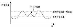
図2aは、タッチスクリーン130に何らのタッチが入力されない時、一般的な環境
におけるタッチスクリーン130で検出される静電容量を示した斜視図であり、図2bは
、図2aのA−A’位置で検出される静電容量を示したグラフであり、図2cは、タッチ
スクリーン130にタッチが入力された時、一般的な環境におけるタッチスクリーン13
0で検出される静電容量を示した斜視図であり、図2dは、図2cのA−A’位置で検出
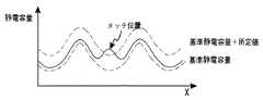
される静電容量を示したグラフである。図3aは、タッチスクリーン130に何らのタッ
チが入力されない時、水中におけるタッチスクリーン130で検出される静電容量を示し
た斜視図であり、図3bは、図3aのB−B’位置で検出される静電容量を示したグラフ
であり、図3cは、タッチスクリーン130にタッチが入力された時、水中におけるタッ
チスクリーン130で検出される静電容量を示した斜視図であり、図3dは、図3cのB
−B’位置で検出される静電容量を示したグラフであり、図3eは、リセットプロセスが
実行された後、図3aのB−B’位置で検出される静電容量を示したグラフであり、図3
fは、リセットプロセスが実行された後、図3cのB−B’位置で検出される静電容量を
示したグラフである。FIG. 2A is a perspective view illustrating capacitance detected by the
FIG. 2D is a graph showing the capacitance detected at the position AA ′ in FIG. 2C. FIG. 3a is a perspective view illustrating capacitance detected by the
FIG. 3e is a graph showing the capacitance detected at the position BB ′ in FIG. 3a after the reset process is executed. Yes, Fig. 3
f is a graph showing the capacitance detected at the BB ′ position in FIG. 3c after the reset process is executed.
水中におけるタッチスクリーン130で検出される静電容量のパターンが、一般的な
環境におけるタッチスクリーン130で検出される静電容量のパターンとは異なって示さ
れる。具体的に、図2a及び図2bに示されたように、タッチスクリーン130に何らの
タッチが入力されない時、一般的な環境におけるタッチスクリーン130で検出される静
電容量は、タッチスクリーン130の位置によって基準静電容量を基準として比較的小さ
い誤差の範囲内に値を有する。したがって、図2c及び図2dに示されたように、タッチ
スクリーン130にタッチが入力されれば、基準静電容量を基準として所定値以上の静電
容量の変化量が発生するようになり、該当位置にタッチが入力されたものと認識するよう
になる。これに反し、図3a及び図3bに示されたように、タッチスクリーン130に何
らのタッチが入力されない時、水中におけるタッチスクリーン130で検出される静電容
量は、タッチスクリーン130の位置によって基準静電容量を基準として比較的大きい誤
差の範囲内の値を有する。したがって、水中で一般的な環境における基準静電容量を基準
としてタッチを認識するようになれば、図3c及び図3dに示されたように、タッチスク
リーン130にタッチが入力されても、基準静電容量を基準として所定値以上の静電容量
の変化量が発生しないか、もしくは、タッチスクリーン130にタッチが入力されなかっ
たのにかかわらず、基準静電容量を基準として所定値以上の静電容量の変化量が発生し、
タッチ位置を認識するのにエラーが発生するようになる。The capacitance pattern detected by the
An error occurs when recognizing the touch position.
したがって、水中ではタッチ入力の有無を判断するための基準静電容量を変更させる
リセットプロセスが必要である。具体的に、図3e及び図3fに示されたように、タッチ
スクリーン130に何らのタッチが入力されない時に示される静電容量パターンに合わせ
て、タッチスクリーン130の各位置に従って基準静電容量を変更すれば、水中でタッチ
スクリーン130にタッチが入力されても、各位置に従って設定された基準静電容量を基
準として静電容量の変化量を計算するようになるので、該当位置にタッチが入力されたも
のと認識するようになる。Therefore, there is a need for a reset process that changes the reference capacitance for determining whether or not there is a touch input underwater. Specifically, as shown in FIGS. 3e and 3f, the reference capacitance is changed according to each position of the
また、図3a及び図3bに示されたように、タッチスクリーン130に何らのタッチ
が入力されない時、水中におけるタッチスクリーン130で検出される静電容量パターン
は、時間に伴って変更され得る。したがって、所定の周期を有してリセットプロセスが繰
り返して実行されるようにすることができる。または、所定の周期を有して静電容量パタ
ーンを検出し、検出された静電容量パターンと以前に検出された静電容量パターンとの誤
差が所定値以上の場合、リセットプロセスが実行されるようにすることができる。Also, as shown in FIGS. 3a and 3b, when no touch is input to the
しかし、このような場合にも、前述した方式に従ってタッチ入力装置100に対する
タッチの位置を明確に検出できない問題点が発生する。However, even in such a case, there arises a problem that the position of the touch on the
タッチ入力装置100が水中(underwater)で操作される場合に、タッチ
入力装置100に対するタッチの際に、客体の単純なタッチによる相互静電容量Cmの変
化が発生しない。タッチ入力装置100が水中で操作される場合、タッチスクリーン13
0に水が接触することになるが、水は導体なので、タッチ入力装置100は、タッチスク
リーン130に無数に多くのタッチが入力されるものと認識するようになるため、水中で
タッチスクリーン130にタッチが入力されても、相互静電容量の変化が発生しない。When the
Although water comes into contact with 0, since water is a conductor, the
したがって、実施形態によるタッチ入力装置100が、水中でタッチスクリーン13
0に対するタッチの有無及びタッチ位置を検出できるタッチ入力装置100を提供する。Therefore, the
Provided is a
以下では、実施形態によるタッチ入力装置100のタッチスクリーン130に対する
タッチの際に、第1駆動モードによりタッチ圧力の大きさによって発生する静電容量の変
化を測定することで、タッチ位置を検出する原理について詳しく説明する。Hereinafter, when the
タッチ時のタッチ圧力によって前記静電容量の変化量の大きさが変わり得る。したが
って、タッチスクリーン130に対するタッチの際、プロセッサ140はタッチ圧力によ
る静電容量の変化量の大きさを測定することができる。ここで、タッチ圧力が小さいほど
静電容量の変化量は小さくてもよく、タッチ圧力が大きいほど静電容量の変化量は大きく
てもよい。The magnitude of the change amount of the capacitance may vary depending on the touch pressure at the time of touch. Accordingly, when the
具体的に、プロセッサ140は、タッチスクリーン130のタッチ圧力感知モジュー
ル2000、タッチ位置−圧力感知モジュール5000又はタッチ圧力を感知することが
できるディスプレイモジュール3000を通じてタッチスクリーン130に加えられる客
体10の圧力による静電容量の変化量を測定し、測定された静電容量の変化量からタッチ
圧力の大きさを算出することができる。In detail, the
図4及び図5は、圧力による静電容量の変化量を説明するための図面である。実施形
態によるプロセッサ140は、静電容量の変化量に基づいてタッチスクリーン130に対
するタッチ位置を計算することができる。4 and 5 are diagrams for explaining the amount of change in capacitance due to pressure. The
具体的に、プロセッサ140は、客体10によりタッチスクリーン130に加えられ
る圧力の大きさによる静電容量の変化量でタッチ位置を計算することができる。例えば、
図4に示されたように、客体10がタッチスクリーン130に圧力を印加することなしに
タッチする場合、静電容量の変化量は0である。図5には、客体10を通じてタッチスク
リーン130に圧力を印加しながらタッチする場合を例示する。このような場合、タッチ
スクリーン130で発生する静電容量が変化し、静電容量の変化量が最も大きい位置を測
定することによってタッチ位置を計算することができる。Specifically, the
As shown in FIG. 4, when the
プロセッサ140は、測定された静電容量の変化量及び/又は測定された静電容量の
変化量から算出されたタッチ位置及びタッチ圧力の大きさのうち、少なくとも何れか一つ
を制御器110に伝送する。この時、制御器110は、プロセッサ140から伝送された
静電容量の変化量を用いてタッチ時間を計算することができる。発明の実施形態により制
御器110はアプリケーションプロセッサ(application processo
r)であってもよい。アプリケーションプロセッサは、携帯用電子装置において命令解釈
、演算、及び制御などの機能を遂行できる処理装置である。例えば、制御器110は、タ
ッチが所定の時間以上維持される場合にだけ、意味のあるタッチと認識するように設定す
ることができる。The
r). An application processor is a processing device that can perform functions such as instruction interpretation, computation, and control in a portable electronic device. For example, the
具体的に、実施形態により意味のあるタッチと認識されるのに必要な静電容量の変化
量の大きさによって、基準値を第1所定値又は第2所定値などに設定することができる。
例えば、プロセッサ140は、図6aに例示されたように、静電容量の変化量が第1所定
値以上維持される8t(1t〜9t)時間の間、客体によるタッチがなされたと判断する
ことができる。また、プロセッサ140は、図6bに例示されたように、静電容量の変化
量が第2所定値以上維持される2t(2t〜4t)時間の間、客体によるタッチがなされ
たと判断することができる。Specifically, the reference value can be set to the first predetermined value, the second predetermined value, or the like according to the amount of change in capacitance necessary to be recognized as a meaningful touch according to the embodiment.
For example, as illustrated in FIG. 6a, the
本発明の実施形態によるタッチスクリーン130を含むタッチ入力装置100は、メ
モリ120をさらに含んでもよい。メモリ120は、前述したような第1所定値、第2所
定値及び/又は意味のあるタッチと認識されるための静電容量の変化量の維持時間などを
格納することができる。以下では、図1及び図7ないし図9を参照して、本発明の実施形
態によるカメラの水中操作方法を説明する。The
図7aないし図7cは、実施形態によるカメラの水中操作方法を説明するためのフロ
ーチャートである。7a to 7c are flowcharts for explaining the underwater operation method of the camera according to the embodiment.
まず、タッチ入力装置1000の第1駆動モードの動作設定が自動である時を説明す
る。First, a case where the operation setting of the first drive mode of the
図7aを参照すると、実施形態によるカメラの水中操作方法は、現在の位置が水中な
のか水中でないのかを判断する段階(S100)、第1駆動モードを動作させる段階(S
200)、カメラを水中で操作する段階(S300)、カメラの終了条件を満たすのかを
判断する段階(S400)、及びカメラを終了する段階(S500)を含んでもよい。Referring to FIG. 7a, the underwater operation method of the camera according to the embodiment determines whether the current position is underwater or not (S100), and operates the first drive mode (S
200), operating the camera in water (S300), determining whether the camera end condition is satisfied (S400), and ending the camera (S500).
制御器110は、現在の位置が水中なのか水中ではないのかを判断する(S100)
。具体的に、タッチスクリーン130は、水と接触すると前記接触した水によってタッチ
入力になされたと判断する。したがって、タッチスクリーン130は、前記水によるタッ
チ入力によって意図しなかった誤動作が起きることがある。制御器110は、現在のタッ
チスクリーン130に入力された条件が所定の条件を満たせば、現在の位置が水中である
と判断することができる。ここで、前記所定の条件は、予め設定されたタッチ数より多く
の数のタッチが持続されるが、所定の時間以上持続する場合であってもよく、図3a及び
図3bに示されたように、タッチスクリーン130において検出される静電容量のパター
ンが所定値以上の大きい誤差範囲を有する場合であってもよい。The
. Specifically, when the
現在の位置が水中ではないと判断されれば、その後の段階が実行されない。 If it is determined that the current position is not underwater, subsequent steps are not performed.
反面、現在の位置が水中と判断されれば、第1駆動モードを動作させる(S200)
。ここで、第1駆動モードが動作すれば、水の接触によって静電容量が変化する状態を何
らのタッチが入力されなかった状態と認識するために、タッチ入力の有無を判断するため
の基準静電容量を変更させるリセットプロセスが実行され、タッチ圧力によってタッチ位
置を検出できるようになる。On the other hand, if the current position is determined to be underwater, the first drive mode is operated (S200).
. Here, if the first drive mode is operated, a reference static value for determining the presence or absence of touch input is recognized in order to recognize that the state in which the capacitance changes due to contact with water is a state in which no touch is input. A reset process for changing the capacitance is performed, and the touch position can be detected by the touch pressure.
このように、現在の位置が水中なのか、そうでないのかを感知して、現在の位置が水
中の場合、水中でタッチ圧力によってタッチ位置を検出できるように自動でリセットプロ
セスが実行されるようにする場合、別途の使用者の操作が必要なくても水中でも端末機を
使用することができる。In this way, if the current position is underwater by sensing whether the current position is underwater, the reset process is automatically performed so that the touch position can be detected by the touch pressure underwater In this case, the terminal can be used even in water without the need for a separate user operation.
タッチ入力装置100の第1駆動モードの動作設定が手動である時を説明する。 A case where the operation setting of the first drive mode of the
図7bを参照すると、実施形態によるカメラの水中操作方法は、第1駆動モードの実
行の有無を選択する段階(S100’)、第1駆動モードを動作させる段階(S200)
、カメラを水中で操作する段階(S300)、カメラの終了条件を満たすのかを判断する
段階(S400)、及びカメラを終了する段階(S500)を含んでもよい。Referring to FIG. 7b, the underwater operation method of the camera according to the embodiment selects the presence or absence of execution of the first drive mode (S100 ′), and operates the first drive mode (S200).
The method may include a step of operating the camera in water (S300), a step of determining whether a camera termination condition is satisfied (S400), and a step of ending the camera (S500).
制御器110は、第1駆動モードの実行の有無を選択できるようにする(S100’
)。具体的に、制御器100は、タッチスクリーン上に第1駆動モードと第2駆動モード
とを選択するようにするオプションをディスプレイすることができる。この時、使用者は
、第1駆動モードを選択することができる。The
). Specifically, the
使用者が第1駆動モードを選択すれば、第1駆動モードを動作させる(S200)。
ここで、第1駆動モードが動作すれば、水の接触によって静電容量が変化する状態を何ら
のタッチが入力されなかった状態と認識するために、タッチ入力の有無を判断するための
基準静電容量を変更させるリセットプロセスが実行され、タッチ圧力によってタッチ位置
を検出することができるようになる。If the user selects the first drive mode, the first drive mode is operated (S200).
Here, if the first drive mode is operated, a reference static value for determining the presence or absence of touch input is recognized in order to recognize that the state in which the capacitance changes due to contact with water is a state in which no touch is input. A reset process for changing the capacitance is performed, and the touch position can be detected by the touch pressure.
このように、現在の位置と関係なく、水中でタッチ圧力によってタッチ位置を検出す
ることができるように手動でリセットプロセスが実行されるようにする場合、端末機を水
中で使用する前に、使用者が直接水中で使用が可能なように端末機を設定することができ
る。In this way, if you want to perform the reset process manually so that the touch position can be detected by the touch pressure underwater, regardless of the current position, use it before using the terminal underwater The terminal can be set so that a person can use it directly underwater.
そして、タッチ入力装置100の第1駆動モードの動作設定が半自動である時を説明
する。A case where the operation setting of the first drive mode of the
図7cを参照すると、実施形態によるカメラの水中操作方法は、現在の位置が水中な
のか水中ではないのかを判断する段階(S100)、第1駆動モードの実行の有無を選択
する段階(S100’)、第1駆動モードを動作させる段階(S200)、カメラを水中
で操作する段階(S300)、カメラの終了条件を満たすのかを判断する段階(S400
)、及びカメラを終了する段階(S500)を含んでもよい。Referring to FIG. 7c, the underwater operation method of the camera according to the embodiment determines whether the current position is underwater or not underwater (S100), and selects whether to execute the first drive mode (S100 ′). ), Operating the first drive mode (S200), operating the camera in water (S300), and determining whether the camera termination condition is satisfied (S400).
) And ending the camera (S500).
制御器110は、現在の位置が水中なのか、水中ではないのかを判断する(S100
)。具体的に、タッチスクリーン130は水と接触すれば、前記接触した水によってタッ
チ入力がなされたと判断する。したがって、タッチスクリーン130は、前記水によるタ
ッチ入力により意図しなかった誤動作が起きることがある。制御器110は、現在のタッ
チスクリーン130に入力された条件が所定の条件を満たせば、現在の位置が水中である
と判断することができる。ここで、前記所定の条件は、予め設定されたタッチ数より多く
数のタッチが持続されるが、所定の時間以上持続する場合であってもよく、図3a及び図
3bに示されたように、タッチセンサーパネル100において検出される静電容量のパタ
ーンが所定値以上の大きい誤差範囲を有する場合であってもよい。The
). Specifically, if the
現在の位置が水中ではないと判断されれば、その後の段階が実行されない。 If it is determined that the current position is not underwater, subsequent steps are not performed.
反面、現在の位置が水中と判断されれば、制御器110は、第1駆動モードの実行の
有無を選択できるようにする(S100’)。具体的に、制御器110は、タッチスクリ
ーン130上に第1駆動モードと第2駆動モードとを選択するようにするオプションをデ
ィスプレイすることができる。この時、使用者は、第1駆動モードを選択することができ
る。On the other hand, if it is determined that the current position is underwater, the
使用者が、第1駆動モードを選択すれば、第1駆動モードを動作させる(S200)
。ここで、第1駆動モードが動作されれば、水の接触によって静電容量が変化する状態を
、何らのタッチが入力されなかった状態と認識するために、タッチ入力の有無を判断する
ための基準静電容量を変更させるリセットプロセスが実行され、タッチ圧力によってタッ
チ位置を検出できるようになる。If the user selects the first drive mode, the first drive mode is operated (S200).
. Here, if the first drive mode is operated, a state in which the capacitance changes due to contact with water is recognized as a state in which no touch is input, so that the presence or absence of touch input is determined. A reset process for changing the reference capacitance is performed, and the touch position can be detected by the touch pressure.
このように、現在の位置が水中なのか、そうでないのかを自動で感知し、現在の位置
が水中の場合、水中でタッチ圧力によってタッチ位置を検出できるように手動でリセット
プロセスが実行されるようにする場合、水中で端末機を使用するのか否かを使用者が水中
で選択可能である。In this way, it will automatically detect whether the current position is underwater or not, and if the current position is underwater, the reset process will be performed manually so that the touch position can be detected by touch pressure underwater In the case where the terminal is to be used, the user can select whether to use the terminal underwater or not.
図8aないし図8dは、水中で操作されるカメラのユーザインタフェースの多様な実
施例を示す。Figures 8a to 8d show various embodiments of a camera user interface operated underwater.
カメラを水中で操作する(S300)。まず、水中で操作されるカメラのユーザイン
タフェースが実行されてもよい。具体的に、タッチスクリーン130上に配置されたアイ
コンをタッチして、水中で操作されるカメラのユーザインタフェースを実行させることが
できる。また、水中で操作されるカメラのユーザインタフェースを実行させるための別途
の物理的なスイッチを動作させて、水中で操作されるカメラのユーザインタフェースを実
行させることができる。The camera is operated underwater (S300). First, a user interface of a camera operated under water may be executed. Specifically, a user interface of a camera operated underwater can be executed by touching an icon arranged on the
ここで、水中で操作されるカメラのユーザインタフェースの実行を、現在の位置が水
中なのか水中ではないのかを判断する段階(S100)、第1駆動モードの実行の有無を
選択する段階(S100’)及び第1駆動モードを動作させる段階(S200)以後のカ
メラを水中で操作する段階(S300)に含めて説明したが、これに限定するのではなく
、現在の位置が水中なのか水中ではないのかを判断する段階(S100)、第1駆動モー
ドの実行の有無を選択する段階(S100’)又は第1駆動モードを動作させる段階(S
200)以前に実行されてもよい。Here, in the execution of the user interface of the camera operated underwater, it is determined whether the current position is underwater or not underwater (S100), and whether to execute the first drive mode is selected (S100 ′). ) And the step of operating the first drive mode (S200) and the subsequent steps (S300) of operating the camera in water have been described. However, the present invention is not limited to this, and the current position is underwater or not underwater. Determining whether or not the first drive mode is executed (S100 ′) or operating the first drive mode (S100).
200) may be performed before.
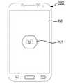
水中で操作されるカメラのユーザインタフェースが実行されれば、図8aに示された
ように、タッチスクリーン130上には、写真を撮影したり動画を撮影できる半透明なシ
ャッターマーク151が配置されてもよい。When the user interface of the camera operated underwater is executed, as shown in FIG. 8a, a
具体的に、タッチスクリーン130の中央部に圧力が加えられる場合、検出されたタ
ッチ位置の誤差が相対的に少ない。反面、タッチスクリーン130の端に圧力が加えられ
る場合、検出されたタッチ位置の誤差が相対的に大きい。したがって、シャッターマーク
151は、タッチスクリーン130の中央に位置することができる。Specifically, when pressure is applied to the center of the
また、タッチ圧力を利用してタッチ位置を検出する場合、一般的なタッチによってタ
ッチ位置を検出する場合に比べて検出されたタッチ位置が不正確であるため、カメラにデ
ィスプレイされるマークの大きさは、一般的なカメラにディスプレイされるマークの大き
さより大きくてもよい。したがって、正確なタッチ位置が検出されなくても、カメラを操
作することができる。Also, when the touch position is detected using the touch pressure, the detected touch position is inaccurate compared to the case where the touch position is detected by a general touch, so the size of the mark displayed on the camera May be larger than the size of a mark displayed on a general camera. Therefore, the camera can be operated even if an accurate touch position is not detected.
使用者は、カメラを用いて撮影する時、シャッターマーク151をタッチすることに
よって撮影することができる。The user can take a picture by touching the
また、図8bに示されたように、タッチスクリーン130上には、半透明なズームイ
ンマーク152及び半透明なズームアウトマーク153が配置されてもよい。Further, as shown in FIG. 8 b, a translucent zoom-in
一例として、使用者は、カメラを用いて撮影する時、ズームインマーク152又はズ
ームアウトマーク153を利用してズームイン又はズームアウトをした後、シャッターマ
ーク151をタッチすることによって撮影することができる。As an example, the user can take a picture by touching the
また、タッチ入力装置100が、タッチ入力装置100の前方を撮影することができ
る前方カメラと後方を撮影することができる後方カメラとを含む場合、図8cに示された
ように、タッチスクリーン130上には前方カメラモード又は後方カメラモードを選択で
きる半透明な切換マーク154が配置されてもよい。Further, when the
一例として、切換マーク154を1回タッチすれば、前方カメラモードが選択されて
使用者の方向を撮影することができ、再び切換マーク154を1回タッチすれば、後方カ
メラモードが選択されて使用者が眺めた方向を撮影することができる。For example, if the switching
そして図8dに示されたように、タッチスクリーン130上には、半透明な表示マー
ク155が配置されてもよい。As shown in FIG. 8d, a
また、写真モード又は動画モードを選択することができる半透明なカメラモードマー
ク156が配置されてもよい。In addition, a translucent
一例として、使用者は、表示マーク155をタッチして撮影された写真又は映像をデ
ィスプレイする表示モードを実行することができる。また、使用者は、カメラモードマー
ク156を1回タッチして動画を撮影することができ、再びカメラモードマーク156を
1回タッチして写真撮影をすることができる。As an example, the user can execute a display mode in which a photograph or video captured by touching the
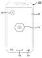
図9は、実施形態によるカメラの終了方法を例示する。 FIG. 9 illustrates a camera termination method according to the embodiment.
カメラの終了条件が満たされるのかを判断(S400)する。具体的に、制御器11
0は、カメラの終了条件が満たされるのかを判断することができる。It is determined whether the camera termination condition is satisfied (S400). Specifically, the controller 11
0 can determine whether the camera termination condition is satisfied.
前記終了条件は、前記終了マーク157にタッチが入力される条件であってもよい。
一例として、図9に示されたように、タッチスクリーン130上には終了マーク157が
配置されてもよく、制御器110は、タッチスクリーン130上に位置した半透明な終了
マーク157のタッチの有無を判断することができる。The end condition may be a condition that a touch is input to the
As an example, as illustrated in FIG. 9, an
また、前記終了条件は、水中で操作されるカメラのユーザインタフェースに一定の時
間以上入力がない条件であってもよい。一例として、制御器110は、カメラが最後に操
作された後、一定の時間(例えば、1分)以上入力がないのかを判断することができる。The termination condition may be a condition in which no input is made for a certain period of time on a user interface of a camera operated in water. As an example, the
そして、前記終了条件は、別途の終了入力手段が実行される条件であってもよい。一
例として、タッチ入力装置100が、別途の終了キー158又は別途のバックキー159
を含む場合、制御器110は、終了キー158又はバックキー159の入力の有無を判断
することができる。The termination condition may be a condition for executing a separate termination input unit. For example, the
The
カメラを終了する(S500)。具体的に、制御器110は、前記終了条件が満たさ
れるのかを判断すれば、カメラを終了することができる。The camera is terminated (S500). Specifically, the
前記マーク151〜157が半透明な場合、前記マーク151〜157がタッチスク
リーン130上にディスプレイされることによって撮影される画面が完全に遮られること
もなく、前記マーク151〜157が完全に見えないこともないので、使用者の立場で便
利に使用することができる。When the
ここで、前記マーク151〜157は半透明なもので説明したが、必ずしもこれに限
定される訳ではなく、前記マーク151〜157は、設定によって不透明又は透明にする
ことができる。また、前記マーク151〜157は、前記設定によって半透明な程度を調
節することができる。Here, the
ここで、タッチスクリーン130上に配置されたマーク151〜157は、互いに第
1所定間隔a以上離隔して配置されてもよい。Here, the
ここで、第1所定間隔aは、一つのマークにタッチが入力される時、検出されたタッ
チ位置の誤差によって意図しなかったマークが選択されない最小限の間隔である。したが
って、図8bに示されたように、シャッターマーク151、ズームインマーク152、及
びズームアウトマーク153は、第1所定間隔a離隔されたので、シャッターマーク15
1に入力されたタッチによって、ズームインマーク152又はズームアウトマーク153
が影響を受けない。Here, the first predetermined interval a is a minimum interval at which an unintended mark is not selected due to an error in the detected touch position when a touch is input to one mark. Therefore, as shown in FIG. 8b, the
The zoom-in
Is not affected.
ここで、タッチスクリーン130上に配置されたマーク151〜157は、タッチス
クリーン130の端から第2所定間隔b以上離隔して配置されてもよい。ここで、第2所
定間隔bは、マークにタッチが入力される時、タッチスクリーン130の端で発生する検
出されたタッチ位置の誤差によって意図しなかったマークが選択されないようにしたり、
意図したマークを選択することができる間隔である。したがって、図8bに示されたよう
に、第2所定間隔bによってズームインマーク152に入力されるタッチをエラーなしに
検出することができる。Here, the
This is the interval at which the intended mark can be selected. Therefore, as shown in FIG. 8b, the touch input to the zoom-in
ここで、図8bでは、第1所定間隔aが第2所定間隔bより大きく示されたが、必ず
しもこれに限定される訳ではなく、第2所定間隔bが第1所定間隔aより大きくてもよく
、第1所定間隔aと第2所定間隔bは互いに同じであってもよい。Here, in FIG. 8b, the first predetermined interval a is shown to be larger than the second predetermined interval b. However, the present invention is not necessarily limited thereto, and even if the second predetermined interval b is larger than the first predetermined interval a. The first predetermined interval a and the second predetermined interval b may be the same.
以上において、実施形態を中心に説明したが、これは単に例示に過ぎず、本発明を限
定する訳ではなく、本発明が属する分野における通常の知識を有する者であれば、本実施
形態の本質的な特徴を外れない範囲で、以上に例示されない様々な変形と応用が可能であ
ることが分かるはずである。例えば、実施形態に具体的に示された各構成要素は、変形し
て実施することができるものである。そして、このような変形と応用に係る相違点は、添
付の特許請求の範囲において規定する本発明の範囲に含まれるものと解釈されるべきであ
る。In the above, the embodiment has been mainly described. However, this is merely an example, and does not limit the present invention. Any person having ordinary knowledge in the field to which the present invention belongs can be used. It should be understood that various modifications and applications not described above are possible without departing from the general characteristics. For example, each component specifically shown in the embodiment can be modified and implemented. Such differences in modification and application should be construed as being included in the scope of the present invention as defined in the appended claims.
100 タッチ入力装置
110 制御器
120 メモリ
130 タッチスクリーン
140 プロセッサDESCRIPTION OF
Claims (16)
Translated fromJapaneseラの水中操作方法において、
水中でタッチ圧力による静電容量の変化量でタッチ位置を検出する第1駆動モードが
動作される段階と、
客体による前記タッチスクリーンに対するタッチを通じてカメラの動作を水中で制御
する段階と、
を含む、カメラの水中操作方法。In an underwater operation method of a camera built in a touch input device including a touch screen, a processor, and a control unit,
A step of operating a first drive mode for detecting a touch position based on a change in capacitance caused by touch pressure in water;
Controlling the operation of the camera in water through touching the touch screen by an object;
Including underwater operation method of the camera.
に記載のカメラの水中操作方法。Determining whether the current location is underwater or not underwater.
The underwater operation method of the camera described in 1.
ラの水中操作方法。The underwater operation method for a camera according to claim 1, further comprising selecting whether or not to execute the first drive mode.
タッチ入力の有無を判断する基準となる基準静電容量を変更させるリセットプロセス
を実行する段階を含む、請求項1ないし3のいずれか1項に記載のカメラの水中操作方法
。The step of operating the first driving mode includes:
The underwater operation method for a camera according to any one of claims 1 to 3, including a step of executing a reset process for changing a reference capacitance serving as a reference for determining the presence or absence of touch input.
所定の周期を有し繰り返して実行される、請求項4に記載のカメラの水中操作方法。The reset process is:
The underwater operation method for a camera according to claim 4, wherein the camera is repeatedly executed with a predetermined period.
所定の周期を有し前記タッチスクリーンで静電容量パターンを検出し、前記静電容量
パターンと以前に検出された静電容量パターンとの誤差が所定値以上である場合、実行さ
れる、請求項4に記載のカメラの水中操作方法。The reset process is:
The capacitance pattern is detected by the touch screen having a predetermined period, and is executed when an error between the capacitance pattern and the previously detected capacitance pattern is equal to or greater than a predetermined value. 4. The underwater operation method of the camera according to 4.
前記タッチスクリーン上に配置されたシャッターマークをタッチして撮影する段階を
含む、請求項1に記載のカメラの水中操作方法。The step of controlling the operation of the camera underwater includes
The underwater operation method of a camera according to claim 1, comprising a step of shooting by touching a shutter mark arranged on the touch screen.
前記タッチスクリーン上に配置されたズームインマークをタッチしてズームインし、
前記タッチスクリーン上に配置されたズームアウトマークをタッチしてズームアウトする
段階を含む、請求項7に記載のカメラの水中操作方法。The step of controlling the operation of the camera underwater includes
Touch the zoom-in mark placed on the touch screen to zoom in,
The underwater operation method of a camera according to claim 7, comprising the step of zooming out by touching a zoom-out mark arranged on the touch screen.
前記タッチスクリーン上に配置された切換マークをタッチして前方カメラモード又は
後方カメラモードを選択する段階を含む、請求項7に記載のカメラの水中操作方法。The step of controlling the operation of the camera underwater includes
The underwater operation method for a camera according to claim 7, comprising a step of selecting a front camera mode or a rear camera mode by touching a switching mark arranged on the touch screen.
前記タッチスクリーン上に配置された表示マークをタッチして撮影された映像をディ
スプレイする表示モードを実行する段階を含む、請求項7に記載のカメラの水中操作方法
。The step of controlling the operation of the camera underwater includes
The underwater operation method for a camera according to claim 7, further comprising: executing a display mode in which an image captured by touching a display mark disposed on the touch screen is displayed.
前記タッチスクリーン上に配置されたカメラモードマークをタッチして写真モード又
は動画モードを選択する段階を含む、請求項7に記載のカメラの水中操作方法。The step of controlling the operation of the camera underwater includes
The underwater operation method of a camera according to claim 7, comprising the step of selecting a photo mode or a moving image mode by touching a camera mode mark arranged on the touch screen.
カメラを終了する段階と、
をさらに含む、請求項1に記載のカメラの水中操作方法。Determining whether camera termination conditions are met,
Exiting the camera,
The underwater operation method for a camera according to claim 1, further comprising:
前記タッチスクリーン上に配置された終了マークのタッチの有無を判断する段階を含
む、請求項12に記載のカメラ水中操作方法。The stage to determine if the camera termination condition is met
The camera underwater operation method according to claim 12, comprising the step of determining whether or not the end mark arranged on the touch screen is touched.
13のいずれか1項に記載のカメラの水中操作方法。The underwater operation method for a camera according to claim 7, wherein the mark disposed on the touch screen is translucent.
、請求項8ないし11及び13のいずれか1項に記載のカメラの水中操作方法。The underwater operation method for a camera according to any one of claims 8 to 11 and 13, wherein the marks arranged on the touch screen are spaced apart from each other by a first predetermined interval or more.
定間隔以上離隔した、請求項7ないし11及び13に記載のカメラの水中操作方法。14. The underwater operation method for a camera according to claim 7, wherein the mark arranged on the touch screen is separated from an end of the touch screen by a second predetermined interval or more.
Applications Claiming Priority (14)
| Application Number | Priority Date | Filing Date | Title |
|---|---|---|---|
| KR1020140034169AKR101618653B1 (en) | 2014-03-24 | 2014-03-24 | Touch input device and touch detecting method |
| KR10-2014-0034169 | 2014-03-24 | ||
| KR1020140048335AKR101752315B1 (en) | 2014-04-22 | 2014-04-22 | Underwater control method of camera |
| KR10-2014-0048335 | 2014-04-22 | ||
| KR10-2014-0055732 | 2014-05-09 | ||
| KR1020140055732AKR101581791B1 (en) | 2014-05-09 | 2014-05-09 | Touch input device and touch detecting method |
| KR10-2014-0098917 | 2014-08-01 | ||
| KR1020140098917AKR101681305B1 (en) | 2014-08-01 | 2014-08-01 | Touch input device |
| KR10-2014-0124920 | 2014-09-19 | ||
| KR1020140124920AKR101712346B1 (en) | 2014-09-19 | 2014-09-19 | Touch input device |
| KR1020140145022AKR20160048424A (en) | 2014-10-24 | 2014-10-24 | Touch input device |
| KR10-2014-0145022 | 2014-10-24 | ||
| KR1020140186352AKR101693337B1 (en) | 2014-12-22 | 2014-12-22 | Touch input device |
| KR10-2014-0186352 | 2014-12-22 |
Related Parent Applications (1)
| Application Number | Title | Priority Date | Filing Date |
|---|---|---|---|
| JP2015060023ADivisionJP6326001B2 (en) | 2014-03-24 | 2015-03-23 | Underwater operation of the camera |
Publications (1)
| Publication Number | Publication Date |
|---|---|
| JP2017174447Atrue JP2017174447A (en) | 2017-09-28 |
Family
ID=54142098
Family Applications (2)
| Application Number | Title | Priority Date | Filing Date |
|---|---|---|---|
| JP2015060023AActiveJP6326001B2 (en) | 2014-03-24 | 2015-03-23 | Underwater operation of the camera |
| JP2017093158APendingJP2017174447A (en) | 2014-03-24 | 2017-05-09 | Underwater camera operating method |
Family Applications Before (1)
| Application Number | Title | Priority Date | Filing Date |
|---|---|---|---|
| JP2015060023AActiveJP6326001B2 (en) | 2014-03-24 | 2015-03-23 | Underwater operation of the camera |
Country Status (2)
| Country | Link |
|---|---|
| US (2) | US10104270B2 (en) |
| JP (2) | JP6326001B2 (en) |
Cited By (1)
| Publication number | Priority date | Publication date | Assignee | Title |
|---|---|---|---|---|
| JP2019220162A (en)* | 2018-06-06 | 2019-12-26 | ケンブリッジ タッチ テクノロジーズ リミテッドCambridge Touch Technologies Limited | Pressure sensing device and method |
Families Citing this family (16)
| Publication number | Priority date | Publication date | Assignee | Title |
|---|---|---|---|---|
| JP6284839B2 (en)* | 2014-06-26 | 2018-02-28 | 株式会社東海理化電機製作所 | Touch input device |
| TWI575414B (en)* | 2015-04-01 | 2017-03-21 | 晨星半導體股份有限公司 | Mode distinguishing method, touch-point locating method and touch control circuit |
| JP6062484B2 (en)* | 2015-05-12 | 2017-01-18 | 京セラ株式会社 | Electronic device, control method, and control program |
| US10365811B2 (en) | 2015-09-15 | 2019-07-30 | Verizon Patent And Licensing Inc. | Home screen for wearable devices |
| JP6369430B2 (en) | 2015-09-18 | 2018-08-08 | マツダ株式会社 | Exhaust system for turbocharged engine |
| CN205121517U (en)* | 2015-10-29 | 2016-03-30 | 深圳市汇顶科技股份有限公司 | Pressure detection structure and terminal equipment |
| JP2018022225A (en)* | 2016-08-01 | 2018-02-08 | 株式会社ジャパンディスプレイ | Pressure detection device and display device including the same |
| KR102562612B1 (en) | 2016-08-05 | 2023-08-03 | 삼성전자주식회사 | Electronic Device for Including Display Equipped with Force Sensor |
| CN106354261B (en)* | 2016-09-05 | 2019-07-09 | 广东小天才科技有限公司 | Method and device for switching input mode of mobile equipment, and mobile equipment |
| KR102748020B1 (en)* | 2017-02-15 | 2024-12-31 | 삼성전자주식회사 | Electronic device and method for determining underwater shooting |
| JP6829776B2 (en)* | 2017-03-29 | 2021-02-10 | アルプスアルパイン株式会社 | Water rejection on capacitive door handles |
| US10976278B2 (en) | 2017-08-31 | 2021-04-13 | Apple Inc. | Modifying functionality of an electronic device during a moisture exposure event |
| KR102452620B1 (en)* | 2017-09-29 | 2022-10-07 | 삼성전자주식회사 | Apparatus and method for detecting touch |
| CN110174972B (en)* | 2019-06-04 | 2022-10-18 | 业成科技(成都)有限公司 | Touch system, operation method and non-transitory computer readable recording medium |
| TWI711961B (en) | 2019-08-14 | 2020-12-01 | 仁寶電腦工業股份有限公司 | Control method for touch device |
| JP2022035172A (en) | 2020-08-20 | 2022-03-04 | 株式会社ジャパンディスプレイ | Display, detector and clock |
Citations (11)
| Publication number | Priority date | Publication date | Assignee | Title |
|---|---|---|---|---|
| JP2008236035A (en)* | 2007-03-16 | 2008-10-02 | Casio Comput Co Ltd | Image display device |
| JP2009276821A (en)* | 2008-05-12 | 2009-11-26 | Casio Hitachi Mobile Communications Co Ltd | Touch panel device, display device, and terminal device |
| JP2010033538A (en)* | 2008-06-30 | 2010-02-12 | Nintendo Co Ltd | Information processing apparatus and information processing program |
| JP2010122795A (en)* | 2008-11-18 | 2010-06-03 | Fujifilm Corp | Electronic apparatus and method of controlling the same |
| JP2012027701A (en)* | 2010-07-23 | 2012-02-09 | Sony Corp | User interface device and user interface method |
| JP2012256153A (en)* | 2011-06-08 | 2012-12-27 | Panasonic Corp | Character input device and portable terminal |
| JP2013114326A (en)* | 2011-11-25 | 2013-06-10 | Kyocera Display Corp | Touch panel device |
| JP2013117891A (en)* | 2011-12-05 | 2013-06-13 | Sanyo Electric Co Ltd | User interface device |
| JP2013186501A (en)* | 2012-03-05 | 2013-09-19 | Ntt Docomo Inc | Touch panel structure and position detection system selection method |
| JP2013222283A (en)* | 2012-04-16 | 2013-10-28 | Sharp Corp | Electronic device, and method and program for controlling the same |
| JP2014013398A (en)* | 2013-08-06 | 2014-01-23 | Sony Corp | Imaging apparatus and method, and program |
Family Cites Families (13)
| Publication number | Priority date | Publication date | Assignee | Title |
|---|---|---|---|---|
| JPS5353996A (en) | 1976-10-27 | 1978-05-16 | Yasuo Wakabayashi | Photoelectric numeric indicator |
| JPS6251058A (en) | 1985-08-30 | 1987-03-05 | Hitachi Ltd | Mode discrimination circuit |
| WO2005108946A1 (en) | 2004-05-12 | 2005-11-17 | Toyo Communication Equipment Co., Ltd. | Pressure sensor |
| JP2005328224A (en) | 2004-05-13 | 2005-11-24 | Fuji Photo Film Co Ltd | Digital camera |
| KR101025613B1 (en) | 2008-08-27 | 2011-03-30 | 한국표준과학연구원 | Touch input structure for measuring contact position and pressing force by capacitive multi-touch |
| EP2494430B1 (en)* | 2009-10-27 | 2019-06-26 | Microsoft Technology Licensing, LLC | Projected capacitive touch sensing |
| KR101288740B1 (en)* | 2010-07-01 | 2013-07-23 | 주식회사 팬택 | Touch screen device for detecting noise and control method using the same |
| US20120256867A1 (en)* | 2011-04-09 | 2012-10-11 | Annacone William R | Underwater touchscreen system |
| JP2013179536A (en) | 2012-02-29 | 2013-09-09 | Nec Casio Mobile Communications Ltd | Electronic apparatus and control method therefor |
| EP2821897B1 (en)* | 2013-07-04 | 2019-08-21 | Sony Corporation | Finger detection on touch screens for mobile devices |
| US9134866B2 (en)* | 2013-07-18 | 2015-09-15 | Sony Corporation | Dry/wet touch screen |
| KR102065411B1 (en)* | 2013-09-04 | 2020-01-13 | 엘지전자 주식회사 | Mobile terminal and controlling method thereof |
| US8982097B1 (en)* | 2013-12-02 | 2015-03-17 | Cypress Semiconductor Corporation | Water rejection and wet finger tracking algorithms for truetouch panels and self capacitance touch sensors |
- 2015
- 2015-03-20USUS14/663,551patent/US10104270B2/enactiveActive
- 2015-03-23JPJP2015060023Apatent/JP6326001B2/enactiveActive
- 2017
- 2017-05-09JPJP2017093158Apatent/JP2017174447A/enactivePending
- 2018
- 2018-09-04USUS16/121,438patent/US10404898B2/enactiveActive
Patent Citations (11)
| Publication number | Priority date | Publication date | Assignee | Title |
|---|---|---|---|---|
| JP2008236035A (en)* | 2007-03-16 | 2008-10-02 | Casio Comput Co Ltd | Image display device |
| JP2009276821A (en)* | 2008-05-12 | 2009-11-26 | Casio Hitachi Mobile Communications Co Ltd | Touch panel device, display device, and terminal device |
| JP2010033538A (en)* | 2008-06-30 | 2010-02-12 | Nintendo Co Ltd | Information processing apparatus and information processing program |
| JP2010122795A (en)* | 2008-11-18 | 2010-06-03 | Fujifilm Corp | Electronic apparatus and method of controlling the same |
| JP2012027701A (en)* | 2010-07-23 | 2012-02-09 | Sony Corp | User interface device and user interface method |
| JP2012256153A (en)* | 2011-06-08 | 2012-12-27 | Panasonic Corp | Character input device and portable terminal |
| JP2013114326A (en)* | 2011-11-25 | 2013-06-10 | Kyocera Display Corp | Touch panel device |
| JP2013117891A (en)* | 2011-12-05 | 2013-06-13 | Sanyo Electric Co Ltd | User interface device |
| JP2013186501A (en)* | 2012-03-05 | 2013-09-19 | Ntt Docomo Inc | Touch panel structure and position detection system selection method |
| JP2013222283A (en)* | 2012-04-16 | 2013-10-28 | Sharp Corp | Electronic device, and method and program for controlling the same |
| JP2014013398A (en)* | 2013-08-06 | 2014-01-23 | Sony Corp | Imaging apparatus and method, and program |
Cited By (2)
| Publication number | Priority date | Publication date | Assignee | Title |
|---|---|---|---|---|
| JP2019220162A (en)* | 2018-06-06 | 2019-12-26 | ケンブリッジ タッチ テクノロジーズ リミテッドCambridge Touch Technologies Limited | Pressure sensing device and method |
| JP7252832B2 (en) | 2018-06-06 | 2023-04-05 | ケンブリッジ タッチ テクノロジーズ リミテッド | Pressure sensing device and method |
Also Published As
| Publication number | Publication date |
|---|---|
| US20180376040A1 (en) | 2018-12-27 |
| US20150268782A1 (en) | 2015-09-24 |
| US10404898B2 (en) | 2019-09-03 |
| JP6326001B2 (en) | 2018-05-16 |
| JP2015185171A (en) | 2015-10-22 |
| US10104270B2 (en) | 2018-10-16 |
Similar Documents
| Publication | Publication Date | Title |
|---|---|---|
| JP6326001B2 (en) | Underwater operation of the camera | |
| EP3054381B1 (en) | Touch type distinguishing method and touch input device performing the same | |
| US10268322B2 (en) | Method for temporarily manipulating operation of object in accordance with touch pressure or touch area and terminal thereof | |
| JP6247651B2 (en) | Menu operation method and menu operation device including touch input device for performing the same | |
| US10031604B2 (en) | Control method of virtual touchpad and terminal performing the same | |
| US9886116B2 (en) | Gesture and touch input detection through force sensing | |
| KR102172819B1 (en) | Device and method for localized force and proximity sensing | |
| JP6577967B2 (en) | Method of adjusting moving direction of display object and terminal | |
| JP6062913B2 (en) | Object operation control system and method based on touch | |
| US10198123B2 (en) | Mitigating noise in capacitive sensor | |
| KR20100136289A (en) | Display Control Method of Mobile Terminal | |
| KR101933049B1 (en) | Underwater control method of camera | |
| KR101752315B1 (en) | Underwater control method of camera | |
| JP6401220B2 (en) | Object operation control system and method based on touch | |
| KR102124619B1 (en) | Touch type distinguishing method and touch input device performing the same |
Legal Events
| Date | Code | Title | Description |
|---|---|---|---|
| A521 | Request for written amendment filed | Free format text:JAPANESE INTERMEDIATE CODE: A523 Effective date:20170629 | |
| A621 | Written request for application examination | Free format text:JAPANESE INTERMEDIATE CODE: A621 Effective date:20170629 | |
| A131 | Notification of reasons for refusal | Free format text:JAPANESE INTERMEDIATE CODE: A131 Effective date:20180821 | |
| A601 | Written request for extension of time | Free format text:JAPANESE INTERMEDIATE CODE: A601 Effective date:20181120 | |
| A601 | Written request for extension of time | Free format text:JAPANESE INTERMEDIATE CODE: A601 Effective date:20190118 | |
| A02 | Decision of refusal | Free format text:JAPANESE INTERMEDIATE CODE: A02 Effective date:20190416 |