JP2017173327A - Positioning method and positioning device using satellite positioning system - Google Patents
Positioning method and positioning device using satellite positioning systemDownload PDFInfo
- Publication number
- JP2017173327A JP2017173327AJP2017056762AJP2017056762AJP2017173327AJP 2017173327 AJP2017173327 AJP 2017173327AJP 2017056762 AJP2017056762 AJP 2017056762AJP 2017056762 AJP2017056762 AJP 2017056762AJP 2017173327 AJP2017173327 AJP 2017173327A
- Authority
- JP
- Japan
- Prior art keywords
- satellite
- delay amount
- positioning
- mobile station
- station
- Prior art date
- Legal status (The legal status is an assumption and is not a legal conclusion. Google has not performed a legal analysis and makes no representation as to the accuracy of the status listed.)
- Granted
Links
Images


Classifications
- G—PHYSICS
- G01—MEASURING; TESTING
- G01S—RADIO DIRECTION-FINDING; RADIO NAVIGATION; DETERMINING DISTANCE OR VELOCITY BY USE OF RADIO WAVES; LOCATING OR PRESENCE-DETECTING BY USE OF THE REFLECTION OR RERADIATION OF RADIO WAVES; ANALOGOUS ARRANGEMENTS USING OTHER WAVES
- G01S19/00—Satellite radio beacon positioning systems; Determining position, velocity or attitude using signals transmitted by such systems
- G01S19/38—Determining a navigation solution using signals transmitted by a satellite radio beacon positioning system
- G01S19/39—Determining a navigation solution using signals transmitted by a satellite radio beacon positioning system the satellite radio beacon positioning system transmitting time-stamped messages, e.g. GPS [Global Positioning System], GLONASS [Global Orbiting Navigation Satellite System] or GALILEO
- G01S19/42—Determining position
- G01S19/43—Determining position using carrier phase measurements, e.g. kinematic positioning; using long or short baseline interferometry
- G01S19/44—Carrier phase ambiguity resolution; Floating ambiguity; LAMBDA [Least-squares AMBiguity Decorrelation Adjustment] method
- G—PHYSICS
- G01—MEASURING; TESTING
- G01S—RADIO DIRECTION-FINDING; RADIO NAVIGATION; DETERMINING DISTANCE OR VELOCITY BY USE OF RADIO WAVES; LOCATING OR PRESENCE-DETECTING BY USE OF THE REFLECTION OR RERADIATION OF RADIO WAVES; ANALOGOUS ARRANGEMENTS USING OTHER WAVES
- G01S19/00—Satellite radio beacon positioning systems; Determining position, velocity or attitude using signals transmitted by such systems
- G01S19/01—Satellite radio beacon positioning systems transmitting time-stamped messages, e.g. GPS [Global Positioning System], GLONASS [Global Orbiting Navigation Satellite System] or GALILEO
- G01S19/03—Cooperating elements; Interaction or communication between different cooperating elements or between cooperating elements and receivers
- G01S19/07—Cooperating elements; Interaction or communication between different cooperating elements or between cooperating elements and receivers providing data for correcting measured positioning data, e.g. DGPS [differential GPS] or ionosphere corrections
- G01S19/072—Ionosphere corrections
Landscapes
- Engineering & Computer Science (AREA)
- Radar, Positioning & Navigation (AREA)
- Remote Sensing (AREA)
- Computer Networks & Wireless Communication (AREA)
- Physics & Mathematics (AREA)
- General Physics & Mathematics (AREA)
- Position Fixing By Use Of Radio Waves (AREA)
Abstract
Translated fromJapaneseDescription
Translated fromJapanese本発明は、衛星測位システムを用いた測位方法および測位装置に関するものである。 The present invention relates to a positioning method and a positioning device using a satellite positioning system.
近年、地球上での三次元位置を特定するのに全地球衛星測位システム(GNSS:Global Navigation Satellite System)が用いられている。そして、このGNSSにおいては、精度が低い単独測位と、精度が良い相対測位とがあるが、最近、単独測位においても、精度が良い方式が提案されている。 In recent years, a Global Navigation Satellite System (GNSS) has been used to specify a three-dimensional position on the earth. In this GNSS, there are independent positioning with low accuracy and relative positioning with high accuracy. Recently, a method with high accuracy has also been proposed for independent positioning.
この測位方式は、GNSSで用いられる信号搬送用の2つの電波、すなわち二周波を用いることにより、衛星と観測局すなわち移動局との距離を精度良く計測し得るようにしたものであるが、二周波を用いた測位装置は高価なものになるという欠点があった。このため、一周波を用いて単独測位を行い得る測位方法が提案されている。この測位方法は、RTK測位方式(Real Time Kinematic)をベースにしたものであり、移動局の近傍に基準局を必要とするものであった(例えば、特許文献1参照)。 This positioning method can measure the distance between a satellite and an observation station, that is, a mobile station with high accuracy by using two radio waves for signal transmission used in GNSS, that is, two frequencies. The positioning device using the frequency has a drawback of becoming expensive. For this reason, a positioning method capable of performing independent positioning using one frequency has been proposed. This positioning method is based on the RTK positioning method (Real Time Kinematic) and requires a reference station in the vicinity of the mobile station (see, for example, Patent Document 1).
ところで、RTK測位方式の場合、基準局と移動局との距離が数キロメートルを超えると、基準局と移動局との間の電離層による遅延誤差、対流圏による遅延誤差が大きくなり、アンビギュイティを求めることができなくなる。つまり、センチメートル精度の測位ができなくなる。一般的には、距離が5キロメートルを超えると、一周波によるRTK測位方式では、アンビギュイティを解くことができなくなる。すなわち、アンビギュイティの決定を必要とする測位方式では、高価な二周波GNSS受信機が必要になるという問題がある。 By the way, in the case of the RTK positioning method, when the distance between the reference station and the mobile station exceeds several kilometers, the delay error due to the ionosphere between the reference station and the mobile station and the delay error due to the troposphere become large, and ambiguity can be obtained. become unable. In other words, positioning with centimeter accuracy becomes impossible. Generally, when the distance exceeds 5 kilometers, the ambiguity cannot be solved by the RTK positioning method using one frequency. That is, there is a problem that an expensive dual-frequency GNSS receiver is required in a positioning method that requires determination of ambiguity.
そこで、本発明は、移動局が基準局から離れた場合でも、安価な一周波受信機を用いて精度良く測位し得る衛星測位システムを用いた測位方法および測位装置を提供することを目的とする。 Therefore, an object of the present invention is to provide a positioning method and a positioning apparatus using a satellite positioning system that can perform positioning with high accuracy using an inexpensive single-frequency receiver even when a mobile station is away from a reference station.
上記目的を達成するため、本発明の衛星測位システムを用いた測位方法は、衛星測位システムからの測位電波および基準局側からの補正情報を受信するとともに上記測位電波の一周波を用いて移動局の測位を行う方法であって、
コードによる擬似距離観測式および搬送波による位相距離観測式を用い、
上記擬似距離観測式を、衛星時計誤差、受信局時計誤差、電離層遅延量および対流圏遅延量を用いて、測位電波を受信する基準局または移動局である受信局と衛星との間の距離と、上記受信局および衛星におけるコードバイアスで表したものとし、
上記位相距離観測式を、衛星時計誤差、受信局時計誤差、電離層遅延量、対流圏遅延量および搬送波位相アンビギュイティ用いて、測位電波を受信する受信局と衛星との間の距離と、上記受信局および衛星における位相バイアスで表したものとし、
上記基準局側にて、衛星時計誤差、一周波の衛星コードバイアスおよび衛星位相バイアス、電離層遅延量並びに対流圏遅延量の各パラメータを推定し、
上記移動局にて、上記推定された各パラメータ並びに移動局での電離層遅延量および対流圏遅延量を用いて、コードによる擬似距離、時計誤差に基づく距離、少なくとも一周波の移動局位相バイアス、および搬送波位相アンビギュイティを推定した後、上記搬送波位相アンビギュイティを決定して衛星と移動局との間の距離を求め、ここで上記移動局での各遅延量は、基準局側から移動局までの距離と、当該基準局側での遅延量とに基づいて内挿法により求める方法である。In order to achieve the above object, a positioning method using the satellite positioning system of the present invention receives a positioning radio wave from the satellite positioning system and correction information from the reference station side and uses one frequency of the positioning radio wave. A method for positioning,
Using the pseudorange observation formula by code and the phase distance observation formula by carrier wave,
Using the above pseudorange observation formula, satellite clock error, receiving station clock error, ionospheric delay amount and tropospheric delay amount, the distance between the receiving station and the satellite that is a reference station or mobile station that receives positioning radio waves, and the above It is expressed as a code bias at the receiving station and satellite.
Using the above phase distance observation formula, satellite clock error, receiving station clock error, ionospheric delay amount, tropospheric delay amount and carrier phase ambiguity, the distance between the receiving station receiving the positioning radio wave and the satellite, and the above reception It is expressed in terms of the phase bias at the station and satellite,
Estimate each parameter of satellite clock error, single frequency satellite code bias and satellite phase bias, ionospheric delay amount and tropospheric delay amount on the reference station side,
In the mobile station, using the estimated parameters and the ionospheric delay amount and tropospheric delay amount in the mobile station, a pseudo-range by code, a distance based on a clock error, a mobile station phase bias of at least one frequency, and a carrier wave After estimating the phase ambiguity, the carrier phase ambiguity is determined to determine the distance between the satellite and the mobile station. Here, each delay amount at the mobile station is determined from the reference station side to the mobile station. This is a method of obtaining by interpolation based on the distance and the delay amount on the reference station side.
また、本発明の衛星測位システムを用いた測位装置は、上記衛星測位システムを用いた測位方法を移動局にて実行する装置であって、
衛星からの測位電波を受信してコードによる擬似距離および搬送波による位相距離を観測するように構成された距離観測ユニットと、
基準局側から送られる衛星軌道、衛星時計誤差、並びに基準局側での電離層遅延量および対流圏遅延量などの補正情報を取得するように構成された補正情報取得ユニットと、
上記補正情報取得ユニットからの補正情報を入力として受信して移動局での電離層遅延量および対流圏遅延量を算出するように構成された遅延量算出ユニットと、
上記擬似距離、位相距離、電離層遅延量および対流圏遅延量を入力として受信して移動局の位置および一重差アンビギュイティを推定するように構成された位置等推定ユニットと、
上記位置等推定ユニットにて推定された一重差アンビギュイティを入力として受信して一重差アンビギュイティを決定するように構成されたアンビギュイティ決定ユニットと、
上記アンビギュイティ決定ユニットにて決定された一重差アンビギュイティを入力として受信して移動局の位置を決定するように構成された位置決定ユニットとを具備し、
且つ上記測位を行う際に、コードによる擬似距離観測式および搬送波による位相距離観測式を用いるとともに、
上記擬似距離観測式を、衛星時計誤差、受信局時計誤差、電離層遅延量および対流圏遅延量を用いて、測位電波を受信する基準局または移動局である受信局と衛星との間の距離と、上記受信局および衛星における一周波のコードバイアスで表したものとし、
上記位相距離観測式を、衛星時計誤差、受信局時計誤差、電離層遅延量、対流圏遅延量および搬送波位相アンビギュイティを用いて、測位電波を受信する受信局と衛星との間の距離と、上記受信局および衛星における一周波の位相バイアスで表したものとするものである。A positioning device using the satellite positioning system of the present invention is a device that executes a positioning method using the satellite positioning system in a mobile station,
A distance observation unit configured to receive a positioning radio wave from a satellite and observe a pseudo distance by a code and a phase distance by a carrier;
A correction information acquisition unit configured to acquire correction information such as satellite orbit, satellite clock error sent from the reference station side, and ionospheric delay amount and tropospheric delay amount on the reference station side;
A delay amount calculation unit configured to receive the correction information from the correction information acquisition unit as an input and calculate an ionospheric delay amount and a tropospheric delay amount in the mobile station;
A position estimation unit configured to receive the pseudorange, phase distance, ionospheric delay amount and tropospheric delay amount as input to estimate the position and single difference ambiguity of the mobile station;
An ambiguity determining unit configured to receive a single difference ambiguity estimated by the position estimation unit as an input and determine a single difference ambiguity;
A position determining unit configured to receive a single difference ambiguity determined by the ambiguity determining unit as an input and determine a position of the mobile station; and
And when performing the above positioning, while using the pseudo distance observation formula by the code and the phase distance observation formula by the carrier wave,
Using the above pseudorange observation formula, satellite clock error, receiving station clock error, ionospheric delay amount and tropospheric delay amount, the distance between the receiving station and the satellite that is a reference station or mobile station that receives positioning radio waves, and the above Expressed as a single-frequency code bias at the receiving station and satellite,
Using the phase distance observation formula, satellite clock error, receiving station clock error, ionospheric delay amount, tropospheric delay amount and carrier phase ambiguity, the distance between the receiving station that receives the positioning radio wave and the satellite, and the above This is expressed by a phase bias of one frequency in the receiving station and the satellite.
上記測位方法および測位装置によると、観測式としてコードによる擬似距離観測式および搬送波による位相距離観測式を用いるとともに、これらの観測式について、コードバイアスおよび位相バイアスを考慮し、且つ基準局網にて、衛星コードバイアスおよび衛星位相バイアスを推定しこれらのバイアスを移動局に送るようにしたので、移動局にて、一周波による観測式における位相バイアスを推定することができ、したがって一周波受信機を用いた場合でも、搬送波位相アンビギュイティを決定することができる。言い換えれば、安価な一周波受信機であっても、高精度な測位を行うことができる。 According to the above positioning method and positioning device, the pseudo-range observation formula by the code and the phase distance observation formula by the carrier wave are used as the observation formula, and the code bias and the phase bias are taken into consideration for these observation formulas, and in the reference station network, Since the satellite code bias and the satellite phase bias were estimated and these biases were sent to the mobile station, the mobile station can estimate the phase bias in the observation formula with one frequency, and therefore use a single frequency receiver. Even if the carrier phase ambiguity is present, the carrier phase ambiguity can be determined. In other words, even an inexpensive single-frequency receiver can perform highly accurate positioning.
本発明の数ある特徴と効果は、以下、添付図面に基づいて説明する実施例により明らかになるであろう。
以下、本発明の実施例に係る衛星測位システムを用いた測位方法および測位装置について説明する。 Hereinafter, a positioning method and a positioning apparatus using a satellite positioning system according to an embodiment of the present invention will be described.
本実施例においては、衛星測位システムとして、全地球航法衛星システム(Global Navigation Satellite Systemであり、以下、GNSSと称す)を用いる場合について説明する。 In the present embodiment, a case will be described in which a global navigation satellite system (hereinafter referred to as GNSS) is used as a satellite positioning system.
この測位方法は、低コストな一周波GNSS受信機を用いて、センチメートルの精度で測位するために、移動局にて搬送波位相アンビギュイティを解決するための必要な補正情報を、複数の基準局からなる基準局網(基準局が一つの場合でもよく、纏めて、基準局側ともいう)で生成して、移動局(観測局、観測点ともいえる)に送るようにしたものである。以下、GNSS受信機を単に受信機と称して説明する。なお、搬送波位相アンビギュイティとは受信機で受信し始めた時の位相の整数値部分である。また、基準局と移動局とを纏めて受信局と呼ぶことができる。さらに、基準局は補正情報を作成し得るものであれば、どのような局であってもよく、例えば参照局と呼ぶこともできる。 This positioning method uses a low-cost single-frequency GNSS receiver to perform the correction information necessary for resolving the carrier phase ambiguity in the mobile station in order to perform positioning with centimeter accuracy. Is generated by a reference station network (which may be a single reference station or collectively referred to as a reference station side) and sent to a mobile station (also referred to as an observation station or observation point). Hereinafter, the GNSS receiver will be described simply as a receiver. The carrier wave phase ambiguity is an integer part of the phase when the receiver starts receiving. Further, the reference station and the mobile station can be collectively referred to as a receiving station. Further, the base station may be any station as long as it can generate correction information, and can be called, for example, a reference station.
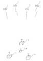
ここでは、GNSSの一例として、GPSを用いた場合を説明するとともに、図1に示すように、3つの基準局からなる基準局網(基準局、基準局網ともkの符号を用いる)の内側エリアに移動局Aが位置している場合について説明する。図1中、符号iは衛星を示す。 Here, a case where GPS is used as an example of GNSS will be described, and as shown in FIG. 1, a mobile station is installed in an inner area of a reference station network composed of three reference stations (both the reference station and the reference station network use the code k). A case where A is located will be described. In FIG. 1, the symbol i indicates a satellite.
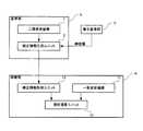
まず、図2に基づき、基準局kと移動局Aとの概略構成について説明する。 First, a schematic configuration of the reference station k and the mobile station A will be described with reference to FIG.
基準局kには、L1周波数(1575.42MHz)およびL2周波数(1227.6MHz)の搬送波を受信し得る二周波受信機1と、この二周波受信機1で得られた各周波数の観測データおよび電子基準局Dから送られる精密暦(放送暦を元にして別途推定された暦、例えばIGS精密暦である)を入力として受信して補正情報を生成する補正情報生成ユニット2とが具備されている。なお、精密暦には、修正(補正)された衛星軌道および衛星時計誤差が含まれている。以下、L1周波数の搬送波をL1波、L2周波数の搬送波をL2波と称す。 The reference station k includes a dual frequency receiver 1 that can receive a carrier wave having an L1 frequency (1575.42 MHz) and an L2 frequency (1227.6 MHz), observation data and electronic data of each frequency obtained by the dual frequency receiver 1. A correction
また、移動局Aには、L1波(一周波)を受信し得る一周波受信機11と、上記基準局網kで生成された補正情報を取得する補正情報取得ユニット12と、上記一周波受信機11で得られた観測データおよび補正情報取得ユニット12からの補正情報を入力として受信して当該移動局Aの位置を高精度で演算する測位演算ユニット13とが具備されている。 The mobile station A includes a
次に、基準局網(ここでは、基準局と称する)kにて得られる補正情報について説明する。 Next, correction information obtained by a reference station network (herein referred to as a reference station) k will be described.
基準局kでは、コードを用いた測位と、L1波およびL2波の二周波の搬送波位相を用いた測位とが行われる。 At the reference station k, positioning using a code and positioning using two-frequency carrier phases of L1 and L2 waves are performed.
ここでは、下記(1)式にて示すコードによる擬似距離の観測式と、下記(2)式にて示す搬送波による位相距離の観測式とが用いられる。 Here, the observation formula of the pseudo distance by the code shown by the following formula (1) and the observation formula of the phase distance by the carrier shown by the following formula (2) are used.
Pifk=ρik+cδk−cδi+(λf2/λ12)Iik+Tk+pfk−pif ・・・(1)
Lifk=ρik+cδk−cδi−(λf2/λ12)Iik+Tk+nifkλf+lfk−lif ・・・(2)
上記各式中の記号は以下の通りである。Pifk = ρik + cδk −cδi + (λf2 / λ12 ) Iik + Tk + pfk −pif (1)
Lifk = ρik + cδk −cδi − (λf2 / λ12 ) Iik + Tk + nifk λf + lfk −lif (2)
Symbols in the above formulas are as follows.
ρik :基準局kと衛星iとの幾何学的距離
c :電波の速度
δk :基準局時計誤差(受信局時計誤差)
δi :衛星時計誤差
Iik :視線方向の電離層遅延量(基準局での)
Tk :天頂方向の対流圏遅延量(基準局での)
λf :搬送波fの波長
nifk :搬送波位相アンビギュイティ
pfk :基準局コードバイアス(ハードウエアによる)
pif :衛星コードバイアス(ハードウエアによる)
lfk :基準局位相バイアス(ハードウエアによる)
lif :衛星位相バイアス(ハードウエアによる)
そして、上記(1)式および(2)式を用いて、衛星時計誤差δi、L1波の衛星コードバイアスpi1、L1波の衛星位相バイアスli1、L1波の視線方向の電離層遅延量(視線方向における遅延量)IikおよびL1波の天頂方向の対流圏遅延量(天頂方向における遅延量)Tkの各パラメータが推定される。すなわち、補正情報が得られる。なお、コードバイアスおよび位相バイアスとは、信号が受信機などの機器の回路(ハードウエア)を通る際の遅延量である。ρik : Geometric distance between reference station k and satellite i c: Radio wave velocity δk : Reference station clock error (receiving station clock error)
δi : Satellite clock error Iik : Ionospheric delay amount in the line of sight (at the reference station)
Tk : Tropospheric delay in the zenith direction (at the reference station)
λf : wavelength of carrier wave f nifk : carrier wave phase ambiguity pfk : reference station code bias (by hardware)
pif: satellite code bias (by hardware)
lfk : Reference station phase bias (by hardware)
lif: satellite phase bias (by hardware)
Then, using the above equations (1) and (2), the satellite clock error δi , the L1 wave satellite code bias pi1 , the L1 wave satellite phase bias li1 , and the L1 wave ionospheric delay in the line-of-sight direction. Each parameter of the amount (delay amount in the line-of-sight direction) Iik and the tropospheric delay amount in the zenith direction (delay amount in the zenith direction) Tk of the L1 wave is estimated. That is, correction information is obtained. The code bias and the phase bias are delay amounts when a signal passes through a circuit (hardware) of a device such as a receiver.
次に、移動局Aでの測位方法を概略的に説明する。 Next, a positioning method in the mobile station A will be schematically described.
移動局Aでは一周波だけを用いて測位が行われる。 In the mobile station A, positioning is performed using only one frequency.
すなわち、L1波に載せられたPコードにより測定された擬似距離(コード擬似距離)と、L1波による位相距離(通常、搬送波位相と呼ばれている)とが用いられる。 That is, the pseudo distance (code pseudo distance) measured by the P code placed on the L1 wave and the phase distance (usually called carrier phase) by the L1 wave are used.
ここでも、基準局の場合について説明したものと同じように、下記(3)式で示すコードによる擬似距離の観測式および下記(4)式で示す一周波の搬送波(L1波)による位相距離の観測式が用いられる。 In this case as well, as described in the case of the reference station, the observation formula of the pseudo distance by the code shown by the following formula (3) and the observation of the phase distance by the single-frequency carrier wave (L1 wave) shown by the following formula (4) An equation is used.
Pi1A=ρiA+cδA−cδi+IiA+TA+p1A−pi1 ・・・(3)
Li1A=ρiA+cδA−cδi−IiA+TA+ni1Aλ1+l1A−li1 ・・・(4)
上記(3)式および(4)式中の記号は以下の通りである。P i 1A = ρ i A + cδ A -cδ i + I i A + T A + p 1A -p i 1 ··· (3)
L i 1A = ρ i A + cδ A -cδ i -I i A + T A + n i 1A λ 1 + l 1A -l i 1 ··· (4)
Symbols in the above formulas (3) and (4) are as follows.
ρiA :移動局Aと衛星iとの幾何学的距離
c :電波の速度
δA :移動局時計誤差(受信局時計誤差)
δi :衛星時計誤差
IiA :視線方向の電離層遅延量
TA :天頂方向の対流圏遅延量
λ1 :L1波の波長
ni1A :L1波の搬送波位相アンビギュイティ
p1A :L1波の移動局コードバイアス(ハードウエアによる)
pi1 :L1波の衛星コードバイアス(ハードウエアによる)
l1A :L1波の移動局位相バイアス(ハードウエアによる)
li1 :L1波の衛星位相バイアス(ハードウエアによる)
なお、衛星時計誤差による距離cδi、L1波の衛星コードバイアスpi1およびL1波の衛星位相バイアスli1は基準局kから送られる値を使用する。また、移動局コードバイアスp1Aはゼロとみなす。ρiA : Geometric distance between mobile station A and satellite i c: Radio wave speed δA : Mobile station clock error (receiving station clock error)
δi : Satellite clock error IiA : Ionospheric delay amount in line of sight TA : Tropospheric delay amount in zenith direction λ1 : Wavelength of L1 wave ni1A : Carrier phase ambiguity of L1 wave p1A : L1 wave Mobile station code bias (depends on hardware)
pi1 : Satellite code bias of L1 wave (by hardware)
l1A : Mobile station phase bias of L1 wave (by hardware)
li1 : L1 wave satellite phase bias (by hardware)
For the distance cδi due to the satellite clock error, the satellite code bias pi1 of the L1 wave, and the satellite phase bias li1 of the L1 wave, values transmitted from the reference station k are used. Further, the mobile station code bias p1A is regarded as zero.
そして、移動局Aでは、コード擬似距離ρiA、時計誤差距離cδA、L1波の移動局位相バイアスl1A、L1波の搬送波位相アンビギュイティni1Aなどの各パラメータがカルマンフィルタにより推定される。In the mobile station A, parameters such as the code pseudorange ρiA , the clock error distance cδA , the mobile station phase bias l1A of the L1 wave, and the carrier phase ambiguity ni1A of the L1 wave are estimated by the Kalman filter. The
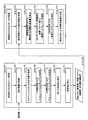
以下、本発明に係る測位方法を、図3のフローチャートに基づき詳しく説明する。
A.基準局側(基準局網)における補正情報の生成手順およびパラメータの推定手順について説明する。Hereinafter, the positioning method according to the present invention will be described in detail based on the flowchart of FIG.
A. A correction information generation procedure and parameter estimation procedure on the reference station side (reference station network) will be described.
まず、基準局網kの観測データにより、各基準局kと衛星iとの間のコード擬似距離並びにL1波およびL2波の搬送波位相(距離)を取得する(ステップ1)。 First, from the observation data of the reference station network k, the code pseudo-range between each reference station k and the satellite i and the carrier phase (distance) of the L1 wave and L2 wave are acquired (step 1).
次に、電子基準局Dから送られる精密暦(予報値)から衛星軌道情報および衛星時計誤差を取得する(ステップ2)。 Next, satellite orbit information and satellite clock error are acquired from the precise calendar (forecast value) sent from the electronic reference station D (step 2).
次に、L1波およびL2波の搬送波位相をゼロ差で(そのままの値で、つまり生値で)保持し、そしてカルマンフィルタを用いて視線方向の電離層遅延量Iik、天頂方向の対流圏遅延量Tkなどの未知数を推定する(ステップ3)。Next, the carrier phase of the L1 wave and the L2 wave is held with zero difference (as it is, that is, as a raw value), and using the Kalman filter, the ionospheric delay amount Iik in the gaze direction, the tropospheric delay amount in the zenith direction An unknown such as Tk is estimated (step 3).
次に、ワイドレーンアンビギュイティを、L1・L2線形結合を用いて決定する(ステップ4)。 Next, the wide lane ambiguity is determined using L1 and L2 linear combination (step 4).
次に、ナローレーンアンビギュイティを、L1・L2線形結合を用いて決定する(ステップ5)。 Next, narrow lane ambiguity is determined using L1 and L2 linear combination (step 5).
なお、これらワイドレーンアンビギュイティおよびナローレーンアンビギュイティの決定に際しては、LAMBDA法(Least-square Ambiguity Decorrelation Adjustment Method)が用いられる。 Note that the LAMBDA method (Least-square Ambiguity Decorrelation Adjustment Method) is used to determine these wide lane ambiguities and narrow lane ambiguities.
これらワイドレーンアンビギュイティおよびナローレーンアンビギュイティから、L1・L2線形結合の搬送波位相アンビギュイティを決定する。 From these wide lane ambiguities and narrow lane ambiguities, the carrier phase ambiguities of the L1 and L2 linear combinations are determined.
次に、上記L1・L2線形結合の搬送波位相アンビギュイティをゼロ差アンビギュイティに戻すとともに上記観測データにカルマンフィルタを適用して、下記に示す残りの未知パラメータを推定する(ステップ6)。 Next, the carrier phase ambiguity of the L1 and L2 linear combination is returned to zero difference ambiguity and a Kalman filter is applied to the observed data to estimate the remaining unknown parameters shown below (step 6).
すなわち、衛星時計誤差の修正値Δδi、L1波の衛星コードバイアスpi1、L1波の衛星位相バイアスli1が推定される。この修正された衛星時計誤差Δδiが精密暦の衛星時計誤差の代わりに用いられる(ステップ7)。That is, the satellite clock error correction value Δδi , the L1 wave satellite code bias pi1 , and the L1 wave satellite phase bias li1 are estimated. This corrected satellite clock error Δδi is used in place of the precise calendar satellite clock error (step 7).
そして、衛星時計誤差の修正値(以下、修正衛星時計誤差と称す)Δδi、およびカルマンフィルタにより得られたL1波の衛星コードバイアスpi1、L1波の衛星位相バイアスli1、視線方向の電離層遅延量Iikおよび天頂方向の対流圏遅延の推定量Δkが補正情報として移動局Aに送られる(ステップ8)。
B.観測点である移動局での計測手順について説明する。Then, a corrected value of the satellite clock error (hereinafter referred to as a corrected satellite clock error) Δδi , a satellite code bias pi1 of the L1 wave obtained by the Kalman filter, a satellite phase bias li1 of the L1 wave, The ionospheric delay amount Iik and the estimated tropospheric delay amount Δk in the zenith direction are sent as correction information to the mobile station A (step 8).
B. The measurement procedure at the mobile station that is the observation point will be described.
まず、移動局Aの観測データによりコード擬似距離、搬送波位相(距離)を取得する(ステップ9)。 First, the code pseudorange and the carrier phase (distance) are acquired from the observation data of the mobile station A (step 9).
次に、上記基準局網kから送られる補正情報、すなわち衛星軌道、修正衛星時計誤差、L1波の衛星コードバイアス、L1波の衛星位相バイアス、天頂方向の対流圏遅延量、視線方向の電離層遅延量などを取得する(ステップ10)。 Next, correction information transmitted from the reference station network k, that is, satellite orbit, corrected satellite clock error, satellite code bias of L1 wave, satellite phase bias of L1 wave, tropospheric delay amount in the zenith direction, ionospheric delay amount in the line of sight, etc. Is acquired (step 10).
次に、視線方向の電離層遅延量および天頂方向の対流圏遅延量を、不正三角網(TIN:Triangle Irregular Network)を用いた内挿法により求める(後述する)(ステップ11)。 Next, the ionospheric delay amount in the line-of-sight direction and the tropospheric delay amount in the zenith direction are obtained by an interpolation method using an irregular triangular network (TIN) (described later) (step 11).
次に、L1波の搬送波位相(距離)およびコード擬似距離をゼロ差で保持するとともに、カルマンフィルタを用いて、L1波の移動局位相バイアス、移動局Aの位置(フロート解としての座標)および一重差アンビギュイティを推定する(ステップ12)。 Next, while maintaining the carrier phase (distance) and code pseudorange of the L1 wave with a zero difference, the Kalman filter is used to set the mobile station phase bias of the L1 wave, the position of the mobile station A (coordinates as a float solution), and the single The difference ambiguity is estimated (step 12).
次に、LAMBDA法を用いて一重差アンビギュイティを整数値として決定する(ステップ13)。 Next, the single difference ambiguity is determined as an integer value using the LAMBDA method (step 13).
上記LAMBDA法にてアンビギュイティを求める前に、ゼロ差アンビギュイティを一重差(衛星間)アンビギュイティに変換する。この一重差アンビギュイティは、2つの衛星を(i,j)とすると、下記(5)式にて表される。 Before obtaining the ambiguity by the LAMBDA method, the zero difference ambiguity is converted into a single difference (inter-satellite) ambiguity. This single difference ambiguity is expressed by the following equation (5), where two satellites are (i, j).
nij1A=ni1A−nj1A ・・・(5)
なお、一重差アンビギュイティは、推定された移動局時計誤差δAおよび移動局位相バイアスl1Aから、独立した(相関が無い)パラメータとして扱われる。nij1A = ni1A -nj1A (5)
Incidentally, single differences ambiguity, from the estimated mobile station clock error [delta]A and the mobile station phase bias l1A, independent (uncorrelated) are treated as a parameter.
そして、上記決定された一重差アンビギュイティおよび他のパラメータを用いて、移動局Aの位置(三次元座標)を決定する(ステップ14)。
C.ここで、視線方向の電離層遅延量および天頂方向の対流圏遅延量の求め方について説明しておく。
(1)視線方向の電離層遅延量の求め方を図4に基づき説明する。Then, using the determined single difference ambiguity and other parameters, the position (three-dimensional coordinates) of the mobile station A is determined (step 14).
C. Here, how to obtain the ionospheric delay amount in the gaze direction and the tropospheric delay amount in the zenith direction will be described.
(1) A method of obtaining the ionospheric delay amount in the line-of-sight direction will be described with reference to FIG.
視線方向の電離層遅延量は、不正三角網(TIN:Triangle Irregular Network)を用いて求められる。 The ionospheric delay amount in the line-of-sight direction is obtained using an irregular triangle network (TIN: Triangle Irregular Network).
まず、移動局Aにおいて、移動局Aが内部に入るように当該移動局Aに近い3つの基準局k(k=1,2,3)を選ぶ。 First, in the mobile station A, three reference stations k (k = 1, 2, 3) close to the mobile station A are selected so that the mobile station A enters inside.
次に、衛星iの位置(軌道)が既知であることから、これら3つの基準局kから衛星iに向けての電離層の貫通点(1′,2′,3′)を求める。なお、この貫通点(1′,2′,3′)とは、衛星iと基準局(正確には受信機)kとを結ぶ直線と電離層最下面(電離層曲面レイヤーともいう)との交点である。そして、各基準局kにおける視線方向の電離層遅延量をI1,I2,I3とすると、移動局Aの視線方向の電離層遅延量IAは、電離層最下面での値と同一とみなすことができるので、電離層最下面での貫通点(1′,2′,3′)に基づき内挿法を用いて電離層遅延量IAを求めることができる。Next, since the position (orbit) of the satellite i is known, the ionosphere penetration points (1 ′, 2 ′, 3 ′) from the three reference stations k toward the satellite i are obtained. The penetrating points (1 ′, 2 ′, 3 ′) are intersections between a straight line connecting the satellite i and the reference station (more precisely, the receiver) k and the lowermost surface of the ionosphere (also referred to as an ionospheric curved surface layer). . When the ionospheric delay amounts in the line-of-sight direction at each reference station k are I1 , I2 , and I3 , the ionospheric delay amount IA in the line-of-sight direction of mobile station A can be regarded as the same as the value at the bottom surface of the ionosphere. since it, through points of ionospheric lowermost surface (1 ', 2', 3 ') can be obtained ionospheric delay Ia using interpolation in based on.
すなわち、移動局Aの視線方向での(視線方向内においての)電離層最下面における貫通点をA′、この貫通点A′から各基準局kの視線方向の貫通点(1′,2′,3′)までの距離をS1,S2,S3とすると、移動局Aの貫通点A′における視線方向の電離層遅延量IA′は下記(6)式にて示すように、距離に反比例する内挿法により求められる。That is, the penetration point on the lowest surface of the ionosphere in the line of sight of the mobile station A (within the line of sight) is A ′, and the point of penetration (1 ′, 2 ′, 3) from the penetration point A ′ to the reference station k in the line of sight. 'the distance to) WhenS 1, S 2, S 3 , through point a of the mobile station a' ionospheric delay of the line of sight direction ofI a ', as shown in the following equation (6), is inversely proportional to the distance Is obtained by interpolation.
IA′=(I1/S1+I2/S2+I3/S3)/(1/S1+1/S2+1/S3) ・・・(6)
(2)天頂方向の対流圏遅延量の求め方について説明する。IA ′ = (I1 / S1 + I2 / S2 + I3 / S3 ) / (1 / S1 + 1 / S2 + 1 / S3 ) (6)
(2) How to determine the amount of tropospheric delay in the zenith direction will be described.
基準局kでの対流圏遅延量Tkは下記(7)式にて与えられる。Tropospheric Delay Tk at the reference station k is given by the following equation (7).
Tk=T0k+Δk ・・・(7)
上記(7)式中、T0kは天頂方向の対流圏遅延量の初期値で、例えば対流圏モデルから、または外部から与えられる。具体的には、T0kは緯度、高度などに基づき求められる。Δkは天頂方向の対流圏遅延量の初期値との差で、例えばカルマンフィルタにより推定される。Tk = T0k + Δk (7)
In the equation (7), T0k is an initial value of the tropospheric delay amount in the zenith direction, and is given from, for example, the troposphere model or from the outside. Specifically, T0k is obtained based on latitude, altitude, and the like. Deltak is estimated by the difference between the initial value of the zenith tropospheric delay, for example, by the Kalman filter.
そして、移動局Aにおける天頂方向の対流圏遅延量TAは下記(8)式にて与えられる。The troposphere delay TA zenith direction in the mobile station A is given by the following equation (8).
TA=T0A+ΔA ・・・(8)
上記(8)式中、T0Aは対流圏モデルから得られ、ΔAは、電離層遅延量の場合と同様に、不正三角網(TIN)を用いて求められる。TA = T0A + ΔA (8)
In the above equation (8), T0A is obtained from the troposphere model, and ΔA is obtained using an incorrect triangular network (TIN), as in the case of the ionospheric delay amount.
すなわち、ΔAは各基準局k(=1,2,3)における天頂方向の対流圏遅延量Tk(T1,T2,T3)から、下記(9)式に示すように、距離Sに反比例する内挿法により求められる。That, deltaA from zenith tropospheric delayT k (T 1, T 2 , T 3) in each reference station k (= 1, 2, 3), as shown in the following equation (9), the distance S Obtained by inversely proportional interpolation.
ΔA=(Δ1/S1+Δ2/S2+Δ3/S3)/(1/S1+1/S2+1/S3) ・・・(9)
ここで、上述した測位方法を実行する測位装置の構成について説明しておく。ΔA = (Δ1 / S1 + Δ2 / S2 + Δ3 / S3 ) / (1 / S1 + 1 / S2 + 1 / S3 ) (9)
Here, the configuration of a positioning device that executes the positioning method described above will be described.
すなわち、図5に示すように、この測位装置10(移動局Aでもある)は、全地球衛星測位システムからの測位電波を移動局Aにて受信するとともに基準局網(基準局側)kからの補正情報を用いて当該移動局Aにて一周波による測位を行う装置であり、
測位装置10は、
衛星iからの測位電波を受信してコードによる擬似距離および搬送波による位相距離を観測する一周波受信機である距離観測ユニット11と、
上記基準局網kから送られる修正衛星軌道、修正衛星時計誤差、並びに基準局網kでの電離層遅延量および対流圏遅延量などの補正情報を取得する補正情報取得ユニット12と、
上記補正情報取得ユニット12からの補正情報を入力として受信して移動局Aでの電離層遅延量および対流圏遅延量を算出する遅延量算出ユニット21と、
上記コードによる擬似距離、搬送波による位相距離、電離層遅延量および対流圏遅延量を入力として受信してカルマンフィルタにより、移動局Aでの一周波の位相バイアス、移動局Aの位置および一重差アンビギュイティを推定する位置等推定ユニット22と、
上記位置等推定ユニット22にて推定された一重差アンビギュイティを入力として受信して一重差アンビギュイティを決定するアンビギュイティ決定ユニット23と、
上記アンビギュイティ決定ユニット23にて決定された一重差アンビギュイティを入力として受信して移動局Aの位置を決定する位置決定ユニット24とを具備し、
且つ上記測位を行う際に、前記測位装置10は、コードによる擬似距離観測式および搬送波による位相距離観測式を用いるとともに、
上記擬似距離観測式を、測位電波を受信する基準局または移動局である受信局と衛星との間の幾何学的距離に、衛星時計誤差、受信局時計誤差、電離層遅延量および対流圏遅延量を考慮し且つ上記受信局および衛星における一周波のコードバイアスを考慮したものとなし、
上記位相距離観測式を、測位電波を受信する受信局と衛星との間の幾何学的距離に、衛星時計誤差、受信局時計誤差、電離層遅延量、対流圏遅延量および搬送波位相アンビギュイティを考慮し且つ上記受信局および衛星における一周波の位相バイアスを考慮したものを用いたものである。That is, as shown in FIG. 5, the positioning device 10 (also mobile station A) receives the positioning radio wave from the global satellite positioning system at the mobile station A and corrects it from the reference station network (reference station side) k. It is a device that performs positioning by one frequency in the mobile station A using information,
The
A
A correction
A delay
The pseudorange by the above code, the phase distance by the carrier wave, the ionospheric delay amount and the tropospheric delay amount are received as input, and the Kalman filter is used to calculate the phase bias of one frequency at the mobile station A, the position of the mobile station A and the single difference ambiguity. A
An
A
And when performing the above positioning, the
Using the above pseudorange observation formula, the satellite clock error, receiver clock error, ionospheric delay, and tropospheric delay are taken into account for the geometric distance between the receiving station, which is the reference or mobile station that receives positioning radio waves, and the satellite. And taking into account the single-frequency code bias in the receiving station and satellite,
In the above phase distance observation formula, satellite clock error, receiver station clock error, ionospheric delay amount, tropospheric delay amount, and carrier phase ambiguity are considered in the geometric distance between the receiving station and satellite that receive positioning radio waves. In addition, the one that takes into account the phase bias of one frequency in the receiving station and the satellite is used.
なお、上述した測位演算ユニット13に、遅延量算出ユニット21、位置等推定ユニット22、アンビギュイティ決定ユニット23および位置決定ユニット24が設けられている。 Note that the
上述したように、基準局網にて一周波の衛星コードバイアスおよび衛星位相バイアスを得るとともに、これらのバイアスを移動局に補正情報として送るようにしたので、一周波の受信機にてアンビギュイティを決定することができる。 As described above, since the satellite code bias and satellite phase bias of one frequency are obtained in the reference station network, and these biases are sent to the mobile station as correction information, the ambiguity is set by the receiver of one frequency. Can be determined.
すなわち、観測式としてコードによる擬似距離観測式および搬送波による位相距離観測式を用いるとともに、これらの観測式を、コードバイアスおよび位相バイアスを考慮したものとし、且つ基準局網にて、衛星側のコードバイアスおよび位相バイアスを推定してこれらのバイアスを移動局に送るようにしたので、移動局にて、一周波による観測式における少なくとも位相バイアスを推定することができ、したがって一周波受信機を用いた場合でも、搬送波位相アンビギュイティを決定することができる。言い換えれば、安価な一周波受信機であっても、高精度な測位を行うことができる。 In other words, the pseudo-range observation formula by the code and the phase distance observation formula by the carrier wave are used as the observation formula, and these observation formulas consider the code bias and the phase bias, and the code bias on the satellite side in the reference station network And the phase biases are estimated and sent to the mobile station, so that the mobile station can estimate at least the phase bias in the single-frequency observation formula, and therefore uses a single-frequency receiver. However, the carrier phase ambiguity can be determined. In other words, even an inexpensive single-frequency receiver can perform highly accurate positioning.
A 移動局
i 衛星
k 基準局網,基準局
1 二周波受信機
2 補正情報生成ユニット
11 一周波受信機,距離観測ユニット
12 補正情報取得ユニット
13 測位演算ユニット
21 遅延量算出ユニット
22 位置等推定ユニット
23 アンビギュイティ決定ユニット
24 位置決定ユニット
A mobile station i satellite k reference station network, reference station 1
Claims (2)
Translated fromJapaneseコードによる擬似距離観測式および搬送波による位相距離観測式を用い、
上記擬似距離観測式を、衛星時計誤差、受信局時計誤差、電離層遅延量および対流圏遅延量を用いて、測位電波を受信する基準局または移動局である受信局と衛星との間の距離と、上記受信局および衛星におけるコードバイアスで表したものとし、
上記位相距離観測式を、衛星時計誤差、受信局時計誤差、電離層遅延量、対流圏遅延量および搬送波位相アンビギュイティを用いて、測位電波を受信する受信局と衛星との間の距離と、上記受信局および衛星における位相バイアスで表したものとし、
上記基準局側にて、衛星時計誤差、一周波の衛星コードバイアスおよび衛星位相バイアス、電離層遅延量並びに対流圏遅延量の各パラメータを推定し、
上記移動局にて、上記推定された各パラメータ並びに移動局での電離層遅延量および対流圏遅延量を用いて、コードによる擬似距離、時計誤差に基づく距離、少なくとも一周波の移動局位相バイアス、および搬送波位相アンビギュイティを推定した後、上記搬送波位相アンビギュイティを決定して衛星と移動局との間の距離を求め、ここで上記移動局での各遅延量は、基準局側から移動局までの距離と、当該基準局側での遅延量とに基づいて内挿法により求めることを特徴とする衛星測位システムを用いた測位方法。A method of receiving a positioning radio wave from a satellite positioning system and correction information from a reference station side and positioning a mobile station using one frequency of the positioning radio wave,
Using the pseudorange observation formula by code and the phase distance observation formula by carrier wave,
Using the above pseudorange observation formula, satellite clock error, receiving station clock error, ionospheric delay amount and tropospheric delay amount, the distance between the receiving station and the satellite that is a reference station or mobile station that receives positioning radio waves, and the above It is expressed as a code bias at the receiving station and satellite.
Using the phase distance observation formula, satellite clock error, receiving station clock error, ionospheric delay amount, tropospheric delay amount and carrier phase ambiguity, the distance between the receiving station that receives the positioning radio wave and the satellite, and the above It is expressed in phase bias at the receiving station and satellite.
Estimate each parameter of satellite clock error, single frequency satellite code bias and satellite phase bias, ionospheric delay amount and tropospheric delay amount on the reference station side,
In the mobile station, using the estimated parameters and the ionospheric delay amount and tropospheric delay amount in the mobile station, a pseudo-range by code, a distance based on a clock error, a mobile station phase bias of at least one frequency, and a carrier wave After estimating the phase ambiguity, the carrier phase ambiguity is determined to determine the distance between the satellite and the mobile station. Here, each delay amount at the mobile station is determined from the reference station side to the mobile station. A positioning method using a satellite positioning system, which is obtained by interpolation based on a distance and a delay amount on the reference station side.
衛星からの測位電波を受信してコードによる擬似距離および搬送波による位相距離を観測するように構成された距離観測ユニットと、
基準局側から送られる衛星軌道、衛星時計誤差、並びに基準局側での電離層遅延量および対流圏遅延量などの補正情報を取得するように構成された補正情報取得ユニットと、
上記補正情報取得ユニットからの補正情報を入力として受信して移動局での電離層遅延量および対流圏遅延量を算出するように構成された遅延量算出ユニットと、
上記擬似距離、位相距離、電離層遅延量および対流圏遅延量を入力として受信して移動局の位置および一重差アンビギュイティを推定するように構成された位置等推定ユニットと、
上記位置等推定ユニットにて推定された一重差アンビギュイティを入力として受信して一重差アンビギュイティを決定するように構成されたアンビギュイティ決定ユニットと、
上記アンビギュイティ決定ユニットにて決定された一重差アンビギュイティを入力として受信して移動局の位置を決定するように構成された位置決定ユニットとを具備し、
且つ上記測位を行う際に、コードによる擬似距離観測式および搬送波による位相距離観測式を用いるとともに、
上記擬似距離観測式を、衛星時計誤差、受信局時計誤差、電離層遅延量および対流圏遅延量を用いて、測位電波を受信する基準局または移動局である受信局と衛星との間の距離と、上記受信局および衛星における一周波のコードバイアスで表したものとし、
上記位相距離観測式を、衛星時計誤差、受信局時計誤差、電離層遅延量、対流圏遅延量および搬送波位相アンビギュイティを用いて、測位電波を受信する受信局と衛星との間の距離と、上記受信局および衛星における一周波の位相バイアスで表したものとすることを特徴とする衛星測位システムを用いた測位装置。An apparatus for executing a positioning method using the satellite positioning system according to claim 1 in a mobile station,
A distance observation unit configured to receive a positioning radio wave from a satellite and observe a pseudo distance by a code and a phase distance by a carrier;
A correction information acquisition unit configured to acquire correction information such as satellite orbit, satellite clock error sent from the reference station side, and ionospheric delay amount and tropospheric delay amount on the reference station side;
A delay amount calculation unit configured to receive the correction information from the correction information acquisition unit as an input and calculate an ionospheric delay amount and a tropospheric delay amount in the mobile station;
A position estimation unit configured to receive the pseudorange, phase distance, ionospheric delay amount and tropospheric delay amount as input to estimate the position and single difference ambiguity of the mobile station;
An ambiguity determining unit configured to receive a single difference ambiguity estimated by the position estimation unit as an input and determine a single difference ambiguity;
A position determining unit configured to receive a single difference ambiguity determined by the ambiguity determining unit as an input and determine a position of the mobile station; and
And when performing the above positioning, while using the pseudo distance observation formula by the code and the phase distance observation formula by the carrier wave,
Using the above pseudorange observation formula, satellite clock error, receiving station clock error, ionospheric delay amount and tropospheric delay amount, the distance between the receiving station and the satellite that is a reference station or mobile station that receives positioning radio waves, and the above Expressed as a single-frequency code bias at the receiving station and satellite,
Using the phase distance observation formula, satellite clock error, receiving station clock error, ionospheric delay amount, tropospheric delay amount and carrier phase ambiguity, the distance between the receiving station that receives the positioning radio wave and the satellite, and the above A positioning device using a satellite positioning system, characterized in that it is expressed by a phase bias of one frequency at a receiving station and a satellite.
Applications Claiming Priority (2)
| Application Number | Priority Date | Filing Date | Title |
|---|---|---|---|
| US15/079,908 | 2016-03-24 | ||
| US15/079,908US10012738B2 (en) | 2016-03-24 | 2016-03-24 | Positioning method and positioning apparatus using satellite positioning system |
Publications (2)
| Publication Number | Publication Date |
|---|---|
| JP2017173327Atrue JP2017173327A (en) | 2017-09-28 |
| JP7153427B2 JP7153427B2 (en) | 2022-10-14 |
Family
ID=59898543
Family Applications (1)
| Application Number | Title | Priority Date | Filing Date |
|---|---|---|---|
| JP2017056762AActiveJP7153427B2 (en) | 2016-03-24 | 2017-03-23 | POSITIONING METHOD AND POSITIONING DEVICE USING SATELLITE POSITIONING SYSTEM |
Country Status (2)
| Country | Link |
|---|---|
| US (1) | US10012738B2 (en) |
| JP (1) | JP7153427B2 (en) |
Cited By (4)
| Publication number | Priority date | Publication date | Assignee | Title |
|---|---|---|---|---|
| JP2020186960A (en)* | 2019-05-13 | 2020-11-19 | アルパイン株式会社 | Positioning method and positioning system |
| CN112034489A (en)* | 2020-07-20 | 2020-12-04 | 中国科学院空天信息创新研究院 | Global ionized layer grid generation method based on multi-source data fusion |
| CN114236587A (en)* | 2021-11-26 | 2022-03-25 | 国网思极神往位置服务(北京)有限公司 | Network RTK solution method and storage medium based on Beidou ground enhancement |
| CN117075164A (en)* | 2023-08-18 | 2023-11-17 | 同济大学 | GNSS satellite clock error parameterization resolving application method and system |
Families Citing this family (18)
| Publication number | Priority date | Publication date | Assignee | Title |
|---|---|---|---|---|
| FR3049354B1 (en)* | 2016-03-25 | 2018-03-16 | Thales | SATELLITE GEOPOSITIONING METHOD AND ASSOCIATED TERMINAL |
| CN108196284B (en)* | 2018-01-20 | 2021-07-27 | 中国人民解放军61540部队 | GNSS network data processing method for fixing single-difference ambiguity between satellites |
| NO20180681A1 (en)* | 2018-05-14 | 2019-11-15 | Indra Navia As | Multi Frequency Monitor for detecting ionospheric and tropospheric disturbances |
| WO2019220413A1 (en)* | 2018-05-18 | 2019-11-21 | Telefonaktiebolaget Lm Ericsson (Publ) | Methods for handling gnss reference system information of reference stations |
| CN109932731B (en)* | 2019-03-12 | 2023-05-09 | 辽宁工程技术大学 | BDS satellite reference station ionosphere error determination method |
| CN111896977B (en)* | 2019-05-06 | 2024-03-29 | 千寻位置网络有限公司 | Troposphere wet delay precision calculation method and system and positioning method and system thereof |
| CN110412633B (en)* | 2019-07-30 | 2021-06-08 | 广州市中海达测绘仪器有限公司 | Positioning method, positioning device, computer equipment and storage medium |
| CN112799105B (en)* | 2020-12-30 | 2022-04-22 | 中国电子科技集团公司第五十四研究所 | Time synchronization and evaluation method between formation LEO satellite satellites |
| CN113325448A (en)* | 2021-04-21 | 2021-08-31 | 中铁第一勘察设计院集团有限公司 | Large-altitude-difference CORS network resolving method considering troposphere delay reconstruction |
| CN113341437B (en)* | 2021-05-21 | 2024-05-28 | 东南大学 | GNSS unmodeled error inversion method |
| CN114355419B (en)* | 2021-12-15 | 2023-04-25 | 中国科学院国家授时中心 | RTK product positioning method and device for distributed Beidou position service center |
| CN114966760B (en)* | 2022-06-15 | 2023-08-22 | 中国科学院精密测量科学与技术创新研究院 | Ionosphere weighted non-differential non-combination PPP-RTK technology implementation method |
| CN115113234A (en)* | 2022-06-23 | 2022-09-27 | 涟漪位置(广州)科技有限公司 | Method for generating improved ionospheric grid product, terminal and readable storage medium |
| CN115963522B (en)* | 2022-11-29 | 2024-01-26 | 国网思极位置服务有限公司 | A positioning method and terminal combining base station satellite data |
| CN116243591B (en)* | 2023-01-28 | 2023-09-29 | 北京航空航天大学 | Subnanosecond time service method integrating UTC (k) and Beidou broadcast ephemeris |
| CN117741714B (en)* | 2023-12-19 | 2024-08-23 | 中国科学院上海天文台 | GPS satellite pseudo-range deviation correction method for improving satellite-based enhanced service precision |
| CN117891154B (en)* | 2023-12-28 | 2025-08-01 | 上海卫星工程研究所 | Method and system for controlling time-frequency consistency of formation satellite based on atomic clock |
| CN117761740B (en)* | 2024-02-22 | 2024-05-14 | 开普勒卫星科技(武汉)有限公司 | Precision desensitization algorithm for multi-system reference station receiver |
Citations (11)
| Publication number | Priority date | Publication date | Assignee | Title |
|---|---|---|---|---|
| US20040130485A1 (en)* | 2002-09-23 | 2004-07-08 | Rapoport Lev Borisovich | Position estimation using a network of a global-positioning receivers |
| WO2006121023A1 (en)* | 2005-05-09 | 2006-11-16 | Sueo Sugimoto | Global positioning device, and global positioning system |
| US20100141510A1 (en)* | 2008-12-09 | 2010-06-10 | Dai Liwen L | Methods and systems to increase accuracy in the navigation of single frequency receivers |
| US20110122020A1 (en)* | 2008-04-22 | 2011-05-26 | Patrick Henkel | Method for a global satellite navigation system |
| JP2012042371A (en)* | 2010-08-20 | 2012-03-01 | Electronic Navigation Research Institute | Method and apparatus of detecting ionosphere abnormality in satellite navigation system |
| JP2012520449A (en)* | 2009-03-13 | 2012-09-06 | セントル・ナショナル・デチュード・スパシアル | Satellite positioning method using auxiliary data |
| JP2012211795A (en)* | 2011-03-31 | 2012-11-01 | Hitachi Zosen Corp | Method and device for measuring medium-frequency wave on sea surface |
| JP2013510298A (en)* | 2009-11-03 | 2013-03-21 | ノヴァテル インコーポレイテッド | Centimeter-accurate positioning method using low-cost single-frequency GNSS receiver |
| JP2015007640A (en)* | 2009-11-17 | 2015-01-15 | トプコン ポジショニング システムズ, インク. | Determination of ambiguity in gloval navigation satellite system including first navigation receiver located in rover and second navigation located in base station |
| JP2015092185A (en)* | 2007-03-29 | 2015-05-14 | セントル・ナショナル・デチュード・スパシアル | Method of processing radio-navigation signals |
| US20150293233A1 (en)* | 2012-10-25 | 2015-10-15 | Fugron N.V. | Ppp-rtk method and system for gnss signal based position determination |
Family Cites Families (2)
| Publication number | Priority date | Publication date | Assignee | Title |
|---|---|---|---|---|
| FR2943868A1 (en)* | 2009-03-27 | 2010-10-01 | Thales Sa | METHODS OF CALCULATING THE POSITION OF A GNSS RECEIVER FROM PSEUDO-MEASUREMENTS BI AND MONO FREQUENCIES |
| FR3025610B1 (en)* | 2014-09-05 | 2022-01-14 | Centre Nat Etd Spatiales | METHOD FOR COLLABORATIVE DETERMINATION OF POSITIONING ERRORS OF A SATELLITE NAVIGATION SYSTEM |
- 2016
- 2016-03-24USUS15/079,908patent/US10012738B2/enactiveActive
- 2017
- 2017-03-23JPJP2017056762Apatent/JP7153427B2/enactiveActive
Patent Citations (11)
| Publication number | Priority date | Publication date | Assignee | Title |
|---|---|---|---|---|
| US20040130485A1 (en)* | 2002-09-23 | 2004-07-08 | Rapoport Lev Borisovich | Position estimation using a network of a global-positioning receivers |
| WO2006121023A1 (en)* | 2005-05-09 | 2006-11-16 | Sueo Sugimoto | Global positioning device, and global positioning system |
| JP2015092185A (en)* | 2007-03-29 | 2015-05-14 | セントル・ナショナル・デチュード・スパシアル | Method of processing radio-navigation signals |
| US20110122020A1 (en)* | 2008-04-22 | 2011-05-26 | Patrick Henkel | Method for a global satellite navigation system |
| US20100141510A1 (en)* | 2008-12-09 | 2010-06-10 | Dai Liwen L | Methods and systems to increase accuracy in the navigation of single frequency receivers |
| JP2012520449A (en)* | 2009-03-13 | 2012-09-06 | セントル・ナショナル・デチュード・スパシアル | Satellite positioning method using auxiliary data |
| JP2013510298A (en)* | 2009-11-03 | 2013-03-21 | ノヴァテル インコーポレイテッド | Centimeter-accurate positioning method using low-cost single-frequency GNSS receiver |
| JP2015007640A (en)* | 2009-11-17 | 2015-01-15 | トプコン ポジショニング システムズ, インク. | Determination of ambiguity in gloval navigation satellite system including first navigation receiver located in rover and second navigation located in base station |
| JP2012042371A (en)* | 2010-08-20 | 2012-03-01 | Electronic Navigation Research Institute | Method and apparatus of detecting ionosphere abnormality in satellite navigation system |
| JP2012211795A (en)* | 2011-03-31 | 2012-11-01 | Hitachi Zosen Corp | Method and device for measuring medium-frequency wave on sea surface |
| US20150293233A1 (en)* | 2012-10-25 | 2015-10-15 | Fugron N.V. | Ppp-rtk method and system for gnss signal based position determination |
Non-Patent Citations (1)
| Title |
|---|
| 高須 知二 外2名: "移動体向け広域型ネットワークRTKシステムの検討 Study of Wide-Area Network-RTK System for Mobile U", 電子情報通信学会技術研究報告 IEICE TECHNICAL REPORT, vol. 第108巻,第169号, JPN6021048698, 8 July 2008 (2008-07-08), JP, pages 13 - 18, XP008185637, ISSN: 0004655678* |
Cited By (6)
| Publication number | Priority date | Publication date | Assignee | Title |
|---|---|---|---|---|
| JP2020186960A (en)* | 2019-05-13 | 2020-11-19 | アルパイン株式会社 | Positioning method and positioning system |
| JP7337444B2 (en) | 2019-05-13 | 2023-09-04 | アルパイン株式会社 | Positioning method and positioning system |
| CN112034489A (en)* | 2020-07-20 | 2020-12-04 | 中国科学院空天信息创新研究院 | Global ionized layer grid generation method based on multi-source data fusion |
| CN112034489B (en)* | 2020-07-20 | 2023-04-14 | 中国科学院空天信息创新研究院 | A Global Ionospheric Grid Generation Method Based on Multi-source Data Fusion |
| CN114236587A (en)* | 2021-11-26 | 2022-03-25 | 国网思极神往位置服务(北京)有限公司 | Network RTK solution method and storage medium based on Beidou ground enhancement |
| CN117075164A (en)* | 2023-08-18 | 2023-11-17 | 同济大学 | GNSS satellite clock error parameterization resolving application method and system |
Also Published As
| Publication number | Publication date |
|---|---|
| US20170276800A1 (en) | 2017-09-28 |
| JP7153427B2 (en) | 2022-10-14 |
| US10012738B2 (en) | 2018-07-03 |
Similar Documents
| Publication | Publication Date | Title |
|---|---|---|
| JP7153427B2 (en) | POSITIONING METHOD AND POSITIONING DEVICE USING SATELLITE POSITIONING SYSTEM | |
| US7576690B2 (en) | Position determination with reference data outage | |
| US10185038B2 (en) | Integer ambiguity-fixed precise point positioning method and system | |
| US10048386B2 (en) | Precise GNSS positioning system with improved ambiguity estimation | |
| US7911378B2 (en) | System and method for applying code corrections for GNSS positioning | |
| US10739471B2 (en) | GNSS receiver with a capability to resolve ambiguities using an uncombined formulation | |
| JP6023225B2 (en) | Method for processing wireless navigation signals | |
| EP2575271A1 (en) | Position Estimation Using a Network of Global-Positioning Receivers | |
| US9389317B2 (en) | Method and apparatus for determining position in a global navigation satellite system | |
| KR102188880B1 (en) | Terminal, base station and location positioning method | |
| CN117836669A (en) | DGNSS using reference station carrier phase measurements | |
| EP3657218A1 (en) | Method and system for recreating unavailable gnss measurements | |
| TW202208880A (en) | Rtk gnss positioning without base stations | |
| US20230129514A1 (en) | Positioning system and method | |
| CN110568464A (en) | BDS/GNSS (broadband navigation satellite system/global navigation satellite system) multi-mode chip-based precision positioning method and device | |
| CN119698562A (en) | Crossover frequency correction for precise positioning | |
| CN119343610A (en) | Real-time PPE base station measurement uncertainty modeling for protection level calculation | |
| JP2015068767A (en) | Positioning system, device, method, and program | |
| GB2528117A (en) | Method and apparatus for instantaneous positioning and timing without initial information | |
| US20230194731A1 (en) | Calculating a position of one device relative to another | |
| US11294072B2 (en) | Method, device and server for estimation of IFB calibration value | |
| JP4928114B2 (en) | Carrier phase relative positioning device | |
| JP2012211795A (en) | Method and device for measuring medium-frequency wave on sea surface | |
| KR20110127274A (en) | Positioning method using auxiliary data | |
| JP7754469B1 (en) | Method and program for measuring ionospheric propagation delay at satellite navigation receiving station |
Legal Events
| Date | Code | Title | Description |
|---|---|---|---|
| A621 | Written request for application examination | Free format text:JAPANESE INTERMEDIATE CODE: A621 Effective date:20200117 | |
| A977 | Report on retrieval | Free format text:JAPANESE INTERMEDIATE CODE: A971007 Effective date:20201217 | |
| A131 | Notification of reasons for refusal | Free format text:JAPANESE INTERMEDIATE CODE: A131 Effective date:20210105 | |
| A601 | Written request for extension of time | Free format text:JAPANESE INTERMEDIATE CODE: A601 Effective date:20210330 | |
| A521 | Request for written amendment filed | Free format text:JAPANESE INTERMEDIATE CODE: A523 Effective date:20210510 | |
| A131 | Notification of reasons for refusal | Free format text:JAPANESE INTERMEDIATE CODE: A131 Effective date:20211207 | |
| A601 | Written request for extension of time | Free format text:JAPANESE INTERMEDIATE CODE: A601 Effective date:20220224 | |
| A521 | Request for written amendment filed | Free format text:JAPANESE INTERMEDIATE CODE: A523 Effective date:20220408 | |
| TRDD | Decision of grant or rejection written | ||
| A01 | Written decision to grant a patent or to grant a registration (utility model) | Free format text:JAPANESE INTERMEDIATE CODE: A01 Effective date:20220906 | |
| A61 | First payment of annual fees (during grant procedure) | Free format text:JAPANESE INTERMEDIATE CODE: A61 Effective date:20221003 | |
| R150 | Certificate of patent or registration of utility model | Ref document number:7153427 Country of ref document:JP Free format text:JAPANESE INTERMEDIATE CODE: R150 | |
| R250 | Receipt of annual fees | Free format text:JAPANESE INTERMEDIATE CODE: R250 |