Movatterモバイル変換


[0]ホーム

URL:


JP2017170343A - Sterilization vessel - Google Patents

Sterilization vessel
Download PDF

Info

Publication number
JP2017170343A
JP2017170343AJP2016059246AJP2016059246AJP2017170343AJP 2017170343 AJP2017170343 AJP 2017170343AJP 2016059246 AJP2016059246 AJP 2016059246AJP 2016059246 AJP2016059246 AJP 2016059246AJP 2017170343 AJP2017170343 AJP 2017170343A
Authority
JP
Japan
Prior art keywords
container
lid
liquid
battery
water
Prior art date
Legal status (The legal status is an assumption and is not a legal conclusion. Google has not performed a legal analysis and makes no representation as to the accuracy of the status listed.)
Pending
Application number
JP2016059246A
Other languages
Japanese (ja)
Inventor
友也 岩橋
Tomoya Iwahashi
友也 岩橋
和繁 杉田
Kazushige Sugita
和繁 杉田
Current Assignee (The listed assignees may be inaccurate. Google has not performed a legal analysis and makes no representation or warranty as to the accuracy of the list.)
Panasonic Intellectual Property Management Co Ltd
Original Assignee
Panasonic Intellectual Property Management Co Ltd
Priority date (The priority date is an assumption and is not a legal conclusion. Google has not performed a legal analysis and makes no representation as to the accuracy of the date listed.)
Filing date
Publication date
Application filed by Panasonic Intellectual Property Management Co LtdfiledCriticalPanasonic Intellectual Property Management Co Ltd
Priority to JP2016059246ApriorityCriticalpatent/JP2017170343A/en
Publication of JP2017170343ApublicationCriticalpatent/JP2017170343A/en
Pendinglegal-statusCriticalCurrent

Links

Images

Landscapes

Abstract

Translated fromJapanese

【課題】電力供給が不安定な場所でも使用可能な殺菌容器を提供する。
【解決手段】殺菌容器は、内部に注液するための開口部11であって、飲用口を兼ねる開口部11を有し、かつ、液体が貯められる容器部10と、開口部11を塞ぐための、容器部10に着脱可能な蓋部20と、容器部10の内部に配置され、容器部10に貯められる液体に紫外線を照射することで、液体を殺菌する紫外線光源部30と、容器部10又は蓋部20に設けられた圧電素子60と、圧電素子60が発電した電力を用いて紫外線光源部30を点灯させる駆動回路部40とを備える。
【選択図】図2
Disclosed is a sterilization container that can be used even in places where power supply is unstable.
A sterilization container has an opening 11 for injecting liquid therein, and has an opening 11 serving also as a drinking mouth, and for closing the opening 10 and a container 10 for storing liquid. The lid part 20 that can be attached to and detached from the container part 10, the ultraviolet light source part 30 that is disposed inside the container part 10 and sterilizes the liquid by irradiating the liquid stored in the container part 10 with ultraviolet light, and the container part 10 or the piezoelectric element 60 provided in the cover part 20 and the drive circuit part 40 which lights the ultraviolet light source part 30 using the electric power which the piezoelectric element 60 generated.
[Selection] Figure 2

Description

Translated fromJapanese

本発明は、液体の殺菌機能を有する殺菌容器に関する。  The present invention relates to a sterilization container having a liquid sterilization function.

従来、家庭に配水されている水道水などを、紫外線によって殺菌してから飲用水として用いるということが行われている。これは、たとえ水道水であっても、マイクロコッカス菌又は大腸菌などの細菌が混入している場合があるためである。特に、発展途上国などにおいては、家庭用の水道水であっても充分に殺菌処理が行われていない場合、あるいは、配水途中で細菌が混入する場合がある。  Conventionally, tap water or the like distributed in homes is sterilized with ultraviolet rays and then used as drinking water. This is because even tap water may be contaminated with bacteria such as micrococcus or E. coli. In particular, in developing countries and the like, even household tap water may not be sufficiently sterilized, or bacteria may be mixed during water distribution.

家庭でも使用できる水殺菌装置としては、水道からの原水を濾過フィルタに通した後、流れる濾過水に紫外線を照射して殺菌し、殺菌後の水をタンクなどに貯水する技術が知られている(例えば、特許文献1参照)。タンクには、給水口(蛇口)が取り付けられており、当該給水口から給水して飲用水又は料理用の水として利用することができる。  As a water sterilizer that can be used at home, a technique is known in which raw water from a water supply is passed through a filter and then sterilized by irradiating the filtered water with ultraviolet rays and the sterilized water is stored in a tank or the like. (For example, refer to Patent Document 1). A water supply port (faucet) is attached to the tank, and water can be supplied from the water supply port and used as drinking water or cooking water.

特開2005−211851号公報JP 2005-211851 A

上記従来の水殺菌装置では、紫外線を照射するためには、電力供給を受ける必要がある。このため、電力供給が安定しない地域では、紫外線を照射することができず、水を殺菌することができない。  In the conventional water sterilizer, it is necessary to receive power supply in order to irradiate ultraviolet rays. For this reason, in an area where power supply is not stable, ultraviolet rays cannot be irradiated and water cannot be sterilized.

そこで、本発明は、電力供給の不安定な場所でも使用可能な殺菌容器を提供することを目的とする。  Then, an object of this invention is to provide the sterilization container which can be used also in the place where electric power supply is unstable.

上記目的を達成するため、本発明の一態様に係る殺菌容器は、内部に注液するための開口部であって、飲用口を兼ねる開口部を有し、かつ、液体が貯められる容器部と、前記開口部を塞ぐための、前記容器部に着脱可能な蓋部と、前記容器部の内部に配置され、前記容器部に貯められる液体に紫外線を照射することで、前記液体を殺菌する紫外線光源部と、前記容器部又は前記蓋部に設けられた圧電素子と、前記圧電素子が発電した電力を用いて前記紫外線光源部を点灯させる駆動回路部とを備える。  In order to achieve the above object, a sterilization container according to one aspect of the present invention is an opening for injecting liquid therein, an opening serving also as a drinking mouth, and a container for storing liquid A lid portion that can be attached to and detached from the container portion for closing the opening portion, and an ultraviolet ray that is disposed inside the container portion and that sterilizes the liquid by irradiating the liquid stored in the container portion with ultraviolet rays. A light source section; a piezoelectric element provided in the container section or the lid section; and a drive circuit section that turns on the ultraviolet light source section using electric power generated by the piezoelectric element.

本発明に係る殺菌容器によれば、電力供給の不安定な場所でも使用することができる。  The sterilization container according to the present invention can be used even in places where power supply is unstable.

実施の形態に係る蓋付きマグの斜視図である。It is a perspective view of the mug with a lid concerning an embodiment.実施の形態に係る蓋付きマグの蓋部を取り外した状態を示す斜視図である。It is a perspective view which shows the state which removed the cover part of the mug with a cover which concerns on embodiment.実施の形態に係る蓋付きマグの分解斜視図である。It is a disassembled perspective view of the mug with a lid concerning an embodiment.図1のIV−IV線における実施の形態に係る蓋付きマグの部分断面斜視図である。FIG. 4 is a partial cross-sectional perspective view of a lidded mug according to the embodiment taken along line IV-IV in FIG. 1.実施の形態に係る蓋付きマグの動作及び使用方法を説明するための模式図である。It is a schematic diagram for demonstrating the operation | movement and usage method of the mug with a cover which concerns on embodiment.実施の形態に係る蓋付きマグを振ったときの内部の様子を模式的に示す断面図である。It is sectional drawing which shows typically the mode of an inside when the mug with a lid concerning embodiment is shaken.

以下では、本発明の実施の形態に係る殺菌容器について、図面を用いて詳細に説明する。なお、以下に説明する実施の形態は、いずれも本発明の好ましい一具体例を示すものである。したがって、以下の実施の形態で示される数値、形状、材料、構成要素、構成要素の配置及び接続形態、ステップ、ステップの順序などは、一例であり、本発明を限定する趣旨ではない。よって、以下の実施の形態における構成要素のうち、本発明の最上位概念を示す独立請求項に記載されていない構成要素については、任意の構成要素として説明される。  Below, the sterilization container which concerns on embodiment of this invention is demonstrated in detail using drawing. Note that each of the embodiments described below shows a preferred specific example of the present invention. Therefore, numerical values, shapes, materials, components, arrangement and connection forms of components, steps, order of steps, and the like shown in the following embodiments are merely examples, and are not intended to limit the present invention. Therefore, among the constituent elements in the following embodiments, constituent elements that are not described in the independent claims showing the highest concept of the present invention are described as optional constituent elements.

また、各図は、模式図であり、必ずしも厳密に図示されたものではない。したがって、例えば、各図において縮尺などは必ずしも一致しない。また、各図において、実質的に同一の構成については同一の符号を付しており、重複する説明は省略又は簡略化する。  Each figure is a mimetic diagram and is not necessarily illustrated strictly. Therefore, for example, the scales and the like do not necessarily match in each drawing. Moreover, in each figure, the same code | symbol is attached | subjected about the substantially same structure, The overlapping description is abbreviate | omitted or simplified.

(実施の形態)
まず、本実施の形態に係る殺菌容器の一例である蓋付きマグの概要について、図1及び図2を用いて説明する。
(Embodiment)
First, the outline | summary of the mug with a lid | cover which is an example of the sterilization container which concerns on this Embodiment is demonstrated using FIG.1 and FIG.2.

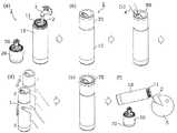
図1は、本実施の形態に係る蓋付きマグ1の斜視図である。図2は、本実施の形態に係る蓋付きマグ1の蓋部20を取り外した状態を示す斜視図である。なお、各図において、蓋付きマグ1の上下方向をz軸方向とし、当該上下方向に交差する2つの互いに直交する方向をx軸方向及びy軸方向とする。  FIG. 1 is a perspective view of a lidded mug 1 according to the present embodiment. FIG. 2 is a perspective view showing a state in which thelid portion 20 of the lidded mug 1 according to the present embodiment is removed. In addition, in each figure, let the up-down direction of the mug 1 with a lid | cover be the z-axis direction, and let two mutually orthogonal directions which cross | intersect the said up-down direction be an x-axis direction and a y-axis direction.

本実施の形態に係る蓋付きマグ1は、水などの液体を貯める容器(いわゆる水筒)であり、必要なタイミングで貯められた水を飲用水又は料理用水などとしてユーザに提供することができる。具体的には、蓋付きマグ1は、水道水、井戸水、湧き水、雨水などの水(以下、「未殺菌水」と記載する)に紫外線を照射することで殺菌する。蓋付きマグ1は、殺菌後の水(以下、「殺菌水」と記載する)を飲用水などとしてユーザに提供する。なお、未殺菌水とは、本実施の形態に係る蓋付きマグ1による殺菌を行う前の液体を意味し、他の手段によって殺菌済の液体も含む概念である。例えば、蓋付きマグ1には、市販のペットボトルの飲料水が入れられてもよい。  The lidded mug 1 according to the present embodiment is a container (so-called water bottle) for storing a liquid such as water, and can provide the user with the stored water as drinking water or cooking water. Specifically, the lidded mug 1 is sterilized by irradiating water such as tap water, well water, spring water, rain water (hereinafter referred to as “unsterilized water”) with ultraviolet rays. The lidded mug 1 provides the user with sterilized water (hereinafter referred to as “sterilized water”) as drinking water. In addition, unsterilized water means the liquid before sterilizing by the lid-mounted mug 1 which concerns on this Embodiment, and is a concept also including the liquid sterilized by other means. For example, drinking water from a commercially available plastic bottle may be placed in the lidded mug 1.

本実施の形態に係る蓋付きマグ1は、可搬性を有する。つまり、蓋付きマグ1は、小型、かつ、軽量であり、持ち運び可能である。蓋付きマグ1は、例えば、人が手で持てる大きさである。  The lidded mug 1 according to the present embodiment has portability. That is, the lidded mug 1 is small and lightweight and can be carried. The lidded mug 1 is, for example, a size that can be held by a person.

図2に示すように、蓋付きマグ1は、注水口と飲用口とを兼ねた開口部11を有する容器部10と、開口部11を塞ぐための蓋部20とを備える。蓋部20は、容器部10に対して着脱可能である。  As shown in FIG. 2, the lidded mug 1 includes acontainer portion 10 having anopening portion 11 serving as a water inlet and a drinking mouth, and alid portion 20 for closing theopening portion 11. Thelid part 20 is detachable from thecontainer part 10.

ユーザは、蓋付きマグ1の蓋部20を取り外して、開口部11を介して容器部10の内部に注水した後、蓋部20を取り付ける。蓋付きマグ1は、容器部10に貯められた水に紫外線を照射して、当該水を殺菌する。その後、ユーザは、蓋部20を取り外して、容器部10の内部に貯められた殺菌水を、開口部11を介して取り出し、飲用水などとして利用することができる。蓋付きマグ1の動作及び使用方法の詳細については、後で説明する。  The user removes thelid portion 20 of the lidded mug 1, pours water into thecontainer portion 10 through theopening 11, and then attaches thelid portion 20. The lidded mug 1 irradiates the water stored in thecontainer 10 with ultraviolet rays to sterilize the water. Thereafter, the user can remove thelid 20 and take out the sterilized water stored in thecontainer 10 through theopening 11 and use it as drinking water. Details of the operation and usage of the lidded mug 1 will be described later.

図3は、本実施の形態に係る蓋付きマグ1の分解斜視図である。なお、図3には、容器部10を示していない。図4は、本実施の形態に係る蓋付きマグ1の部分断面斜視図である。具体的には、図4は、図1のIV−IV線における断面を示している。  FIG. 3 is an exploded perspective view of the lidded mug 1 according to the present embodiment. In addition, thecontainer part 10 is not shown in FIG. FIG. 4 is a partial cross-sectional perspective view of the lidded mug 1 according to the present embodiment. Specifically, FIG. 4 shows a cross section taken along line IV-IV in FIG.

図3に示すように、蓋付きマグ1は、さらに、紫外線光源部30と、駆動回路部40と、バッテリー部50と、圧電素子60と、表示部70と、スイッチ部80とを備える。  As shown in FIG. 3, the lidded mug 1 further includes an ultravioletlight source unit 30, a drive circuit unit 40, abattery unit 50, apiezoelectric element 60, adisplay unit 70, and aswitch unit 80.

以下では、本実施の形態に係る蓋付きマグ1が備える各構成要素について、図1〜図4を適宜参照しながら詳細に説明する。  Below, each component with which the mug 1 with a cover which concerns on this Embodiment is provided is demonstrated in detail, referring FIGS. 1-4 suitably.

[容器部]
容器部10は、内部に液体が貯められる容器部である。容器部10は、内部に注液するための開口部11を有する。液体は、具体的には、水であるが、お茶又はジュースなどでもよい。
[Container]
Thecontainer part 10 is a container part in which a liquid is stored. Thecontainer part 10 has theopening part 11 for injecting liquid inside. The liquid is specifically water, but may be tea or juice.

開口部11は、注水口と飲用口とを兼ねている。なお、飲用口とは、具体的にはユーザが水を飲む際に直接、口を付ける部分を意味するが、これに限定されない。飲用口は、ユーザが飲むための水が取り出される給水口を意味する。つまり、ユーザが直接、口を付けることができるか否かは問われず、開口部11は、内部への注水と外部への給水との双方に利用される開口である。  The opening 11 serves as a water inlet and a drinking mouth. In addition, although a drinking mouth specifically means the part which attaches a mouth directly when a user drinks water, it is not limited to this. The drinking mouth means a water supply opening from which water for the user to drink is taken out. That is, regardless of whether or not the user can directly attach a mouth, theopening 11 is an opening that is used for both water injection to the inside and water supply to the outside.

本実施の形態では、容器部10は、開口部11以外に、内部への注水及び外部への給水を行うための開口を備えない。開口部11は、容器部10の内部と外部とを連通する唯一の開口である。  In this Embodiment, thecontainer part 10 is not provided with the opening for performing the water injection to an inside and the water supply to the exterior other than theopening part 11. FIG. The opening 11 is the only opening that communicates the inside and the outside of thecontainer 10.

容器部10の容量は、例えば500mLであるが、これに限定されない。容器部10は、例えば、人が片手又は両手で持てる程度の大きさである。  Although the capacity | capacitance of thecontainer part 10 is 500 mL, for example, it is not limited to this. Thecontainer unit 10 has a size that can be held by a person with one hand or both hands, for example.

容器部10の形状は、図1及び図2に示すように有底略円筒形状であるが、これに限定されない。容器部10の形状は、有底角筒形状でもよく、あるいは、開口部11が底部より小さい形状(いわゆるボトル状)でもよい。  Although the shape of thecontainer part 10 is a bottomed substantially cylindrical shape as shown in FIG.1 and FIG.2, it is not limited to this. The shape of thecontainer portion 10 may be a bottomed rectangular tube shape, or may be a shape in which theopening 11 is smaller than the bottom portion (so-called bottle shape).

本実施の形態では、容器部10は、保温機能を有する。具体的には、容器部10は、内側容器と外側容器との二重構造を有する。内側容器と外側容器との間は、真空などの減圧された空間である。これにより、内側容器と外側容器との間で熱伝導が抑制され、内部に貯められる液体の温度を保つことができる。  In this Embodiment, thecontainer part 10 has a heat retention function. Specifically, thecontainer part 10 has a double structure of an inner container and an outer container. The space between the inner container and the outer container is a decompressed space such as a vacuum. Thereby, heat conduction is suppressed between the inner container and the outer container, and the temperature of the liquid stored inside can be maintained.

容器部10の内側容器は、ステンレス又はアルミニウムなどの金属材料を用いて形成されている。これにより、容器部10の内面で紫外線光源部30が発する紫外線を反射させることができるので、効率良く水を殺菌することができる。なお、容器部10の外側容器は、例えば、ポリプロピレン(PP)などの樹脂材料から形成される。  The inner container of thecontainer part 10 is formed using metal materials, such as stainless steel or aluminum. Thereby, since the ultraviolet-ray which the ultravioletlight source part 30 emits can be reflected in the inner surface of thecontainer part 10, water can be disinfected efficiently. In addition, the outer container of thecontainer part 10 is formed from resin materials, such as a polypropylene (PP), for example.

なお、容器部10は、保温機能を有していなくてもよく、二重構造を有していなくてもよい。また、容器部10は、樹脂材料を用いて成形されて、その内面がめっき処理などによって金属材料で覆われていてもよい。  In addition, thecontainer part 10 does not need to have a heat retention function, and does not need to have a double structure. Moreover, thecontainer part 10 may be shape | molded using the resin material, and the inner surface may be covered with the metal material by the plating process etc.

[蓋部]
蓋部20は、開口部11を塞ぐための、容器部10に着脱可能な蓋部である。蓋部20は、容器部10に取り付けられることで、開口部11を塞ぐことができる。
[Cover]
Thelid 20 is a lid that can be attached to and detached from thecontainer 10 to close theopening 11. Thelid part 20 can close theopening 11 by being attached to thecontainer part 10.

蓋部20が容器部10に取り付けられた状態、すなわち、蓋部20が開口部11を塞いだ状態では、蓋部20と開口部11との間には隙間は形成されておらず、容器部10の内部から外部に光(紫外線)は漏れない。また、蓋部20が開口部11を塞いだ状態では、容器部10に貯められた水は、外部に漏れ出ない。  In a state where thelid portion 20 is attached to thecontainer portion 10, that is, in a state where thelid portion 20 blocks the openingportion 11, no gap is formed between thelid portion 20 and the openingportion 11. Light (ultraviolet rays) does not leak from the inside of the 10 to the outside. Further, in the state where thelid 20 closes theopening 11, the water stored in thecontainer 10 does not leak to the outside.

本実施の形態では、蓋部20は、ネジ式の蓋である。具体的には、蓋部20には雌ねじが設けられ、当該雌ねじに螺合する雄ねじが容器部10の開口部11の近傍に設けられている。蓋部20を容器部10に対して回動させることで、蓋部20は、容器部10に取り付けられて開口部11を塞ぐことができる。なお、蓋部20の回動軸は、円筒形状の蓋付きマグ1の中心軸(z軸方向)である。  In the present embodiment, thelid 20 is a screw-type lid. Specifically, thelid portion 20 is provided with a female screw, and a male screw that engages with the female screw is provided in the vicinity of theopening 11 of thecontainer portion 10. By rotating thelid portion 20 with respect to thecontainer portion 10, thelid portion 20 can be attached to thecontainer portion 10 and block theopening 11. The rotation axis of thelid 20 is the central axis (z-axis direction) of the cylindrical lidded mug 1.

なお、蓋部20は、押し込み式又はスライド式などの蓋でもよく、容器部10への取り付け方式は特に限定されない。例えば、蓋部20は、容器部10の開口部11に対して押し込むことで容器部10に取り付けられてもよい。  Thelid 20 may be a push-type or slide-type lid, and the attachment method to thecontainer 10 is not particularly limited. For example, thelid portion 20 may be attached to thecontainer portion 10 by being pushed into the openingportion 11 of thecontainer portion 10.

蓋部20の形状は、図1及び図2に示すように、両端が閉じられた略円筒形状であるが、これに限定されない。蓋部20の形状は、容器部10の開口部11の形状に対応し、開口部11を塞ぐことができる形状である。  As shown in FIGS. 1 and 2, the shape of thelid 20 is a substantially cylindrical shape with both ends closed, but is not limited thereto. The shape of thelid portion 20 corresponds to the shape of the openingportion 11 of thecontainer portion 10 and is a shape that can close the openingportion 11.

図2及び図4に示される蓋部20の裏面20aは、容器部10の開口部11を塞ぐための面である。図3及び図4に示される蓋部20の表面20bは、裏面20aの反対側の面である。なお、本実施の形態では、蓋部20が容器部10に取り付けられた状態(図4参照)において裏面20aから表面20bに向かう方向、すなわち、z軸正方向を「上方」と記載し、その反対方向を「下方」と記載する場合がある。  Theback surface 20a of thelid 20 shown in FIGS. 2 and 4 is a surface for closing theopening 11 of thecontainer 10. Thefront surface 20b of thelid 20 shown in FIGS. 3 and 4 is a surface opposite to theback surface 20a. In the present embodiment, the direction from theback surface 20a to thefront surface 20b in the state where thelid portion 20 is attached to the container portion 10 (see FIG. 4), that is, the z-axis positive direction is described as “upward”. The opposite direction may be described as “downward”.

図3に示すように、蓋部20は、蓋ベース21と、電池蓋22と、密閉パッキン23と、防水パッキン24とを備える。  As shown in FIG. 3, thelid portion 20 includes alid base 21, abattery lid 22, a sealing packing 23, and awaterproof packing 24.

蓋ベース21は、蓋部20の本体である。蓋ベース21の形状は、有底略円筒形状である。図2に示すように、蓋ベース21の底部211の外面が蓋部20の裏面20aである。蓋ベース21と電池蓋22とが組み合わされて略円筒形状の蓋部20の外郭が形成される。蓋ベース21は、例えば、ポリプロピレンなどの樹脂材料から形成される。  Thelid base 21 is a main body of thelid portion 20. The shape of thelid base 21 is a bottomed substantially cylindrical shape. As shown in FIG. 2, the outer surface of thebottom portion 211 of thelid base 21 is aback surface 20 a of thelid portion 20. Thecover base 21 and thebattery cover 22 are combined to form the outer shape of the substantiallycylindrical cover 20. Thelid base 21 is made of a resin material such as polypropylene, for example.

本実施の形態では、図4に示すように、底部211には、容器部10の開口部11に合わせて凹凸が設けられている。つまり、底部211は、凹部212と、凸部213とを有する。凹部212は、蓋ベース21の外周に沿って設けられた環状の凹部(溝)である。凸部213は、周囲を凹部212に囲まれた略円柱状の凸部であり、下方(z軸方向の負側)に向けて突出している。  In the present embodiment, as shown in FIG. 4, thebottom portion 211 is provided with irregularities in accordance with the openingportion 11 of thecontainer portion 10. That is, thebottom portion 211 has theconcave portion 212 and theconvex portion 213. Therecess 212 is an annular recess (groove) provided along the outer periphery of thelid base 21. Theconvex portion 213 is a substantially cylindrical convex portion surrounded by theconcave portion 212 and protrudes downward (on the negative side in the z-axis direction).

凹部212には、容器部10の開口部11の縁が挿入される。本実施の形態では、凹部212には、雌ねじが設けられており、開口部11の縁の外側面に設けられた雄ねじと螺合する。  The edge of theopening 11 of thecontainer part 10 is inserted into therecess 212. In the present embodiment, therecess 212 is provided with a female screw and is screwed with a male screw provided on the outer surface of the edge of theopening 11.

凸部213は、蓋部20が容器部10に取り付けられた場合に、開口部11を介して挿入されて容器部10の内方に位置する。本実施の形態では、図2に示すように、凸部213に紫外線光源部30が取り付けられている。  Theconvex portion 213 is inserted through the openingportion 11 and located inside thecontainer portion 10 when thelid portion 20 is attached to thecontainer portion 10. In the present embodiment, as shown in FIG. 2, the ultravioletlight source unit 30 is attached to theconvex portion 213.

具体的には、図4に示すように、凸部213には、略中央部分にz軸方向に貫通する孔部214が設けられている。紫外線光源部30のUVランプ31が孔部214に挿入されて取り付けられている。孔部214の内面には、雌ねじが設けられており、UVランプ31の外周に設けられた雄ねじと螺合する。  Specifically, as shown in FIG. 4, theconvex portion 213 is provided with ahole portion 214 penetrating in the z-axis direction at a substantially central portion. TheUV lamp 31 of the ultravioletlight source unit 30 is inserted into thehole 214 and attached. A female screw is provided on the inner surface of thehole 214 and is screwed with a male screw provided on the outer periphery of theUV lamp 31.

なお、裏面20aは、例えば、金属面である。具体的には、凸部213の下面は、例えばアルミニウムなどの金属膜で覆われている。これにより、紫外線光源部30が発する紫外線を反射させることができるので、効率良く水を殺菌することができる。なお、蓋ベース21がステンレス又はアルミニウムなどの金属材料を用いて形成されてもよい。  Theback surface 20a is, for example, a metal surface. Specifically, the lower surface of theprojection 213 is covered with a metal film such as aluminum. Thereby, since the ultraviolet-ray which the ultraviolet-raylight source part 30 emits can be reflected, water can be sterilized efficiently. Thelid base 21 may be formed using a metal material such as stainless steel or aluminum.

電池蓋22は、蓋ベース21の開口を覆う蓋である。電池蓋22の形状は、扁平な有底略円筒形状である。図3に示すように、電池蓋22の底部221の外面が蓋部20の表面20bである。電池蓋22は、例えば、ポリプロピレンなどの樹脂材料から形成される。  Thebattery lid 22 is a lid that covers the opening of thelid base 21. The shape of thebattery lid 22 is a flat bottomed substantially cylindrical shape. As shown in FIG. 3, the outer surface of thebottom portion 221 of thebattery lid 22 is asurface 20 b of thelid portion 20. Thebattery lid 22 is formed from a resin material such as polypropylene, for example.

本実施の形態では、図4に示すように、底部221の内面(表面20bの反対側の面)から突起部222が下方に向けて立設している。上面視において、突起部222の周囲には一部を除いてスリットが設けられており、突起部222は、z軸方向に移動可能である。図4に示すように、突起部222の上面にスイッチ部80が固定されている。突起部222は、スイッチ部80が押下(オン)されたときに下方に移動して、駆動回路部40のスイッチ素子42を押下する。  In the present embodiment, as shown in FIG. 4, theprotrusion 222 is erected downward from the inner surface of the bottom portion 221 (the surface opposite to thesurface 20 b). When viewed from above, a slit is provided around theprotrusion 222 except for a part thereof, and theprotrusion 222 is movable in the z-axis direction. As shown in FIG. 4, theswitch unit 80 is fixed to the upper surface of theprotrusion 222. Theprotrusion 222 moves downward when theswitch unit 80 is pressed (turned on), and presses theswitch element 42 of the drive circuit unit 40.

電池蓋22は、例えば、蓋ベース21に対して着脱可能でもよい。例えば、電池蓋22は、ネジ式の蓋である。これにより、電池蓋22を容易に蓋ベース21から取り外すことで、バッテリー部50(具体的には、電池51)の交換を行うことができる。  Thebattery lid 22 may be detachable from thelid base 21, for example. For example, thebattery lid 22 is a screw-type lid. Accordingly, the battery cover 50 (specifically, the battery 51) can be replaced by easily removing thebattery cover 22 from thecover base 21.

密閉パッキン23は、図4に示すように、蓋部20の裏面20a側に設けられている。具体的には、密閉パッキン23は、蓋ベース21の凸部213の外面に固定されている。図3に示すように、密閉パッキン23の形状は、略円筒形状である。密閉パッキン23は、例えば耐水性を有するゴムなどの樹脂材料から形成される。  As shown in FIG. 4, the sealing packing 23 is provided on theback surface 20 a side of thelid portion 20. Specifically, the sealing packing 23 is fixed to the outer surface of theconvex portion 213 of thelid base 21. As shown in FIG. 3, the shape of the sealing packing 23 is a substantially cylindrical shape. The sealing packing 23 is made of a resin material such as rubber having water resistance, for example.

密閉パッキン23は、蓋部20が容器部10に取り付けられた場合に、蓋部20と容器部10との間の隙間を塞ぐ。具体的には、密閉パッキン23は、開口部11と凸部213との間を塞ぐ。これにより、蓋部20が開口部11を完全に塞ぐことができ、容器部10の内部から水及び光が外部に漏れないようすることができる。  Thehermetic packing 23 closes the gap between thelid 20 and thecontainer 10 when thelid 20 is attached to thecontainer 10. Specifically, the sealing packing 23 closes between theopening 11 and theconvex portion 213. Thereby, thecover part 20 can block | close the openingpart 11 completely, and it can prevent that water and light leak from the inside of thecontainer part 10 outside.

防水パッキン24は、図4に示すように、蓋ベース21と電池蓋22との間に設けられている。図3に示すように、防水パッキン24の形状は、略円環形状である。防水パッキン24は、例えば耐水性を有するゴムなどの樹脂材料から形成される。  As shown in FIG. 4, thewaterproof packing 24 is provided between thelid base 21 and thebattery lid 22. As shown in FIG. 3, thewaterproof packing 24 has a substantially annular shape. Thewaterproof packing 24 is formed of a resin material such as rubber having water resistance, for example.

防水パッキン24は、蓋ベース21と電池蓋22との間の隙間を介して水分が蓋ベース21の内部に進入するのを抑制する。これにより、蓋部20の内部に収容される駆動回路部40及びバッテリー部50などを水分から保護することができる。  Thewaterproof packing 24 suppresses moisture from entering the inside of thelid base 21 through the gap between thelid base 21 and thebattery lid 22. Thereby, the drive circuit part 40, thebattery part 50, etc. which are accommodated in the inside of thecover part 20 can be protected from moisture.

[紫外線光源部]
紫外線光源部30は、容器部10の内部に配置される。本実施の形態では、紫外線光源部30は、蓋部20の裏面20a側に取り付けられている。このため、紫外線光源部30は、蓋部20が容器部10に取り付けられた場合に、容器部10の内部に配置される。また、図2に示すように、蓋部20が容器部10から取り外された場合に、蓋部20と紫外線光源部30とは一体的に容器部10から取り外される。
[Ultraviolet light source]
The ultravioletlight source unit 30 is disposed inside thecontainer unit 10. In the present embodiment, the ultravioletlight source unit 30 is attached to theback surface 20 a side of thelid unit 20. For this reason, the ultravioletlight source part 30 is arrange | positioned inside thecontainer part 10, when thecover part 20 is attached to thecontainer part 10. FIG. As shown in FIG. 2, when thelid part 20 is removed from thecontainer part 10, thelid part 20 and the ultravioletlight source part 30 are integrally removed from thecontainer part 10.

紫外線光源部30は、容器部10に貯められる液体(具体的には、水)に紫外線を照射することで、当該液体を殺菌する。照射する紫外線は、例えば、200nm〜400nmの範囲にピーク波長を有する紫外線である。本実施の形態では、紫外線光源部30は、一例として、ピーク波長が253.7nmの紫外線を照射する。  The ultravioletlight source unit 30 sterilizes the liquid by irradiating the liquid (specifically, water) stored in thecontainer unit 10 with ultraviolet rays. The ultraviolet rays to be irradiated are, for example, ultraviolet rays having a peak wavelength in the range of 200 nm to 400 nm. In the present embodiment, the ultravioletlight source unit 30 irradiates ultraviolet rays having a peak wavelength of 253.7 nm as an example.

図3に示すように、紫外線光源部30は、UVランプ31と、保護枠32と、ネジ33と、Oリング34とを備える。  As shown in FIG. 3, the ultravioletlight source unit 30 includes aUV lamp 31, aprotective frame 32, ascrew 33, and an O-ring 34.

UVランプ31は、駆動回路部40から電力を受けて紫外線を発する。UVランプ31としては、例えば、入力電力3Wのグロー電球(紫外線出力1W)を用いることができるが、これに限定されない。UVランプ31は、紫外線を発するLED(Light Emitting Diode)素子を用いてもよい。  TheUV lamp 31 receives electric power from the drive circuit unit 40 and emits ultraviolet rays. As theUV lamp 31, for example, a glow light bulb (ultraviolet light output 1W) with an input power of 3W can be used, but is not limited thereto. TheUV lamp 31 may use an LED (Light Emitting Diode) element that emits ultraviolet rays.

UVランプ31は、裏面20aを貫通するように設けられている。具体的には、UVランプ31は、孔部214にねじ入れられて固定されている。なお、UVランプ31は、蓋ベース21に取り付けられた後、防水のために樹脂などを用いて固着されてもよい。  TheUV lamp 31 is provided so as to penetrate theback surface 20a. Specifically, theUV lamp 31 is screwed into thehole 214 and fixed. TheUV lamp 31 may be fixed to thelid base 21 using a resin or the like for waterproofing.

UVランプ31は、下面視において裏面20aの略中心に設けられている。これにより、容器部10に貯められた水に、略均等に紫外線を照射することができる。  TheUV lamp 31 is provided substantially at the center of theback surface 20a when viewed from below. Thereby, it is possible to irradiate the water stored in thecontainer part 10 with ultraviolet rays substantially evenly.

UVランプ31及び保護枠32は、蓋部20が容器部10に取り付けられた場合に、図4に示すように、開口部11から挿入されて容器部10の内部に位置している。これにより、UVランプ31及び保護枠32は、容器部10に規定の水量(例えば500mL)の水が貯められた場合に、貯められた水に浸かる。  As shown in FIG. 4, theUV lamp 31 and theprotective frame 32 are inserted from theopening 11 and positioned inside thecontainer part 10 when thelid part 20 is attached to thecontainer part 10. Thereby, theUV lamp 31 and theprotective frame 32 are immersed in the stored water when a predetermined amount of water (for example, 500 mL) is stored in thecontainer unit 10.

保護枠32は、UVランプ31の破損を防止するための立体格子状のカバーである。保護枠32は、UVランプ31を囲むように設けられている。保護枠32は、例えばステンレスなどの金属材料から形成される。  Theprotective frame 32 is a three-dimensional lattice-shaped cover for preventing theUV lamp 31 from being damaged. Theprotective frame 32 is provided so as to surround theUV lamp 31. Theprotective frame 32 is made of a metal material such as stainless steel, for example.

ネジ33は、保護枠32を蓋ベース21(具体的には、凸部213)に固定するためのネジであり、例えば、タッピンネジである。  Thescrew 33 is a screw for fixing theprotective frame 32 to the lid base 21 (specifically, the convex portion 213), and is, for example, a tapping screw.

Oリング34は、図4に示すように、UVランプ31と蓋部20(具体的には、孔部214)との間に設けられている。図3に示すように、Oリング34の形状は、略円環形状である。Oリング34は、例えば耐水性を有するゴムなどの樹脂材料から形成される。Oリング34は、UVランプ31と孔部214との間の隙間を介して水分が蓋部20の内部に進入するのを抑制する。これにより、蓋部20の内部に位置するUVランプ31の給電部分、駆動回路部40及びバッテリー部50などを水分から保護することができる。  As shown in FIG. 4, the O-ring 34 is provided between theUV lamp 31 and the lid 20 (specifically, the hole 214). As shown in FIG. 3, the shape of the O-ring 34 is a substantially annular shape. The O-ring 34 is formed from a resin material such as rubber having water resistance, for example. The O-ring 34 prevents moisture from entering the inside of thelid 20 through the gap between theUV lamp 31 and thehole 214. Thereby, the electric power feeding part of theUV lamp 31 located inside thecover part 20, the drive circuit part 40, thebattery part 50, etc. can be protected from moisture.

[駆動回路部]
駆動回路部40は、蓋部20の内部に収納され、紫外線光源部30の点灯及び消灯を制御する。具体的には、駆動回路部40は、紫外線光源部30を点灯するタイミング及び消灯するタイミングを制御する。なお、駆動回路部40は、紫外線光源部30が出射する紫外線の強度、又は、紫外線を照射する期間を変更する制御を行ってもよい。
[Drive circuit section]
The drive circuit unit 40 is housed inside thelid unit 20 and controls turning on and off of the ultravioletlight source unit 30. Specifically, the drive circuit unit 40 controls the timing for turning on and off the ultravioletlight source unit 30. Note that the drive circuit unit 40 may perform control to change the intensity of the ultraviolet light emitted from the ultravioletlight source unit 30 or the period of irradiation with the ultraviolet light.

駆動回路部40は、圧電素子60が発電した電力を用いて紫外線光源部30を点灯させる。具体的には、駆動回路部40は、バッテリー部50に蓄積された電力を用いて紫外線光源部30を点灯させる。なお、圧電素子60が発電した電力は、バッテリー部50に蓄積される。  The drive circuit unit 40 turns on the ultravioletlight source unit 30 using the electric power generated by thepiezoelectric element 60. Specifically, the drive circuit unit 40 turns on the ultravioletlight source unit 30 using the electric power stored in thebattery unit 50. The electric power generated by thepiezoelectric element 60 is stored in thebattery unit 50.

本実施の形態では、駆動回路部40は、紫外線光源部30の点灯が可能な点灯可能モードと、紫外線光源部30の点灯が禁止されている点灯禁止モードとを実行する。点灯可能モードでは、スイッチ部80がオンされたときに、駆動回路部40は、紫外線光源部30の点灯を行う。点灯禁止モードでは、スイッチ部80がオンされたとしても、駆動回路部40は、紫外線光源部30の点灯を行わない。  In the present embodiment, the drive circuit unit 40 executes a lighting enabled mode in which the ultravioletlight source unit 30 can be turned on and a lighting prohibited mode in which lighting of the ultravioletlight source unit 30 is prohibited. In the lighting enabled mode, the drive circuit unit 40 turns on the ultravioletlight source unit 30 when theswitch unit 80 is turned on. In the lighting prohibition mode, the drive circuit unit 40 does not turn on the ultravioletlight source unit 30 even if theswitch unit 80 is turned on.

本実施の形態では、駆動回路部40は、図示しない開閉センサ又は水位センサなどに基づいて、点灯可能モードと点灯禁止モードとを切り替える。  In the present embodiment, the drive circuit unit 40 switches between the lighting enabled mode and the lighting prohibited mode based on an opening / closing sensor or a water level sensor (not shown).

例えば、開閉センサは、蓋部20が容器部10に正しく取り付けられているか否かを検知する。駆動回路部40は、蓋部20が容器部10に正しく取り付けられている場合、点灯可能モードを実行する。また、駆動回路部40は、蓋部20が容器部10から取り外されている場合、及び、蓋部20が容器部10に正しく取り付けられていない場合、点灯禁止モードを実行する。  For example, the open / close sensor detects whether or not thelid portion 20 is correctly attached to thecontainer portion 10. The drive circuit unit 40 executes the lighting enabled mode when thelid unit 20 is correctly attached to thecontainer unit 10. In addition, when thelid 20 is removed from thecontainer unit 10 and when thelid 20 is not correctly attached to thecontainer unit 10, the drive circuit unit 40 executes the lighting prohibition mode.

また、例えば、水位センサは、容器部10の内部に液体(例えば、水)が所定量(例えば、500mL)貯められているか否かを検知する。駆動回路部40は、容器部10の内部に所定量の水が貯められている場合に、点灯可能モードを実行する。また、駆動回路部40は、容器部10の内部に所定量の水が貯められていない場合に、点灯禁止モードを実行する。  Further, for example, the water level sensor detects whether or not a predetermined amount (for example, 500 mL) of liquid (for example, water) is stored in thecontainer unit 10. The drive circuit unit 40 executes the lightable mode when a predetermined amount of water is stored in thecontainer unit 10. Further, the drive circuit unit 40 executes the lighting prohibition mode when a predetermined amount of water is not stored in thecontainer unit 10.

図3に示すように、駆動回路部40は、メイン回路基板41と、スイッチ素子42と、LED基板43と、ネジ44とを備える。  As shown in FIG. 3, the drive circuit unit 40 includes amain circuit board 41, aswitch element 42, anLED board 43, and screws 44.

メイン回路基板41は、紫外線光源部30(具体的には、UVランプ31)の点灯及び消灯を制御する。つまり、メイン回路基板41は、バッテリー部50又は圧電素子60からUVランプ31への電力の供給の開始及び停止を制御するための回路基板である。メイン回路基板41は、例えば、マイコン(マイクロコントローラ)が実装された基板である。  Themain circuit board 41 controls lighting and extinguishing of the ultraviolet light source unit 30 (specifically, the UV lamp 31). That is, themain circuit board 41 is a circuit board for controlling the start and stop of power supply from thebattery unit 50 or thepiezoelectric element 60 to theUV lamp 31. Themain circuit board 41 is, for example, a board on which a microcomputer (microcontroller) is mounted.

メイン回路基板41は、スイッチ素子42からの制御信号に基づいて動作する。また、メイン回路基板41は、開閉センサ又は水位センサに基づいて、点灯可能モードと点灯禁止モードとを切り替える。  Themain circuit board 41 operates based on a control signal from theswitch element 42. Further, themain circuit board 41 switches between the lighting enabled mode and the lighting prohibited mode based on the open / close sensor or the water level sensor.

点灯可能モードの場合に、スイッチ部80がオンされたとき、メイン回路基板41は、予め定められた期間、紫外線光源部30を点灯させる。なお、当該期間は、容器部10に入れられた未殺菌水が殺菌されるのに十分な期間である。当該期間は、例えば、容器部10の容量と紫外線光源部30の紫外線の強度とに基づいて決定された期間である。  When theswitch unit 80 is turned on in the lighting enabled mode, themain circuit board 41 turns on the ultravioletlight source unit 30 for a predetermined period. In addition, the said period is a period sufficient for the unsterilized water put into thecontainer part 10 to be sterilized. The said period is a period determined based on the capacity | capacitance of thecontainer part 10 and the intensity | strength of the ultraviolet-ray of the ultravioletlight source part 30, for example.

スイッチ素子42は、スイッチ部80の押下(オン)を検出し、制御信号をメイン回路基板41に出力する。スイッチ素子42は、例えば、LED基板43に実装されている。  Theswitch element 42 detects the pressing (ON) of theswitch unit 80 and outputs a control signal to themain circuit board 41. Theswitch element 42 is mounted on theLED board 43, for example.

本実施の形態では、スイッチ素子42は、スイッチ部80がオンされたことを検出した場合に、UVランプ31の点灯を開始するためのオン信号を制御信号としてメイン回路基板41に出力する。メイン回路基板41は、オン信号が入力された場合に、点灯可能モードであれば、UVランプ31を点灯させる。  In the present embodiment, when detecting that theswitch unit 80 is turned on, theswitch element 42 outputs an ON signal for starting lighting of theUV lamp 31 to themain circuit board 41 as a control signal. When the ON signal is input, themain circuit board 41 turns on theUV lamp 31 in the lighting-enabled mode.

LED基板43は、LED素子(図示せず)が実装された基板である。LED素子は、可視光を発する。LED素子が発した光は、表示部70を透過して外部に出射する。  TheLED substrate 43 is a substrate on which an LED element (not shown) is mounted. The LED element emits visible light. The light emitted from the LED element passes through thedisplay unit 70 and is emitted to the outside.

本実施の形態では、LED基板43は、UVランプ31の点灯状態に応じてLED素子の点灯を制御する。具体的には、LED基板43は、UVランプ31の点灯中、すなわち、UVランプ31が紫外線を発している期間に、LED素子を点滅点灯させる。また、LED基板43は、UVランプ31の点灯終了後に、LED素子を連続点灯させる。  In the present embodiment, theLED substrate 43 controls the lighting of the LED elements according to the lighting state of theUV lamp 31. Specifically, theLED board 43 blinks the LED elements while theUV lamp 31 is lit, that is, during the period when theUV lamp 31 emits ultraviolet rays. In addition, theLED substrate 43 continuously turns on the LED elements after theUV lamp 31 is turned on.

さらに、LED基板43は、UVランプ31の点灯終了後に蓋部20が容器部10から取り外された場合に、LED素子を消灯する。例えば、LED基板43は、開閉センサに電気的に接続されており、開閉センサによって蓋部20が容器部10から取り外されたことが検知されたときに、LED素子を消灯する。  Furthermore, theLED substrate 43 turns off the LED element when thelid 20 is removed from thecontainer 10 after theUV lamp 31 is turned on. For example, theLED substrate 43 is electrically connected to an open / close sensor, and turns off the LED element when the open / close sensor detects that thelid 20 has been removed from thecontainer 10.

ネジ44は、メイン回路基板41を蓋ベース21に固定するためのネジであり、例えば、タッピンネジである。なお、本実施の形態では、メイン回路基板41は、2つのネジ44と2つのネジ54とによって蓋ベース21の底部211に固定されている。LED基板43は、例えば、蓋ベース21の内部に設けられた突起(図示せず)に載置されている。  Thescrew 44 is a screw for fixing themain circuit board 41 to thelid base 21 and is, for example, a tapping screw. In the present embodiment, themain circuit board 41 is fixed to thebottom portion 211 of thelid base 21 with twoscrews 44 and twoscrews 54. For example, theLED substrate 43 is placed on a protrusion (not shown) provided inside thelid base 21.

[バッテリー部]
バッテリー部50は、蓋部20の内部に収納され、紫外線光源部30に電力を供給するためのバッテリー部である。本実施の形態では、バッテリー部50は、駆動回路部40に電力を供給することで、紫外線光源部30だけでなく、表示部70のLED素子などにも電力を供給する。
[Battery section]
Thebattery unit 50 is a battery unit that is housed inside thelid unit 20 and supplies power to the ultravioletlight source unit 30. In the present embodiment, thebattery unit 50 supplies power not only to the ultravioletlight source unit 30 but also to the LED elements of thedisplay unit 70 by supplying power to the drive circuit unit 40.

図3に示すように、バッテリー部50は、電池51と、2つの電池端子52と、電池受け53と、ネジ54とを備える。  As shown in FIG. 3, thebattery unit 50 includes abattery 51, twobattery terminals 52, abattery receiver 53, and ascrew 54.

電池51は、駆動回路部40に電力を供給する電源の一例である。電池51は、例えば、圧電素子60が発電した電力を蓄積する蓄電池の一例である。電池51は、例えばリチウムイオン電池などの二次電池であるが、これに限定されない。なお、電池51は、圧電素子60からの電力だけでなく、蓋付きマグ1の外部から供給された電力を蓄積してもよい。例えば、蓋付きマグ1が電池51の充電用の端子などを備えていてもよく、当該端子を介して外部から供給された電力を電池51が蓄積してもよい。  Thebattery 51 is an example of a power source that supplies power to the drive circuit unit 40. Thebattery 51 is an example of a storage battery that stores electric power generated by thepiezoelectric element 60. Thebattery 51 is a secondary battery such as a lithium ion battery, but is not limited thereto. Thebattery 51 may store not only the electric power from thepiezoelectric element 60 but also the electric power supplied from the outside of the lidded mug 1. For example, the lidded mug 1 may include a terminal for charging thebattery 51 and the like, and thebattery 51 may store electric power supplied from the outside through the terminal.

2つの電池端子52は、一方が電池51の正極に接触し、他方が電池51の負極に接触するように配置されている。2つの電池端子52は、例えば、金属などの導電性材料を用いて形成されている。2つの電池端子52は、電池51の電力を駆動回路部40に供給する。  The twobattery terminals 52 are arranged such that one contacts the positive electrode of thebattery 51 and the other contacts the negative electrode of thebattery 51. The twobattery terminals 52 are formed using a conductive material such as metal, for example. The twobattery terminals 52 supply the power of thebattery 51 to the drive circuit unit 40.

電池受け53は、電池51を支持するための部材である。電池受け53は、例えば、絶縁性の樹脂材料を用いて形成される。本実施の形態では、電池受け53は、電池51の約半分が収容される凹部を有している。電池51は、当該凹部に収容され、上部を電池蓋22に押さえられている。これにより、蓋部20の内部での電池51の移動が規制され、駆動回路部40への電力の供給の信頼性を高めることができる。  Thebattery receiver 53 is a member for supporting thebattery 51. Thebattery receiver 53 is formed using, for example, an insulating resin material. In the present embodiment, thebattery receiver 53 has a recess in which about half of thebattery 51 is accommodated. Thebattery 51 is accommodated in the recess, and the upper part is held by thebattery lid 22. Thereby, the movement of thebattery 51 inside thelid portion 20 is restricted, and the reliability of power supply to the drive circuit portion 40 can be improved.

ネジ54は、電池受け53を蓋部20に固定するためのネジである。本実施の形態では、図4に示すように、ネジ54は、電池受け53と蓋ベース21との間にメイン回路基板41を挟んで固定している。ネジ54は、例えば、タッピンネジである。  Thescrew 54 is a screw for fixing thebattery receiver 53 to thelid portion 20. In the present embodiment, as shown in FIG. 4, thescrew 54 is fixed by sandwiching themain circuit board 41 between thebattery receiver 53 and thelid base 21. Thescrew 54 is, for example, a tapping screw.

なお、電池51は、着脱可能でもよい。すなわち、本実施の形態では、電池51を交換可能でもよい。これにより、電池51の容量が少なくなった(あるいは、なくなった)ときに、容量が少ない電池51を新しい電池51に取り替えることができる。例えば、電池蓋22を蓋ベース21から取り外すことで、電池51が外部に露出するので、容易に電池51の交換を行うことができる。  Thebattery 51 may be detachable. That is, in the present embodiment, thebattery 51 may be replaceable. Thereby, when the capacity of thebattery 51 becomes small (or disappears), thebattery 51 having a small capacity can be replaced with anew battery 51. For example, since thebattery 51 is exposed to the outside by removing thebattery lid 22 from thelid base 21, thebattery 51 can be easily replaced.

[圧電素子]
圧電素子(ピエゾ素子)60は、容器部10又は蓋部20に設けられている。本実施の形態では、圧電素子60は、容器部10の液体が貯められる空間に露出して配置されている。具体的には、図4に示すように、圧電素子60は、蓋部20の裏面20aに取り付けられている。
[Piezoelectric element]
The piezoelectric element (piezo element) 60 is provided in thecontainer part 10 or thelid part 20. In the present embodiment, thepiezoelectric element 60 is disposed so as to be exposed to a space in which the liquid in thecontainer portion 10 is stored. Specifically, as shown in FIG. 4, thepiezoelectric element 60 is attached to theback surface 20 a of thelid portion 20.

圧電素子60は、力が加えられたときに発電する素子である。本実施の形態では、圧電素子60は、蓋付きマグ1を振ったときに内部で移動する液体の力を利用して発電する。  Thepiezoelectric element 60 is an element that generates electric power when a force is applied. In the present embodiment, thepiezoelectric element 60 generates electric power by using the force of the liquid that moves inside when the lidded mug 1 is shaken.

図5は、本実施の形態に係る蓋付きマグ1を振ったときの内部の様子を模式的に示す断面図である。図5の(a)は、蓋付きマグ1が静止中(例えば、机の上などに置かれている場合)の内部の様子を示している。図5の(b)は、蓋付きマグ1を振ったときの内部の様子を示している。  FIG. 5 is a cross-sectional view schematically showing an internal state when the lidded mug 1 according to the present embodiment is shaken. (A) of FIG. 5 has shown the mode of the inside when the mug 1 with a lid | cover is stationary (for example, when placed on the desk etc.). FIG. 5B shows an internal state when the lidded mug 1 is shaken.

図5の(b)に示すように、蓋付きマグ1を振ったときに、内部で液体2が移動する。圧電素子60は、容器部10の液体2が貯められる空間10aに露出しているので、蓋付きマグ1を振ったときに内部の液体2が圧電素子60に当たる。圧電素子60は、液体2が当たったときの力を利用して発電する。  As shown in FIG. 5B, when the lidded mug 1 is shaken, theliquid 2 moves inside. Since thepiezoelectric element 60 is exposed to thespace 10 a in which theliquid 2 in thecontainer portion 10 is stored, theliquid 2 inside hits thepiezoelectric element 60 when the lidded mug 1 is shaken. Thepiezoelectric element 60 generates electric power using the force when the liquid 2 hits it.

これにより、液体2を撹拌させながら、圧電素子60による発電を行うことができる。つまり、液体2の撹拌と殺菌(紫外線光源部30からの紫外線の照射)とを同時に行うことができる。  Thereby, the electric power generation by thepiezoelectric element 60 can be performed while stirring theliquid 2. That is, stirring and sterilization (irradiation of ultraviolet rays from the ultraviolet light source unit 30) of the liquid 2 can be performed simultaneously.

図示しないが、圧電素子60は、リード線などの導線を介して、駆動回路部40に電気的に接続されている。圧電素子60は、発電した電力を駆動回路部40に供給する。駆動回路部40は、圧電素子60から供給された電力をUVランプ31に供給することで、紫外線を照射させる。あるいは、駆動回路部40は、圧電素子60から供給された電力を電池51に蓄積させてもよい。  Although not shown, thepiezoelectric element 60 is electrically connected to the drive circuit unit 40 via a conducting wire such as a lead wire. Thepiezoelectric element 60 supplies the generated power to the drive circuit unit 40. The drive circuit unit 40 supplies the power supplied from thepiezoelectric element 60 to theUV lamp 31 to irradiate ultraviolet rays. Alternatively, the drive circuit unit 40 may store the power supplied from thepiezoelectric element 60 in thebattery 51.

[表示部]
表示部70は、紫外線光源部30の点灯状態を表示する。本実施の形態では、表示部70は、略円環状の樹脂部材である。具体的には、表示部70は、シリカなどの拡散材料が内部に拡散された透光性の樹脂材料を用いた射出成形により形成される。例えば、表示部70は、二色成形により電池蓋22と一体に形成される。
[Display section]
Thedisplay unit 70 displays the lighting state of the ultravioletlight source unit 30. In the present embodiment,display unit 70 is a substantially annular resin member. Specifically, thedisplay unit 70 is formed by injection molding using a translucent resin material in which a diffusion material such as silica is diffused. For example, thedisplay unit 70 is formed integrally with thebattery lid 22 by two-color molding.

表示部70は、LED基板43のLED素子が発した光を透過させ、かつ、拡散材料によって拡散(散乱)させる。紫外線光源部30(具体的にはUVランプ31)の点灯状態に応じてLED素子の点灯状態が変化するので、表示部70は、UVランプ31の点灯状態を表示することができる。  Thedisplay unit 70 transmits light emitted from the LED elements of theLED substrate 43 and diffuses (scatters) the light using a diffusing material. Since the lighting state of the LED element changes according to the lighting state of the ultraviolet light source unit 30 (specifically, the UV lamp 31), thedisplay unit 70 can display the lighting state of theUV lamp 31.

具体的には、表示部70は、紫外線光源部30の点灯中に点滅点灯し、紫外線光源部30の点灯終了後に連続点灯する。点滅点灯は、光量の増減を繰り返すことであり、例えば、点灯(100%)と消灯(0%)とを繰り返すことである。繰り返しの周期などは、特に限定されない。連続点灯は、一定の光量(例えば100%)の光を出射し続けることである。  Specifically, thedisplay unit 70 blinks while the ultravioletlight source unit 30 is lit, and continuously lights after the ultravioletlight source unit 30 is turned on. Blinking lighting is to repeatedly increase and decrease the amount of light, for example, to repeatedly turn on (100%) and turn off (0%). The repetition period is not particularly limited. Continuous lighting is to continuously emit light with a constant light amount (for example, 100%).

このように、紫外線光源部30の点灯状態に応じて表示部70の点灯状態(表示状態)が変化するので、ユーザは、表示部70の点灯状態を確認することで、容器部10に入れられた水の状態を把握することができる。例えば、表示部70が点滅点灯している場合には、水の殺菌中であることが分かる。表示部70が連続点灯している場合には、水の殺菌が終了し、飲用水として利用できる状態にあることが分かる。すなわち、表示部70が連続点灯している場合には、ユーザは、蓋部20を取り外して、容器部10に貯められた水を飲むことができる。  Thus, since the lighting state (display state) of thedisplay unit 70 changes according to the lighting state of the ultravioletlight source unit 30, the user can enter thecontainer unit 10 by checking the lighting state of thedisplay unit 70. You can grasp the state of water. For example, when thedisplay unit 70 is blinking and lit, it is understood that water is being sterilized. When thedisplay unit 70 is continuously lit, it can be seen that the sterilization of water is finished and it can be used as drinking water. That is, when thedisplay unit 70 is continuously lit, the user can remove thelid 20 and drink the water stored in thecontainer unit 10.

また、表示部70は、蓋部20が容器部10から取り外された場合に消灯する。これにより、表示部70が消灯している場合には、蓋部20が少なくとも1回は容器部10から取り外されて、その後、紫外線の照射を行っていないことを意味する。つまり、容器部10に貯められた水は、未殺菌水である可能性がある。このため、水を飲む前に殺菌を行うように、ユーザに促すことができる。  Thedisplay unit 70 is turned off when thelid unit 20 is removed from thecontainer unit 10. Thereby, when thedisplay part 70 is light-extinguished, it means that thecover part 20 is removed from thecontainer part 10 at least once, and ultraviolet irradiation is not performed after that. That is, the water stored in thecontainer part 10 may be unsterilized water. For this reason, the user can be prompted to sterilize before drinking water.

[スイッチ部]
スイッチ部80は、駆動回路部40のオン及びオフを切り替える。本実施の形態では、スイッチ部80は、押下式の物理ボタンであるが、これに限定されない。スイッチ部80は、スライド式のボタンなどでもよい。
[Switch part]
Theswitch unit 80 switches the drive circuit unit 40 on and off. In the present embodiment, theswitch unit 80 is a push-down physical button, but is not limited thereto. Theswitch unit 80 may be a slide button or the like.

本実施の形態では、スイッチ部80が押下(オン)されたときに、電池蓋22の突起部222を介して、スイッチ素子42を押下する。これにより、スイッチ部80がオンされたことを駆動回路部40に伝えることができる。スイッチ部80がオンされたときに、点灯可能モードであれば、紫外線光源部30は、紫外線を出射することで水を殺菌する。  In the present embodiment, when theswitch unit 80 is pressed (turned on), theswitch element 42 is pressed through theprotrusion 222 of thebattery lid 22. Thereby, it is possible to notify the drive circuit unit 40 that theswitch unit 80 is turned on. When theswitch unit 80 is turned on, the ultravioletlight source unit 30 sterilizes water by emitting ultraviolet rays in the lighting-enabled mode.

[動作及び使用方法]
続いて、本実施の形態に係る蓋付きマグ1の動作及び使用方法について、図6を用いて説明する。図6は、本実施の形態に係る蓋付きマグ1の動作及び使用方法を説明するための図である。
[Operation and usage]
Then, operation | movement and the usage method of the mug 1 with a cover concerning this Embodiment are demonstrated using FIG. FIG. 6 is a diagram for explaining the operation and usage of the lidded mug 1 according to the present embodiment.

まず、図6の(a)に示すように、ユーザ5((f)を参照)は、蓋付きマグ1の蓋部20を取り外して、開口部11を介して容器部10の内部に液体2を注入する。例えば、蛇口3から水道水を液体2として注入する。蛇口3は、例えば、家庭用の水道の蛇口であり、液体2は、水道水(未殺菌水)である。  First, as shown in FIG. 6A, the user 5 (see (f)) removes thelid 20 of the lidded mug 1, and puts the liquid 2 into thecontainer 10 through theopening 11. Inject. For example, tap water is injected as liquid 2 from the faucet 3. The faucet 3 is, for example, a household faucet, and theliquid 2 is tap water (unsterilized water).

次に、図6の(b)に示すように、ユーザ5は、容器部10に蓋部20を取り付けることで、開口部11を塞ぐ。蓋部20を容器部10に正しく取り付けることで、容器部10に入れられた液体2は、外に漏れ出ない。したがって、ユーザ5は、蓋付きマグ1を持ち運ぶことができる。また、蓋部20が容器部10に正しく取り付けられたことで、駆動回路部40は、点灯禁止モードから点灯可能モードに切り替わる。  Next, as shown in FIG. 6B, the user 5 closes theopening 11 by attaching thelid 20 to thecontainer 10. By correctly attaching thelid portion 20 to thecontainer portion 10, theliquid 2 put in thecontainer portion 10 does not leak out. Therefore, the user 5 can carry the lidded mug 1. Moreover, the drive circuit part 40 switches from the lighting prohibition mode to the lighting possible mode because thecover part 20 is correctly attached to thecontainer part 10.

次に、図6の(c)に示すように、ユーザ5は、例えば、指4でスイッチ部80を押下する。さらに、図6の(d)に示すように、ユーザ5は、蓋付きマグ1を持って上下に振動させる。なお、蓋付きマグ1の振動方向は、上下に限らず、左右、回転などでもよい。なお、紫外線の照射中(殺菌中)は、表示部70は点滅点灯する。  Next, as illustrated in FIG. 6C, the user 5 presses theswitch unit 80 with the finger 4, for example. Furthermore, as shown in FIG. 6 (d), the user 5 holds the mug 1 with a lid and vibrates up and down. The vibration direction of the lidded mug 1 is not limited to top and bottom, but may be left and right, rotation, or the like. During the irradiation with ultraviolet rays (during sterilization), thedisplay unit 70 blinks.

これにより、図5で示したように、液体2を撹拌させるとともに、圧電素子60を発電させることができる。したがって、発電した電力を用いて、紫外線光源部30は、紫外線を液体2に照射することができる。このように、液体2の撹拌と殺菌とを同時に行うことができる。  Thereby, as shown in FIG. 5, theliquid 2 can be agitated and thepiezoelectric element 60 can generate electric power. Therefore, the ultravioletlight source unit 30 can irradiate the liquid 2 with ultraviolet rays using the generated electric power. In this way, theliquid 2 can be stirred and sterilized at the same time.

殺菌が完了すると、紫外線光源部30は消灯し、図6の(e)に示すように、表示部70が連続点灯する。  When the sterilization is completed, the ultravioletlight source unit 30 is turned off, and thedisplay unit 70 is continuously lit as shown in FIG.

最後に、図6の(f)に示すように、ユーザ5の任意のタイミングで、蓋部20を容器部10から取り外して、開口部11を介して液体2を飲用水として利用する。このときの液体2は、殺菌水であり、飲用に適している。なお、蓋部20が容器部10から取り外されているので、表示部70は消灯している。  Finally, as shown in FIG. 6 (f), thelid 20 is removed from thecontainer 10 at an arbitrary timing of the user 5, and theliquid 2 is used as drinking water through theopening 11. The liquid 2 at this time is sterilized water and is suitable for drinking. In addition, since thecover part 20 is removed from thecontainer part 10, thedisplay part 70 is light-extinguished.

[効果など]
以上のように、本実施の形態に係る蓋付きマグ1は、内部に注液するための開口部11であって、飲用口を兼ねる開口部11を有し、かつ、液体2が貯められる容器部10と、開口部11を塞ぐための、容器部10に着脱可能な蓋部20と、容器部10の内部に配置され、容器部10に貯められる液体2に紫外線を照射することで、液体2を殺菌する紫外線光源部30と、容器部10又は蓋部20に設けられた圧電素子60と、圧電素子60が発電した電力を用いて紫外線光源部30を点灯させる駆動回路部40とを備える。
[Effects, etc.]
As described above, the lidded mug 1 according to the present embodiment is anopening 11 for injecting liquid therein, theopening 11 serving also as a drinking mouth, and a container in which theliquid 2 is stored. Theportion 10, thelid portion 20 that can be attached to and detached from thecontainer portion 10 for closing the openingportion 11, and the liquid 2 that is disposed inside thecontainer portion 10 and stored in thecontainer portion 10 is irradiated with ultraviolet rays to 2, apiezoelectric element 60 provided in thecontainer part 10 or thelid part 20, and a drive circuit part 40 for lighting the ultravioletlight source part 30 using electric power generated by thepiezoelectric element 60. .

これにより、圧電素子60が発電した電力を用いて紫外線光源部30を点灯させるので、電力供給が不安定な場所においても、圧電素子60に力を加えて圧電素子60を発電させることで、紫外線光源部30に電力が供給される。したがって、紫外線光源部30は紫外線を照射して、液体2を殺菌することができる。このように、本実施の形態に係る蓋付きマグ1は、電力供給が不安定な場所でも使用することができる。すなわち、蓋付きマグ1は、内部に貯めた液体2に紫外線を照射し、殺菌することができる。  As a result, the ultravioletlight source unit 30 is turned on using the electric power generated by thepiezoelectric element 60, so that thepiezoelectric element 60 can generate electric power by applying force to thepiezoelectric element 60 even in an unstable power supply location. Electric power is supplied to thelight source unit 30. Therefore, the ultravioletlight source unit 30 can sterilize theliquid 2 by irradiating ultraviolet rays. Thus, the lidded mug 1 according to the present embodiment can be used even in places where power supply is unstable. That is, the lidded mug 1 can be sterilized by irradiating theliquid 2 stored inside with ultraviolet rays.

また、例えば、圧電素子60は、容器部10の液体2が貯められる空間に露出して配置されている。  Further, for example, thepiezoelectric element 60 is disposed so as to be exposed in a space in which theliquid 2 of thecontainer unit 10 is stored.

これにより、蓋付きマグ1を振ったときに、液体2が容器部10の内部で移動し、圧電素子60に当たる。すなわち、液体2が圧電素子60に力を加えるので、圧電素子60は発電することができる。したがって、圧電素子60が発電した電力によって紫外線光源部30が点灯し、液体2を殺菌することができる。また、蓋付きマグ1を振ることで、内部の液体2が撹拌される。このように、蓋付きマグ1を振ることで、液体2の殺菌と撹拌とが同時に行われる。したがって、液体2の全体を均一に殺菌することができ、殺菌効果を高めることができる。  Thereby, when the mug 1 with a lid is shaken, theliquid 2 moves inside thecontainer portion 10 and hits thepiezoelectric element 60. That is, since theliquid 2 applies a force to thepiezoelectric element 60, thepiezoelectric element 60 can generate electric power. Therefore, the ultravioletlight source unit 30 is turned on by the electric power generated by thepiezoelectric element 60, and theliquid 2 can be sterilized. Moreover, theliquid 2 inside is stirred by shaking the lidded mug 1. Thus, theliquid 2 is sterilized and stirred simultaneously by shaking the lidded mug 1. Therefore, thewhole liquid 2 can be sterilized uniformly, and the sterilization effect can be enhanced.

また、例えば、蓋付きマグ1は、さらに、圧電素子60が発電した電力を蓄積する電池51を備え、駆動回路部40は、電池51に蓄積された電力を用いて紫外線光源部30を点灯させる。  Further, for example, the lidded mug 1 further includes abattery 51 that stores the power generated by thepiezoelectric element 60, and the drive circuit unit 40 lights the ultravioletlight source unit 30 using the power stored in thebattery 51. .

これにより、圧電素子60が貯めた電力を電池51に蓄積させることができるので、発電した電力を効率良く利用することができる。  Thereby, since the electric power stored by thepiezoelectric element 60 can be stored in thebattery 51, the generated electric power can be used efficiently.

(その他)
以上、本発明に係る殺菌容器について、上記の実施の形態及びその変形例に基づいて説明したが、本発明は、上記の実施の形態に限定されるものではない。
(Other)
Although the sterilization container according to the present invention has been described based on the above-described embodiment and its modifications, the present invention is not limited to the above-described embodiment.

例えば、上記の実施の形態では、圧電素子60が発電した電力を電池51に蓄積させる例について示したが、これに限らない。駆動回路部40は、圧電素子60が発電した電力を直接、UVランプ31に供給してもよい。このように、上記の実施の形態に係る蓋付きマグ1は、蓄電池を備えていなくてもよい。  For example, in the above embodiment, the example in which the electric power generated by thepiezoelectric element 60 is accumulated in thebattery 51 has been described, but the present invention is not limited to this. The drive circuit unit 40 may supply the power generated by thepiezoelectric element 60 directly to theUV lamp 31. Thus, the lidded mug 1 according to the above embodiment may not include a storage battery.

また、例えば、上記の実施の形態では、スイッチ部80が押下されたときに紫外線を照射して液体を殺菌する例について示したが、圧電素子60が発電している期間に、発電された電力を利用して紫外線を照射してもよい。具体的には、ユーザ5が蓋付きマグ1を振動させている期間に、UVランプ31は紫外線を照射して液体2を殺菌してもよい。すなわち、蓋付きマグ1を振ることが、殺菌開始のスイッチとして機能してもよい。  Further, for example, in the above-described embodiment, the example in which the liquid is sterilized by irradiating the ultraviolet rays when theswitch unit 80 is pressed is shown. However, the electric power generated during the period when thepiezoelectric element 60 is generating electric power is shown. You may irradiate ultraviolet rays using. Specifically, theUV lamp 31 may sterilize theliquid 2 by irradiating ultraviolet rays while the user 5 is vibrating the lidded mug 1. That is, shaking the lidded mug 1 may function as a sterilization start switch.

また、上記の実施の形態に係る蓋付きマグ1は、蓄電池の代わりに、又は、蓄電池に加えて、リチウム電池などの一次電池を備えてもよい。これにより、圧電素子60が発電した電力が不十分な場合でも、UVランプ31に紫外線を照射させて液体を殺菌することができる。  Moreover, the lidded mug 1 according to the above embodiment may include a primary battery such as a lithium battery instead of or in addition to the storage battery. Thereby, even when the electric power generated by thepiezoelectric element 60 is insufficient, theUV lamp 31 can be irradiated with ultraviolet rays to sterilize the liquid.

また、例えば、上記の実施の形態では、圧電素子60を蓋部20の裏面20aに取り付けたが、これに限らない。圧電素子60は、容器部10の内部に露出するように、容器部10の内側容器に取り付けられていてもよい。また、圧電素子60は、蓋部20又は容器部10の外壁に取り付けられていてもよい。これにより、人の手で圧電素子60に力を加えることで、圧電素子60に発電させることができる。  Further, for example, in the above embodiment, thepiezoelectric element 60 is attached to theback surface 20a of thelid part 20, but the present invention is not limited to this. Thepiezoelectric element 60 may be attached to the inner container of thecontainer part 10 so as to be exposed inside thecontainer part 10. Further, thepiezoelectric element 60 may be attached to the outer wall of thelid part 20 or thecontainer part 10. Thereby, it is possible to cause thepiezoelectric element 60 to generate electric power by applying force to thepiezoelectric element 60 with a human hand.

また、例えば、蓋部20を貫通し、飲用水を取り出すための貫通孔が設けられていてもよい。当該貫通孔は、容器部10の内部と外部空間とを連通し、外部空間側の開口には蓋が設けられていてもよい。これにより、蓋部20を取り外さなくても殺菌水を飲用に用いることができる。  Moreover, for example, a through-hole for penetrating thelid 20 and taking out drinking water may be provided. The through hole communicates the inside of thecontainer portion 10 with the external space, and a lid may be provided at the opening on the external space side. Thereby, even if it does not remove thecover part 20, sterilization water can be used for drinking.

その他、各実施の形態に対して当業者が思いつく各種変形を施して得られる形態や、本発明の趣旨を逸脱しない範囲で各実施の形態における構成要素及び機能を任意に組み合わせることで実現される形態も本発明に含まれる。  In addition, the embodiment can be realized by arbitrarily combining the components and functions in each embodiment without departing from the scope of the present invention, or a form obtained by subjecting each embodiment to various modifications conceived by those skilled in the art. Forms are also included in the present invention.

1 蓋付きマグ(殺菌容器)
2 液体
10 容器部
10a 空間
11 開口部
20 蓋部
30 紫外線光源部
40 駆動回路部
50 バッテリー部(蓄電池)
60 圧電素子
1 Mug with lid (sterilization container)
2Liquid 10Containerpart 10a Space 11Opening part 20Lid part 30 Ultraviolet light source part 40Drive circuit part 50 Battery part (storage battery)
60 Piezoelectric elements

Claims (3)

Translated fromJapanese
内部に注液するための開口部であって、飲用口を兼ねる開口部を有し、かつ、液体が貯められる容器部と、
前記開口部を塞ぐための、前記容器部に着脱可能な蓋部と、
前記容器部の内部に配置され、前記容器部に貯められる液体に紫外線を照射することで、前記液体を殺菌する紫外線光源部と、
前記容器部又は前記蓋部に設けられた圧電素子と、
前記圧電素子が発電した電力を用いて前記紫外線光源部を点灯させる駆動回路部とを備える
殺菌容器。
An opening for injecting liquid into the interior, having an opening that also serves as a drinking mouth, and a container for storing liquid;
A lid that can be attached to and detached from the container for closing the opening;
An ultraviolet light source unit disposed inside the container part and sterilizing the liquid by irradiating the liquid stored in the container part with ultraviolet rays;
A piezoelectric element provided in the container part or the lid part;
A sterilization container comprising: a drive circuit unit that turns on the ultraviolet light source unit using electric power generated by the piezoelectric element.
前記圧電素子は、前記容器部の前記液体が貯められる空間に露出して配置されている
請求項1に記載の殺菌容器。
The sterilization container according to claim 1, wherein the piezoelectric element is disposed so as to be exposed in a space in the container portion where the liquid is stored.
さらに、
前記圧電素子が発電した電力を蓄積する蓄電池を備え、
前記駆動回路部は、前記蓄電池に蓄積された電力を用いて前記紫外線光源部を点灯させる
請求項1又は2に記載の殺菌容器。
further,
A storage battery for storing the electric power generated by the piezoelectric element;
The sterilization container according to claim 1, wherein the drive circuit unit turns on the ultraviolet light source unit using electric power stored in the storage battery.
JP2016059246A2016-03-232016-03-23Sterilization vesselPendingJP2017170343A (en)

Priority Applications (1)

Application NumberPriority DateFiling DateTitle
JP2016059246AJP2017170343A (en)2016-03-232016-03-23Sterilization vessel

Applications Claiming Priority (1)

Application NumberPriority DateFiling DateTitle
JP2016059246AJP2017170343A (en)2016-03-232016-03-23Sterilization vessel

Publications (1)

Publication NumberPublication Date
JP2017170343Atrue JP2017170343A (en)2017-09-28

Family

ID=59969851

Family Applications (1)

Application NumberTitlePriority DateFiling Date
JP2016059246APendingJP2017170343A (en)2016-03-232016-03-23Sterilization vessel

Country Status (1)

CountryLink
JP (1)JP2017170343A (en)

Cited By (1)

* Cited by examiner, † Cited by third party
Publication numberPriority datePublication dateAssigneeTitle
WO2019079977A1 (en)*2017-10-252019-05-02深圳前海小有技术有限公司Sterilization light source module and surface disinfection and sterilization apparatus

Cited By (1)

* Cited by examiner, † Cited by third party
Publication numberPriority datePublication dateAssigneeTitle
WO2019079977A1 (en)*2017-10-252019-05-02深圳前海小有技术有限公司Sterilization light source module and surface disinfection and sterilization apparatus

Similar Documents

PublicationPublication DateTitle
US4331859A (en)Device for sterilizing false teeth
JP6646828B2 (en) Mug with lid
JPWO2016189800A1 (en) Water supply
JP2017088220A (en) Mug with lid
JP2017158900A (en) Sterilization container
TWI636964B (en)Portable purifying device
CN211748567U (en)Sterilization cup cover and sterilization water cup
JP2017169945A (en)Sterilization vessel
CN108298636A (en)Portable purifying device
JP2017169810A (en) Sterilization container
JP2017170343A (en)Sterilization vessel
JP6604530B2 (en) Water supply and lid
WO2015042657A1 (en)Portable ultraviolet attachment for water purification
JP2017170342A (en)Sterilizer
KR101853438B1 (en)tumbler having a sterilizing function
TWI742627B (en) Sterilization filter container
KR20160136934A (en)beverage vessel having sterilization apparatus
CN206680216U (en)Sterilization container
KR100822082B1 (en) Toilet cover with sterilization deodorizer with induction electromotive power supply
JP2011110537A (en)Portable electrolytic water spray device
KR101992432B1 (en)Portable Hydrogen water and Alkaline water Generator
KR102097168B1 (en)Bottle cap for sterilizing beverages with uv lamp
KR200348537Y1 (en)washing and sterilizing apparatus for contact lens
JP2017159267A (en)Sterilization container
KR20200022922A (en)Portable and docking used diffger assembly

[8]ページ先頭

©2009-2025 Movatter.jp