JP2017165222A - Vehicle, battery unit, and battery mounting method for vehicle - Google Patents
Vehicle, battery unit, and battery mounting method for vehicleDownload PDFInfo
- Publication number
- JP2017165222A JP2017165222AJP2016051500AJP2016051500AJP2017165222AJP 2017165222 AJP2017165222 AJP 2017165222AJP 2016051500 AJP2016051500 AJP 2016051500AJP 2016051500 AJP2016051500 AJP 2016051500AJP 2017165222 AJP2017165222 AJP 2017165222A
- Authority
- JP
- Japan
- Prior art keywords
- storage unit
- power storage
- vehicle
- power
- unit
- Prior art date
- Legal status (The legal status is an assumption and is not a legal conclusion. Google has not performed a legal analysis and makes no representation as to the accuracy of the status listed.)
- Pending
Links
Images


Classifications
- H—ELECTRICITY
- H01—ELECTRIC ELEMENTS
- H01M—PROCESSES OR MEANS, e.g. BATTERIES, FOR THE DIRECT CONVERSION OF CHEMICAL ENERGY INTO ELECTRICAL ENERGY
- H01M10/00—Secondary cells; Manufacture thereof
- H01M10/42—Methods or arrangements for servicing or maintenance of secondary cells or secondary half-cells
- B—PERFORMING OPERATIONS; TRANSPORTING
- B60—VEHICLES IN GENERAL
- B60K—ARRANGEMENT OR MOUNTING OF PROPULSION UNITS OR OF TRANSMISSIONS IN VEHICLES; ARRANGEMENT OR MOUNTING OF PLURAL DIVERSE PRIME-MOVERS IN VEHICLES; AUXILIARY DRIVES FOR VEHICLES; INSTRUMENTATION OR DASHBOARDS FOR VEHICLES; ARRANGEMENTS IN CONNECTION WITH COOLING, AIR INTAKE, GAS EXHAUST OR FUEL SUPPLY OF PROPULSION UNITS IN VEHICLES
- B60K1/00—Arrangement or mounting of electrical propulsion units
- B60K1/04—Arrangement or mounting of electrical propulsion units of the electric storage means for propulsion
- B—PERFORMING OPERATIONS; TRANSPORTING
- B60—VEHICLES IN GENERAL
- B60L—PROPULSION OF ELECTRICALLY-PROPELLED VEHICLES; SUPPLYING ELECTRIC POWER FOR AUXILIARY EQUIPMENT OF ELECTRICALLY-PROPELLED VEHICLES; ELECTRODYNAMIC BRAKE SYSTEMS FOR VEHICLES IN GENERAL; MAGNETIC SUSPENSION OR LEVITATION FOR VEHICLES; MONITORING OPERATING VARIABLES OF ELECTRICALLY-PROPELLED VEHICLES; ELECTRIC SAFETY DEVICES FOR ELECTRICALLY-PROPELLED VEHICLES
- B60L15/00—Methods, circuits, or devices for controlling the traction-motor speed of electrically-propelled vehicles
- B60L15/007—Physical arrangements or structures of drive train converters specially adapted for the propulsion motors of electric vehicles
- B—PERFORMING OPERATIONS; TRANSPORTING
- B60—VEHICLES IN GENERAL
- B60L—PROPULSION OF ELECTRICALLY-PROPELLED VEHICLES; SUPPLYING ELECTRIC POWER FOR AUXILIARY EQUIPMENT OF ELECTRICALLY-PROPELLED VEHICLES; ELECTRODYNAMIC BRAKE SYSTEMS FOR VEHICLES IN GENERAL; MAGNETIC SUSPENSION OR LEVITATION FOR VEHICLES; MONITORING OPERATING VARIABLES OF ELECTRICALLY-PROPELLED VEHICLES; ELECTRIC SAFETY DEVICES FOR ELECTRICALLY-PROPELLED VEHICLES
- B60L50/00—Electric propulsion with power supplied within the vehicle
- B60L50/50—Electric propulsion with power supplied within the vehicle using propulsion power supplied by batteries or fuel cells
- B60L50/60—Electric propulsion with power supplied within the vehicle using propulsion power supplied by batteries or fuel cells using power supplied by batteries
- B60L50/64—Constructional details of batteries specially adapted for electric vehicles
- B—PERFORMING OPERATIONS; TRANSPORTING
- B60—VEHICLES IN GENERAL
- B60L—PROPULSION OF ELECTRICALLY-PROPELLED VEHICLES; SUPPLYING ELECTRIC POWER FOR AUXILIARY EQUIPMENT OF ELECTRICALLY-PROPELLED VEHICLES; ELECTRODYNAMIC BRAKE SYSTEMS FOR VEHICLES IN GENERAL; MAGNETIC SUSPENSION OR LEVITATION FOR VEHICLES; MONITORING OPERATING VARIABLES OF ELECTRICALLY-PROPELLED VEHICLES; ELECTRIC SAFETY DEVICES FOR ELECTRICALLY-PROPELLED VEHICLES
- B60L50/00—Electric propulsion with power supplied within the vehicle
- B60L50/50—Electric propulsion with power supplied within the vehicle using propulsion power supplied by batteries or fuel cells
- B60L50/60—Electric propulsion with power supplied within the vehicle using propulsion power supplied by batteries or fuel cells using power supplied by batteries
- B60L50/66—Arrangements of batteries
- B—PERFORMING OPERATIONS; TRANSPORTING
- B60—VEHICLES IN GENERAL
- B60L—PROPULSION OF ELECTRICALLY-PROPELLED VEHICLES; SUPPLYING ELECTRIC POWER FOR AUXILIARY EQUIPMENT OF ELECTRICALLY-PROPELLED VEHICLES; ELECTRODYNAMIC BRAKE SYSTEMS FOR VEHICLES IN GENERAL; MAGNETIC SUSPENSION OR LEVITATION FOR VEHICLES; MONITORING OPERATING VARIABLES OF ELECTRICALLY-PROPELLED VEHICLES; ELECTRIC SAFETY DEVICES FOR ELECTRICALLY-PROPELLED VEHICLES
- B60L58/00—Methods or circuit arrangements for monitoring or controlling batteries or fuel cells, specially adapted for electric vehicles
- B60L58/10—Methods or circuit arrangements for monitoring or controlling batteries or fuel cells, specially adapted for electric vehicles for monitoring or controlling batteries
- B60L58/24—Methods or circuit arrangements for monitoring or controlling batteries or fuel cells, specially adapted for electric vehicles for monitoring or controlling batteries for controlling the temperature of batteries
- B60L58/26—Methods or circuit arrangements for monitoring or controlling batteries or fuel cells, specially adapted for electric vehicles for monitoring or controlling batteries for controlling the temperature of batteries by cooling
- H—ELECTRICITY
- H01—ELECTRIC ELEMENTS
- H01M—PROCESSES OR MEANS, e.g. BATTERIES, FOR THE DIRECT CONVERSION OF CHEMICAL ENERGY INTO ELECTRICAL ENERGY
- H01M10/00—Secondary cells; Manufacture thereof
- H01M10/60—Heating or cooling; Temperature control
- H01M10/61—Types of temperature control
- H01M10/613—Cooling or keeping cold
- H—ELECTRICITY
- H01—ELECTRIC ELEMENTS
- H01M—PROCESSES OR MEANS, e.g. BATTERIES, FOR THE DIRECT CONVERSION OF CHEMICAL ENERGY INTO ELECTRICAL ENERGY
- H01M10/00—Secondary cells; Manufacture thereof
- H01M10/60—Heating or cooling; Temperature control
- H01M10/62—Heating or cooling; Temperature control specially adapted for specific applications
- H01M10/625—Vehicles
- H—ELECTRICITY
- H01—ELECTRIC ELEMENTS
- H01M—PROCESSES OR MEANS, e.g. BATTERIES, FOR THE DIRECT CONVERSION OF CHEMICAL ENERGY INTO ELECTRICAL ENERGY
- H01M10/00—Secondary cells; Manufacture thereof
- H01M10/60—Heating or cooling; Temperature control
- H01M10/65—Means for temperature control structurally associated with the cells
- H01M10/656—Means for temperature control structurally associated with the cells characterised by the type of heat-exchange fluid
- H01M10/6561—Gases
- H01M10/6562—Gases with free flow by convection only
- H—ELECTRICITY
- H01—ELECTRIC ELEMENTS
- H01M—PROCESSES OR MEANS, e.g. BATTERIES, FOR THE DIRECT CONVERSION OF CHEMICAL ENERGY INTO ELECTRICAL ENERGY
- H01M10/00—Secondary cells; Manufacture thereof
- H01M10/60—Heating or cooling; Temperature control
- H01M10/65—Means for temperature control structurally associated with the cells
- H01M10/656—Means for temperature control structurally associated with the cells characterised by the type of heat-exchange fluid
- H01M10/6567—Liquids
- H01M10/6568—Liquids characterised by flow circuits, e.g. loops, located externally to the cells or cell casings
- H—ELECTRICITY
- H01—ELECTRIC ELEMENTS
- H01M—PROCESSES OR MEANS, e.g. BATTERIES, FOR THE DIRECT CONVERSION OF CHEMICAL ENERGY INTO ELECTRICAL ENERGY
- H01M10/00—Secondary cells; Manufacture thereof
- H01M10/60—Heating or cooling; Temperature control
- H01M10/66—Heat-exchange relationships between the cells and other systems, e.g. central heating systems or fuel cells
- H01M10/663—Heat-exchange relationships between the cells and other systems, e.g. central heating systems or fuel cells the system being an air-conditioner or an engine
- H—ELECTRICITY
- H01—ELECTRIC ELEMENTS
- H01M—PROCESSES OR MEANS, e.g. BATTERIES, FOR THE DIRECT CONVERSION OF CHEMICAL ENERGY INTO ELECTRICAL ENERGY
- H01M50/00—Constructional details or processes of manufacture of the non-active parts of electrochemical cells other than fuel cells, e.g. hybrid cells
- H01M50/20—Mountings; Secondary casings or frames; Racks, modules or packs; Suspension devices; Shock absorbers; Transport or carrying devices; Holders
- H01M50/204—Racks, modules or packs for multiple batteries or multiple cells
- H—ELECTRICITY
- H01—ELECTRIC ELEMENTS
- H01M—PROCESSES OR MEANS, e.g. BATTERIES, FOR THE DIRECT CONVERSION OF CHEMICAL ENERGY INTO ELECTRICAL ENERGY
- H01M50/00—Constructional details or processes of manufacture of the non-active parts of electrochemical cells other than fuel cells, e.g. hybrid cells
- H01M50/20—Mountings; Secondary casings or frames; Racks, modules or packs; Suspension devices; Shock absorbers; Transport or carrying devices; Holders
- H01M50/249—Mountings; Secondary casings or frames; Racks, modules or packs; Suspension devices; Shock absorbers; Transport or carrying devices; Holders specially adapted for aircraft or vehicles, e.g. cars or trains
- B—PERFORMING OPERATIONS; TRANSPORTING
- B60—VEHICLES IN GENERAL
- B60K—ARRANGEMENT OR MOUNTING OF PROPULSION UNITS OR OF TRANSMISSIONS IN VEHICLES; ARRANGEMENT OR MOUNTING OF PLURAL DIVERSE PRIME-MOVERS IN VEHICLES; AUXILIARY DRIVES FOR VEHICLES; INSTRUMENTATION OR DASHBOARDS FOR VEHICLES; ARRANGEMENTS IN CONNECTION WITH COOLING, AIR INTAKE, GAS EXHAUST OR FUEL SUPPLY OF PROPULSION UNITS IN VEHICLES
- B60K11/00—Arrangement in connection with cooling of propulsion units
- B60K11/02—Arrangement in connection with cooling of propulsion units with liquid cooling
- B—PERFORMING OPERATIONS; TRANSPORTING
- B60—VEHICLES IN GENERAL
- B60K—ARRANGEMENT OR MOUNTING OF PROPULSION UNITS OR OF TRANSMISSIONS IN VEHICLES; ARRANGEMENT OR MOUNTING OF PLURAL DIVERSE PRIME-MOVERS IN VEHICLES; AUXILIARY DRIVES FOR VEHICLES; INSTRUMENTATION OR DASHBOARDS FOR VEHICLES; ARRANGEMENTS IN CONNECTION WITH COOLING, AIR INTAKE, GAS EXHAUST OR FUEL SUPPLY OF PROPULSION UNITS IN VEHICLES
- B60K1/00—Arrangement or mounting of electrical propulsion units
- B60K2001/003—Arrangement or mounting of electrical propulsion units with means for cooling the electrical propulsion units
- B60K2001/005—Arrangement or mounting of electrical propulsion units with means for cooling the electrical propulsion units the electric storage means
- B—PERFORMING OPERATIONS; TRANSPORTING
- B60—VEHICLES IN GENERAL
- B60K—ARRANGEMENT OR MOUNTING OF PROPULSION UNITS OR OF TRANSMISSIONS IN VEHICLES; ARRANGEMENT OR MOUNTING OF PLURAL DIVERSE PRIME-MOVERS IN VEHICLES; AUXILIARY DRIVES FOR VEHICLES; INSTRUMENTATION OR DASHBOARDS FOR VEHICLES; ARRANGEMENTS IN CONNECTION WITH COOLING, AIR INTAKE, GAS EXHAUST OR FUEL SUPPLY OF PROPULSION UNITS IN VEHICLES
- B60K1/00—Arrangement or mounting of electrical propulsion units
- B60K1/04—Arrangement or mounting of electrical propulsion units of the electric storage means for propulsion
- B60K2001/0405—Arrangement or mounting of electrical propulsion units of the electric storage means for propulsion characterised by their position
- B60K2001/0422—Arrangement under the front seats
- B—PERFORMING OPERATIONS; TRANSPORTING
- B60—VEHICLES IN GENERAL
- B60K—ARRANGEMENT OR MOUNTING OF PROPULSION UNITS OR OF TRANSMISSIONS IN VEHICLES; ARRANGEMENT OR MOUNTING OF PLURAL DIVERSE PRIME-MOVERS IN VEHICLES; AUXILIARY DRIVES FOR VEHICLES; INSTRUMENTATION OR DASHBOARDS FOR VEHICLES; ARRANGEMENTS IN CONNECTION WITH COOLING, AIR INTAKE, GAS EXHAUST OR FUEL SUPPLY OF PROPULSION UNITS IN VEHICLES
- B60K1/00—Arrangement or mounting of electrical propulsion units
- B60K1/04—Arrangement or mounting of electrical propulsion units of the electric storage means for propulsion
- B60K2001/0405—Arrangement or mounting of electrical propulsion units of the electric storage means for propulsion characterised by their position
- B60K2001/0433—Arrangement under the rear seats
- B—PERFORMING OPERATIONS; TRANSPORTING
- B60—VEHICLES IN GENERAL
- B60K—ARRANGEMENT OR MOUNTING OF PROPULSION UNITS OR OF TRANSMISSIONS IN VEHICLES; ARRANGEMENT OR MOUNTING OF PLURAL DIVERSE PRIME-MOVERS IN VEHICLES; AUXILIARY DRIVES FOR VEHICLES; INSTRUMENTATION OR DASHBOARDS FOR VEHICLES; ARRANGEMENTS IN CONNECTION WITH COOLING, AIR INTAKE, GAS EXHAUST OR FUEL SUPPLY OF PROPULSION UNITS IN VEHICLES
- B60K1/00—Arrangement or mounting of electrical propulsion units
- B60K1/04—Arrangement or mounting of electrical propulsion units of the electric storage means for propulsion
- B60K2001/0405—Arrangement or mounting of electrical propulsion units of the electric storage means for propulsion characterised by their position
- B60K2001/0438—Arrangement under the floor
- Y—GENERAL TAGGING OF NEW TECHNOLOGICAL DEVELOPMENTS; GENERAL TAGGING OF CROSS-SECTIONAL TECHNOLOGIES SPANNING OVER SEVERAL SECTIONS OF THE IPC; TECHNICAL SUBJECTS COVERED BY FORMER USPC CROSS-REFERENCE ART COLLECTIONS [XRACs] AND DIGESTS
- Y02—TECHNOLOGIES OR APPLICATIONS FOR MITIGATION OR ADAPTATION AGAINST CLIMATE CHANGE
- Y02E—REDUCTION OF GREENHOUSE GAS [GHG] EMISSIONS, RELATED TO ENERGY GENERATION, TRANSMISSION OR DISTRIBUTION
- Y02E60/00—Enabling technologies; Technologies with a potential or indirect contribution to GHG emissions mitigation
- Y02E60/10—Energy storage using batteries
- Y—GENERAL TAGGING OF NEW TECHNOLOGICAL DEVELOPMENTS; GENERAL TAGGING OF CROSS-SECTIONAL TECHNOLOGIES SPANNING OVER SEVERAL SECTIONS OF THE IPC; TECHNICAL SUBJECTS COVERED BY FORMER USPC CROSS-REFERENCE ART COLLECTIONS [XRACs] AND DIGESTS
- Y02—TECHNOLOGIES OR APPLICATIONS FOR MITIGATION OR ADAPTATION AGAINST CLIMATE CHANGE
- Y02T—CLIMATE CHANGE MITIGATION TECHNOLOGIES RELATED TO TRANSPORTATION
- Y02T10/00—Road transport of goods or passengers
- Y02T10/60—Other road transportation technologies with climate change mitigation effect
- Y02T10/64—Electric machine technologies in electromobility
- Y—GENERAL TAGGING OF NEW TECHNOLOGICAL DEVELOPMENTS; GENERAL TAGGING OF CROSS-SECTIONAL TECHNOLOGIES SPANNING OVER SEVERAL SECTIONS OF THE IPC; TECHNICAL SUBJECTS COVERED BY FORMER USPC CROSS-REFERENCE ART COLLECTIONS [XRACs] AND DIGESTS
- Y02—TECHNOLOGIES OR APPLICATIONS FOR MITIGATION OR ADAPTATION AGAINST CLIMATE CHANGE
- Y02T—CLIMATE CHANGE MITIGATION TECHNOLOGIES RELATED TO TRANSPORTATION
- Y02T10/00—Road transport of goods or passengers
- Y02T10/60—Other road transportation technologies with climate change mitigation effect
- Y02T10/70—Energy storage systems for electromobility, e.g. batteries
Landscapes
- Engineering & Computer Science (AREA)
- Chemical & Material Sciences (AREA)
- General Chemical & Material Sciences (AREA)
- Electrochemistry (AREA)
- Chemical Kinetics & Catalysis (AREA)
- Manufacturing & Machinery (AREA)
- Transportation (AREA)
- Mechanical Engineering (AREA)
- Power Engineering (AREA)
- Life Sciences & Earth Sciences (AREA)
- Sustainable Energy (AREA)
- Sustainable Development (AREA)
- Aviation & Aerospace Engineering (AREA)
- Combustion & Propulsion (AREA)
- Arrangement Or Mounting Of Propulsion Units For Vehicles (AREA)
- Electric Propulsion And Braking For Vehicles (AREA)
- Cooling, Air Intake And Gas Exhaust, And Fuel Tank Arrangements In Propulsion Units (AREA)
- Secondary Cells (AREA)
- Battery Mounting, Suspending (AREA)
Abstract
Translated fromJapaneseDescription
Translated fromJapanese本発明は、車両、バッテリユニット、及び車両のバッテリ搭載方法に関する。 The present invention relates to a vehicle, a battery unit, and a battery mounting method for a vehicle.
特性(充電容量など)の異なる2つの駆動用バッテリを備える車両が知られている。例えば、特許文献1には、上記車両において、2つのバッテリを車体の異なる位置に配置している。すなわち、高出力型バッテリを荷室内に配置し、高容量型バッテリを客室外で車体底面に配置している。 A vehicle including two drive batteries having different characteristics (such as charging capacity) is known. For example, in
ところが、特許文献1に記載の技術では、それぞれが車体において離隔されて配置されているため、個別の冷却系などが必要になるため、システム全体の規模及び重量が増大してしまう。さらに、組み付け工数が増大してしまうという課題がある。 However, in the technique described in
本発明は、上述の点に鑑みてなされたものであり、二種類のバッテリの冷却性と搭載性との向上と、二種類のバッテリからなるシステムの小型化ができる車両、バッテリユニット、及び車両のバッテリ搭載方法を提供することを目的とする。 The present invention has been made in view of the above-described points, and is a vehicle, a battery unit, and a vehicle that can improve the cooling performance and mountability of two types of batteries and can reduce the size of a system composed of two types of batteries. An object of the present invention is to provide a battery mounting method.
(1)上記目的を達成するため、本発明の一態様に係る車両は、第1蓄電部と、前記第1蓄電部と比して出力重量密度が優れる第2蓄電部と、前記第1蓄電部の電力及び前記第2蓄電部の電力の少なくとも一方で駆動する駆動部と、を含み、前記第1蓄電部及び前記第2蓄電部は、客室の外部かつ前記客室の鉛直方向下方に配置され、前記第2蓄電部は、前記第1蓄電部より車両前後方向の前方に配置されている。(1) In order to achieve the above object, a vehicle according to one aspect of the present invention includes a first power storage unit, a second power storage unit that has an output weight density superior to that of the first power storage unit, and the first power storage. Drive unit that drives at least one of the power of the unit and the power of the second power storage unit, and the first power storage unit and the second power storage unit are disposed outside the cabin and vertically below the cabin. The second power storage unit is disposed in front of the first power storage unit in the vehicle front-rear direction.
(2)また、本発明の一態様に係る車両において、前記第1蓄電部及び前記第2蓄電部は、同一の筐体内に収容されている構成でもよい。
(3)また、本発明の一態様に係る車両において、前記第1蓄電部及び前記第2蓄電部を冷却する単一の冷却回路を含み、前記第1蓄電部の内部抵抗は、前記第2蓄電部の内部抵抗より大きく、前記冷却回路は、前記第2蓄電部、前記第1蓄電部の順にこれらを冷却する構成でもよい。
(4)また、本発明の一態様に係る車両において、前記客室内に備えられる前席及び後席を含み、前記第1蓄電部の体積は、前記第2蓄電部の体積より大きく、前記第2蓄電部は、前記前席の鉛直方向下方に配置され、前記第1蓄電部は、前記後席の鉛直方向下方に配置されている構成でもよい。(2) Moreover, the vehicle which concerns on 1 aspect of this invention WHEREIN: The structure accommodated in the same housing | casing may be sufficient as a said 1st electrical storage part and a said 2nd electrical storage part.
(3) Further, in the vehicle according to one aspect of the present invention, the vehicle includes a single cooling circuit that cools the first power storage unit and the second power storage unit, and the internal resistance of the first power storage unit is the second resistance. It may be larger than the internal resistance of the power storage unit, and the cooling circuit may be configured to cool the second power storage unit and the first power storage unit in this order.
(4) In the vehicle according to one aspect of the present invention, the vehicle includes a front seat and a rear seat provided in the cabin, and the volume of the first power storage unit is larger than the volume of the second power storage unit, The two power storage units may be arranged below the front seat in the vertical direction, and the first power storage unit may be arranged below the rear seat in the vertical direction.
(5)また、本発明の一態様に係る車両において、前記第1蓄電部及び前記第2蓄電部の少なくとも一方と前記車両の外部の電力系統との間で電力変換を行う電力変換部を含み、前記電力変換部は、車両左右方向において前記第1蓄電部と重なるよう配置されている構成でもよい。
(6)また、本発明の一態様に係る車両において、前記第1蓄電部、前記第2蓄電部及び前記電力変換部は同一の筐体内に収容されている構成でもよい。
(7)また、本発明の一態様に係る車両において、前記電力変換部と前記電力系統との電気的接点である接続部を含み、前記接続部は、左右の車両側面のうち、前記電力変換部に近い方に設けられている構成でもよい。(5) Further, the vehicle according to one aspect of the present invention includes a power conversion unit that performs power conversion between at least one of the first power storage unit and the second power storage unit and an electric power system outside the vehicle. The power conversion unit may be arranged to overlap the first power storage unit in the vehicle left-right direction.
(6) In the vehicle according to one aspect of the present invention, the first power storage unit, the second power storage unit, and the power conversion unit may be housed in the same casing.
(7) Moreover, the vehicle which concerns on 1 aspect of this invention WHEREIN: The connection part which is an electrical contact of the said electric power conversion part and the said electric power grid | system is included, The said connection part is the said electric power conversion among right and left vehicle side surfaces. The structure provided in the nearer part may be sufficient.
(8)上記目的を達成するため、本発明の一態様に係るバッテリユニットは、第1蓄電部と、前記第1蓄電部と比して出力重量密度が優れる第2蓄電部と、車両の客室の外部かつ前記客室の鉛直方向下方に配置可能であり、前記第2蓄電部を、前記第1蓄電部より車両前後方向の前方に配置した状態で、前記第1蓄電部及び前記第2蓄電部を一体的に支持可能な支持体と、を含む。(8) In order to achieve the above object, a battery unit according to an aspect of the present invention includes a first power storage unit, a second power storage unit that has an output weight density superior to that of the first power storage unit, and a vehicle cabin. The first power storage unit and the second power storage unit can be disposed outside the cabin and vertically below the cabin, and the second power storage unit is disposed in front of the first power storage unit in the vehicle front-rear direction. And a support body that can support the body integrally.
(9)上記目的を達成するため、本発明の一態様に係る車両のバッテリ搭載方法は、第1蓄電部より車両前後方向の前方に、前記第1蓄電部と比して出力重量密度が優れる第2蓄電部を配置した状態で、前記第1蓄電部及び前記第2蓄電部を一体的に支持してバッテリユニットとし、前記バッテリユニットを、車両の下方から前記客室の外部かつ鉛直下方に取り付ける。(9) In order to achieve the above object, the battery mounting method for a vehicle according to one aspect of the present invention is superior in output weight density to the front of the first power storage unit in the vehicle front-rear direction compared to the first power storage unit. In a state where the second power storage unit is disposed, the first power storage unit and the second power storage unit are integrally supported to form a battery unit, and the battery unit is attached to the outside of the passenger compartment and vertically below the vehicle. .
(1)の構成によれば、第1蓄電部及び第2蓄電部の双方が、客室の外部かつ客室の鉛直方向下方に配置されているので、車室内空間を広く確保できるとともに、第1蓄電部及び第2蓄電部を一体的に取り付け可能とし、車体への組み付け工数を削減できる。また、第1蓄電部及び第2蓄電部に個別の冷却回路を不要にできるため、システムの小型化が可能になるとともに、第2蓄電部を第1蓄電部より前方に配置しているので、第1蓄電部及び第2蓄電部を走行風で冷却する場合にも、発熱量の少ない第2蓄電部を冷やした後の走行風で発熱量の多い第1蓄電部を冷却できる。従って、逆の順序で冷却した場合と比べて双方の蓄電部を効果的に冷却できる。 According to the structure of (1), since both the 1st electrical storage part and the 2nd electrical storage part are arrange | positioned outside the guest room and the perpendicular direction lower direction of the guest room, a vehicle interior space can be ensured widely and 1st electrical storage And the second power storage unit can be integrally attached, and the number of assembling steps to the vehicle body can be reduced. In addition, since a separate cooling circuit can be made unnecessary for the first power storage unit and the second power storage unit, the system can be downsized, and the second power storage unit is arranged in front of the first power storage unit. Even when the first power storage unit and the second power storage unit are cooled with the traveling wind, the first power storage unit with the large amount of heat generation can be cooled with the traveling wind after the second power storage unit with a small heat generation amount is cooled. Therefore, both power storage units can be effectively cooled as compared with the case of cooling in the reverse order.
(2)の構成によれば、第1蓄電部及び第2蓄電部が同一の筐体内に収容されているので、第1蓄電部及び第2蓄電部の車体への組み付け工数を大幅に削減できる。また、筐体内に冷媒を流すことで、第1蓄電部及び第2蓄電部の冷却を容易にできる。
(3)の構成によれば、内部抵抗が小さく発熱量の少ない第2蓄電部を先に冷やした後、内部抵抗が大きく発熱量の多い第1蓄電部を冷やすので、第1蓄電部及び第2蓄電部を効率的に冷却できる。従って、逆の順序で冷却した場合と比べて双方の蓄電部を効果的に冷却できる。
(4)の構成によれば、比較的大型の第1蓄電部を後席の下方に配置し、比較的小型の第2蓄電部を前席の下方に配置しているので、蓄電容量を確保しつつ使用頻度の高い前席の空間を広く確保できる。According to the structure of (2), since the 1st electrical storage part and the 2nd electrical storage part are accommodated in the same housing | casing, the assembly process to the vehicle body of a 1st electrical storage part and a 2nd electrical storage part can be reduced significantly. . Moreover, the cooling of the first power storage unit and the second power storage unit can be facilitated by flowing the coolant through the housing.
According to the configuration of (3), the first power storage unit and the second power storage unit having the large internal resistance and the large heat generation amount are cooled after the second power storage unit having the small internal resistance and the small heat generation amount is cooled first. 2 The power storage unit can be efficiently cooled. Therefore, both power storage units can be effectively cooled as compared with the case of cooling in the reverse order.
According to the configuration of (4), since the relatively large first power storage unit is disposed below the rear seat and the relatively small second power storage unit is disposed below the front seat, the storage capacity is ensured. However, it is possible to secure a wide space for the front seats that are frequently used.
(5)の構成によれば、第1蓄電部と第2蓄電部を備えることで創出された客室外空間に、電力変換部を第1蓄電部及び第2蓄電部とともに床下に配置可能としているので、積載容量を増やすとともに、電力変換部を車載しない場合や荷室内に別体として搭載した場合と比べて、外部給電の際の手間を大幅に削減できる。
(6)の構成によれば、第1蓄電部、第2蓄電部及び電力変換部が同一の筐体内に収容されているので、第1蓄電部、第2蓄電部及び電力変換部の組み付け工数を大幅に削減できる。
(7)の構成によれば、左右の車両側面のうち、電力変換部に近い方に接続部が設けられているので、電力変換部及び接続部を近接して配置でき、配線の省線化を図ることができる。According to the configuration of (5), the power conversion unit can be disposed under the floor together with the first power storage unit and the second power storage unit in the space outside the cabin created by including the first power storage unit and the second power storage unit. As a result, the load capacity can be increased and the labor required for external power feeding can be greatly reduced as compared with the case where the power conversion unit is not mounted on the vehicle or mounted separately in the cargo compartment.
According to the configuration of (6), since the first power storage unit, the second power storage unit, and the power conversion unit are housed in the same housing, the assembly man-hours of the first power storage unit, the second power storage unit, and the power conversion unit Can be greatly reduced.
According to the structure of (7), since the connection part is provided in the direction close | similar to a power conversion part among the vehicle side surfaces on either side, a power conversion part and a connection part can be arrange | positioned in proximity, and the wiring is reduced. Can be achieved.
(8)、(9)の構成によれば、第1蓄電部及び第2蓄電部を一体的に車体へ取り付け可能として組み付け工数を削減できる。また、第1蓄電部及び第2蓄電部に個別の冷却回路を不要にできるとともに、第2蓄電部を第1蓄電部より前方に配置しているので、第1蓄電部及び第2蓄電部を走行風で冷却する場合にも、発熱量の少ない第2蓄電部を冷やした後の走行風で発熱量の多い第1蓄電部を冷却できる。 According to the configurations of (8) and (9), the first power storage unit and the second power storage unit can be integrally attached to the vehicle body, and the assembly man-hour can be reduced. In addition, separate cooling circuits can be eliminated for the first power storage unit and the second power storage unit, and since the second power storage unit is disposed in front of the first power storage unit, the first power storage unit and the second power storage unit are provided. Even when cooling with the traveling wind, the first power storage unit with a large amount of heat generation can be cooled with the traveling wind after the second power storage unit with a small amount of heat generation is cooled.
以下、図面を参照しながら本発明の実施形態について説明する。なお、以下の説明における前後左右等の向きは、特に記載が無ければ以下に説明する車体における向きと同一とする。矢印FRは車体前方を、矢印UPは車体上方をそれぞれ示す。 Hereinafter, embodiments of the present invention will be described with reference to the drawings. Note that the directions such as front, rear, left and right in the following description are the same as those in the vehicle body described below unless otherwise specified. An arrow FR indicates the front side of the vehicle body, and an arrow UP indicates the upper side of the vehicle body.
<第1実施形態>
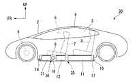
図1に示すように、車両1は、フロントウインドガラス2、左右サイドウインドガラス3及びルーフ4等によって囲まれた客室5を有している。車両1は、フロアパネル6上で客室5内に、乗員が着座する前席7及び後席8を有している。<First Embodiment>
As shown in FIG. 1, the
車両1は、EV(Electric Vehicle:電気自動車)であって、駆動用のモータ(駆動部)9及びバッテリ(第1蓄電部11及び第2蓄電部12)を備えている。モータ9は、第1蓄電部11及び第2蓄電部12の少なくとも一方の電力で駆動する。モータ9は、車体前部のエンジンルーム内に搭載されたACモータ又はDCモータの他、インホイールモータであってもよい。車両1は、バッテリのみのエネルギーでモータ9を駆動するバッテリ式電気自動車の他、エンジン(内燃機関)を駆動用に併用するあるいは発電機として使用するハイブリッド自動車、及び燃料電池で発電する燃料電池自動車であってもよい。 The
車両1は、客室5の外部であってフロアパネル6の下面に(換言すれば、客室5の外部かつ客室5の鉛直方向下方に)、バッテリユニット10を配置している。バッテリユニット10は、互いに充電容量の異なる第1蓄電部11及び第2蓄電部12を備えている。 The
第1蓄電部(ES−E)11は高容量型電池であり、第2蓄電部(ES−P)12は高出力型電池である。第2蓄電部12は、第1蓄電部11と比べて、エネルギー重量密度が劣り、出力重量密度が優れるバッテリである。第1蓄電部11は、第2蓄電部12よりも大きなエネルギー容量を有している。第1蓄電部11は、走行距離を確保するために第2蓄電部12よりも大きなサイズとすることが好ましい。第1蓄電部11は、後席8の左右全幅に渡って後席8の鉛直方向下方に配置されている。第1蓄電部11は、複数の電池ブロックの積み重ねにより、後部よりも前部の高さを増して形成されている。第1蓄電部11は、第2蓄電部12よりも内部抵抗が大きく高温になりやすい。 The first power storage unit (ES-E) 11 is a high-capacity battery, and the second power storage unit (ES-P) 12 is a high-power battery. The second
第2蓄電部12は、第1蓄電部11よりも小型であるが、第1蓄電部11よりも大きな電流で充放電を行うことができる。第2蓄電部12は、前席7左側の鉛直方向下方に配置されている。すなわち、第2蓄電部12は、第1蓄電部11よりも車両前後方向の前方に配置されている。 The second
第1蓄電部11及び第2蓄電部12は、それぞれ不図示の複数の電池ブロックを直列に接続して構成されている。電池ブロックの数や各電池ブロックに含まれる単電池の数は、各蓄電部11,12の要求出力や容量などを考慮して適宜設定することができる。単電池としては、ニッケル水素電池やリチウムイオン電池といった二次電池を用いることができる。
このように特性の異なる2つの蓄電部11,12を備え、例えば第1蓄電部11がモータ9の要求電力に依存しない一定電力を放電し、第2蓄電部12が一定電力と要求電力の差分を充放電するような各蓄電部11,12の特性を利用した制御を行うことで、2つの蓄電部11,12を単一の蓄電部では達成困難な高いエネルギー密度とパワー密度を兼ね備えた理想的な蓄電部として扱うことが可能になる。このような理想的な蓄電部は、高容量型又は高出力型のいずれか一方の蓄電部のみを備えた場合と比べて、重量や体積、更にはコストの面でも優位である。The first
Thus, the two
図1〜図4を参照し、バッテリユニット10は、第1蓄電部11及び第2蓄電部12の他、電力変換部13と、接続部14と、支持体15と、ファン16と、筐体17と、を備えている。 1 to 4, the
電力変換部13は、第1蓄電部11及び第2蓄電部12の少なくとも一方と車両1の外部の電力系統との間で電力変換を行う。電力変換部13は、前席7右側の鉛直方向下方に配置され、第2蓄電部12の右側に隣接している。すなわち、電力変換部13は、車両左右方向において第1蓄電部11と重なるよう配置されている。 The
接続部14は充電コネクタであり、車両左右方向における電力変換部13と同側(右側)に設けられ、車両右側面にリッド等を介して露出可能である。すなわち、接続部14は、左右の車両側面のうち、電力変換部13に近い方に設けられている。接続部14は、電力変換部13に隣接して設けられたり一体に設けられてもよい。 The
支持体15は、筐体17におけるバッテリユニット10の各機器を一体的に搭載するベース板である。支持体15上には、第1蓄電部11、第2蓄電部12及び電力変換部13の他、モータ9に接続されるインバータ、第1蓄電部11及び電力変換部13とインバータとの間に介設される昇圧コンバータ、第2蓄電部12とインバータとの間に介設される昇圧コンバータ、各種のコントローラ及びジャンクションボックスが支持されている(何れも不図示)。 The
筐体17は、例えば樹脂又は金属製の箱形状に形成され、客室5の外部でフロアパネル6の下方に配置可能な高さ寸法の偏平状に形成されている。筐体17は、支持体15に筐体上物を被せて固定することで箱形状に形成されている。筐体17は、客室5の外部で車両前方側に開口する外気導入口18と、客室5の外部で車両後方側に開口する外気導出口19と、を有している。これら外気導入口18及び外気導出口19とファン16並びに筐体17により、筐体17内に第1蓄電部11及び第2蓄電部12を冷却する単一の冷却回路20が形成されている。 The
バッテリユニット10をフロアパネル6の下面に取り付けたとき、筐体17内には、車両前後方向の前側から後側に向けて、ファン16、第2蓄電部12および電力変換部13、並びに第1蓄電部11の順にこれらが収容されている。すなわち、第1蓄電部11及び第2蓄電部12は、客室5の外部かつ客室5の鉛直方向下方に配置されており、第2蓄電部12は、第1蓄電部11より車両前後方向の前方に配置されている。 When the
筐体17内には、外気導入口18から走行風が導入可能であり、この走行風が第2蓄電部12、第1蓄電部11の順にこれらを冷却した後、外気導出口19から後方へ排気される。筐体17内には、車両1の停止状態であっても、ファン16の駆動により外気導入口18から外気が導入され、この外気が第2蓄電部12、第1蓄電部11の順にこれらを冷却した後、外気導出口19から後方へ排気される。ファン16は電動ファンであり、例えば第1蓄電部11及び第2蓄電部12の少なくとも一方の電力で駆動する。図1の例では、ファン16が外気導入口18の近傍に配置され、外気導入口18より直接的に外気を吸引して筐体17内に導入する。なお、ファン16が外気導出口19の近傍に配置され、筐体17内に負圧を発生させて外気導入口18より外気を導入する構成でもよい。 A running wind can be introduced into the
バッテリユニット10は、支持体15上に、第1蓄電部11、第2蓄電部12、電力変換部13及びファン16等を搭載して一体的に支持し、その後に支持体15に筐体上物を被せて箱形状の筐体17を形成することで、筐体17内に各機器を収容した一体のユニットとなる。バッテリユニット10は、車両1に取り付けられた状態で、第2蓄電部12を第1蓄電部11より車両前方に配置する。 The
バッテリユニット10は、車両1の下方から客室5の外部かつ鉛直下方に取り付けられている。これにより、駆動用バッテリ(各蓄電部11,12)及びそれに係る各機器の車両1への取り付けが容易になる。各蓄電部11,12を客室5の外部かつ鉛直下方に取り付けることは、車室内空間への影響を抑え、かつ車両1の重心を下げる点でも好ましい。 The
バッテリユニット10は、比較的発熱量の少ない第2蓄電部12を比較的発熱量の多い第1蓄電部11よりも冷却回路20の上流側に配置しているので、各蓄電部11,12を冷媒(外気)で効率よく冷却可能である。バッテリユニット10は、第2蓄電部12を第1蓄電部11よりも車両前方に配置しているので、筐体17内に走行風を導入すれば、各蓄電部11,12を走行風で効率よく冷却可能である。すなわち、第1蓄電部11と第2蓄電部12の冷却上の上限温度は同程度であり、発熱量の少ない第2蓄電部12の冷却後の走行風でも十分に第1蓄電部11の冷却が可能である。しかし、第1蓄電部11と第2蓄電部12の順序を変えた場合には、この効果は得られない。 In the
以上説明したように、本実施形態によれば、第1蓄電部11及び第2蓄電部12の双方が、客室5の外部かつ客室5の鉛直方向下方に配置されているので、車室内空間を広く確保できるとともに、第1蓄電部11及び第2蓄電部12を一体的に取り付け可能とし、車体への組み付け工数を削減できる。
また、比較的小容積で済む高出力型バッテリである第2蓄電部12を客室前方側(前席7側)に配置しているので、前席7周りの空間を広く確保できるとともに、比較的大容積の高容量型バッテリである第1蓄電部11を客室後方側(後席8側)に配置しているので、荷室空間も併せて高容量型バッテリの配置空間を広く確保できる。
また、第1蓄電部11及び第2蓄電部12に個別の冷却回路を不要にできるため、システムの小型化と軽量化が図られるとともに、第2蓄電部12を第1蓄電部11より前方に配置しているので、第1蓄電部11及び第2蓄電部12を走行風で冷却する場合にも、発熱量の少ない第2蓄電部12を冷やした後の走行風で発熱量の多い第1蓄電部11を冷却できる。As described above, according to the present embodiment, both the first
In addition, since the second
In addition, since separate cooling circuits can be eliminated for the first
また、本実施形態によれば、第1蓄電部11及び第2蓄電部12が同一の筐体17内に収容されているので、第1蓄電部11及び第2蓄電部12の車体への組み付け工数を大幅に削減できる。また、筐体17内に冷媒を流すことで、第1蓄電部11及び第2蓄電部12の冷却を容易にできる。 Moreover, according to this embodiment, since the 1st
また、本実施形態によれば、冷却回路20が第2蓄電部12、第1蓄電部11の順に冷却するので、内部抵抗が小さく発熱量が少ない第2蓄電部12を先に冷やした後、内部抵抗が大きく発熱量の多い第2蓄電部12を冷やすので、第1蓄電部11及び第2蓄電部12を効率的に冷却できる。 Further, according to the present embodiment, since the
また、本実施形態によれば、比較的小さい第2蓄電部12が前席7の鉛直方向下方に配置され、比較的大きい第1蓄電部11が後席8の鉛直方向上方に配置されているので、蓄電容量を確保しつつ使用頻度の高い前席7の空間を広く確保できる。 Further, according to the present embodiment, the relatively small second
また、本実施形態によれば、第1蓄電部11及び第2蓄電部12と外部の電力系統との間で電力変換を行う電力変換部13を、車両左右方向において第1蓄電部11と重なるよう配置しているので、電力変換部13を第1蓄電部11及び第2蓄電部12とともに床下に配置可能となり、積載容量を増やすとともに、電力変換部13を車載しない場合や荷室に別体として搭載した場合と比べて、外部給電の際の手間を大幅に削減できる。 Further, according to the present embodiment, the
また、本実施形態によれば、第1蓄電部11、第2蓄電部12及び電力変換部13が同一の筐体17内に収容されているので、第1蓄電部11、第2蓄電部12及び電力変換部13の組み付け工数を大幅に削減できる。 Moreover, according to this embodiment, since the 1st
また、本実施形態によれば、電力変換部13と外部電力系統との電気的接点である接続部14が、左右の車両側面のうち、電力変換部13に近い方に設けられているので、電力変換部13及び接続部14を近接して配置でき、配線の省線化を図ることができる。 Moreover, according to this embodiment, since the
<第2実施形態>
次に、本発明の第2実施形態について図5を参照して説明する。
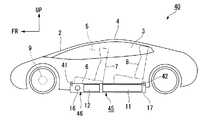
この実施形態の車両30及びバッテリユニット35は、前記第1実施形態に対して、外気導入口18にエバポレータ31を配置した点で特に異なる。その他の、前記実施形態と同一構成には同一符号を付して詳細説明は省略する。Second Embodiment
Next, a second embodiment of the present invention will be described with reference to FIG.
The
エバポレータ31は、例えば車両30のエアコン冷媒を用いて空気を冷やす熱交換器であり、筐体17内で外気導入口18の後方(下流側)に近接して配置され、かつ各蓄電部11,12の前方(上流側)に配置されている。図5の例では、エバポレータ31と各蓄電部11,12との間にファン16が配置されている。外気導入口18、外気導出口19、ファン16、エバポレータ31及び筐体17により、筐体17内に第1蓄電部11及び第2蓄電部12を冷却する単一の冷却回路36が形成されている。これにより、外気導入口18から筐体17内に導入される外気がエバポレータ31により冷却され、下流側の各蓄電部11,12が良好に冷却される。 The evaporator 31 is a heat exchanger that cools air using, for example, an air conditioner refrigerant of the
<第3実施形態>
次に、本発明の第3実施形態について図6を参照して説明する。
この実施形態の車両40及びバッテリユニット45は、前記第1実施形態に対して、外気導入口18及び外気導出口19に代わり、客室5内に開口する室内気導入口41及び室内気導出口42を筐体17に有する点で特に異なる。その他の、前記実施形態と同一構成には同一符号を付して詳細説明は省略する。<Third Embodiment>
Next, a third embodiment of the present invention will be described with reference to FIG.
The
筐体17内には、室内気導入口41から客室5内の空気が導入可能であり、この空気が第2蓄電部12、第1蓄電部11の順にこれらを冷却した後、室内気導出口42から客室5内に排気される。室内気導入口41、室内気導出口42、ファン16及び筐体17により、筐体17内に第1蓄電部11及び第2蓄電部12を冷却する単一の冷却回路46が形成されている。客室5内の空気は外気と比べて温度が安定しており、各蓄電部11,12の冷却性能を維持しやすい構成となる。 Air in the
<第4実施形態>
次に、本発明の第4実施形態について図7を参照して説明する。
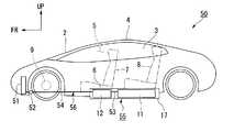
この実施形態の車両50及びバッテリユニット55は、前記各実施形態に対して、各蓄電部11,12を水冷とした点で特に異なる。その他の、前記実施形態と同一構成には同一符号を付して詳細説明は省略する。<Fourth embodiment>
Next, a fourth embodiment of the present invention will be described with reference to FIG.
The
車両50は、筐体17内に各蓄電部11,12等を冷却可能に設けられた冷媒流路53と、車両50の例えば前端部に設けられたラジエータ51と、ラジエータ51及び冷媒流路53の間に渡って延びる接続流路54と、ラジエータ51及び冷媒流路53の間で冷却水を循環させる電動のウォータポンプ52と、を備えている。筐体17、冷媒流路53、ラジエータ51、接続流路54及びウォータポンプ52により、筐体17内に第1蓄電部11及び第2蓄電部12を冷却する単一の冷却回路56が形成されている。これにより、各蓄電部11,12を空冷とする前記実施形態よりも各蓄電部11,12の冷却性能を向上させやすい。 The
<第5実施形態>
次に、本発明の第5実施形態について図8を参照して説明する。
この実施形態の車両60及びバッテリユニット65は、前記第4実施形態の車両50に対して、冷却水を冷却するチラー61を配置した点で特に異なる。その他の、前記実施形態と同一構成には同一符号を付して詳細説明は省略する。<Fifth Embodiment>
Next, a fifth embodiment of the present invention will be described with reference to FIG.
The
チラー61は、例えば車両60のエアコン冷媒を用いて冷却水を冷やす熱交換器であり、例えば接続流路54でウォータポンプ52と筐体17との間に配置されている。チラー61は、ラジエータ51から筐体17内の冷媒流路53に導入する冷却水を冷却し、下流側の各蓄電部11,12を良好に冷却可能とする。筐体17、冷媒流路53、ラジエータ51、接続流路54、チラー61及びウォータポンプ52により、筐体17内に第1蓄電部11及び第2蓄電部12を冷却する単一の冷却回路66が形成されている。これにより、前記第4実施形態よりも各蓄電部11,12の冷却性能を向上させる。 The
なお、本発明は上記各実施形態に限られるものではなく、その要旨を逸脱しない範囲で種々の設計変更が可能である。例えば、図6の例でも図5と同様にエバポレータ31を配置してもよい。チラー61は各蓄電部11,12より上流側であれば筐体17内に配置してもよく、かつ各蓄電部11,12と位置が重なってもよい。
客室5に配置される座席は前席7及び後席8に限定されず、後席8を前後2列にした3列シートであってもよい。筐体17に形成される外気導入口18は、車両下面を覆うアンダーカバー等に一体成型されてもよい。
そして、上記各実施形態における構成は本発明の一例であり、発明の要旨を逸脱しない範囲で種々の変更が可能である。The present invention is not limited to the above embodiments, and various design changes can be made without departing from the scope of the invention. For example, the evaporator 31 may be disposed in the example of FIG. 6 as in FIG. The
The seats arranged in the
The configurations in the above embodiments are examples of the present invention, and various modifications can be made without departing from the scope of the invention.
1,30,40,50,60 車両
5 客室
7 前席
8 後席
9 モータ(駆動部)
10,35,45,55,65 バッテリユニット
11 第1蓄電部
12 第2蓄電部
13 電力変換部
14 接続部
15 支持体
17 筐体
20,36,46,56,66 冷却回路1, 30, 40, 50, 60
10, 35, 45, 55, 65
Claims (9)
Translated fromJapanese前記第1蓄電部と比して出力重量密度が優れる第2蓄電部と、
前記第1蓄電部の電力及び前記第2蓄電部の電力の少なくとも一方で駆動する駆動部と、を含み、
前記第1蓄電部及び前記第2蓄電部は、客室の外部かつ前記客室の鉛直方向下方に配置され、
前記第2蓄電部は、前記第1蓄電部より車両前後方向の前方に配置されている、車両。A first power storage unit;
A second power storage unit having an output weight density superior to that of the first power storage unit;
A drive unit that drives at least one of the power of the first power storage unit and the power of the second power storage unit,
The first power storage unit and the second power storage unit are disposed outside a guest room and vertically below the guest room,
The second power storage unit is a vehicle disposed in front of the first power storage unit in the vehicle front-rear direction.
前記第1蓄電部の内部抵抗は、前記第2蓄電部の内部抵抗より大きく、
前記冷却回路は、前記第2蓄電部、前記第1蓄電部の順にこれらを冷却する、請求項1又は2に記載の車両。A single cooling circuit for cooling the first power storage unit and the second power storage unit;
The internal resistance of the first power storage unit is greater than the internal resistance of the second power storage unit,
The vehicle according to claim 1 or 2, wherein the cooling circuit cools the second power storage unit and the first power storage unit in this order.
前記第1蓄電部の体積は、前記第2蓄電部の体積より大きく、
前記第2蓄電部は、前記前席の鉛直方向下方に配置され、
前記第1蓄電部は、前記後席の鉛直方向下方に配置されている、請求項1から3の何れか一項に記載の車両。Including a front seat and a rear seat provided in the cabin;
The volume of the first power storage unit is larger than the volume of the second power storage unit,
The second power storage unit is disposed vertically below the front seat,
The vehicle according to any one of claims 1 to 3, wherein the first power storage unit is disposed vertically below the rear seat.
前記電力変換部は、車両左右方向において前記第1蓄電部と重なるよう配置されている、請求項1から4の何れか一項に記載の車両。A power conversion unit that performs power conversion between at least one of the first power storage unit and the second power storage unit and a power system outside the vehicle;
The vehicle according to any one of claims 1 to 4, wherein the power conversion unit is arranged to overlap the first power storage unit in a vehicle left-right direction.
前記接続部は、左右の車両側面のうち、前記電力変換部に近い方に設けられている、請求項5又は6に記載の車両。Including a connection part that is an electrical contact between the power conversion part and the power system;
The said connection part is a vehicle of Claim 5 or 6 provided in the direction near the said electric power conversion part among the vehicle side surfaces on either side.
前記第1蓄電部と比して出力重量密度が優れる第2蓄電部と、
車両の客室の外部かつ前記客室の鉛直方向下方に配置可能であり、前記第2蓄電部を、前記第1蓄電部より車両前後方向の前方に配置した状態で、前記第1蓄電部及び前記第2蓄電部を一体的に支持可能な支持体と、を含む、バッテリユニット。A first power storage unit;
A second power storage unit having an output weight density superior to that of the first power storage unit;
The first power storage unit and the second power storage unit can be disposed outside the passenger compartment of the vehicle and vertically below the guest room, and the second power storage unit is disposed in front of the first power storage unit in the vehicle front-rear direction. 2 A battery unit including a support that can integrally support the power storage unit.
Priority Applications (3)
| Application Number | Priority Date | Filing Date | Title |
|---|---|---|---|
| JP2016051500AJP2017165222A (en) | 2016-03-15 | 2016-03-15 | Vehicle, battery unit, and battery mounting method for vehicle |
| US15/447,133US20170267120A1 (en) | 2016-03-15 | 2017-03-02 | Vehicle, battery unit and battery carrying method of vehicle |
| CN201710148240.XACN107195985A (en) | 2016-03-15 | 2017-03-13 | The battery-mounting method of vehicle, battery unit and vehicle |
Applications Claiming Priority (1)
| Application Number | Priority Date | Filing Date | Title |
|---|---|---|---|
| JP2016051500AJP2017165222A (en) | 2016-03-15 | 2016-03-15 | Vehicle, battery unit, and battery mounting method for vehicle |
Publications (1)
| Publication Number | Publication Date |
|---|---|
| JP2017165222Atrue JP2017165222A (en) | 2017-09-21 |
Family
ID=59847489
Family Applications (1)
| Application Number | Title | Priority Date | Filing Date |
|---|---|---|---|
| JP2016051500APendingJP2017165222A (en) | 2016-03-15 | 2016-03-15 | Vehicle, battery unit, and battery mounting method for vehicle |
Country Status (3)
| Country | Link |
|---|---|
| US (1) | US20170267120A1 (en) |
| JP (1) | JP2017165222A (en) |
| CN (1) | CN107195985A (en) |
Families Citing this family (5)
| Publication number | Priority date | Publication date | Assignee | Title |
|---|---|---|---|---|
| JP6348929B2 (en)* | 2016-05-23 | 2018-06-27 | 本田技研工業株式会社 | Power system, transport equipment, and power transmission method |
| JP6465082B2 (en)* | 2016-07-29 | 2019-02-06 | トヨタ自動車株式会社 | Vehicle structure |
| US11007900B2 (en)* | 2018-09-07 | 2021-05-18 | Ford Global Technologies, Llc | Battery thermal management assembly and method |
| JP7605672B2 (en)* | 2021-03-19 | 2024-12-24 | 本田技研工業株式会社 | Power System |
| CN115366647B (en)* | 2022-09-07 | 2024-08-09 | 中国重汽集团济南动力有限公司 | Power system for electric heavy truck |
Citations (11)
| Publication number | Priority date | Publication date | Assignee | Title |
|---|---|---|---|---|
| JP2006079987A (en)* | 2004-09-10 | 2006-03-23 | Nissan Motor Co Ltd | Hybrid battery system |
| JP2007311290A (en)* | 2006-05-22 | 2007-11-29 | Toyota Motor Corp | Power supply |
| JP2009126452A (en)* | 2007-11-27 | 2009-06-11 | Honda Motor Co Ltd | Vehicle equipped with a fuel cell power system |
| JP2013035323A (en)* | 2011-08-04 | 2013-02-21 | Kojima Press Industry Co Ltd | Cooling structure of vehicular power supply device |
| US20130206491A1 (en)* | 2010-07-12 | 2013-08-15 | Kor Ecologoic Inc. | Vehicle |
| WO2014069270A1 (en)* | 2012-11-05 | 2014-05-08 | 日産自動車株式会社 | Battery temperature regulation device |
| JP2014184862A (en)* | 2013-03-25 | 2014-10-02 | Toyota Motor Corp | Cooling system of electric vehicle |
| JP2015093517A (en)* | 2013-11-08 | 2015-05-18 | 日産自動車株式会社 | Battery temperature control device |
| JP2015107728A (en)* | 2013-12-04 | 2015-06-11 | 本田技研工業株式会社 | Electric vehicle |
| JP2015216070A (en)* | 2014-05-13 | 2015-12-03 | 三菱自動車工業株式会社 | Battery pack |
| JP2016215947A (en)* | 2015-05-25 | 2016-12-22 | トヨタ自動車株式会社 | Electric vehicle |
Family Cites Families (2)
| Publication number | Priority date | Publication date | Assignee | Title |
|---|---|---|---|---|
| JP4319239B2 (en)* | 2008-02-07 | 2009-08-26 | 本田技研工業株式会社 | Hybrid vehicle |
| EP2402191B1 (en)* | 2009-02-24 | 2016-09-28 | Nissan Motor Co., Ltd. | Battery installation structure |
- 2016
- 2016-03-15JPJP2016051500Apatent/JP2017165222A/enactivePending
- 2017
- 2017-03-02USUS15/447,133patent/US20170267120A1/ennot_activeAbandoned
- 2017-03-13CNCN201710148240.XApatent/CN107195985A/enactivePending
Patent Citations (11)
| Publication number | Priority date | Publication date | Assignee | Title |
|---|---|---|---|---|
| JP2006079987A (en)* | 2004-09-10 | 2006-03-23 | Nissan Motor Co Ltd | Hybrid battery system |
| JP2007311290A (en)* | 2006-05-22 | 2007-11-29 | Toyota Motor Corp | Power supply |
| JP2009126452A (en)* | 2007-11-27 | 2009-06-11 | Honda Motor Co Ltd | Vehicle equipped with a fuel cell power system |
| US20130206491A1 (en)* | 2010-07-12 | 2013-08-15 | Kor Ecologoic Inc. | Vehicle |
| JP2013035323A (en)* | 2011-08-04 | 2013-02-21 | Kojima Press Industry Co Ltd | Cooling structure of vehicular power supply device |
| WO2014069270A1 (en)* | 2012-11-05 | 2014-05-08 | 日産自動車株式会社 | Battery temperature regulation device |
| JP2014184862A (en)* | 2013-03-25 | 2014-10-02 | Toyota Motor Corp | Cooling system of electric vehicle |
| JP2015093517A (en)* | 2013-11-08 | 2015-05-18 | 日産自動車株式会社 | Battery temperature control device |
| JP2015107728A (en)* | 2013-12-04 | 2015-06-11 | 本田技研工業株式会社 | Electric vehicle |
| JP2015216070A (en)* | 2014-05-13 | 2015-12-03 | 三菱自動車工業株式会社 | Battery pack |
| JP2016215947A (en)* | 2015-05-25 | 2016-12-22 | トヨタ自動車株式会社 | Electric vehicle |
Also Published As
| Publication number | Publication date |
|---|---|
| CN107195985A (en) | 2017-09-22 |
| US20170267120A1 (en) | 2017-09-21 |
Similar Documents
| Publication | Publication Date | Title |
|---|---|---|
| US10343548B2 (en) | Onboard battery for vehicle | |
| CN204845501U (en) | Electronic vehicle group battery of sectional type chassis installation | |
| JP6622368B2 (en) | Automotive battery | |
| CN104756305B (en) | Battery temperature control device | |
| KR101017087B1 (en) | Power supply pack mounting structure | |
| US7511455B2 (en) | Power supply unit having uniform battery characteristic | |
| CN104126246B (en) | The accumulator battery temperature regulating structure of electric automobile | |
| US9174520B2 (en) | Electric vehicle | |
| JP4576931B2 (en) | Electrical equipment mounting structure | |
| US9742043B2 (en) | Battery pack temperature control structure for electric vehicles | |
| JP6011949B2 (en) | Automotive battery | |
| JP4337905B2 (en) | Cooling device for electric equipment mounted on vehicle | |
| JP4917307B2 (en) | Battery pack | |
| CN108630852B (en) | High-voltage unit casing for vehicle, high-voltage unit and vehicle | |
| CN102239060A (en) | Power supply device mounting structure | |
| JP2017165222A (en) | Vehicle, battery unit, and battery mounting method for vehicle | |
| WO2015146387A1 (en) | Electrically driven vehicle | |
| JP2013107420A (en) | Cooling system for vehicular battery | |
| JP6122414B2 (en) | Electric vehicle | |
| JP5831343B2 (en) | Mounting structure of an inverter for external power feeding of a vehicle equipped with a power supply device | |
| JP6690588B2 (en) | Fuel cell vehicle | |
| JP6834744B2 (en) | Fuel cell unit | |
| JP4978050B2 (en) | Electricity storage pack | |
| JP2005205953A (en) | Cooling device for electrical equipment | |
| JP6855901B2 (en) | High voltage unit |
Legal Events
| Date | Code | Title | Description |
|---|---|---|---|
| A977 | Report on retrieval | Free format text:JAPANESE INTERMEDIATE CODE: A971007 Effective date:20171018 | |
| A131 | Notification of reasons for refusal | Free format text:JAPANESE INTERMEDIATE CODE: A131 Effective date:20171024 | |
| A521 | Request for written amendment filed | Free format text:JAPANESE INTERMEDIATE CODE: A523 Effective date:20171211 | |
| A131 | Notification of reasons for refusal | Free format text:JAPANESE INTERMEDIATE CODE: A131 Effective date:20180515 | |
| A02 | Decision of refusal | Free format text:JAPANESE INTERMEDIATE CODE: A02 Effective date:20181106 |