JP2017157433A - X-ray high voltage apparatus and X-ray CT apparatus - Google Patents
X-ray high voltage apparatus and X-ray CT apparatusDownload PDFInfo
- Publication number
- JP2017157433A JP2017157433AJP2016040086AJP2016040086AJP2017157433AJP 2017157433 AJP2017157433 AJP 2017157433AJP 2016040086 AJP2016040086 AJP 2016040086AJP 2016040086 AJP2016040086 AJP 2016040086AJP 2017157433 AJP2017157433 AJP 2017157433A
- Authority
- JP
- Japan
- Prior art keywords
- voltage
- ray
- target value
- output voltage
- exposure
- Prior art date
- Legal status (The legal status is an assumption and is not a legal conclusion. Google has not performed a legal analysis and makes no representation as to the accuracy of the status listed.)
- Pending
Links
Images


Landscapes
- X-Ray Techniques (AREA)
Abstract
Description
Translated fromJapanese本願発明は、X線高電圧装置、特に、負荷の急激な変動に起因する直流変換回路における電圧の跳ね上がりを抑制するX線高電圧装置に関する。 The present invention relates to an X-ray high-voltage device, and more particularly to an X-ray high-voltage device that suppresses a voltage jump in a DC conversion circuit caused by a rapid load change.
X線CT装置やX線撮影装置等に適用されるX線高電圧装置では、系統からの交流電圧を直流電圧に変換するための直流変換装置を備えている。直流変換装置には、主として三相コンバータ回路や昇圧チョッパ回路等の回路が適用されており、これらの回路はいずれもDCバスコンデンサと絶縁ゲートバイポーラトランジスタ(IGBT)モジュールとを備えている。直流変換装置では、系統から供給された交流電圧を直流に変換し、一旦DCバスコンデンサに蓄積して、インバータや負荷等に供給している。出力電圧としてのDCバスコンデンサ電圧は一定の値に保つように制御されている。 An X-ray high voltage apparatus applied to an X-ray CT apparatus, an X-ray imaging apparatus or the like includes a DC converter for converting an AC voltage from a system into a DC voltage. Circuits such as a three-phase converter circuit and a step-up chopper circuit are mainly applied to the DC converter, and each of these circuits includes a DC bus capacitor and an insulated gate bipolar transistor (IGBT) module. In the DC converter, the AC voltage supplied from the system is converted to DC, temporarily stored in a DC bus capacitor, and supplied to an inverter, a load, or the like. The DC bus capacitor voltage as the output voltage is controlled to be maintained at a constant value.
ところで、例えばX線CT装置では、撮影の開始時にはX線管の出力は0kWから高出力に、撮影の終了時には高出力から0kWに瞬間的に変化する。X線CT装置にX線管の電力供給源としてX線高電圧装置が適用された場合、X線高電圧装置側からみると、撮影の開始時は軽負荷から重負荷に、撮影の終了時は重負荷から軽負荷に、いずれも負荷が瞬時に変化する。 By the way, in an X-ray CT apparatus, for example, the output of the X-ray tube instantaneously changes from 0 kW to high output at the start of imaging and from high output to 0 kW at the end of imaging. When an X-ray high voltage apparatus is applied as an X-ray tube power supply source to the X-ray CT apparatus, from the X-ray high voltage apparatus side, from the light load to the heavy load at the start of imaging, and at the end of imaging The load changes instantaneously from heavy load to light load.
X線高電圧装置に対する負荷の変動は、直流変換回路で生成されるDCバスコンデンサ電圧に影響を及ぼす。つまり、DCバスコンデンサ電圧は、瞬間的に負荷が重くなる場合、系統の内部インピーダンスや昇圧用のインダクタによる電圧降下との関係で所望の電圧よりも数十V降下する。一方、瞬間的に負荷が軽くなる場合、DCバスコンデンサ電圧は所望の電圧よりも数十V跳ね上がる。このようなDCバスコンデンサ電圧の上昇(跳ね上がり)は、サージ電圧やSEB(Single Event Burnout)によってIGBTモジュールの故障を引き起こし、装置の信頼性が低下する虞があることから、DCバスコンデンサ電圧の下降及び上昇を抑制するX線高電圧装置が提案されている。 Load fluctuations for the X-ray high voltage device affect the DC bus capacitor voltage generated by the DC converter circuit. That is, the DC bus capacitor voltage drops several tens of volts below the desired voltage due to the internal impedance of the system and the voltage drop due to the boosting inductor when the load increases momentarily. On the other hand, when the load is lightened instantaneously, the DC bus capacitor voltage jumps several tens of volts from the desired voltage. Such an increase (bounce) of the DC bus capacitor voltage may cause a failure of the IGBT module due to a surge voltage or SEB (Single Event Burnout), and the reliability of the device may be lowered. And the X-ray high voltage apparatus which suppresses a raise is proposed.
例えば、特許文献1には、X線曝射開始時及び曝射終了時に合わせて、コンバータ回路1の出力電圧、つまり平滑コンデンサ9の電圧(以下、「コンデンサ電圧」という)を制御するための制御ゲインを切替えて、コンデンサ電圧の降下及び跳ね上がりを抑制するX線高電圧装置が開示されている。 For example,
具体的には、特許文献1のX線高電圧装置では、コンバータ制御回路により、出力電圧調節器及び入力電流調節器の制御ゲインを、コンバータ回路の出力電圧であるコンデンサ電圧の設定時(X線曝射準備時)及びX線曝射終了時とX線曝射時とで切り換え、双方に最適な制御ゲインを曝射条件に応じて自由に選択できるようにしている。そして、X線曝射時は、非曝射時と比較して制御ゲインを大きく設定することにより、負荷が重い場合でもコンデンサ電圧の落ち込みを小さく抑える。一方、X線曝射終了時は、再び無負荷状態となるので制御ゲインを小さくすることにより、曝射終了後のコンデンサ電圧のオーバーシュートを防止している。 Specifically, in the X-ray high voltage apparatus of
上述した特許文献1のX線高電圧装置は、コンデンサ電圧を検出し、検出したコンデンサ電圧と目標電圧との偏差から制御ゲインを算出して制御を行っている。つまり、負荷に変化が生じた場合に、コンデンサ電圧が上昇又は下降したことを検出し、その後、負荷の変動に追従して出力電圧が目標値となるように制御を行っている。このため、特許文献1のX線高電圧装置を、例えば、X線CT装置のように瞬間的に負荷が変動する装置に適用した場合は、負荷の瞬間的な変動にX線高電圧装置の制御が追い付かず、コンデンサ電圧の上昇又は下降を十分に抑制することができない。 The above-described X-ray high voltage apparatus of
特に、上述のようにバスコンデンサ電圧の上昇は、IGBTモジュールの故障を引き起こし、装置の信頼性が低下する虞があるため、コンデンサ電圧の上昇を十分に制御する必要がある。
また、装置の小型化の要請によりDCバスコンデンサを低容量化する場合や、装置の出力容量を増大させる場合には、X線曝射時のバスコンデンサ電圧の降下又は上昇の傾向はより顕著になる。さらに、外国等の、系統からの入力電圧が高い地域においてX線高電圧装置を使用する場合には、DCバスコンデンサ電圧の目標電圧を高く設定する必要がある。従って、DCバスコンデンサ電圧の上昇(跳ね上がり)を十分に抑制することが望まれている。In particular, as described above, an increase in the bus capacitor voltage causes a failure of the IGBT module and may reduce the reliability of the device. Therefore, it is necessary to sufficiently control the increase in the capacitor voltage.
In addition, when the capacity of the DC bus capacitor is reduced due to the demand for downsizing of the apparatus or when the output capacity of the apparatus is increased, the tendency of the decrease or increase of the bus capacitor voltage during X-ray exposure is more prominent. Become. Furthermore, when the X-ray high voltage apparatus is used in an area where the input voltage from the system is high, such as in a foreign country, it is necessary to set the target voltage of the DC bus capacitor voltage high. Therefore, it is desired to sufficiently suppress the rise (bounce) of the DC bus capacitor voltage.
本発明は上記実情に鑑みてなされたものであり、直流変換回路における電圧の上昇を確実に抑制して装置の信頼性を向上させることを目的とする。 The present invention has been made in view of the above circumstances, and an object thereof is to reliably suppress an increase in voltage in a DC conversion circuit and improve the reliability of the apparatus.
上記課題を解決するために、本発明は以下の手段を提供する。
本発明の一態様は、交流電源から供給される電圧を直流電圧に変換し、負荷としてのX線管を含む共振回路に直流の電力を出力する直流変換回路と、
前記直流変換回路の出力の目標値である電圧目標値を設定する電圧目標値設定部と、
前記電圧目標値に一致するように前記直流変換回路の出力電圧を制御する出力電圧制御部と、を備え、前記出力電圧制御部が、前記X線管の曝射条件の変動に同期して、電圧目標値を切り替えて前記直流変換回路の出力電圧を制御するX線高電圧装置を提供する。In order to solve the above problems, the present invention provides the following means.
One aspect of the present invention is a DC conversion circuit that converts a voltage supplied from an AC power source into a DC voltage and outputs DC power to a resonance circuit including an X-ray tube as a load;
A voltage target value setting unit for setting a voltage target value that is a target value of the output of the DC converter circuit;
An output voltage control unit that controls an output voltage of the DC conversion circuit so as to match the voltage target value, and the output voltage control unit is synchronized with a change in an exposure condition of the X-ray tube, Provided is an X-ray high voltage apparatus for switching a voltage target value to control an output voltage of the DC conversion circuit.
本発明によれば、直流変換回路における電圧の上昇を確実に抑制して装置の信頼性を向上させることができる。 ADVANTAGE OF THE INVENTION According to this invention, the raise of the voltage in a DC converter circuit can be suppressed reliably, and the reliability of an apparatus can be improved.
以下、本発明の一実施形態について、図面を参照して説明する。
本発明に係るX線高電圧装置は、交流電源から供給される電圧を直流電圧に変換し、負荷としてのX線管を含む共振回路に直流の電力を出力する直流変換回路と、直流変換回路が出力すべき電圧目標値を、直流変換回路の出力の目標値である電圧目標値を設定する電圧目標値設定部と、と、電圧目標値設定部による電圧目標値に一致するように直流変換回路の出力電圧を制御する出力電圧制御部と、を備え、出力電圧制御部が、X線管の曝射条件の変動に同期して、電圧目標値を切り替えて前記直流変換回路の出力電圧を制御する。
本発明によれば、X線の曝射条件に応じて、直流変換回路の出力電圧に対する電圧目標値を設定している。ここで、X線の曝射条件には、X線高電圧装置が適用されるX線CT装置やX線撮影装置などの撮像装置における撮影条件に基づく曝射条件の他、X線曝射動作のオン/オフも含まれる。Hereinafter, an embodiment of the present invention will be described with reference to the drawings.
An X-ray high voltage apparatus according to the present invention converts a voltage supplied from an AC power source into a DC voltage, and outputs DC power to a resonance circuit including an X-ray tube as a load, and a DC conversion circuit The voltage target value to be output by the DC converter circuit is set to match the voltage target value set by the voltage target value setting unit for setting the voltage target value, which is the target value of the output of the DC converter circuit, and the voltage target value by the voltage target value setting unit. An output voltage control unit that controls the output voltage of the circuit, and the output voltage control unit switches the voltage target value in synchronization with fluctuations in the exposure conditions of the X-ray tube and outputs the output voltage of the DC conversion circuit. Control.
According to the present invention, the voltage target value for the output voltage of the DC conversion circuit is set according to the X-ray exposure conditions. Here, X-ray exposure conditions include X-ray exposure operations in addition to exposure conditions based on imaging conditions in an imaging apparatus such as an X-ray CT apparatus or an X-ray imaging apparatus to which the X-ray high voltage apparatus is applied. ON / OFF of this is included.
例えば、X線曝射のオンオフによっても電圧目標値を切り替えるので、X線の曝射が終了し、負荷としてのX線管への電力供給が不要となり実質的に軽負荷ないしは無負荷となった場合でも、これに応じた電圧目標値を設定してこれに切り替えることで、直流変換部における電圧の跳ね上がりを抑制することができる。 For example, since the voltage target value is switched by turning on / off the X-ray exposure, the X-ray exposure is completed, and the power supply to the X-ray tube as a load is not required, and the load becomes substantially light or no load. Even in this case, by setting a voltage target value corresponding to this and switching to it, it is possible to suppress a jump in voltage in the DC converter.
出力電圧制御部が、X線管の曝射の有無を判定する判定回路を備え、判定回路によりX線の曝射が終了したと判定された場合に、X線曝射時よりも低電圧の電圧目標値に切り替えて直流変換回路の出力電圧を制御するようにしてもよい。
また、電圧目標値設定部が、X線管の陽極駆動信号に基づいて電圧目標値を設定するようにしてもよい。The output voltage control unit includes a determination circuit that determines whether or not the X-ray tube has been exposed. When the determination circuit determines that the X-ray exposure has ended, the output voltage control unit has a lower voltage than that during X-ray exposure. The output voltage of the DC conversion circuit may be controlled by switching to the voltage target value.
The voltage target value setting unit may set the voltage target value based on the anode drive signal of the X-ray tube.
電圧目標値設定部が、X線管の曝射条件に対応させて予め定めた電圧目標値テーブルを保持し、電圧目標値テーブルからX線管の曝射条件に従って電圧目標値を設定してもよい。
出力電圧制御部が、エラー信号を受信した場合にX線曝射時よりも低電圧の電圧目標値に切り替えて直流変換回路の出力電圧を制御することもできる。
なお、エラー信号とは、X線高電圧装置の故障や、X線高電圧装置が適用された撮像装置において故障等が生じた場合に、X線高電圧装置の全体を制御する制御部から入力される信号である。The voltage target value setting unit holds a predetermined voltage target value table corresponding to the X-ray tube exposure conditions, and sets the voltage target value according to the X-ray tube exposure conditions from the voltage target value table. Good.
When the output voltage control unit receives an error signal, the output voltage of the DC conversion circuit can be controlled by switching to a voltage target value that is lower than that during X-ray exposure.
The error signal is input from a control unit that controls the entire X-ray high-voltage device when a failure of the X-ray high-voltage device or a failure occurs in an imaging device to which the X-ray high-voltage device is applied. Signal.
さらに、被検体の心拍に同期した管電流を生成するための管電流指令信号を生成する管電流指令生成部を備え、出力電圧制御部が、管電流指令信号に基づいて、X線管へ供給される管電流が高管電流から低管電流に切り替わるタイミングに同期させて、低管電流時に高管電流時よりも低電圧となるように電圧目標値を切り替えて前記直流変換回路の出力電圧を制御することもできる。 Furthermore, a tube current command generation unit for generating a tube current command signal for generating a tube current synchronized with the heartbeat of the subject is provided, and the output voltage control unit supplies the X-ray tube based on the tube current command signal. In synchronization with the timing when the tube current is switched from the high tube current to the low tube current, the voltage target value is switched so that the voltage at the low tube current is lower than that at the high tube current, and the output voltage of the DC converter circuit is changed. It can also be controlled.
以下、より具体的に本発明の実施形態について説明する。
<第1の実施形態>
以下、第1の実施形態に係るX線高電圧装置について図面を参照して説明する。本実施形態に係るX線高電圧装置は、例えば、X線撮影装置やX線CT装置等、X線を曝射することにより被写体の画像を取得する撮像装置に適用され、当撮像該装置における撮影条件によって、負荷であるX線管に供給すべき電力が変化する。Hereinafter, embodiments of the present invention will be described more specifically.
<First Embodiment>
The X-ray high voltage apparatus according to the first embodiment will be described below with reference to the drawings. The X-ray high-voltage apparatus according to the present embodiment is applied to an imaging apparatus that acquires an image of a subject by exposing X-rays, such as an X-ray imaging apparatus or an X-ray CT apparatus, for example. The power to be supplied to the X-ray tube as a load varies depending on the imaging conditions.
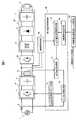
図1に示すように、X線高電圧装置は、直流変換部51、インバータ部52、高電圧発生部53、陽極駆動回路54、及び直流電圧制御回路55を備えている。また、高電圧発生部53には、負荷としてのX線管8が接続されている。 As shown in FIG. 1, the X-ray high voltage apparatus includes a
直流変換部51は、3相の交流電源1から供給される電圧を直流電圧に変換する直流変換回路2と、変換された直流電圧を一時的に蓄えるDCバスコンデンサ3とを備えている。直流変換部51は、後述する直流電圧制御回路55により制御され、直流電圧制御回路55の指示に従って、直流変換部51のDCバスコンデンサに蓄えらえた直流電圧はインバータ部52に供給される。
なお、直流変換部51には、例えば、三相電流制御型直流電圧変換装置や、全波整流回路及び昇圧チョッパ回路等を適用することができる。The
For example, a three-phase current control type DC voltage converter, a full-wave rectifier circuit, a boost chopper circuit, or the like can be applied to the
インバータ部52は、直流変換部51から供給された直流電圧を高周波交流電圧に変換する。 The
高電圧発生部53は、インバータ部52の出力電圧を高電圧に昇圧する高電圧変圧器5と、高電圧変圧器5の出力電圧を直流電圧に変換して昇圧するための全波多倍昇圧回路6と、全波多倍昇圧回路6の出力電圧を蓄える出力平滑コンデンサ7とを備えている。 The high
陽極駆動回路54は、X線管8の陽極が電子の衝突により溶融するのを防止するために陽極を回転させる。陽極駆動回路54は、直流変換部51の出力端に設けられ、DCバスコンデンサ3の出力電力により陽極を回転させるために用いる固定子コイル(図示せず)に電力を供給する。本実施形態においては、陽極駆動回路54により固定子コイルに供給される陽極駆動電圧を用いて、直流変換回路の出力電圧の目標値を定めることができる。このため、陽極駆動回路54から、陽極駆動電圧に係る電圧値を後述する出力電圧目標値設定部15に送信する。 The
直流電圧制御回路55は、直流変換部51の入力端に配置された電流検出回路9、入力電流制御部10、DCバスコンデンサ3の出力端に配置された出力電圧検出回路11、出力電圧制御部12、直流変換ドライブ回路13、X線曝射判定回路14、及び出力電圧目標値設定部15を備えている。 The DC
そして、直流電圧制御回路55にはX線高電圧装置動作トリガ回路56が接続されており、直流電圧制御回路55は、このX線高電圧装置動作トリガ回路56からの入力信号に従い、X線の曝射の有無に応じて動作する。
X線高電圧装置動作トリガ回路56は、図2に示すように、本実施形態に係るX線高電圧装置が適用されるX線CT装置等から送信されたX線の曝射のオンオフを示すX線曝射トリガ信号を受信し、このX線曝射トリガ信号に基づいて、X線高電圧装置を動作させるためのトリガ信号をX線曝射判定回路14に送信する。An X-ray high voltage device
As shown in FIG. 2, the X-ray high voltage apparatus
X線曝射判定回路14は、X線高電圧装置動作トリガ回路56から受信したトリガ信号に基づいて、本実施形態に係るX線高電圧装置が適用されるX線CT装置等におけるXの曝射の有無を判定し、判定結果に応じて、曝射有を示す「X線曝射信号」又は曝射無を示す「X線曝射停止信号」の何れかを出力電圧目標値設定部15に送信する。 Based on the trigger signal received from the X-ray high-voltage device
出力電圧目標値設定部15は、X線曝射判定回路14から入力された信号がX線曝射有を示すX線曝射信号である場合には、DCバスコンデンサ3の電圧が所定の電圧値となるように、例えば、750Vを電圧目標値として設定する。
また、出力電圧目標値設定部15は、X線曝射判定回路14から入力された信号がX線曝射無を示すX線曝射信号である場合には、X線曝射信号を受信した場合の電圧目標値より低い電圧値を電圧目標値として設定する。本実施形態においては、出力電圧目標値設定部15は、陽極駆動回路54から入力された陽極駆動電圧を用いて、DCバスコンデンサ3の電圧目標値を以下の数式(1)に基づいて設定する。When the signal input from the X-ray
The output voltage target

そして、上記(1)の結果を以下の条件に当てはめることにより、最終的な電圧目標値を設定する。なお、入力電源電圧は3相の交流電源1の出力電圧である。
(1)電圧目標基準値≦1.0の場合
電圧目標値は入力電源電圧ピーク値の1.1倍に設定する。
(2)電圧目標基準値>1.0の場合
電圧目標値は陽極駆動電圧の最小値に設定する。Then, the final voltage target value is set by applying the result of the above (1) to the following conditions. The input power supply voltage is the output voltage of the three-phase
(1) When voltage target reference value ≦ 1.0 The voltage target value is set to 1.1 times the input power supply voltage peak value.
(2) When the voltage target reference value> 1.0 The voltage target value is set to the minimum value of the anode drive voltage.
出力電圧制御部12は、差分器19及びPI補償器23を備え、差分器19は、出力電圧目標値設定部15から受け取った電圧目標値に係る電圧信号と、出力電圧検出回路11が検出した電圧信号との差分値を算出する。差分器19により算出された差分値はPI補償器23に入力される。 The output
PI補償器23は、検出されたDCバスコンデンサ3の出力電圧が電圧目標値よりも大きければ、出力を低減し、DCバスコンデンサ3の出力電圧を低減させるように動作する。反対に、検出されたDCバスコンデンサ3の出力電圧が電圧目標値よりも小さければ、出力を増大させ、DCバスコンデンサ3の出力電圧を増加させるように動作する。PI補償器23の出力は、PI補償器23の発振等を考慮し、入力電流制御部11に出力される。 If the detected output voltage of the
入力電流制御部11は、上限・下限リミット回路111、U相PI補償器116、V相PI補償器117、W相PI補償器118、乗算器84,85,86、及び差分器87,88,89を備えている。 The input
乗算器84,85,86には、予め定めたU相、V相、W相の入力電流位相指令値112,113,114が夫々入力される。PI補償器23の出力は、U相、V相、W相の各PI補償器116,117,118の発振を防止するため、上限・下限リミット回路111に入力され、所定の範囲内の大きさに制限される。上限・下限リミット回路111の出力は、U相、V相、W相の入力電流位相指令値112,113,114と乗算される。これにより、直流変換回路2に入力されるU相、V相、W相の電流の大きさを示す指令値(交流波形)が生成される。 Predetermined U-phase, V-phase, and W-phase input current
この指令値は、電流検出回路9によって検出された直流変換回路2に流れる各相の電流値と、差分器87,88,89により比較される。差分器87,88,89の出力は、U相、V相、W相のPI補償器116,117,118に入力され、差分値が正(検出した入力電流が指令値よりも小さい値)である場合には、PI補償器116,117,118は、その出力を増加する。その反対である場合には、PI補償器116,117,118は、その出力を減少させる。PI補償器116,117,118の出力は、それぞれ、直流変換回路ドライブ回路13に出力される。 This command value is compared with the current value of each phase flowing through the
直流変換回路ドライブ回路13は、入力されたPI補償器116,117,118の出力に応じて、直流変換回路2の各半導体スイッチング素子への出力信号を制御する。これにより、PI補償器116,117,118の出力が増加している場合には直流変換回路2に流れる電流を増大させ、PI補償器116,117,118の出力が減少している場合には直流変換回路2に流れる電流を減少させる制御をU相、V相、W相毎に行う。 The DC conversion
以下、このように構成されたX線高電圧装置において、X線曝射の有無に応じた直流変換回路の電圧制御の流れを、図3のフローチャートに従って説明する。 Hereinafter, in the X-ray high voltage apparatus configured as described above, the flow of voltage control of the DC conversion circuit according to the presence or absence of X-ray exposure will be described with reference to the flowchart of FIG.
本実施形態に係るX線高電圧装置が駆動されると、先ずX線曝射判定回路14が駆動し、X線の曝射の有無について判定が開始される。すなわち、X線高電圧装置が適用されたX線CT装置の電源が投入されると、X線高電圧装置が駆動しX線曝射判定回路14においてX線曝射の有無の判定を開始する(ステップS1)。このとき、出力電圧目標値設定部15では、電圧目標値の初期値として、例えば、750Vが設定されている。 When the X-ray high-voltage apparatus according to the present embodiment is driven, the X-ray
ステップS2では、X線の曝射が開始され、X線曝射判定回路14がX線高電圧装置動作トリガ回路56から受信したトリガ信号に基づいてX線の曝射の有無を判定する。X線の曝射が開始されると、X線曝射判定回路14は曝射有を示すX線曝射信号を出力するので、出力電圧制御部12が出力電圧目標値設定部15により設定された電圧目標値の初期値である750Vを維持するようにDCバスコンデンサ3の電圧を制御する。
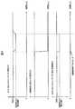
つまり、図4に示すように、X線曝射トリガ信号がオンである場合、すなわち、X線曝射判定回路14がX線高電圧装置動作トリガ回路56からX線曝射信号を受信している間は、DCバスコンデンサ3の電圧は750Vに維持されている。In step S2, X-ray exposure is started, and the X-ray
That is, as shown in FIG. 4, when the X-ray exposure trigger signal is on, that is, the X-ray
ステップS3では、X線曝射判定回路14は、X線曝射の終了を監視し、X線高電圧装置動作トリガ回路56からX線曝射無に係る信号を受信したか否か、つまり、X線曝射が終了したか否かを判定する。この判定は、X線曝射判定回路14が、X線高電圧装置動作トリガ回路56からX線曝射が停止されたことを示すトリガ信号を受信するまで継続する。X線曝射判定回路14では、X線曝射が停止されたことを示す信号を受信すると、X線曝射停止信号を電圧目標値設定部15に出力し、次のステップS4に進む。 In step S3, the X-ray
ステップS4では、出力電圧目標値設定部15が、X線曝射判定回路14からのX線曝射停止信号を受けて、電圧目標値を設定する。具体的には、上述した数式(1)に従って、電圧目標値を設定する。ここで設定される電圧目標値は、X線曝射信号を受信した場合の電圧目標値より低い電圧値であるので、DCバスコンデンサ3からみると、DCバスコンデンサ3の電圧は、電圧目標値よりも高い電圧値で制御されていることとなる。 In step S4, the output voltage target
図4に示すように、X線曝射判定回路14がX線高電圧装置動作トリガ回路56からX線曝射停止信号を受信すると、出力電圧目標値設定部15がX線曝射中の750Vよりも低い電圧値を示す電圧目標値に切り替え、切り替えられた電圧目標値に従って出力電圧制御部12がDCバスコンデンサ3の電圧を制御する。 As shown in FIG. 4, when the X-ray
出力電圧制御部12において、750Vよりも低い電圧値を示す電圧目標値とDCバスコンデンサとの差分値を算出すると、DCバスコンデンサ3の電圧値が電圧目標値よりも高いこととなる。従って、入力電流制御部10が、直流変換回路2に流れる電流を減少させるように制御する。これにより、DCバスコンデンサ3の電圧値は、電圧目標値に追従して徐々に低下するので、DCバスコンデンサ3における電圧の跳ね上がりを抑制することができる。 When the output
また、X線高電圧装置においては、出力電圧が所定の電圧で制御されていないとX線曝射の際に所望する時間で必要な管電圧及び管電流を得ることが出来なくなってしまう。このため、電圧目標値設定部15は、所定の時間(例えば、1秒)が経過した後、次のX線曝射に備えて電圧目標値を初期値に再度設定しなおす(ステップS5)。この電圧目標値を下げる所定の時間はX線高電圧装置を適用するアプリケーションにより異なる。 Further, in the X-ray high voltage apparatus, if the output voltage is not controlled at a predetermined voltage, it becomes impossible to obtain a necessary tube voltage and tube current in a desired time during X-ray exposure. For this reason, the voltage target
参考として、図5に電圧目標値を切り替えない場合の比較図を示す。直流変換部は,X線の曝射判定を行っていないため、負荷の変動を把握できない。このため,X線の曝射有無(負荷の変動)に対してDCバスコンデンサの電圧が変化したことを検出して、その後に、DCバスコンデンサ電圧が一定となるように制御する。従って、急激に無負荷又は軽負荷になってしまうと制御が追い付かず、DCバスコンデンサの電圧が跳ね上がってしまう。 For reference, FIG. 5 shows a comparison diagram when the voltage target value is not switched. Since the DC conversion unit does not perform the X-ray exposure determination, it cannot grasp the load fluctuation. For this reason, it is detected that the voltage of the DC bus capacitor has changed with respect to the presence or absence of X-ray exposure (load fluctuation), and thereafter, the DC bus capacitor voltage is controlled to be constant. Therefore, if the load suddenly becomes no load or light load, the control cannot catch up, and the voltage of the DC bus capacitor jumps up.
以上説明したように、本実施形態によれば、X線の曝射の有無を判定して、判定結果に応じて、直流変換回路の出力電圧に対する電圧目標値を設定している。すなわち、X線曝射のオン/オフを判定し、X線曝射がオフとなった際に直ちに電圧目標値を、X線曝射がオンの際の電圧目標値よりも低い電圧値に切り替える。 As described above, according to the present embodiment, the presence or absence of X-ray exposure is determined, and the voltage target value for the output voltage of the DC conversion circuit is set according to the determination result. That is, it is determined whether X-ray exposure is on / off, and immediately when the X-ray exposure is turned off, the voltage target value is switched to a voltage value lower than the voltage target value when the X-ray exposure is on. .
このため、X線の曝射が終了し、負荷としてのX線管への電力供給が不要となり実質的に軽負荷ないしは無負荷となった場合でも、直流変換部における電圧の跳ね上がりを抑制することができる。そして、直流変換部における電圧の跳ね上がりを抑制することで、直流変換部を構成するIGBTモジュール等の部品の損傷を防止することができ、X線高電圧装置の信頼性を向上させることができる。 For this reason, even when the X-ray exposure ends and no power supply to the X-ray tube as a load is required and the load becomes substantially light or no load, the jumping of the voltage in the DC conversion unit is suppressed. Can do. And by suppressing the jump of the voltage in a direct current | flow converter, damage to components, such as IGBT module which comprises a direct current | flow converter, can be prevented, and the reliability of an X-ray high voltage apparatus can be improved.
本実施形態におけるX線高電圧装置は、X線の曝射条件が重負荷である撮影を行っていた場合に、その終了時に目標電圧値を低減させることで、直流変換部における電圧の跳ね上がりをより抑制することができ、X線高電圧装置の信頼性を向上させることができる。
また、本実施形態においては、陽極駆動電圧に係る電圧値を用いて目標電圧値を設定することで、X線管の回転陽極の動作を妨げることなく、入力電圧に応じて電圧目標値を設定することができる。The X-ray high voltage apparatus in the present embodiment reduces the target voltage value at the end of the imaging when the X-ray exposure condition is a heavy load, thereby reducing the voltage jump in the DC converter. Therefore, the reliability of the X-ray high voltage apparatus can be improved.
In the present embodiment, the target voltage value is set using the voltage value related to the anode driving voltage, so that the target voltage value is set according to the input voltage without interfering with the operation of the rotating anode of the X-ray tube. can do.
<第2の実施形態>
以下、本発明の第2の実施形態について説明する。上述した第1の実施形態に係るX線高電圧装置では、陽極駆動電圧に係る電圧値を用いて目標電圧値を設定していたが、本実施形態に係るX線高電圧装置では、電圧目標値設定部15が予め定められた電圧目標値テーブルから電圧目標値を選択し、X線曝射停止信号を受信したときに、選択された電圧目標値を設定する点が異なる。以下の本実施形態に係る説明において、上述した第1の実施形態と同一の構成には同符号を付し、その説明を省略する。<Second Embodiment>
Hereinafter, a second embodiment of the present invention will be described. In the X-ray high voltage apparatus according to the first embodiment described above, the target voltage value is set using the voltage value related to the anode drive voltage. However, in the X-ray high voltage apparatus according to the present embodiment, the voltage target is set. The difference is that when the
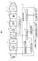
図6に示すように、本実施形態に係るX線高電圧装置は、X線の曝射条件に応じて定められる電圧目標値を記憶した電圧目標値テーブル16を備えている。
電圧目標値テーブル16には、複数種類の曝射条件が記憶され、曝射条件毎に、X線が曝射されていない時(X線曝射判定回路14がX線曝射停止信号を出力した際)の電圧目標値が夫々対応付けられて記憶されている。X線が曝射されていない時の電圧目標値は、X線曝射時(X線曝射判定回路14がX線曝射信号を出力した際)の電圧目標値(初期値)よりも低い電圧値となっており、この初期値よりも低電圧の電圧目標値に切り替えられるのは上述の第1の実施形態1の場合と同様の理由から、曝射終了後の所定時間(例えば1秒)となっている。As shown in FIG. 6, the X-ray high voltage apparatus according to this embodiment includes a voltage target value table 16 that stores voltage target values determined according to the X-ray exposure conditions.
The voltage target value table 16 stores a plurality of types of exposure conditions, and when no X-rays are emitted for each exposure condition (the X-ray
そして、電圧目標値テーブル16は、本実施形態に係るX線高電圧装置が適用されるX線CT装置等に備えられる曝射条件入力部57から曝射条件の入力を受け付ける。 The voltage target value table 16 receives an exposure condition input from an exposure
本実施形態に係るX線高電圧装置では、X線曝射判定回路14がX線高電圧装置動作トリガ回路56から受信したトリガ信号に基づいて、X線曝射有の場合にはX線曝射信号を、又は、X線曝射無の場合には、X線曝射停止信号を出力電圧制御部12に出力する。 In the X-ray high voltage apparatus according to the present embodiment, the X-ray
出力電圧制御部12は、X線曝射判定回路14による判定結果に応じて、電圧目標値テーブル16のうち曝射条件に応じた電圧目標値を読み出す。
すなわち、出力電圧制御部12が、X線曝射判定回路14から曝射有を示すX線曝射信号を受信している場合には、電圧目標値テーブル16から読み出された曝射条件に応じた電圧目標値の初期値(例えば、750V)を維持するようにDCバスコンデンサ3の電圧を制御する。
一方、出力電圧制御部12が、X線曝射判定回路14から曝射無を示すX線曝射停止信号を受信した場合には、電圧目標値テーブル16から読み出された曝射条件に対応するX線が曝射されていない時の電圧目標値に切り替える。The output
That is, when the output
On the other hand, when the output
このように、本実施形態によれば、X線の曝射の判定結果に応じて、X線曝射がオフとなった際に直ちに電圧目標値を、X線曝射がオンの際の電圧目標値よりも低い電圧値に切り替える。このため、X線の曝射が終了し、負荷としてのX線管への電力供給が不要となり、実質的に軽負荷ないしは無負荷となった場合でも、直流変換部における電圧の跳ね上がりを抑制することができる。これにより、直流変換部を構成するIGBTモジュール等の部品の損傷を防止することができ、X線高電圧装置の信頼性を向上させることができる。 Thus, according to the present embodiment, the voltage target value is set immediately when X-ray exposure is turned off, and the voltage when X-ray exposure is turned on, according to the determination result of X-ray exposure. Switch to a voltage value lower than the target value. For this reason, even when the X-ray exposure is completed and the power supply to the X-ray tube as a load is unnecessary, even if the load is substantially light or no load, the jumping of the voltage in the DC converter is suppressed. be able to. Thereby, damage to components, such as IGBT module which comprises a direct-current converter, can be prevented, and the reliability of an X-ray high voltage device can be improved.
また、本実施形態においては、X線の曝射条件によって変動する、直流変換部の出力電圧、すなわち、DCバスコンデンサの電圧の跳ね上がりに対しても適切に抑制することができる。直流変換部の出力電圧は、X線曝射時が軽負荷である場合には曝射終了時の電圧の跳ね上がりは小さい。しかしながら、X線曝射時に重負荷であった場合には、曝射終了時の跳ね上がりが大きくなってしまう。そこで、本実施形態のように、曝射条件に応じて電圧目標値を設定することで、直流変換部の出力電圧を良好に制御することができ、出力電圧を下げ過ぎることなく、また、電圧の跳ねあがりを確実に防止することができる。 Further, in the present embodiment, it is possible to appropriately suppress the output voltage of the DC converter, that is, the jump of the voltage of the DC bus capacitor, which varies depending on the X-ray exposure conditions. When the X-ray exposure is a light load, the output voltage of the DC conversion unit has a small voltage jump at the end of the exposure. However, if there is a heavy load at the time of X-ray exposure, the jump at the end of the exposure will increase. Therefore, as in this embodiment, by setting the voltage target value according to the exposure conditions, the output voltage of the DC conversion unit can be controlled well, without reducing the output voltage too much, and the voltage Can be reliably prevented.
(変形例)
上述した各実施形態においては、X線曝射がオンからオフに切り替わった際に、これにあわせて電圧目標値も切り替えることにより、直流変換部の出力電圧を一定に保つように制御する例について説明した。
X線曝射がオフとなるのは、X線高電圧装置が適用されるX線CT装置などにおける撮影終了に限られず、例えば、X線曝射中にX線高電圧装置が故障した場合や、X線CT装置が故障した場合等も考えられる。
このような場合にも、X線曝射が終了し、直流変換部にとっては無負荷状態となる。従って、出力電圧制御部12にエラー信号を入力し、X線高電圧装置が故障した場合にエラー信号をオンとするように構成する。出力電圧制御部12では、エラー信号のオンを受けて直流変換部の電圧目標値を低下させることで、X線高電圧装置が故障により動作を停止した場合にも、直流変換部における電圧の跳ね上がりを抑制することができる。なお、X線高電圧装置におけるエラー信号は、X線高電圧装置の全体を制御する制御部(図示せず)から入力されるように構成することができる。また、X線CT装置の故障を示すエラー信号の場合も、X線高電圧装置の制御部を介して出力電圧制御部12に入力されるように構成することができる。(Modification)
In each of the above-described embodiments, when X-ray exposure is switched from on to off, the voltage target value is also switched in accordance with this, thereby controlling the output voltage of the DC converter to be constant. explained.
The X-ray exposure is turned off not only at the end of imaging in an X-ray CT apparatus or the like to which the X-ray high voltage apparatus is applied. For example, when the X-ray high voltage apparatus breaks down during the X-ray exposure, A case where the X-ray CT apparatus breaks down is also conceivable.
Even in such a case, the X-ray exposure ends, and the DC converter is in a no-load state. Therefore, an error signal is input to the output
<第3の実施形態>
本実施形態に係るX線高電圧装置は、X線CT装置に適用され、X線CT装置において心臓撮影を行う場合に、X線高電圧装置の直流変換部における出力電力を制御する。<Third Embodiment>
The X-ray high voltage apparatus according to the present embodiment is applied to an X-ray CT apparatus, and controls output power in a DC conversion unit of the X-ray high voltage apparatus when cardiac imaging is performed in the X-ray CT apparatus.
X線CT装置における心臓撮影時は、被検体の心拍に同期させて管電流を低管電流から高管電流に瞬時に上昇させる。つまり、X線高電圧装置の直流変換部にとっては、撮影中に負荷が重負荷から軽負荷、または軽負荷から重負荷に瞬時に切り替わるので、直流変換部の電圧目標値を切り替えずに制御を実施すると高管電流から低管電流に切り替わった際に、DCバスコンデンサの電圧の跳ね上がりが発生してしまう。 At the time of cardiac imaging in the X-ray CT apparatus, the tube current is instantaneously increased from a low tube current to a high tube current in synchronization with the heartbeat of the subject. In other words, for the DC converter of the X-ray high-voltage device, the load is instantaneously switched from heavy load to light load or from light load to heavy load during imaging. Therefore, control is performed without switching the voltage target value of the DC converter. When implemented, when the high tube current is switched to the low tube current, the voltage of the DC bus capacitor jumps.
このため、本実施形態においては、X線CT装置の心電計から心拍タイミング信号がX線高電圧装置に入力され、X線高電圧装置において、心拍に同期させて電圧目標値を切り替える。従って、本実施形態に係るX線高電圧装置は、図7に示すように、管電流指令値作成部17及び管電流判定回路18を備えている。その他、上述した第1及び第2の実施形態に係るX線高電圧装置と同一の構成には同符号を付し、その説明を省略する。 For this reason, in this embodiment, a heartbeat timing signal is input from the electrocardiograph of the X-ray CT apparatus to the X-ray high voltage apparatus, and the X-ray high voltage apparatus switches the voltage target value in synchronization with the heartbeat. Therefore, the X-ray high voltage apparatus according to this embodiment includes a tube current command
管電流指令値作成部17は、X線CT装置から入力された心拍タイミング信号に同期する管電流を出力するための管電流指令値を生成し、管電流判定回路18に出力する。
管電流判定回路18は、管電流指令値作成部17から受け取った管電流指令値に基づいて、高管電流から低管電流に切り替わるタイミングを判定し、タイミング信号を出力電圧目標値設定部15に出力する。The tube current command
The tube
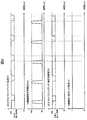
出力電圧目標値設定部15は、X線曝射判定回路14からX線曝射信号が入力されている場合において、管電流判定回路18から入力されたタイミング信号に従って、すなわち、高管電流から低管電流に切り替わるタイミングに同期させて出力電圧目標値を任意の値まで下げるように制御を行う(図8参照)。
任意の値まで出力電圧を下げた後に、次の曝射に備えて出力電圧目標値を初期値に戻す必要があることは上述した第1の実施形態及び第2の実施形態に記載した通りであり、心拍に同期させる場合は、低管電流から高管電流に移る動作が「次の曝射」に相当する。心拍に同期させてスキャンを実施する場合、低管電流から高管電流に移る間隔は被検体の心拍速度により異なる。そのため、心拍に同期させたX線曝射を実施する場合には、例えば、心拍が早い被検体を考慮して、出力電圧目標値を50msの間だけ任意の値まで下げ、50ms経過した後に初期値に戻す。When the X-ray exposure signal is input from the X-ray
As described in the first and second embodiments, the output voltage target value needs to be returned to the initial value in preparation for the next exposure after the output voltage is lowered to an arbitrary value. In the case of synchronizing with the heartbeat, the operation of shifting from the low tube current to the high tube current corresponds to “next exposure”. When scanning is performed in synchronization with the heartbeat, the interval from the low tube current to the high tube current varies depending on the heart rate of the subject. Therefore, when performing X-ray exposure synchronized with the heartbeat, for example, considering an object with a fast heartbeat, the output voltage target value is lowered to an arbitrary value for 50 ms, and after 50 ms has elapsed, Return to value.
このように、心臓撮影機能を有するX線CT装置に本実施形態に係るX線高電圧装置を適用した場合に、心拍に同期してタイミング信号を生成し、このタイミング信号に基づいて出力電圧目標値を制御することで、DCバスコンデンサの電圧の跳ね上がりを抑制することができる。 As described above, when the X-ray high voltage apparatus according to the present embodiment is applied to an X-ray CT apparatus having a cardiac imaging function, a timing signal is generated in synchronization with the heartbeat, and an output voltage target is based on the timing signal. By controlling the value, the jump of the voltage of the DC bus capacitor can be suppressed.
<第4の実施形態>
以下、第4の実施形態として、上記した第1〜第3の実施形態に係るX線高電圧装置を適用したX線撮影装置の一例であるX線CT(Computer Tomography)装置について説明する。<Fourth Embodiment>
Hereinafter, as a fourth embodiment, an X-ray CT (Computer Tomography) apparatus, which is an example of an X-ray imaging apparatus to which the X-ray high voltage apparatus according to the first to third embodiments described above is applied, will be described.
図9に、X線CT装置301の全体構成図を示す。X線CT装置301はスキャンガントリ部300と操作卓320とを備えている。
スキャンガントリ部300は、X線管8と、回転円盤302と、コリメータ303と、X線検出器306と、データ収集装置307と、寝台305と、ガントリ制御装置308と、寝台制御装置309と、X線高電圧装置207と、を備えている。FIG. 9 shows an overall configuration diagram of the
The
X線高電圧装置207には、上述した第1〜第3の実施形態の何れかのX線高電圧装置を適用する。X線高電圧装置のうち、X線管8と高電圧発生部53は、回転円盤302に搭載され、回転円盤302と共に回転する。他の構成は、回転円盤302には搭載されず、静止している。 As the X-ray
コリメータ303は、X線管8から照射されるX線の照射範囲を制御する。
X線検出器306は、X線管8と対向配置され被検体を透過したX線を検出する。
回転円盤302は、寝台305上に搭載された被検体が入る開口部304を備えると共に、X線管8とX線検出器306を搭載し、被検体の周囲を回転する駆動部を備える。
X線検出器306は、複数の検出素子を回転円盤302の回転方向(チャンネル方向ともいう)に配置した構成である。複数の検出素子は、回転方向の並びを1列としたときに、この列を回転円盤302の回転軸方向(スライス方向ともいう)に多列(例えば64列)並べたものであっても良い。The
The
The
The
データ収集装置307は、X線検出器306で検出されたX線を所定の電気信号に変換する装置である。
ガントリ制御装置308は回転円盤302の回転を制御する装置である。
寝台制御装置309は、寝台305の上下動および前後動(回転円盤302の回転軸方向の移動)を制御する装置である。The
The
The
操作卓320は、入力装置321と、画像演算装置322と、表示装置325と、記憶装置323と、システム制御装置324とを備えている。
入力装置321は、被検体氏名、検査日時、撮影条件などを入力するための装置であり、具体的にはキーボードやポインティングデバイス等である。The
The
画像演算装置322は、データ収集装置307から送出される計測データを演算処理してCT画像再構成を行う装置であり、具体的には演算処理を実行するCPU、若しくは専用の演算回路である。
表示装置325は、画像演算装置322で作成されたCT画像を表示する装置である。記憶装置323は、データ収集装置307で収集されたデータ及び画像演算装置322で作成されたCT画像の画像データを記憶する装置である。
システム制御装置324は、これらの装置及びガントリ制御装置308と寝台制御装置309とX線高電圧装置207を制御する装置である。The
The
The
X線管8には、入力装置321から入力された撮影条件(管電圧等)になるように、X線高電圧装置207によって制御された管電流および管電圧が供給される。X線高電圧装置207の構成および動作は、第1〜第3の実施形態で説明した通りであるので、説明を省略する。 The
X線管8から照射され被検体を透過したX線は、X線検出器306のX線検出素子によって検出される。この間、回転円盤302は、X線管8とX線検出器306とを回転させることにより、被検体の各方向からX線が照射され、検出されるようにする。回転円盤302の回転速度は、入力装置321から入力された撮影条件(スキャン速度など)となるようにガントリ制御装置308により制御される。また、X線が照射されて検出されている間、寝台305は、寝台制御装置309の制御により、被検体を体軸方向に移動させ、入力装置321から入力された撮影条件(らせんピッチなど)となるように動作する。 X-rays irradiated from the
X線検出器306の出力信号は、データ収集装置307により投影データとして収集される。データ収集装置307で収集された投影データは、画像演算装置322へ送出される。画像演算装置322は、投影データを再構成演算してCT画像とする。再構成されたCT画像は表示装置325に表示され、また撮影条件とともに画像データとして記憶装置323に記憶される。 The output signal of the
本実施形態のX線CT装置に、本発明のX線高電圧装置207を用いることにより、X線高電圧装置の直流変換部における電圧の跳ね上がりを抑制することができる。そして、直流変換部における電圧の跳ね上がりを抑制することで、直流変換部を構成するIGBTモジュール等の部品の損傷を防止することができ、X線高電圧装置の信頼性を向上させることができる。 By using the X-ray
2・・・直流変換回路、3・・・DCバスコンデンサ、5・・・高電圧変圧器、6・・・多倍圧整流回路、7・・・平滑コンデンサ、8・・・X線管、9・・・電流検出回路、10・・・入力電流制御部、11・・・出力電圧検出回路、12・・・出力電圧制御部、13・・・直流変換回路ドライブ回路、14・・・X線曝射判定回路、15・・・出力電圧目標値設定部、51・・・直流変換部、52・・・インバータ部、53・・・高電圧発生部、54・・・陽極駆動回路、5・・・直流電圧制御回路、56・・・X線高電圧装置動作トリガ回路2 ... DC converter circuit, 3 ... DC bus capacitor, 5 ... high voltage transformer, 6 ... multiple voltage rectifier circuit, 7 ... smoothing capacitor, 8 ... X-ray tube, DESCRIPTION OF
Claims (7)
Translated fromJapanese前記直流変換回路の出力の目標値である電圧目標値を設定する電圧目標値設定部と、
前記電圧目標値に一致するように前記直流変換回路の出力電圧を制御する出力電圧制御部と、を備え、
前記出力電圧制御部が、前記X線管の曝射条件の変動に同期して、電圧目標値を切り替えて前記直流変換回路の出力電圧を制御するX線高電圧装置。A DC conversion circuit that converts a voltage supplied from an AC power source into a DC voltage, and outputs DC power to a resonance circuit including an X-ray tube as a load;
A voltage target value setting unit for setting a voltage target value that is a target value of the output of the DC converter circuit;
An output voltage controller that controls the output voltage of the DC converter circuit so as to match the voltage target value,
An X-ray high-voltage apparatus in which the output voltage control unit controls the output voltage of the DC conversion circuit by switching a voltage target value in synchronization with a change in exposure conditions of the X-ray tube.
該判定回路によりX線の曝射が終了したと判定された場合に、X線曝射時よりも低電圧の電圧目標値に切り替えて前記直流変換回路の出力電圧を制御する請求項1記載のX線高電圧装置。The output voltage control unit includes a determination circuit that determines whether or not the X-ray tube is exposed;
2. The output voltage of the DC converter circuit is controlled by switching to a voltage target value lower than that at the time of X-ray exposure when the determination circuit determines that X-ray exposure has ended. X-ray high voltage device.
前記出力電圧制御部が、前記管電流指令信号に基づいて、前記X線管へ供給される管電流が高管電流から低管電流に切り替わるタイミングに同期させて、低管電流時に高管電流時よりも低電圧の電圧目標値を切り替えて前記直流変換回路の出力電圧を制御する請求項1記載のX線高電圧装置。A tube current command generator for generating a tube current command signal for generating a tube current synchronized with the heartbeat of the subject;
Based on the tube current command signal, the output voltage control unit synchronizes with the timing at which the tube current supplied to the X-ray tube is switched from a high tube current to a low tube current. The X-ray high voltage apparatus according to claim 1, wherein the output voltage of the DC conversion circuit is controlled by switching a voltage target value of a lower voltage.
Priority Applications (1)
| Application Number | Priority Date | Filing Date | Title |
|---|---|---|---|
| JP2016040086AJP2017157433A (en) | 2016-03-02 | 2016-03-02 | X-ray high voltage apparatus and X-ray CT apparatus |
Applications Claiming Priority (1)
| Application Number | Priority Date | Filing Date | Title |
|---|---|---|---|
| JP2016040086AJP2017157433A (en) | 2016-03-02 | 2016-03-02 | X-ray high voltage apparatus and X-ray CT apparatus |
Publications (1)
| Publication Number | Publication Date |
|---|---|
| JP2017157433Atrue JP2017157433A (en) | 2017-09-07 |
Family
ID=59809979
Family Applications (1)
| Application Number | Title | Priority Date | Filing Date |
|---|---|---|---|
| JP2016040086APendingJP2017157433A (en) | 2016-03-02 | 2016-03-02 | X-ray high voltage apparatus and X-ray CT apparatus |
Country Status (1)
| Country | Link |
|---|---|
| JP (1) | JP2017157433A (en) |
Cited By (1)
| Publication number | Priority date | Publication date | Assignee | Title |
|---|---|---|---|---|
| CN109166436A (en)* | 2018-09-25 | 2019-01-08 | 泰山医学院 | X-ray machine three compensates imitative experimental appliance |
- 2016
- 2016-03-02JPJP2016040086Apatent/JP2017157433A/enactivePending
Cited By (2)
| Publication number | Priority date | Publication date | Assignee | Title |
|---|---|---|---|---|
| CN109166436A (en)* | 2018-09-25 | 2019-01-08 | 泰山医学院 | X-ray machine three compensates imitative experimental appliance |
| CN109166436B (en)* | 2018-09-25 | 2020-09-01 | 山东第一医科大学(山东省医学科学院) | Three-compensation simulation experiment device for X-ray machine |
Similar Documents
| Publication | Publication Date | Title |
|---|---|---|
| WO2011099472A1 (en) | Power conversion device, x-ray ct device, and x-ray image taking device | |
| JP5588875B2 (en) | Phase shift type inverter circuit, X-ray high voltage apparatus, X-ray CT apparatus, and X-ray imaging apparatus using the same | |
| WO2014109400A1 (en) | X-ray computer tomography device and x-ray generation device | |
| US9900971B2 (en) | X-ray CT apparatus, X-ray high-voltage device, and X-ray scanning device | |
| US10595389B2 (en) | X-ray high voltage generator, X-ray imaging apparatus, assessing circuit, and medical power supply device | |
| JP4526130B2 (en) | Power conversion device, inverter X-ray high voltage device, X-ray fluoroscopic device, X-ray CT device, MRI device | |
| JP2018198204A (en) | X-ray diagnosis system and anode rotary coil driving device | |
| JP2017157433A (en) | X-ray high voltage apparatus and X-ray CT apparatus | |
| JP5685449B2 (en) | X-ray high voltage apparatus and X-ray CT apparatus | |
| JP6479438B2 (en) | X-ray high voltage apparatus, X-ray computed tomography apparatus, and X-ray diagnostic apparatus | |
| JP6095281B2 (en) | X-ray generator and mobile X-ray imaging apparatus | |
| JP6139262B2 (en) | X-ray high voltage device | |
| JP4454079B2 (en) | X-ray high voltage apparatus and X-ray apparatus | |
| JP5089834B2 (en) | X-ray generator and X-ray CT apparatus using the same | |
| JP6162108B2 (en) | Power conversion apparatus and X-ray imaging apparatus | |
| JP6670617B2 (en) | High voltage generator and X-ray CT system | |
| JP6172923B2 (en) | X-ray diagnostic imaging equipment | |
| JP7390881B2 (en) | Power conversion equipment, X-ray imaging equipment, motor drive equipment | |
| JP2016073382A (en) | X-ray photographing device | |
| JP5637697B2 (en) | X-ray high voltage apparatus, X-ray apparatus, and X-ray diagnostic apparatus using the same | |
| WO2001086791A1 (en) | X-ray generator and x-ray ct apparatus comprising the same | |
| JP5660763B2 (en) | X-ray CT system | |
| JP2022115528A (en) | X-ray high voltage device and X-ray imaging device | |
| WO2023068342A1 (en) | Control device, control method, and control program | |
| CN119678654A (en) | Method and system for boosting power of a gantry of a medical imaging system |