JP2017156388A - Luminous flux diameter expansion element and image display device - Google Patents
Luminous flux diameter expansion element and image display deviceDownload PDFInfo
- Publication number
- JP2017156388A JP2017156388AJP2016036787AJP2016036787AJP2017156388AJP 2017156388 AJP2017156388 AJP 2017156388AJP 2016036787 AJP2016036787 AJP 2016036787AJP 2016036787 AJP2016036787 AJP 2016036787AJP 2017156388 AJP2017156388 AJP 2017156388A
- Authority
- JP
- Japan
- Prior art keywords
- light
- incident
- image
- diffraction grating
- grating
- Prior art date
- Legal status (The legal status is an assumption and is not a legal conclusion. Google has not performed a legal analysis and makes no representation as to the accuracy of the status listed.)
- Granted
Links
Images


Classifications
- G—PHYSICS
- G02—OPTICS
- G02B—OPTICAL ELEMENTS, SYSTEMS OR APPARATUS
- G02B27/00—Optical systems or apparatus not provided for by any of the groups G02B1/00 - G02B26/00, G02B30/00
- G02B27/01—Head-up displays
- G02B27/017—Head mounted
- G02B27/0172—Head mounted characterised by optical features
- G—PHYSICS
- G02—OPTICS
- G02B—OPTICAL ELEMENTS, SYSTEMS OR APPARATUS
- G02B5/00—Optical elements other than lenses
- G02B5/18—Diffraction gratings
- G02B5/1842—Gratings for image generation
- G—PHYSICS
- G02—OPTICS
- G02B—OPTICAL ELEMENTS, SYSTEMS OR APPARATUS
- G02B5/00—Optical elements other than lenses
- G02B5/18—Diffraction gratings
- G02B5/1866—Transmission gratings characterised by their structure, e.g. step profile, contours of substrate or grooves, pitch variations, materials
- G—PHYSICS
- G02—OPTICS
- G02B—OPTICAL ELEMENTS, SYSTEMS OR APPARATUS
- G02B6/00—Light guides; Structural details of arrangements comprising light guides and other optical elements, e.g. couplings
- G02B6/10—Light guides; Structural details of arrangements comprising light guides and other optical elements, e.g. couplings of the optical waveguide type
- G02B6/12—Light guides; Structural details of arrangements comprising light guides and other optical elements, e.g. couplings of the optical waveguide type of the integrated circuit kind
- G02B6/122—Basic optical elements, e.g. light-guiding paths
- G02B6/124—Geodesic lenses or integrated gratings
- G—PHYSICS
- G02—OPTICS
- G02B—OPTICAL ELEMENTS, SYSTEMS OR APPARATUS
- G02B5/00—Optical elements other than lenses
- G02B5/18—Diffraction gratings
- G02B2005/1804—Transmission gratings
- G—PHYSICS
- G02—OPTICS
- G02B—OPTICAL ELEMENTS, SYSTEMS OR APPARATUS
- G02B27/00—Optical systems or apparatus not provided for by any of the groups G02B1/00 - G02B26/00, G02B30/00
- G02B27/01—Head-up displays
- G02B27/0101—Head-up displays characterised by optical features
- G02B2027/011—Head-up displays characterised by optical features comprising device for correcting geometrical aberrations, distortion
- G—PHYSICS
- G02—OPTICS
- G02B—OPTICAL ELEMENTS, SYSTEMS OR APPARATUS
- G02B27/00—Optical systems or apparatus not provided for by any of the groups G02B1/00 - G02B26/00, G02B30/00
- G02B27/01—Head-up displays
- G02B27/0101—Head-up displays characterised by optical features
- G02B2027/0112—Head-up displays characterised by optical features comprising device for genereting colour display
- G—PHYSICS
- G02—OPTICS
- G02B—OPTICAL ELEMENTS, SYSTEMS OR APPARATUS
- G02B27/00—Optical systems or apparatus not provided for by any of the groups G02B1/00 - G02B26/00, G02B30/00
- G02B27/01—Head-up displays
- G02B27/0101—Head-up displays characterised by optical features
- G02B2027/0118—Head-up displays characterised by optical features comprising devices for improving the contrast of the display / brillance control visibility
- G—PHYSICS
- G02—OPTICS
- G02B—OPTICAL ELEMENTS, SYSTEMS OR APPARATUS
- G02B27/00—Optical systems or apparatus not provided for by any of the groups G02B1/00 - G02B26/00, G02B30/00
- G02B27/01—Head-up displays
- G02B27/0101—Head-up displays characterised by optical features
- G02B2027/013—Head-up displays characterised by optical features comprising a combiner of particular shape, e.g. curvature
- G—PHYSICS
- G02—OPTICS
- G02B—OPTICAL ELEMENTS, SYSTEMS OR APPARATUS
- G02B27/00—Optical systems or apparatus not provided for by any of the groups G02B1/00 - G02B26/00, G02B30/00
- G02B27/01—Head-up displays
- G02B27/017—Head mounted
- G02B2027/0178—Eyeglass type
- G—PHYSICS
- G02—OPTICS
- G02B—OPTICAL ELEMENTS, SYSTEMS OR APPARATUS
- G02B26/00—Optical devices or arrangements for the control of light using movable or deformable optical elements
- G02B26/08—Optical devices or arrangements for the control of light using movable or deformable optical elements for controlling the direction of light
- G02B26/10—Scanning systems
- G02B26/105—Scanning systems with one or more pivoting mirrors or galvano-mirrors
Landscapes
- Physics & Mathematics (AREA)
- General Physics & Mathematics (AREA)
- Optics & Photonics (AREA)
- Engineering & Computer Science (AREA)
- Microelectronics & Electronic Packaging (AREA)
- Diffracting Gratings Or Hologram Optical Elements (AREA)
Abstract
Translated fromJapaneseDescription
Translated fromJapanese本発明は、光束径拡大素子及び画像表示装置に関するものである。 The present invention relates to a beam diameter expanding element and an image display device.
近年、ヘッドマウントディスプレイ等の装着型の画像表示装置が注目されている。このようなヘッドマウントディスプレイとして、レーザービームをスキャンして目の網膜上に画像を描画するものが知られている(例えば、特許文献1参照)。 In recent years, a wearable image display device such as a head-mounted display has attracted attention. As such a head-mounted display, one that scans a laser beam and draws an image on the retina of the eye is known (for example, see Patent Document 1).
このヘッドマウントディスプレイでは、回折格子によってレーザービームを複数のビームに分割することで画像光を拡大し、鑑賞者の眼が多少動いても瞳に入るレーザービームを確保し、画像を視認させているようにしている。 In this head-mounted display, the image light is expanded by dividing the laser beam into a plurality of beams by a diffraction grating, and the laser beam entering the pupil is secured even if the viewer's eyes move slightly, and the image is visually recognized. I am doing so.
しかしながら、レーザービームを用いる方式では画像光が瞳径に比べて小さくなるため、上記従来技術では画像光を十分に拡大させることが難しかった。そこで、レーザービームを用いる方式のように画像光が瞳径よりも十分小さい場合であっても、画像光を瞳に入射させることができる新たな技術の提供が望まれている。 However, in the method using a laser beam, the image light is smaller than the pupil diameter, so that it has been difficult to sufficiently expand the image light with the above-described conventional technology. Therefore, it is desired to provide a new technique that allows the image light to be incident on the pupil even when the image light is sufficiently smaller than the pupil diameter as in the method using a laser beam.
本発明はこのような事情に鑑みてなされたものであって、光を拡大して瞳に良好に入射させることが可能な光束径拡大素子及び画像表示装置を提供することを目的とする。 The present invention has been made in view of such circumstances, and it is an object of the present invention to provide a light beam diameter enlarging element and an image display device capable of enlarging light and allowing it to enter the pupil satisfactorily.
本発明の第1態様に従えば、光入射面及び光出射面を有し、厚さが0.2mm〜0.8mmの導光板と、前記光入射面に設けられた入射側回折格子と、前記光出射面に設けられ、前記入射側回折格子と同じ格子周期となるように設けられた出射側回折格子と、を備え、前記入射側回折格子は、前記出射側回折格子よりも小さく、前記入射側回折格子の格子周期は、前記入射側回折格子で回折した+1次回折光及び−1次回折光の前記導光板内における回折角のうち小さい方の回折角が、前記導光板の臨界角よりも大きくなる周期である光束径拡大素子が提供される。 According to the first aspect of the present invention, a light guide plate having a light incident surface and a light output surface and having a thickness of 0.2 mm to 0.8 mm, an incident side diffraction grating provided on the light incident surface, An exit side diffraction grating provided on the light exit surface and provided to have the same grating period as the entrance side diffraction grating, the entrance side diffraction grating being smaller than the exit side diffraction grating, The grating period of the incident side diffraction grating is such that the smaller one of the diffraction angles of the + 1st order diffracted light and the −1st order diffracted light diffracted by the incident side diffraction grating in the light guide plate is larger than the critical angle of the light guide plate. A light beam diameter enlarging element having an increasing period is provided.
第1態様に係る光束径拡大素子によれば、入射面に入射する1本の光線を該入射面に対する入射角度を保った状態で複数の光線に増やすことができる。導光板の厚さが0.2mm〜0.8mmとされるため、複数の光線の間隔を目の瞳孔直径よりも小さい間隔(2mm以下)に良好に調整することができる。
よって、鑑賞者の眼が動く場合でも、眼の瞳孔に光線の少なくとも1本を入射させることができる。According to the light beam diameter enlarging element according to the first aspect, one light beam incident on the incident surface can be increased to a plurality of light beams while maintaining an incident angle with respect to the incident surface. Since the thickness of the light guide plate is 0.2 mm to 0.8 mm, it is possible to satisfactorily adjust the interval between the plurality of light rays to an interval (2 mm or less) smaller than the pupil diameter of the eyes.
Therefore, even when the viewer's eyes move, at least one light beam can be incident on the pupil of the eye.
上記第1態様において、前記光入射面に入射する入射光の波長帯域のうち最も短い波長をλminとし、前記光入射面に対する前記入射光の入射角度の最大角度の絶対値を|θmax|とし、前記光入射面の格子周期をPとしたとき、前記光入射面の格子周期が、P ≦ λmin/(sin|θmax|+1)を満たすのが好ましい。
この構成によれば、入射側回折格子に入射した光を導光板内において全反射により伝播させることができる。これにより、光射出面から射出される光束径を良好に拡大させることができる。In the first aspect, the shortest wavelength in the wavelength band of incident light incident on the light incident surface is λmin, and the absolute value of the maximum angle of incidence of the incident light with respect to the light incident surface is | θmax | When the grating period of the light incident surface is P, the grating period of the light incident surface preferably satisfies P ≦ λmin / (sin | θmax | +1).
According to this configuration, the light incident on the incident side diffraction grating can be propagated by total reflection in the light guide plate. Thereby, the diameter of the light beam emitted from the light exit surface can be favorably enlarged.
上記第1態様において、前記出射側回折格子の格子高さは、前記入射側回折格子の格子高さよりも低いのが好ましい。
この構成によれば、出射側回折格子の回折効率が入射側回折格子の回折効率よりも低く設定される。よって、導光板内を伝搬する光を出射側回折格子により出射面から複数個所で出射させることができる。これにより、光束径拡大機能を良好に得ることができる。In the first aspect, it is preferable that a grating height of the output side diffraction grating is lower than a grating height of the incident side diffraction grating.
According to this configuration, the diffraction efficiency of the exit side diffraction grating is set lower than that of the entrance side diffraction grating. Therefore, the light propagating in the light guide plate can be emitted from the exit surface at a plurality of locations by the exit side diffraction grating. Thereby, the light beam diameter enlarging function can be obtained satisfactorily.
本発明の第2態様に従えば、画像光を射出する画像光生成部と、上記第1態様の光束径拡大素子から構成される、画像光拡大素子と、を備える画像表示装置が提供される。 According to a second aspect of the present invention, there is provided an image display device comprising: an image light generating unit that emits image light; and an image light enlarging element that includes the light beam diameter enlarging element of the first aspect. .
第2態様に係る画像表示装置によれば、上記光束拡大素子を備えるので、鑑賞者の瞳が動く場合でも、画像光を良好に視認させることができる。 According to the image display device according to the second aspect, since the light beam enlarging element is provided, the image light can be viewed well even when the viewer's pupil moves.
上記第2態様において、前記画像光は異なる波長帯の光を含み、前記画像光拡大素子を複数備えており、前記複数の画像光拡大素子の各々の前記入射側回折格子の格子周期が互いに異なる周期であるのが好ましい。
この構成によれば、異なる波長帯の光のそれぞれの導光板での回折角を同一にすることができる。
さらに、前記複数の画像光拡大素子の各々の導光板は、互いに厚さが同じ厚さとなるように設けられているのが望ましい。
このようにすれば、光の波長帯によらず同一の位置から出射させることができる。In the second aspect, the image light includes light in different wavelength bands, includes a plurality of the image light expansion elements, and the grating periods of the incident-side diffraction gratings of the plurality of image light expansion elements are different from each other. A period is preferred.
According to this configuration, it is possible to make the diffraction angles of the light beams of different wavelength bands the same.
Furthermore, it is desirable that the light guide plates of each of the plurality of image light expansion elements are provided to have the same thickness.
If it does in this way, it can be made to radiate | emit from the same position irrespective of the wavelength band of light.
上記第2態様において、前記複数の画像光拡大素子の各々の前記入射側回折格子の格子周期は、前記画像光生成部側から離間するにつれて大きくなるのが好ましい。
この構成によれば、不要な回折光の発生を抑制することができる。In the second aspect, it is preferable that the grating period of the incident-side diffraction grating of each of the plurality of image light expanding elements increases as the distance from the image light generation unit side increases.
According to this configuration, generation of unnecessary diffracted light can be suppressed.
上記第2態様において、前記複数の画像光拡大素子は、第1画像光拡大素子、第2画像光拡大素子及び第3画像光拡大素子を含み、前記第1画像光拡大素子、前記第2画像光拡大素子及び前記第3画像光拡大素子の各々の前記入射側回折格子の格子周期は、各々の前記入射側回折格子で回折した回折光の回折角が同じ角度となるような周期であり、前記画像光は、前記第1画像光拡大素子に対応する第1波長帯の光、前記第2画像光拡大素子に対応する第2波長帯の光及び前記第3画像光拡大素子に対応する第3波長帯の光を含むのが好ましい。
この構成によれば、カラー画像を表示することができる。In the second aspect, the plurality of image light expansion elements include a first image light expansion element, a second image light expansion element, and a third image light expansion element, and the first image light expansion element and the second image The grating period of the incident side diffraction grating of each of the light magnifying element and the third image light magnifying element is such that the diffraction angles of the diffracted light diffracted by each of the incident side diffraction gratings are the same angle, The image light includes light in a first wavelength band corresponding to the first image light expansion element, light in a second wavelength band corresponding to the second image light expansion element, and first light corresponding to the third image light expansion element. It is preferable to include light in three wavelength bands.
According to this configuration, a color image can be displayed.
上記第2態様において、前記複数の画像光拡大素子から射出された光が入射する接眼光学系をさらに備え、前記接眼光学系は、光透過性を有するのが好ましい。
この構成によれば、画像光とともに外光(シースルー光)を視認することができる。In the second aspect, it is preferable that the eyepiece optical system further includes an eyepiece optical system on which light emitted from the plurality of image light expansion elements is incident, and the eyepiece optical system preferably has light transmittance.
According to this configuration, external light (see-through light) can be visually recognized together with image light.
以下、本発明の実施の形態について、図面を参照して詳細に説明する。なお、以下の説明で用いる図面は、特徴をわかりやすくするために、便宜上特徴となる部分を拡大して示している場合があり、各構成要素の寸法比率などが実際と同じであるとは限らない。 Hereinafter, embodiments of the present invention will be described in detail with reference to the drawings. In addition, in the drawings used in the following description, in order to make the features easy to understand, there are cases where the portions that become the features are enlarged for the sake of convenience, and the dimensional ratios of the respective components are not always the same as the actual ones. Absent.
(第1実施形態)
本実施形態の画像表示装置は、使用者が頭に装着して使用するヘッドマウントディスプレイの一例である。
以下の説明では、ヘッドマウントディスプレイ(Head Mounted Display)を、HMDと略記する。
図1は、使用者が本実施形態のHMDを装着した状態を示す図である。
図2は、本実施形態のHMDの斜視図である。(First embodiment)
The image display apparatus according to the present embodiment is an example of a head mounted display that is used by a user wearing on the head.
In the following description, a head mounted display is abbreviated as HMD.
FIG. 1 is a diagram illustrating a state in which a user wears the HMD of the present embodiment.
FIG. 2 is a perspective view of the HMD of this embodiment.
図1に示すように、本実施形態のHMD300は、使用者が眼鏡を掛ける感覚で頭部に装着して使用するものである。本実施形態のHMD300は、シースルー型(透過型)のHMDである。本実施形態のHMD300によれば、使用者は画像表示部により生成された画像を視認でき、かつ、HMD300の外部の景色等の外界の像も視認できる。 As shown in FIG. 1, the HMD 300 according to the present embodiment is used by being worn on the head as if the user is wearing glasses. The HMD 300 of this embodiment is a see-through type (transmission type) HMD. According to the HMD 300 of the present embodiment, the user can visually recognize an image generated by the image display unit, and can also visually recognize an external image such as a scenery outside the HMD 300.
図2に示すように、HMD300は、眼鏡に類似した形状を有する表示装置100と、使用者が手で持つことが可能な程度の大きさを有する制御装置(コントローラー)200と、を備えている。表示装置100と制御装置200とは、有線または無線で通信可能に接続される。本実施形態では、表示装置100を構成する左眼用画像表示部110Aおよび右眼用画像表示部110Bの各々と制御装置200とは、ケーブル150を介して有線で通信可能に接続され、画像信号や制御信号を通信する。 As shown in FIG. 2, the HMD 300 includes a
表示装置100は、メインフレーム(装置本体)120と、左眼用画像表示部110Aと、右眼用画像表示部110Bと、を備えている。制御装置200は、表示部210と、操作ボタン部250と、を備えている。表示部210は、例えば使用者に与える各種の情報や指示等を表示する。メインフレーム120は、使用者が耳に掛けるための一対のテンプル部122A,122Bを備えている。メインフレーム120は、左眼用画像表示部110Aと、右眼用画像表示部110Bと、を支持する部材である。 The
右眼用画像表示部110Bと左眼用画像表示部110Aとは、同様の構成を有しており、双方の画像表示部内の各構成要素は左右対称に配置されている。そのため、以下では、右眼用画像表示部110Bを単に画像表示部110として詳細に説明し、左眼用画像表示部110Aの説明を省略する。 The right-eye
図3は、画像表示部110の構成を示す図である。
図3に示すように、画像表示部110は、画像光生成部19と、画像光拡大部20と、集光光学系13と、接眼光学系14と、を備えている。画像光生成部19は、画像情報を含む光を射出する。画像光拡大部20は、後述する光走査デバイス17から射出された光のビーム径を拡大する。FIG. 3 is a diagram illustrating a configuration of the image display unit 110.
As shown in FIG. 3, the image display unit 110 includes an image
画像光生成部19は、光源部15と、コリメーターレンズ28と、光走査デバイス17と、を備えている。光源部15は、内部の半導体レーザーで生成された光を射出する。光源部25は、例えば赤色光を射出する半導体レーザー、緑色光を射出する半導体レーザー、および青色光を射出する半導体レーザーの少なくとも1つを含む固体光源を備えている。 The image
なお、光源部15が、赤色光を射出する半導体レーザー、緑色光を射出する半導体レーザー、および青色光を射出する半導体レーザーを含む複数の固体光源(図示略)を備える場合、各半導体レーザーから射出される各色光は、画像信号に応じて変調され、変調された各色光が合成され、画像光として光源部15から射出される。 When the
コリメーターレンズ28は、光源部15から入射した光を平行化する。
光走査デバイス17は、ミラー16で反射した光を走査する。光走査デバイス17は、例えばMEMSミラー(図示略)を備えている。光走査デバイス17は、光源部15の変調動作に合わせてMEMSミラーの姿勢を変化させ、光を2次元的に走査する。このようにして、光走査デバイス17は、画像情報を含む画像光を射出する。The
The
本実施形態のHMD300では、MEMSミラーを備えた光走査デバイス17を用いて画像光を生成することで広画角化を実現している。本実施形態の光走査デバイス17は、例えば、直径1mm、振り角が半画角で10度のMEMSミラーを採用している。 In the
画像光拡大部20は、観察者の眼が上下左右に移動しても、画像を見るための光線が必ず眼(瞳孔)に入るように、画角(入射光線の角度)を保った光線を広範囲に亘って複製するためものである。 The image
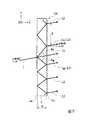
図4は本実施形態に係る画像光拡大部20の構成を示す斜視図である。本説明においては、画像光生成部19の光源部15より単色の光(画像光)が射出されるものとする。 FIG. 4 is a perspective view showing a configuration of the image
図4に示すように、画像光拡大部20は、1つの画像光拡大素子12Aから構成される。画像光拡大素子12Aは、導光板1と、入射側回折格子11と、出射側回折格子12とを有する。 As shown in FIG. 4, the image
導光板1は、ガラスあるいは光学樹脂等の平行平板から構成されている。本実施形態において、導光板1は、屈折率1.52のガラス基板から構成されている。
導光板1は、その一方面に光入射面1aを有し、該光入射面1aに入射側回折格子11が設けられている。また、導光板1は、その他方面に光出射面1bを有し、該光出射面1bに出射側回折格子12が設けられている。The
The
以降の説明においては、適宜、XYZ座標系を用いて説明する。この場合において、X方向は導光板1の光入射面1a及び光出射面1bに平行な面の一方向に対応し、Y方向は光入射面1a及び光出射面1bに平行な面内においてX方向と直交する方向に対応し、Z方向はX方向およびY方向に直交する方向であって導光板1の厚さ方向に対応する。 In the following description, description will be made using the XYZ coordinate system as appropriate. In this case, the X direction corresponds to one direction of the surface parallel to the
入射側回折格子11及び出射側回折格子12は表面レリーフ型回折格子であり、入射側回折格子11と出射側回折格子12とにおいて、格子方向および格子周期が同一となっている。入射側回折格子11は、X方向に延在する格子11aがY方向に複数、等間隔に形成されている。出射側回折格子12は、X方向に延在する格子12aがY方向に複数、等間隔に形成されている。 The incident
本実施形態において、入射側回折格子11及び出射側回折格子12のX方向における格子周期Pxは同一であり、Y方向における格子周期Pyも同一である。なお、PXとPYとは同一であっても良いし、異なっていても良い。具体的に本実施形態において、入射側回折格子11及び出射側回折格子12における格子周期Px及び格子周期Pyは、それぞれ0.447μmに設定される。以下、格子周期Px及び格子周期Pyを総称して格子周期Pと呼ぶこともある。In the present embodiment, the grating period Px in the X direction of the incident
画像光拡大素子12Aに入射した光は入射側回折格子11によって回折されて導光板1内に導入される。本実施形態において、入射側回折格子11は、導光板1内を全反射によって光を伝搬させるように、その回折角が設定される。入射側回折格子11における回折角は、回折格子の格子周期に応じて決まる。 The light incident on the image
本実施形態において、入射側回折格子11及び出射側回折格子12は、凸形状体がXY平面と平行な面内に2次元的に配置された格子パターンを構成している。図4において、d1は入射側回折格子11の凸形状体のZ方向における高さ(以下、格子高さと称する。)を示し、d2は出射側回折格子12の格子高さを示す。 In this embodiment, the incident
続いて、画像光拡大素子12Aにおける瞳拡大機能について説明する。本実施形態において、画像光拡大素子12Aの光入射面1aには、光走査デバイス17により所定の入射角度分布(−10度から+10度の範囲)の光が入射する。 Subsequently, the pupil enlarging function in the image
図5、6は、画像光拡大素子12Aに入射角0度の光が入射した場合の説明図である。なお、図5は導光板1の厚さが0.8mmの場合の説明図であり、図6は導光板1の厚さが0.2mmの場合の説明図である。
図7は、画像光拡大素子12Aに入射角+10度の光が入射した場合の説明図であり、図8は、画像光拡大素子12Aに入射角−10度の光が入射した場合の説明図である。なお、図5乃至8においては、画像光拡大素子12Aに波長0.525μmのレーザー光からなる光Lが入射するものとする。5 and 6 are explanatory diagrams when light having an incident angle of 0 degrees is incident on the image light expansion element 12A. 5 is an explanatory diagram when the thickness of the
FIG. 7 is an explanatory diagram when light having an incident angle of +10 degrees is incident on the image
なお、図5乃至8はYZ平面と平行な断面を示し、Y方向における光の伝播について説明するが、X方向においても同様に光の伝播が生じているものとする。すなわち、画像光拡大素子12Aにより拡大された光は、X方向及びY方向に2次元的に拡大されたものとなる。 5 to 8 show a cross section parallel to the YZ plane, and light propagation in the Y direction will be described. It is assumed that light propagation occurs in the X direction as well. That is, the light expanded by the image
本実施形態においては、回折光のうち、回折効率を高くできる+1次回折光および−1次回折光に注目する。なお、0次回折光も生じるが、光束径の拡大に寄与しないので、0次回折効率は低くすることが好ましい。 In the present embodiment, attention is paid to + 1st order diffracted light and −1st order diffracted light that can increase diffraction efficiency among diffracted lights. Although 0th-order diffracted light is also generated, it does not contribute to the expansion of the beam diameter, so it is preferable to reduce the 0th-order diffraction efficiency.
図5に示すように、光Lは入射側回折格子11によって回折されることで、導光板1の内部に複数の回折光(0次回折光L0、+1次回折光LP1、−1次回折光LM1)を形成する。具体的に、0次回折光L0は、回折角が0度で導光板1内に導入される。+1次回折光LP1及び−1次回折光LM1は、互いの回折角θ1、θ2が等しく、50.6度となる。As shown in FIG. 5, the light L is diffracted by the incident
導光板1内を伝播して出射側回折格子12に到達した光は出射側回折格子12で回折され、その一部(透過回折光)が導光板1から外部に取り出される。 The light that has propagated through the
本実施形態においては、入射側回折格子11及び出射側回折格子12の格子周期Pを同一としている。そのため、入射側回折格子11及び出射側回折格子12は回折力が同じため、出射側回折格子12から射出される際の出射角度も入射角と同じ0度となる。 In the present embodiment, the grating periods P of the incident
出射側回折格子12で反射される+1次回折光LP1及び−1次回折光LM1は、出射側回折格子12に入射した角度と同じ角度、すなわち、回折角と同じ50.6度で反射され、導光板1内を伝播して光入射面1aに到達する。
ここで、出射側回折格子12による反射回折光が到達する位置に入射側回折格子11が配置されていると、回折光が生じて導光板1から光が外に射出されてしまい、導光板1内を伝播する光量が低下してしまう。The + 1st order diffracted light LP1 and the −1st order diffracted light LM1 reflected by the exit
Here, if the incident
本実施形態において、入射側回折格子11は導光板1の光入射面1aの一部(中央部)に設けられ、出射側回折格子12は導光板1の光出射面1bの全面に設けられている。つまり、入射側回折格子11と出射側回折格子12とは導光板1の厚さ方向(Z方向)で重なる領域に形成され、出射側回折格子12の形成領域の大きさは、入射側回折格子11の形成領域の大きさより大きい。 In the present embodiment, the incident
本実施形態では、上述のように、出射側回折格子12による反射回折光が到達する光入射面1aの位置に入射側回折格子11が位置しないため、出射側回折格子12による反射回折光を光入射面1aで全反射させることで導光板1内を良好に伝播させることができる。 In the present embodiment, as described above, since the incident
本実施形態では、+1次回折光LP1及び−1次回折光LM1の回折角(50.6度)が導光板1の屈折率(1.52)で決まる臨界角(41.4度)より大きくなるため、+1次回折光LP1及び−1次回折光LM1を導光板1内で全反射によりY方向に伝播させる。In the present embodiment, + 1st-order diffraction angle of the diffracted lightL P1 and -1 order diffracted lightL M1 (50.6 °) larger than the critical angle (41.4 degrees), which determines the refractive index of the light guide plate 1 (1.52) Therefore, the + 1st order diffracted light LP1 and the −1st order diffracted light LM1 are propagated in the Y direction by total reflection in the
画像光拡大素子12Aは、導光板1内を全反射により伝播する+1次回折光LP1及び−1次回折光LM1を出射側回折格子12によって複数回出射させることで光Lを複製し、複数の出射光L2からなる拡大光線束Kを得る。Image light enlarged
ここで、出射側回折格子12の透過1次回折効率が高いと、出射側回折格子12に対する+1次回折光LP1及び−1次回折光LM1の1回目の入射時に多くの光量が導光板1の外部に射出されてしまい、導光板1内に残る光量が減ってしまう。これにより、導光板1内を伝播する+1次回折光LP1及び−1次回折光LM1における出射側回折格子12に対する2回目以降の入射時に導光板1の外部に射出される光量が大幅に減少してしまう。Here, if the transmission first-order diffraction efficiency of the output-
そのため、出射側回折格子12の回折効率は、入射側回折格子11の回折効率よりも低く設定されている。すなわち、出射側回折格子12の格子高さd2は、入射側回折格子11の格子高さd1よりも低く設定される。なお、出射側回折格子12の回折効率は、出射側回折格子12より導光板1の外部に光を取り出す回数(出射光L2の数)に応じて設定される。 Therefore, the diffraction efficiency of the exit
入射側回折格子11の格子高さd1は、垂直に入射する光L(波長0.525μm)に対して1次回折効率が高くなる高さに設定される。例えば、入射側回折格子11の屈折率が1.65である場合、格子高さd1は約0.25μmとなり、格子高さd2は0.25μmより低く設定される。 The grating height d1 of the incident-
上述のように本実施形態では、入射側回折格子11を光入射面1aの中央に設けることで、+1次回折光LP1及び−1次回折光LM1を導光板1内に伝播させることで光線の複製を行っている。これに対し、入射側回折格子11を光入射面1aの端部に設けた場合、+1次回折光LP1或いは−1次回折光LM1を導光板1の端部から出射させるためには、全反射の回数が多くなることで光の減衰が多くなり、導光板1の端部での出射光線の強度が大きく低下してしまう。
本実施形態によれば、光Lの入射位置から導光板1の端までの距離が導光板1全体の半分で済むため、導光板1の端部での出射光の強度低下を抑制できる。As described above, in the present embodiment, the incident-
According to this embodiment, since the distance from the incident position of the light L to the end of the
ところで、一般に、観察者の眼の瞳孔直径は最小で2mm程度と言われている。
そのため、観察者の眼が上下左右に移動した際に、観察者が画像を視認できるようにするためには、拡大光線束Kを構成する複数の出射光L2の間隔が瞳孔直径(2mm)程度に設定する必要がある。すなわち、本実施形態の画像光拡大素子12Aは、複数の出射光L2の間隔を2mm程度にするように設計されている。Incidentally, it is generally said that the pupil diameter of the observer's eye is about 2 mm at the minimum.
Therefore, in order to allow the observer to visually recognize the image when the observer's eyes move up, down, left, and right, the interval between the plurality of emitted lights L2 constituting the enlarged light bundle K is about the pupil diameter (2 mm). Must be set to That is, the image
画像光拡大素子12Aから外部に取り出される出射光L2の間隔を小さくする手段としては、以下の手法が考えられる。 The following methods are conceivable as means for reducing the interval between the emitted light L2 extracted from the image
第1の手法としては、入射側回折格子11における格子周期Pを大きくする、つまり、回折角を小さくすることが考えられる。しかしながら、この場合、回折角が臨界角より小さくなることで全反射による導光板1内の光の伝播が出来なくなってしまい、瞳拡大機能(出射光線の複製機能)が十分に得られなくなるおそれがある。 As a first method, it is conceivable to increase the grating period P in the incident
また、第2の手法としては、導光板1として屈折率が高い材料を用いることが考えられる。しかしながら、この場合、本実施形態で用いた一般的な光学ガラス(屈折率1.52)よりも屈折率が高いガラスは高価なため、製造コストが上昇してしまう。 As a second method, it is conceivable to use a material having a high refractive index as the
本発明者は、出射光L2の間隔が格子周期P及び導光板1の厚さで規定されることに着目し、導光板1内において全反射条件を満たす回折角を得る格子周期Pに設定した場合において、出射光L2の間隔Dを2mm以下にすることが可能な導光板1の厚さの範囲を見出した。
具体的に、本発明者は、導光板1の厚さAを0.2mm〜0.8mmの範囲に設定することを見出した。The inventor paid attention to the fact that the interval of the outgoing light L2 is defined by the grating period P and the thickness of the
Specifically, the present inventors have found that the thickness A of the
格子周期Pを0.447μm、導光板1の厚さAを0.8mmとした画像光拡大素子12Aにおいて+1次方向及び−1次方向とでそれぞれ3回ずつ出射光L2を取り出すことで、図5に示すように、2mm間隔で複数の出射光L2が配置された、光束径10mmの拡大光線束Kを生成することができる。
この場合、拡大光線束Kが存在する10mmの範囲内で観察者の眼が移動しても、出射光L2の少なくとも1本が瞳孔に入射するので、画像を観察者に良好に視認させることができる。By extracting the emitted light L2 three times each in the + 1st order direction and the −1st order direction in the image
In this case, even if the observer's eye moves within the range of 10 mm where the magnifying light bundle K exists, at least one of the emitted light L2 enters the pupil, so that the image can be viewed well by the observer. it can.
また、格子周期Pを0.447μm、導光板1の厚さAを0.2mmとした画像光拡大素子12Aにおいて+1次方向及び−1次方向とでそれぞれ11回ずつ出射光L2を取り出すことで、図6に示すように、0.5mmの間隔D1で複数の出射光L2が配置された、光束径10mmの拡大光線束Kを生成することができる。
ここで、光L及び各出射光L2は直径1mm程度のガウス分布Gを有している。そのため、隣り合う出射光L2の間隔D1が0.5mmとなると、図6に示すように、各出射光L2は空間的に重なり合った状態となる。Further, by extracting the emitted
Here, the light L and each outgoing light L2 have a Gaussian distribution G having a diameter of about 1 mm. Therefore, when the distance D1 of the exit adjacent light L2 is 0.5 mm, as shown in FIG. 6, the output light L2 is in a state of overlapping spatially.
この場合、拡大光線束Kが存在する10mmの範囲内で観察者の眼が移動したとしても、出射光L2の少なくとも4本が瞳孔に入射するので、観察者に画像を良好に視認させることができる。
また、図6に示すように、各出射光L2が空間的に重なり合うため、拡大光線束Kの範囲内で観察者の眼が移動したとしても、眼に均一な照度分布の光を入射させることができる。よって、観察者は、明るさムラの小さい良質な画像を視認することができる。In this case, even if the observer's eye moves within the range of 10 mm where the magnifying light bundle K exists, at least four of the emitted lights L2 are incident on the pupil, so that the observer can see the image well. it can.
Further, as shown in FIG. 6, since the emitted lights L2 are spatially overlapped, even if the observer's eyes move within the range of the expanded light bundle K, light having a uniform illuminance distribution is incident on the eyes. Can do. Therefore, the observer can visually recognize a high-quality image with small brightness unevenness.
続いて、導光板1の厚さAが0.2mm〜0.8mmの範囲から外れた場合について説明する。例えば、導光板1の厚さAが0.8mmよりも大きくなった場合、出射光L2の間隔が2mmよりも大きくなってしまい、瞳拡大機能が不十分となってしまう。 Then, the case where the thickness A of the light-
導光板1の厚さAが0.2mmよりも小さくなった場合、導光板1の端部から出射されるまでの出射光L2における反射回数が多くなってしまい、導光板1の端部における出射光L2の出射強度が大幅に低下してしまう。よって、導光板1の中央部と端部とにおいて、出射光L2の強度にムラが生じてしまい、観察者の眼が移動した際に、視認画像に明るさムラが生じるおそれがある。厚さが0.2mmよりも小さくなると、導光板1が破損し易くなってしまい、取り扱いが難しくなる。 When the thickness A of the
本実施形態の画像光拡大素子12Aによれば、厚さ0.2mm〜0.8mmの導光板1を用いることで、観察者の眼が移動しても画像を良好に視認させることができる。 According to the image
続いて、画像光拡大素子12Aに光Lが傾いて入射する場合(入射角が±10度の場合)について図7,8を参照しつつ説明する。なお、図7,8においては、光入射面1a或いは光出射面1bに対する反時計回りの角度の符号を正(+)とし、時計回りの角度を負(−)とした。 Next, the case where the light L is incident on the image
図7に示すように、光Lの入射角が10度の場合、入射側回折格子11による+1次回折光LP1及び−1次回折光LM1の回折角は異なる。具体的に、+1次回折角θPは+62.4度、−1次回折角θMは−41.4度となる。また、導光板1からの+1次回折角θP及び−1次回折角θMの出射角度は、入射角と同じ+10度、つまり同一方向に射出される。As shown in FIG. 7, when the angle of incidence of the light L is 10 degrees, the diffraction angle of the + 1st by incident-
+10度の入射角で入射する光Lにおいて回折角が小さくなるのは、−1次回折光LM1の方である。従って、−1次回折光LM1の回折角θMの絶対値が臨界角41.4度より大きければ、+1次回折光LP1の回折角θPは臨界角より必ず大きくなる。In the light L incident at an incident angle of +10 degrees, the diffraction angle becomes smaller in the −1st order diffracted light LM1 . Therefore, the absolute value of the diffraction angle thetaM -1 order diffracted lightL M1 is greater than the critical angle 41.4 degrees, the diffraction angle thetaP of + 1st-order diffracted lightL P1 becomes necessarily larger than the critical angle.
本実施形態において、回折角θMの絶対値が臨界角と等しいため、+1次回折光LP1及び−1次回折光LM1は導光板1内を全反射で伝播することができる。なお、本実施形態では、入射角が10度よりも大きくなると、−1次回折光LM1の回折角θMは臨界角より小さくなり、−1次回折光LM1は導光板1内を全反射により伝播できなくなってしまう。In the present embodiment, since the absolute value of the diffraction angle θM is equal to the critical angle, the + 1st order diffracted light LP1 and the −1st order diffracted light LM1 can propagate through the
また、図8に示すように、光Lの入射角が−10度の場合、図7の入射角10度の関係を上下反転させた状態となる。つまり、+1次回折角θPは+41.4度、−1次回折角θMは−62.4度となる。また、導光板1からの+1次回折角θP及び−1次回折角θMの出射角度は、入射角と同じ−10度、つまり同一方向に射出される。
−10度の入射角で入射する光Lにおいて回折角が小さい+1次回折光LP1の回折角θPは臨界角と等しいため、+1次回折光LP1及び−1次回折光LM1は導光板1内を全反射で伝播することができる。As shown in FIG. 8, when the incident angle of the light L is −10 degrees, the relationship of the incident angle of 10 degrees in FIG. That is, + 1-order diffraction angle thetaP is Tasu41.4 °, -1 order diffraction thetaM becomes -62.4 degrees. Also, +1 emission angle of order diffraction angle thetaP and -1 order diffraction thetaM from the
Since the diffraction angle thetaP of + 1st-order diffraction angle is less diffracted lightL P1 in the light L incident at an incident angle of -10 degrees equal to the critical angle, + 1st-order diffracted lightL P1 and -1 order diffracted lightL M1 is the
ここで、1次回折光が導光板1内を全反射により伝播できる条件を式で説明する。まず、光Lの波長をλとし、入射角の最大角度の絶対値を|θmax|とし、導光板1の屈折率をnとし、導光板1内での1次回折光の回折角が臨界角と一致する格子周期Pは、以下の式で表される。Here, the conditions under which the first-order diffracted light can propagate through the
P=λ/[sin|θmax|+1]・・式(1) P = λ / [sin | θmax | +1] (1)
なお、格子周期Pを一定とした場合、回折角は入射する光Lの波長に依存し、波長が短い程、回折角が小さくなる。従って、入射する光Lが波長分布を持っている場合、光Lの波長帯域の一番短い波長λminに対する1次回折光の回折角の絶対値が臨界角より大きければ、全ての波長帯の光Lについて1次回折光を導光板1内で全反射により伝播させることができる。この条件を満たす、格子周期Pは、以下の式で表される。なお、下式の格子周期Pとは、格子周期Px及びPYのうち周期が異なる場合、周期が大きいものが対象となる。When the grating period P is constant, the diffraction angle depends on the wavelength of the incident light L, and the shorter the wavelength, the smaller the diffraction angle. Therefore, when the incident light L has a wavelength distribution, if the absolute value of the diffraction angle of the first-order diffracted light with respect to the shortest wavelength λmin of the wavelength band of the light L is larger than the critical angle, the light in all wavelength bands For L, the first-order diffracted light can be propagated in the
P=λmin/[sin|θmax|+1]・・式(2)P = λmin / [sin | θmax | +1] (2)
本実施形態の画像光拡大素子12Aによれば、画像光拡大素子12Aに光Lが傾いて入射する場合においても、厚さ0.2mm〜0.8mmの導光板1を用いることで、観察者の眼が移動しても画像を良好に視認させることが可能である。 According to the image
図3に戻って、集光光学系13は複数のレンズ(不図示)から構成され、全体として正のパワーを有する。画像光拡大素子12Aから射出される拡大光線束Kは一本の細いビームではなく空間的に拡がっている。そのため、直接的に接眼光学系14に入射させると、該接眼光学系14によって収差や像の歪みが生じてしまう。これに対し、本実施形態では、全体として正のパワーを有する集光光学系13によって画像光拡大素子12Aから射出された光を集光させ、接眼光学系14の手前に中間像GMを形成している。これにより、上記収差や像の歪みの発生を低減することができる。 Returning to FIG. 3, the condensing
接眼光学系14は、少なくともメインフレーム120(図2参照)と観察者Mの眼MEを含む面内において、正のパワーを有するハーフミラー(凹面鏡)或いはホログラフィック光学素子から構成される。接眼光学系14は、中間像GMを形成した光を平行化して観察者Mの眼MEの瞳孔近傍に射出瞳を形成するとともに外光の一部を透過させる。そのため、観察者Mは外光とともに遠方に虚像G1を視認することができる。 The eyepiece
以上述べたように、本実施形態の画像光拡大素子12Aによれば、観察者Mの眼MEに、画像光として、複数の出射光L2が瞳孔のサイズよりも小さい2mm程度で配置された拡大光線束Kを入射させることができる。よって、観察者Mが眼MEを移動させた場合でも、眼MEに画像光を良好に視認させることができる。また、1次回折光が導光板1内を全反射の状態で伝播して出射側回折格子12から出射させるため、光の利用効率が高いものとなる。
したがって、該画像光拡大素子12Aを備えたHMD300によれば、画像視認性に優れた信頼性の高いものとなる。As described above, according to the image
Therefore, according to the
(第2実施形態)
続いて、本発明の第2実施形態について説明する。本実施形態と上記実施形態との違いは、画像光拡大素子の構成である。具体的に、上記実施形態では、画像光生成部19の光源部15より単色の光が入射する場合について説明したが、本実施形態では画像光生成部19の光源部15より3色の光が入射する場合について説明する。(Second Embodiment)
Subsequently, a second embodiment of the present invention will be described. The difference between this embodiment and the above embodiment is the configuration of the image light enlarging element. Specifically, in the above embodiment, the case where monochromatic light is incident from the
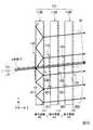
図9乃至11は本実施形態に係る画像光拡大部の構成を示す断面図である。なお、図9乃至11はYZ平面と平行な断面を示し、Y方向における光の伝播について説明するが、X方向においても同様に光の伝播が生じているものとする。すなわち、画像光拡大部により拡大された光は、X方向及びY方向に2次元的に拡大されたものとなる。 9 to 11 are cross-sectional views illustrating the configuration of the image light enlargement unit according to the present embodiment. 9 to 11 show cross sections parallel to the YZ plane, and light propagation in the Y direction will be described. It is assumed that light propagation occurs in the X direction as well. That is, the light expanded by the image light expansion unit is two-dimensionally expanded in the X direction and the Y direction.
図9は、青色用画像光拡大素子112Bにおける回折機能の説明図であり、図10は、緑色用画像光拡大素子112Gにおける回折機能の説明図であり、図11は、赤色用画像光拡大素子112Rにおける回折機能の説明図である。 9 is an explanatory diagram of a diffraction function in the blue image
図9乃至11に示すように、本実施形態の画像光拡大部112は、青色用画像光拡大素子(第1画像光拡大素子)112B、緑色用画像光拡大素子(第2画像光拡大素子)112G、及び赤色用画像光拡大素子(第3画像光拡大素子)112Rを含む。 As shown in FIGS. 9 to 11, the image
青色用画像光拡大素子112B、緑色用画像光拡大素子112G及び赤色用画像光拡大素子112Rの基本構成は、上記実施形態の画像光拡大素子12Aと同一であることから、共通する部分には同一の符号を付してそれらの説明を省略する。 Since the basic configuration of the blue image
本実施形態において、画像光拡大部112は、画像光の入射側から出射側に向かって、青色用画像光拡大素子112B、緑色用画像光拡大素子112G、赤色用画像光拡大素子112R(以下、これらを総称して単に拡大素子112B,112G,112Rと称する。)が光Lの進行方向に沿って順に配置されている。すなわち、各拡大素子112B,112G,112Rは、対応する光の波長が短いものから長いものの順に配置されている。また、拡大素子112B,112G,112Rは、同一の厚さの導光板1から構成されている。 In the present embodiment, the image
本実施形態において、画像光生成部19の光源部15より射出される画像光(光L)は、青色光(第1の波長帯の光)LB、緑色光(第2の波長帯の光)LG及び赤色光(第3の波長帯の光)LRを含む。これら青色光LB、緑色光LG、および赤色光LRは、同じ入射角(±10度の範囲)で画像光拡大部112に入射する。 In the present embodiment, the image light (light L) emitted from the
本実施形態において、青色用画像光拡大素子112Bは、導光板1Bと、入射側回折格子11Bと、出射側回折格子12Bとを有し、波長0.460μmの青色光LBに対応する。
緑色用画像光拡大素子112Gは、導光板1Gと入射側回折格子11Gと出射側回折格子12Gとを有し、波長0.525μmの緑色光LGに対応する。
赤色用画像光拡大素子112Rは、導光板1Rと入射側回折格子11Rと出射側回折格子12Rとを有し、波長0.610μmの赤色光LRに対応する。In the present embodiment, the blue image
The green image
The red image
本実施形態において、青色用画像光拡大素子112B、緑色用画像光拡大素子112G及び赤色用画像光拡大素子112Rの格子周期PB,PG,PRは、以下の関係を満たしている。つまり、画像光生成部19から離間するにつれて、格子周期PB,PG,PRが大きくなっている。
PB<PG<PRIn the present embodiment, the grating periods PB, PG, and PR of the blue image
PB <PG <PR
また、入射側回折格子11Bの格子高さH11、出射側回折格子12Bの格子高さH12、入射側回折格子11Gの格子高さH21、出射側回折格子12Gの格子高さH22、入射側回折格子11Rの格子高さH31、出射側回折格子12Rの格子高さH32は、以下の関係を満たしている。 Also, the grating height H11 of the incident
H11<H21<H31
H12<H11
H22<H21
H32<H31
H12<H11<H22<H21<H32<H31H11 <H21 <H31
H12 <H11
H22 <H21
H32 <H31
H12 <H11 <H22 <H21 <H32 <H31
まず、青色用画像光拡大素子112Bについて説明する。
図9に示したように、青色用画像光拡大素子112Bは、青色光LBに対する+1次回折光及び−1次回折光のいずれも導光板1B(屈折率1.52)の臨界角より大きな角度で回折させ、導光板1B内において回折光が伝播するように回折格子の格子周期Pが決められている。具体的に、本実施形態において、入射側回折格子11B及び出射側回折格子12Bにおける格子周期PB(格子周期Px及び格子周期Py)は、0.392μmに設定されている。First, the blue image
As shown in FIG. 9, the blue image
ここで、比較例として、画像光の入射側から出射側に向かって、拡大素子112R,112G,112Bの順(格子周期が小さくなる順)に配置されていた場合について説明する。この場合、拡大素子112Rの格子周期が最も大きくなるため、例えば、青色光LBが入射すると、その回折角が小さくなってしまい、後段に配置される拡大素子112G,112Bに入射することで不要な回折光の成分が多数発生し、入射角と異なる角度で出射される成分の光が増加してしまう。 Here, as a comparative example, a case will be described in which the
これに対し、本実施形態では、上述のように画像光の入射側から出射側に向かって、拡大素子112B,112G,112Rの順(格子周期が大きくなる順)に配置されている。青色用画像光拡大素子112Bには緑色光LG及び赤色光LRも入射するが、緑色光LG及び赤色光LRは青色光LBよりも波長が長いため、青色光LBよりも大きな角度で回折される。よって、青色用画像光拡大素子112Bの後段に配置される緑色用画像光拡大素子112G或いは赤色用画像光拡大素子112Rに所定の入射角と異なる角度の光が入射することが抑制されるので、不要な回折光の発生を抑制することができる。 On the other hand, in this embodiment, as described above, the magnifying
また、入射側回折格子11Bの高さH11は、波長0.460μmの青色光LBに対して1次回折効率が高く、緑色光LG及び赤色光LRに対する回折効率が低くなる高さに設定される。 The height H11 of the incident
具体的に入射側回折格子11Bの高さH11は、該入射側回折格子11Bの屈折率が1.65の場合、0.57μmとなる。一方、出射側回折格子12Bの高さH12は、0.57μmよりも低くなる。これにより、出射側回折格子12Bから出射される光量分布を適正化することができる。 Specifically, the height H11 of the incident
青色用画像光拡大素子112Bにおいて、入射側回折格子11B及び出射側回折格子12Bは格子周期が等しいので、導光板1内を全反射により伝播して出射側回折格子12Bに到達した光線は、入射角と同じ角度で出射される。したがって、上記第1実施形態の画像光拡大素子12Aと同様、青色用画像光拡大素子112Bは、入射角と同じ角度で出射される複数の青色光LB2を生成する。すなわち、入射角と同一角度で出射される光を複製した拡大光線束を生成する。 In the blue image
複数の青色光LB2は、緑色用画像光拡大素子112G及び赤色用画像光拡大素子112Rに入射した際に回折され、不要な回折光を生じる。この不要な回折光の回折角が10度より十分大きければ後段で遮蔽或いは吸収可能である。
緑色用画像光拡大素子112G或いは赤色用画像光拡大素子112Rは、緑色光LG或いは赤色光LRに対する回折効率が高くなるように格子高さが設定されるため、青色光LB2に対する回折効率は低く、上記不要な回折光の発生は実質的に抑制される。The plurality of blue lights LB2 are diffracted when incident on the green image light expanding
The grating height of the green image light expanding
次に、緑色用画像光拡大素子112Gについて説明する。
図10に示したように、緑色用画像光拡大素子112Gは、緑色光LGに対する+1次回折光及び−1次回折光のいずれも導光板1G(屈折率1.52)の臨界角より大きな角度で回折させ、導光板1G内において回折光が伝播するように回折格子の格子周期が決められている。
具体的に、本実施形態において、入射側回折格子11G及び出射側回折格子12Gにおける格子周期PG(格子周期Px及び格子周期Py)は0.447μmに設定されている。Next, the green image
As shown in FIG. 10, the green image light expanding
Specifically, in the present embodiment, the grating period PG (grating period Px and grating period Py) in the incident
緑色用画像光拡大素子112Gに入射した赤色光LRは、緑色光LGよりも波長が長いため、緑色光LGよりも大きな角度で回折される。そのため、緑色用画像光拡大素子112Gの後段に配置される赤色用画像光拡大素子112Rにおいて不要な回折光を発生させることが抑制される。 Since the red light LR that has entered the green image
また、入射側回折格子11Gの高さH21は、波長0.525μmの緑色光LGに対して1次回折効率が高く、青色光LB及び赤色光LRに対する回折効率が低くなる高さに設定される。 Further, the height H21 of the incident
具体的に入射側回折格子11Gの高さH21は、該入射側回折格子11Gの屈折率が1.65の場合、0.60μmとなる。一方、出射側回折格子12Gの高さd2は、0.60μmよりも低くなる。これにより、出射側回折格子12Gから出射される光量分布を適正化することができる。 Specifically, the height H21 of the incident
緑色用画像光拡大素子112Gにおいて、入射側回折格子11G及び出射側回折格子12Gの格子周期Pが等しい。そのため、導光板1G内を全反射により伝播して出射側回折格子12Gに到達した光線は、入射角と同じ角度で出射される。
したがって、緑色用画像光拡大素子112Gは、入射角と同じ角度で出射される複数の緑色光LG2を複製する。すなわち、入射角と同一角度で出射される光を複製した拡大光線束を生成する。In the green image
Therefore, the green image
複数の緑色光LG2は、赤色用画像光拡大素子112Rに入射した際に回折され、不要な回折光を生じる。この不要な回折光の回折角が10度より十分大きければ後段で遮蔽或いは吸収可能である。
赤色用画像光拡大素子112Rは、赤色光LRに対する回折効率が高くなるように格子高さが設定されるため、緑色光LG2に対する回折効率は低く、上記不要な回折光の発生は実質的に抑制される。The plurality of green lights LG2 are diffracted when entering the red image light enlarging
Since the red image
次に、赤色用画像光拡大素子112Rについて説明する。
図11に示したように、赤色用画像光拡大素子112Rは、赤色光LRに対する+1次回折光及び−1次回折光のいずれも導光板1R(屈折率1.52)の臨界角より大きな角度で回折させ、導光板1R内において回折光がY方向及びY方向に伝播するように回折格子の格子周期が決められている。
具体的に、本実施形態において、入射側回折格子11R及び出射側回折格子12Rにおける格子周期PR(格子周期Px及び格子周期Py)は0.520μmに設定されている。Next, the red image
As shown in FIG. 11, the image light enlarging element for red 112R diffracts both the + 1st order diffracted light and the −1st order diffracted light with respect to the red light LR at an angle larger than the critical angle of the
Specifically, in this embodiment, the grating period PR (grating period Px and grating period Py) in the incident
入射側回折格子11Rの高さH31は、波長0.610μmの赤色光LRに対して1次回折効率が高く、青色光LB及び緑色光LGに対する回折効率が低くなる高さに設定される。具体的に入射側回折格子11Rの高さH31は、該入射側回折格子11Rの屈折率が1.65の場合、0.70μmとなる。一方、出射側回折格子12Rの高さH32は、0.70μmよりも低くなる。これにより、出射側回折格子12Rから出射される光量分布を適正化することができる。 The height H31 of the incident-
赤色用画像光拡大素子112Rにおいて、入射側回折格子11R及び出射側回折格子12Rの格子周期が等しいので、導光板1R内を全反射により伝播して出射側回折格子12Rに到達した光線は、入射角と同じ角度で出射される。
したがって、赤色用画像光拡大素子112Rは、入射角と同じ角度で出射される複数の赤色光LR2を複製する。In the red image light expanding
Therefore, the red image
本実施形態によれば、拡大素子112B,112G,112Rの格子周期を上述のように色毎に異ならせることにより、各拡大素子112B,112G,112Rでの回折角を同じにすることができる。
また、本実施形態において、拡大素子112B,112G,112R(導光板1B,1G,1R)の厚さが同一であるため、各色の出射光(青色光LB2、緑色光LG2及び赤色光LR2)の出射位置が同一となる。According to the present embodiment, the diffraction period of each of the
In the present embodiment, since the
具体的に、拡大素子112B,112G,112Rを構成する導光板1B,1G,1Rの厚さを0.8mmとした場合、拡大素子112B,112G,112Rを透過することで光束径10mmの拡大光線束K1が生成される。拡大光線束K1は、各色の出射光(青色光LB2、緑色光LG2及び赤色光LR2)の間隔が上記第1実施形態と同様に約2mmとなる。 Specifically, when the thickness of the
ここで、本実施形態の構成の比較例として、拡大素子112B,112G,112Rの格子周期を同一とし、導光板1B,1G,1Rの厚さを異ならせることで各色光の出射位置を同一にすることも考えられる。具体的に、回折角が小さい導光板1B,1G,1Rの厚さを厚くする。 Here, as a comparative example of the configuration of the present embodiment, the
しかしながら、この場合、格子周期が各色光で同一となるため、各色光において回折角が異なることで回折効率も異なってしまう。特に回折角が大きくなる赤色光LRの回折効率が低下し、各色光の色バランスを調整することが難しくなってしまう。 However, in this case, since the grating period is the same for each color light, the diffraction efficiency varies depending on the diffraction angle for each color light. In particular, the diffraction efficiency of the red light LR with a large diffraction angle decreases, and it becomes difficult to adjust the color balance of each color light.
これに対し、本実施形態の構成によれば、各色光において回折角が同じになるように格子周期を決めるので、各色光の回折効率もそれぞれ同程度になり、色バランスを取り易くなるといった効果が得られる。
また、導光板1B,1G,1Rの厚さが同一となるため、回折格子を同一のプロセスで作成可能となるので、各拡大素子112R,112G,112Bの製造コストを抑えることができるといった効果が得られる。On the other hand, according to the configuration of the present embodiment, the grating period is determined so that the diffraction angles are the same for each color light, so that the diffraction efficiency of each color light is also the same and the color balance is easily achieved. Is obtained.
In addition, since the thicknesses of the
以上述べたように、本実施形態の画像光拡大部112によれば、観察者Mの眼MEに対して、各色の出射光(青色光LB2、緑色光LG2及び赤色光LR2)の間隔が瞳孔のサイズよりも小さい2mm程度で配置された画像光(拡大光線束K1)を入射させることができる。よって、観察者Mが眼MEを移動させた場合でも、眼MEに3色の画像光を視認させることができる。また、各色光の出射位置が同一のため、観察者Mが眼MEを移動させた場合でも、観察者Mに視認される画像光の色バランスの乱れが抑制される。
したがって、この画像光拡大部112を備えた本実施形態のHMDによれば、観察者の眼の移動によらず、カラー画像の視認性に優れた信頼性の高い画像表示装置を提供することができる。As described above, according to the image
Therefore, according to the HMD of this embodiment including the image
なお、本発明の技術範囲は上記実施形態に限定されるものではなく、本発明の趣旨を逸脱しない範囲において種々の変更を加えることが可能である。
上記実施形態では、光Lの入射角を±10度とする場合を例に挙げたが、光Lの入射角の範囲は±10度に限定されることはない。
例えば、±10度以上の入射角で光Lを入射させるようにしてもよい。この場合、導光板1内において全反射条件を満たすように格子周期P、導光板1の厚さを0.2mm〜0.8mmの範囲で適宜設定すればよい。The technical scope of the present invention is not limited to the above embodiment, and various modifications can be made without departing from the spirit of the present invention.
In the above embodiment, the case where the incident angle of the light L is set to ± 10 degrees has been described as an example, but the range of the incident angle of the light L is not limited to ± 10 degrees.
For example, the light L may be incident at an incident angle of ± 10 degrees or more. In this case, what is necessary is just to set suitably the grating period P and the thickness of the light-
1,1R,1G,1B…導光板、1a…光入射面、1b…光出射面、11,11R,11G,11B…入射側回折格子、12,12R,12G,12B…出射側回折格子、12A,112…画像光拡大素子、14…接眼光学系、19…画像光生成部、112R…赤色用画像光拡大素子、112G…緑色用画像光拡大素子、112B…青色用画像光拡大素子、d1,d2,H11,H12,H21,H22,H31,H32…格子高さ、P,PB,PG,PR…格子周期、LM1…−1次回折光、LP1…+1次回折光。1, 1R, 1G, 1B ... light guide plate, 1a ... light incident surface, 1b ... light exit surface, 11, 11R, 11G, 11B ... incident side diffraction grating, 12, 12R, 12G, 12B ... output side diffraction grating,
Claims (9)
Translated fromJapanese前記光入射面に設けられた入射側回折格子と、
前記光出射面に設けられ、前記入射側回折格子と同じ格子周期となるように設けられた出射側回折格子と、を備え、
前記入射側回折格子は、前記出射側回折格子よりも小さく、
前記入射側回折格子の格子周期は、前記入射側回折格子で回折した+1次回折光及び−1次回折光の前記導光板内における回折角のうち小さい方の回折角が、前記導光板の臨界角よりも大きくなる周期であることを特徴とする光束径拡大素子。A light guide plate having a light incident surface and a light exit surface, and having a thickness of 0.2 mm to 0.8 mm;
An incident-side diffraction grating provided on the light incident surface;
An exit side diffraction grating provided on the light exit surface and provided to have the same grating period as the entrance side diffraction grating;
The incident side diffraction grating is smaller than the output side diffraction grating,
The grating period of the incident side diffraction grating is such that the smaller diffraction angle of the + 1st order diffracted light and −1st order diffracted light diffracted by the incident side diffraction grating in the light guide plate is larger than the critical angle of the light guide plate. The light beam diameter enlarging element is characterized in that the period becomes larger.
前記光入射面の格子周期が、
P ≦ λmin/(sin|θmax|+1)
を満たすことを特徴とする請求項1に記載の光束径拡大素子。The shortest wavelength in the wavelength band of incident light incident on the light incident surface is λmin , the absolute value of the maximum angle of incidence of the incident light with respect to the light incident surface is | θmax |, and the light incident surface When the lattice period of P is P,
The grating period of the light incident surface is
P ≦ λmin / (sin | θmax | +1)
The light beam diameter enlarging element according to claim 1, wherein:
請求項1乃至3のいずれか一項に記載の光束径拡大素子から構成される、画像光拡大素子と、を備えることを特徴とする画像表示装置。An image light generator for emitting image light;
An image display device comprising: an image light enlarging element comprising the light beam diameter enlarging element according to claim 1.
前記画像光拡大素子を複数備えており、
前記複数の画像光拡大素子の各々の前記入射側回折格子の格子周期が互いに異なる周期であることを特徴とする請求項4に記載の画像表示装置。The image light includes light of different wavelength bands,
A plurality of the image light enlarging elements,
The image display apparatus according to claim 4, wherein grating periods of the incident-side diffraction gratings of the plurality of image light expanding elements are different from each other.
前記第1画像光拡大素子、前記第2画像光拡大素子及び前記第3画像光拡大素子の各々の前記入射側回折格子の格子周期は、各々の前記入射側回折格子で回折した回折光の回折角が同じ角度となるような周期であり、
前記画像光は、前記第1画像光拡大素子に対応する第1波長帯の光、前記第2画像光拡大素子に対応する第2波長帯の光及び前記第3画像光拡大素子に対応する第3波長帯の光を含むことを特徴とする請求項5乃至7のいずれか一項に記載の画像表示装置。The plurality of image light expansion elements include a first image light expansion element, a second image light expansion element, and a third image light expansion element,
The grating period of the incident-side diffraction grating of each of the first image light expanding element, the second image light expanding element, and the third image light expanding element is the number of diffraction lights diffracted by each incident-side diffraction grating. The cycle is such that the folding angle is the same angle,
The image light includes light in a first wavelength band corresponding to the first image light expansion element, light in a second wavelength band corresponding to the second image light expansion element, and first light corresponding to the third image light expansion element. The image display device according to claim 5, comprising light in a three-wavelength band.
前記接眼光学系は、光透過性を有することを特徴とする請求項4乃至7のいずれか一項に記載の画像表示装置。An eyepiece optical system on which the light emitted from the plurality of image light expansion elements is incident;
The image display apparatus according to claim 4, wherein the eyepiece optical system is light transmissive.
Priority Applications (5)
| Application Number | Priority Date | Filing Date | Title |
|---|---|---|---|
| JP2016036787AJP6736911B2 (en) | 2016-02-29 | 2016-02-29 | Luminous flux diameter expanding element and image display device |
| US15/433,618US10281725B2 (en) | 2016-02-29 | 2017-02-15 | Light flux diameter expanding element and image display device |
| US16/367,985US10989925B2 (en) | 2016-02-29 | 2019-03-28 | Light flux diameter expanding element and image display device |
| US17/197,249US11619818B2 (en) | 2016-02-29 | 2021-03-10 | Light flux diameter expanding element and image display device |
| US18/110,181US12222509B2 (en) | 2016-02-29 | 2023-02-15 | Light flux diameter expanding element and image display device |
Applications Claiming Priority (1)
| Application Number | Priority Date | Filing Date | Title |
|---|---|---|---|
| JP2016036787AJP6736911B2 (en) | 2016-02-29 | 2016-02-29 | Luminous flux diameter expanding element and image display device |
Publications (2)
| Publication Number | Publication Date |
|---|---|
| JP2017156388Atrue JP2017156388A (en) | 2017-09-07 |
| JP6736911B2 JP6736911B2 (en) | 2020-08-05 |
Family
ID=59679818
Family Applications (1)
| Application Number | Title | Priority Date | Filing Date |
|---|---|---|---|
| JP2016036787AActiveJP6736911B2 (en) | 2016-02-29 | 2016-02-29 | Luminous flux diameter expanding element and image display device |
Country Status (2)
| Country | Link |
|---|---|
| US (4) | US10281725B2 (en) |
| JP (1) | JP6736911B2 (en) |
Cited By (12)
| Publication number | Priority date | Publication date | Assignee | Title |
|---|---|---|---|---|
| KR20190029489A (en)* | 2017-09-12 | 2019-03-20 | 주식회사 엘지화학 | Diffraction light guide plate and manufacturing method for diffraction light guide plate |
| KR20190045865A (en)* | 2017-10-24 | 2019-05-03 | 주식회사 엘지화학 | Diffraction light guide plate and manufacturing method for diffraction light guide plate |
| WO2020255482A1 (en)* | 2019-06-21 | 2020-12-24 | 株式会社日立エルジーデータストレージ | Light guide plate, production method for same, light guide plate module, and image display device |
| JP2021508080A (en)* | 2017-12-22 | 2021-02-25 | ディスペリックス オサケ ユキチュア | Interference-free waveguide display |
| WO2021140716A1 (en)* | 2020-01-10 | 2021-07-15 | 株式会社日立エルジーデータストレージ | Image display element, image display device, and image display method |
| WO2021140717A1 (en)* | 2020-01-10 | 2021-07-15 | 株式会社日立エルジーデータストレージ | Image display element and device |
| CN113544575A (en)* | 2019-03-13 | 2021-10-22 | 株式会社Lg化学 | Diffractive light guide plate |
| JP2021532420A (en)* | 2019-04-25 | 2021-11-25 | エルジー・ケム・リミテッド | Diffraction light guide plate and manufacturing method of diffraction light guide plate |
| WO2022039208A1 (en)* | 2020-08-20 | 2022-02-24 | 凸版印刷株式会社 | Diffraction sheet, method for manufacturing same, three-dimensional display device, light-beam reproduction device, three-dimensional space display system, light-beam reproduction method, and program |
| JP2022035032A (en)* | 2020-08-20 | 2022-03-04 | 凸版印刷株式会社 | Diffractive sheet and manufacturing method, and 3D display device |
| JP2023500583A (en)* | 2019-11-12 | 2023-01-10 | メタ プラットフォームズ テクノロジーズ, リミテッド ライアビリティ カンパニー | High index waveguide for image transmission using low period outcoupling gratings |
| JP2023168438A (en)* | 2019-10-08 | 2023-11-24 | マジック リープ, インコーポレイテッド | Color-selective waveguides for augmented reality/mixed reality applications |
Families Citing this family (36)
| Publication number | Priority date | Publication date | Assignee | Title |
|---|---|---|---|---|
| US11726332B2 (en) | 2009-04-27 | 2023-08-15 | Digilens Inc. | Diffractive projection apparatus |
| WO2016020630A2 (en) | 2014-08-08 | 2016-02-11 | Milan Momcilo Popovich | Waveguide laser illuminator incorporating a despeckler |
| US9933684B2 (en) | 2012-11-16 | 2018-04-03 | Rockwell Collins, Inc. | Transparent waveguide display providing upper and lower fields of view having a specific light output aperture configuration |
| WO2016042283A1 (en) | 2014-09-19 | 2016-03-24 | Milan Momcilo Popovich | Method and apparatus for generating input images for holographic waveguide displays |
| WO2016113534A1 (en) | 2015-01-12 | 2016-07-21 | Milan Momcilo Popovich | Environmentally isolated waveguide display |
| US9632226B2 (en) | 2015-02-12 | 2017-04-25 | Digilens Inc. | Waveguide grating device |
| CN113759555B (en) | 2015-10-05 | 2024-09-20 | 迪吉伦斯公司 | Waveguide Display |
| JP6736911B2 (en)* | 2016-02-29 | 2020-08-05 | セイコーエプソン株式会社 | Luminous flux diameter expanding element and image display device |
| WO2018102834A2 (en) | 2016-12-02 | 2018-06-07 | Digilens, Inc. | Waveguide device with uniform output illumination |
| US10545346B2 (en) | 2017-01-05 | 2020-01-28 | Digilens Inc. | Wearable heads up displays |
| KR102375975B1 (en)* | 2017-04-28 | 2022-03-17 | 삼성디스플레이 주식회사 | Display device, organic light emitting display device and head mount display device |
| EP3635456A4 (en) | 2017-06-13 | 2021-01-13 | Vuzix Corporation | IMAGE LIGHT GUIDE WITH OVERLAPPING GRIDS WITH EXTENDED LIGHT DISTRIBUTION |
| US10732569B2 (en) | 2018-01-08 | 2020-08-04 | Digilens Inc. | Systems and methods for high-throughput recording of holographic gratings in waveguide cells |
| EP3710894B1 (en) | 2018-01-08 | 2025-07-30 | Digilens Inc. | Methods for fabricating optical waveguides |
| CN112041727B (en)* | 2018-04-20 | 2022-11-04 | 3M创新有限公司 | Headset and head mounted display |
| US12034015B2 (en) | 2018-05-25 | 2024-07-09 | Meta Platforms Technologies, Llc | Programmable pixel array |
| US11888002B2 (en) | 2018-12-17 | 2024-01-30 | Meta Platforms Technologies, Llc | Dynamically programmable image sensor |
| US11962928B2 (en) | 2018-12-17 | 2024-04-16 | Meta Platforms Technologies, Llc | Programmable pixel array |
| JP2020106636A (en)* | 2018-12-27 | 2020-07-09 | セイコーエプソン株式会社 | Head mounted display |
| US20200225471A1 (en) | 2019-01-14 | 2020-07-16 | Digilens Inc. | Holographic Waveguide Display with Light Control Layer |
| US20200247017A1 (en) | 2019-02-05 | 2020-08-06 | Digilens Inc. | Methods for Compensating for Optical Surface Nonuniformity |
| KR102866596B1 (en) | 2019-02-15 | 2025-09-29 | 디지렌즈 인코포레이티드. | Method and device for providing a holographic waveguide display using an integral grating |
| US20220283377A1 (en) | 2019-02-15 | 2022-09-08 | Digilens Inc. | Wide Angle Waveguide Display |
| JP7259462B2 (en)* | 2019-03-25 | 2023-04-18 | セイコーエプソン株式会社 | Display device |
| EP3980825A4 (en) | 2019-06-07 | 2023-05-03 | Digilens Inc. | WAVEGUIDES WITH TRANSMITTING AND REFLECTING GRIDS AND RELATED MANUFACTURING PROCESSES |
| CN112083569A (en)* | 2019-06-13 | 2020-12-15 | 苏州苏大维格科技集团股份有限公司 | Nano waveguide lens, three-dimensional display device and glasses |
| US12108141B2 (en) | 2019-08-05 | 2024-10-01 | Meta Platforms Technologies, Llc | Dynamically programmable image sensor |
| KR102775783B1 (en) | 2019-08-29 | 2025-02-28 | 디지렌즈 인코포레이티드. | Vacuum grid and method for manufacturing the same |
| US11935291B2 (en) | 2019-10-30 | 2024-03-19 | Meta Platforms Technologies, Llc | Distributed sensor system |
| US11948089B2 (en) | 2019-11-07 | 2024-04-02 | Meta Platforms Technologies, Llc | Sparse image sensing and processing |
| US11825228B2 (en) | 2020-05-20 | 2023-11-21 | Meta Platforms Technologies, Llc | Programmable pixel array having multiple power domains |
| US12075175B1 (en) | 2020-09-08 | 2024-08-27 | Meta Platforms Technologies, Llc | Programmable smart sensor with adaptive readout |
| WO2022150841A1 (en) | 2021-01-07 | 2022-07-14 | Digilens Inc. | Grating structures for color waveguides |
| JP7465826B2 (en)* | 2021-02-02 | 2024-04-11 | 株式会社日立エルジーデータストレージ | Light guide plate, light guide plate module and image display device |
| US12158612B2 (en) | 2021-03-05 | 2024-12-03 | Digilens Inc. | Evacuated periodic structures and methods of manufacturing |
| US12244936B2 (en) | 2022-01-26 | 2025-03-04 | Meta Platforms Technologies, Llc | On-sensor image processor utilizing contextual data |
Citations (12)
| Publication number | Priority date | Publication date | Assignee | Title |
|---|---|---|---|---|
| JP2000078444A (en)* | 1998-08-31 | 2000-03-14 | Matsushita Electric Ind Co Ltd | Viewfinder, display panel, method of manufacturing display panel, video camera, image display device, method of manufacturing microlens substrate, method of driving display panel, method of driving image display device, and projection display device |
| JP2006164877A (en)* | 2004-12-10 | 2006-06-22 | Toppan Printing Co Ltd | Film light guide plate and manufacturing method thereof |
| JP2007219106A (en)* | 2006-02-16 | 2007-08-30 | Konica Minolta Holdings Inc | Optical device for expanding diameter of luminous flux, video display device and head mount display |
| US20080043334A1 (en)* | 2006-08-18 | 2008-02-21 | Mirage Innovations Ltd. | Diffractive optical relay and method for manufacturing the same |
| JP2008535032A (en)* | 2005-04-04 | 2008-08-28 | ミラージュ イノヴェイションズ リミテッド | Multi-plane optical device |
| US20100277803A1 (en)* | 2006-12-14 | 2010-11-04 | Nokia Corporation | Display Device Having Two Operating Modes |
| JP2013003276A (en)* | 2011-06-14 | 2013-01-07 | Dainippon Printing Co Ltd | Liquid crystal display device |
| JP2013159099A (en)* | 2012-02-08 | 2013-08-19 | Kuraray Co Ltd | Method of manufacturing optical member |
| JP2014503836A (en)* | 2010-11-08 | 2014-02-13 | シーリアル テクノロジーズ ソシエテ アノニム | Display device |
| JP2014081481A (en)* | 2012-10-16 | 2014-05-08 | Olympus Corp | Observation optical system and observation device using the same |
| CN106773057A (en)* | 2017-01-13 | 2017-05-31 | 苏州苏大维格光电科技股份有限公司 | A kind of monolithic hologram diffraction waveguide three-dimensional display apparatus |
| US20170160548A1 (en)* | 2015-12-04 | 2017-06-08 | Scott Woltman | Imaging using multiple different narrow bands of light having respective different emission peaks |
Family Cites Families (8)
| Publication number | Priority date | Publication date | Assignee | Title |
|---|---|---|---|---|
| US6992718B1 (en) | 1998-08-31 | 2006-01-31 | Matsushita Electric Industrial Co., Ltd. | Illuminating apparatus, display panel, view finder, video display apparatus, and video camera mounting the elements |
| JP2007264555A (en) | 2006-03-30 | 2007-10-11 | Brother Ind Ltd | Transmission diffraction element and eyeball projection display device using the same |
| CN101460882B (en)* | 2006-06-02 | 2010-10-27 | 诺基亚公司 | Apparatus and method for providing color separation in exit pupil expander and electronic device |
| WO2009077802A1 (en)* | 2007-12-18 | 2009-06-25 | Nokia Corporation | Exit pupil expanders with wide field-of-view |
| JP6417589B2 (en)* | 2014-10-29 | 2018-11-07 | セイコーエプソン株式会社 | OPTICAL ELEMENT, ELECTRO-OPTICAL DEVICE, WEARING TYPE DISPLAY DEVICE, AND OPTICAL ELEMENT MANUFACTURING METHOD |
| JP6597197B2 (en)* | 2015-11-05 | 2019-10-30 | セイコーエプソン株式会社 | Beam diameter expanding element and display device |
| DE102015122055B4 (en)* | 2015-12-17 | 2018-08-30 | Carl Zeiss Ag | Optical system and method for transmitting a source image |
| JP6736911B2 (en)* | 2016-02-29 | 2020-08-05 | セイコーエプソン株式会社 | Luminous flux diameter expanding element and image display device |
- 2016
- 2016-02-29JPJP2016036787Apatent/JP6736911B2/enactiveActive
- 2017
- 2017-02-15USUS15/433,618patent/US10281725B2/enactiveActive
- 2019
- 2019-03-28USUS16/367,985patent/US10989925B2/enactiveActive
- 2021
- 2021-03-10USUS17/197,249patent/US11619818B2/enactiveActive
- 2023
- 2023-02-15USUS18/110,181patent/US12222509B2/enactiveActive
Patent Citations (12)
| Publication number | Priority date | Publication date | Assignee | Title |
|---|---|---|---|---|
| JP2000078444A (en)* | 1998-08-31 | 2000-03-14 | Matsushita Electric Ind Co Ltd | Viewfinder, display panel, method of manufacturing display panel, video camera, image display device, method of manufacturing microlens substrate, method of driving display panel, method of driving image display device, and projection display device |
| JP2006164877A (en)* | 2004-12-10 | 2006-06-22 | Toppan Printing Co Ltd | Film light guide plate and manufacturing method thereof |
| JP2008535032A (en)* | 2005-04-04 | 2008-08-28 | ミラージュ イノヴェイションズ リミテッド | Multi-plane optical device |
| JP2007219106A (en)* | 2006-02-16 | 2007-08-30 | Konica Minolta Holdings Inc | Optical device for expanding diameter of luminous flux, video display device and head mount display |
| US20080043334A1 (en)* | 2006-08-18 | 2008-02-21 | Mirage Innovations Ltd. | Diffractive optical relay and method for manufacturing the same |
| US20100277803A1 (en)* | 2006-12-14 | 2010-11-04 | Nokia Corporation | Display Device Having Two Operating Modes |
| JP2014503836A (en)* | 2010-11-08 | 2014-02-13 | シーリアル テクノロジーズ ソシエテ アノニム | Display device |
| JP2013003276A (en)* | 2011-06-14 | 2013-01-07 | Dainippon Printing Co Ltd | Liquid crystal display device |
| JP2013159099A (en)* | 2012-02-08 | 2013-08-19 | Kuraray Co Ltd | Method of manufacturing optical member |
| JP2014081481A (en)* | 2012-10-16 | 2014-05-08 | Olympus Corp | Observation optical system and observation device using the same |
| US20170160548A1 (en)* | 2015-12-04 | 2017-06-08 | Scott Woltman | Imaging using multiple different narrow bands of light having respective different emission peaks |
| CN106773057A (en)* | 2017-01-13 | 2017-05-31 | 苏州苏大维格光电科技股份有限公司 | A kind of monolithic hologram diffraction waveguide three-dimensional display apparatus |
Cited By (35)
| Publication number | Priority date | Publication date | Assignee | Title |
|---|---|---|---|---|
| KR102097597B1 (en)* | 2017-09-12 | 2020-04-06 | 주식회사 엘지화학 | Diffraction light guide plate and manufacturing method for diffraction light guide plate |
| KR20190029489A (en)* | 2017-09-12 | 2019-03-20 | 주식회사 엘지화학 | Diffraction light guide plate and manufacturing method for diffraction light guide plate |
| US12117628B2 (en) | 2017-09-12 | 2024-10-15 | Lg Chem, Ltd. | Diffraction light guide plate and method of manufacturing diffraction light guide plate |
| US11892662B2 (en) | 2017-10-24 | 2024-02-06 | Lg Chem Ltd. | Diffraction light guide plate and method of manufacturing diffraction light guide plate |
| KR20190045865A (en)* | 2017-10-24 | 2019-05-03 | 주식회사 엘지화학 | Diffraction light guide plate and manufacturing method for diffraction light guide plate |
| KR102068138B1 (en)* | 2017-10-24 | 2020-01-20 | 주식회사 엘지화학 | Diffraction light guide plate and manufacturing method for diffraction light guide plate |
| JP2021508080A (en)* | 2017-12-22 | 2021-02-25 | ディスペリックス オサケ ユキチュア | Interference-free waveguide display |
| JP2022524495A (en)* | 2019-03-13 | 2022-05-06 | エルジー・ケム・リミテッド | Diffractive light guide plate |
| JP7378872B2 (en) | 2019-03-13 | 2023-11-14 | エルジー・ケム・リミテッド | Diffraction light guide plate |
| US12147041B2 (en) | 2019-03-13 | 2024-11-19 | Lg Chem, Ltd. | Diffraction light guide plate |
| CN113544575A (en)* | 2019-03-13 | 2021-10-22 | 株式会社Lg化学 | Diffractive light guide plate |
| JP7374515B2 (en) | 2019-04-25 | 2023-11-07 | エルジー・ケム・リミテッド | Diffraction light guide plate and method for manufacturing the diffraction light guide plate |
| JP2021532420A (en)* | 2019-04-25 | 2021-11-25 | エルジー・ケム・リミテッド | Diffraction light guide plate and manufacturing method of diffraction light guide plate |
| TWI764135B (en)* | 2019-06-21 | 2022-05-11 | 日商日立樂金資料儲存股份有限公司 | Light guide plate, manufacturing method thereof, light guide plate module and image display device |
| JP7297548B2 (en) | 2019-06-21 | 2023-06-26 | 株式会社日立エルジーデータストレージ | Method for manufacturing light guide plate, method for manufacturing light guide plate module, and method for manufacturing image display device |
| US12216303B2 (en) | 2019-06-21 | 2025-02-04 | Hitachi-Lg Data Storage, Inc. | Light-guide plate, manufacturing method for the same, light-guide plate module, and image display device |
| WO2020255482A1 (en)* | 2019-06-21 | 2020-12-24 | 株式会社日立エルジーデータストレージ | Light guide plate, production method for same, light guide plate module, and image display device |
| JP2021001955A (en)* | 2019-06-21 | 2021-01-07 | 株式会社日立エルジーデータストレージ | Light guide plate, method for manufacturing the same, light guide plate module and image display device |
| JP7680511B2 (en) | 2019-10-08 | 2025-05-20 | マジック リープ, インコーポレイテッド | Color-Selective Waveguides for Augmented/Mixed Reality Applications |
| JP2023168438A (en)* | 2019-10-08 | 2023-11-24 | マジック リープ, インコーポレイテッド | Color-selective waveguides for augmented reality/mixed reality applications |
| JP2023500583A (en)* | 2019-11-12 | 2023-01-10 | メタ プラットフォームズ テクノロジーズ, リミテッド ライアビリティ カンパニー | High index waveguide for image transmission using low period outcoupling gratings |
| WO2021140716A1 (en)* | 2020-01-10 | 2021-07-15 | 株式会社日立エルジーデータストレージ | Image display element, image display device, and image display method |
| JP2021110838A (en)* | 2020-01-10 | 2021-08-02 | 株式会社日立エルジーデータストレージ | Image display elements and devices |
| JP2021110837A (en)* | 2020-01-10 | 2021-08-02 | 株式会社日立エルジーデータストレージ | Image display element, image display device and image display method |
| WO2021140717A1 (en)* | 2020-01-10 | 2021-07-15 | 株式会社日立エルジーデータストレージ | Image display element and device |
| CN114846387B (en)* | 2020-01-10 | 2023-11-14 | 日立乐金光科技株式会社 | Image display element, image display device and image display method |
| CN114846386B (en)* | 2020-01-10 | 2024-04-02 | 日立乐金光科技株式会社 | Image display element and image display device |
| CN114846386A (en)* | 2020-01-10 | 2022-08-02 | 日立乐金光科技株式会社 | Image display element and image display device |
| JP7341907B2 (en) | 2020-01-10 | 2023-09-11 | 株式会社日立エルジーデータストレージ | Image display elements and devices |
| JP7341906B2 (en) | 2020-01-10 | 2023-09-11 | 株式会社日立エルジーデータストレージ | Image display element, image display device, and image display method |
| CN114846387A (en)* | 2020-01-10 | 2022-08-02 | 日立乐金光科技株式会社 | Image display element, image display device, and image display method |
| JP7683180B2 (en) | 2020-08-20 | 2025-05-27 | Toppanホールディングス株式会社 | Diffraction sheet, manufacturing method, and three-dimensional display device |
| WO2022039208A1 (en)* | 2020-08-20 | 2022-02-24 | 凸版印刷株式会社 | Diffraction sheet, method for manufacturing same, three-dimensional display device, light-beam reproduction device, three-dimensional space display system, light-beam reproduction method, and program |
| JP2022035032A (en)* | 2020-08-20 | 2022-03-04 | 凸版印刷株式会社 | Diffractive sheet and manufacturing method, and 3D display device |
| US12392939B2 (en) | 2020-08-20 | 2025-08-19 | Toppan Inc. | Diffraction sheet and method for manufacturing the same, three-dimensional display device, light beam reproduction device, three-dimensional spatial display system, light beam reproduction method, and program |
Also Published As
| Publication number | Publication date |
|---|---|
| US10281725B2 (en) | 2019-05-07 |
| US20210191131A1 (en) | 2021-06-24 |
| US10989925B2 (en) | 2021-04-27 |
| US20230194877A1 (en) | 2023-06-22 |
| JP6736911B2 (en) | 2020-08-05 |
| US20190219828A1 (en) | 2019-07-18 |
| US20170248789A1 (en) | 2017-08-31 |
| US12222509B2 (en) | 2025-02-11 |
| US11619818B2 (en) | 2023-04-04 |
Similar Documents
| Publication | Publication Date | Title |
|---|---|---|
| JP6736911B2 (en) | Luminous flux diameter expanding element and image display device | |
| JP6867999B2 (en) | Imaging light guide with reflective conversion array | |
| JP6597197B2 (en) | Beam diameter expanding element and display device | |
| JP6417589B2 (en) | OPTICAL ELEMENT, ELECTRO-OPTICAL DEVICE, WEARING TYPE DISPLAY DEVICE, AND OPTICAL ELEMENT MANUFACTURING METHOD | |
| AU2017224004B2 (en) | Polarizing beam splitter with low light leakage | |
| JP6171740B2 (en) | Optical device and image display apparatus | |
| US10025009B2 (en) | Optical device and image display apparatus | |
| US20220357579A1 (en) | Optical device for coupling a high field of view of incident light | |
| JP6477051B2 (en) | Image display device | |
| JP2021508081A (en) | Multiple pupil waveguide display elements and display devices | |
| KR20210007818A (en) | Near eye display device, agreegated reality glasses and method of its operation | |
| JP2024503684A (en) | Imaging light guide with complex in-coupling diffractive optical elements | |
| JP2024531153A (en) | Double-sided waveguide | |
| JP2025510847A (en) | Multiple wavelength range imaging light guide system | |
| CN112180594A (en) | Holographic waveguide display device | |
| JP2025515623A (en) | Dual-Index Waveguide Stack | |
| KR20230057564A (en) | Waveguide-type optical see-through maxwellian near-eye display with replicated eye-box using pin-mirror holographic optical element array | |
| US20240264355A1 (en) | Optical waveguide arrangement with improved capacity | |
| US20250306373A1 (en) | Multiplexing image light guide with split input and optical power |
Legal Events
| Date | Code | Title | Description |
|---|---|---|---|
| RD05 | Notification of revocation of power of attorney | Free format text:JAPANESE INTERMEDIATE CODE: A7425 Effective date:20180906 | |
| RD03 | Notification of appointment of power of attorney | Free format text:JAPANESE INTERMEDIATE CODE: A7423 Effective date:20181116 | |
| A621 | Written request for application examination | Free format text:JAPANESE INTERMEDIATE CODE: A621 Effective date:20190121 | |
| A131 | Notification of reasons for refusal | Free format text:JAPANESE INTERMEDIATE CODE: A131 Effective date:20191119 | |
| A977 | Report on retrieval | Free format text:JAPANESE INTERMEDIATE CODE: A971007 Effective date:20191120 | |
| RD02 | Notification of acceptance of power of attorney | Free format text:JAPANESE INTERMEDIATE CODE: A7422 Effective date:20191211 | |
| A521 | Request for written amendment filed | Free format text:JAPANESE INTERMEDIATE CODE: A523 Effective date:20191218 | |
| TRDD | Decision of grant or rejection written | ||
| A01 | Written decision to grant a patent or to grant a registration (utility model) | Free format text:JAPANESE INTERMEDIATE CODE: A01 Effective date:20200616 | |
| A61 | First payment of annual fees (during grant procedure) | Free format text:JAPANESE INTERMEDIATE CODE: A61 Effective date:20200629 | |
| R150 | Certificate of patent or registration of utility model | Ref document number:6736911 Country of ref document:JP Free format text:JAPANESE INTERMEDIATE CODE: R150 |