JP2017153876A - Measuring device and detecting device - Google Patents
Measuring device and detecting deviceDownload PDFInfo
- Publication number
- JP2017153876A JP2017153876AJP2016042293AJP2016042293AJP2017153876AJP 2017153876 AJP2017153876 AJP 2017153876AJP 2016042293 AJP2016042293 AJP 2016042293AJP 2016042293 AJP2016042293 AJP 2016042293AJP 2017153876 AJP2017153876 AJP 2017153876A
- Authority
- JP
- Japan
- Prior art keywords
- light
- light emitting
- emitting unit
- light receiving
- unit
- Prior art date
- Legal status (The legal status is an assumption and is not a legal conclusion. Google has not performed a legal analysis and makes no representation as to the accuracy of the status listed.)
- Granted
Links
Images


Classifications
- A—HUMAN NECESSITIES
- A61—MEDICAL OR VETERINARY SCIENCE; HYGIENE
- A61B—DIAGNOSIS; SURGERY; IDENTIFICATION
- A61B5/00—Measuring for diagnostic purposes; Identification of persons
- A61B5/145—Measuring characteristics of blood in vivo, e.g. gas concentration or pH-value ; Measuring characteristics of body fluids or tissues, e.g. interstitial fluid or cerebral tissue
- A61B5/1455—Measuring characteristics of blood in vivo, e.g. gas concentration or pH-value ; Measuring characteristics of body fluids or tissues, e.g. interstitial fluid or cerebral tissue using optical sensors, e.g. spectral photometrical oximeters
- A61B5/14551—Measuring characteristics of blood in vivo, e.g. gas concentration or pH-value ; Measuring characteristics of body fluids or tissues, e.g. interstitial fluid or cerebral tissue using optical sensors, e.g. spectral photometrical oximeters for measuring blood gases
- A61B5/14552—Details of sensors specially adapted therefor
- A—HUMAN NECESSITIES
- A61—MEDICAL OR VETERINARY SCIENCE; HYGIENE
- A61B—DIAGNOSIS; SURGERY; IDENTIFICATION
- A61B5/00—Measuring for diagnostic purposes; Identification of persons
- A61B5/02—Detecting, measuring or recording for evaluating the cardiovascular system, e.g. pulse, heart rate, blood pressure or blood flow
- A61B5/026—Measuring blood flow
- A61B5/0261—Measuring blood flow using optical means, e.g. infrared light
- A—HUMAN NECESSITIES
- A61—MEDICAL OR VETERINARY SCIENCE; HYGIENE
- A61B—DIAGNOSIS; SURGERY; IDENTIFICATION
- A61B5/00—Measuring for diagnostic purposes; Identification of persons
- A61B5/145—Measuring characteristics of blood in vivo, e.g. gas concentration or pH-value ; Measuring characteristics of body fluids or tissues, e.g. interstitial fluid or cerebral tissue
- A61B5/14532—Measuring characteristics of blood in vivo, e.g. gas concentration or pH-value ; Measuring characteristics of body fluids or tissues, e.g. interstitial fluid or cerebral tissue for measuring glucose, e.g. by tissue impedance measurement
- A—HUMAN NECESSITIES
- A61—MEDICAL OR VETERINARY SCIENCE; HYGIENE
- A61B—DIAGNOSIS; SURGERY; IDENTIFICATION
- A61B5/00—Measuring for diagnostic purposes; Identification of persons
- A61B5/145—Measuring characteristics of blood in vivo, e.g. gas concentration or pH-value ; Measuring characteristics of body fluids or tissues, e.g. interstitial fluid or cerebral tissue
- A61B5/1455—Measuring characteristics of blood in vivo, e.g. gas concentration or pH-value ; Measuring characteristics of body fluids or tissues, e.g. interstitial fluid or cerebral tissue using optical sensors, e.g. spectral photometrical oximeters
- A—HUMAN NECESSITIES
- A61—MEDICAL OR VETERINARY SCIENCE; HYGIENE
- A61B—DIAGNOSIS; SURGERY; IDENTIFICATION
- A61B5/00—Measuring for diagnostic purposes; Identification of persons
- A61B5/68—Arrangements of detecting, measuring or recording means, e.g. sensors, in relation to patient
- A61B5/6801—Arrangements of detecting, measuring or recording means, e.g. sensors, in relation to patient specially adapted to be attached to or worn on the body surface
- A61B5/6802—Sensor mounted on worn items
- A61B5/6803—Head-worn items, e.g. helmets, masks, headphones or goggles
- A—HUMAN NECESSITIES
- A61—MEDICAL OR VETERINARY SCIENCE; HYGIENE
- A61B—DIAGNOSIS; SURGERY; IDENTIFICATION
- A61B5/00—Measuring for diagnostic purposes; Identification of persons
- A61B5/68—Arrangements of detecting, measuring or recording means, e.g. sensors, in relation to patient
- A61B5/6801—Arrangements of detecting, measuring or recording means, e.g. sensors, in relation to patient specially adapted to be attached to or worn on the body surface
- A61B5/6802—Sensor mounted on worn items
- A61B5/681—Wristwatch-type devices
- A—HUMAN NECESSITIES
- A61—MEDICAL OR VETERINARY SCIENCE; HYGIENE
- A61B—DIAGNOSIS; SURGERY; IDENTIFICATION
- A61B5/00—Measuring for diagnostic purposes; Identification of persons
- A61B5/72—Signal processing specially adapted for physiological signals or for diagnostic purposes
- A61B5/7235—Details of waveform analysis
- A—HUMAN NECESSITIES
- A61—MEDICAL OR VETERINARY SCIENCE; HYGIENE
- A61B—DIAGNOSIS; SURGERY; IDENTIFICATION
- A61B5/00—Measuring for diagnostic purposes; Identification of persons
- A61B5/74—Details of notification to user or communication with user or patient; User input means
- A61B5/746—Alarms related to a physiological condition, e.g. details of setting alarm thresholds or avoiding false alarms
- A—HUMAN NECESSITIES
- A61—MEDICAL OR VETERINARY SCIENCE; HYGIENE
- A61B—DIAGNOSIS; SURGERY; IDENTIFICATION
- A61B2562/00—Details of sensors; Constructional details of sensor housings or probes; Accessories for sensors
- A61B2562/02—Details of sensors specially adapted for in-vivo measurements
- A61B2562/0233—Special features of optical sensors or probes classified in A61B5/00
- A61B2562/0238—Optical sensor arrangements for performing transmission measurements on body tissue
- A—HUMAN NECESSITIES
- A61—MEDICAL OR VETERINARY SCIENCE; HYGIENE
- A61B—DIAGNOSIS; SURGERY; IDENTIFICATION
- A61B2562/00—Details of sensors; Constructional details of sensor housings or probes; Accessories for sensors
- A61B2562/02—Details of sensors specially adapted for in-vivo measurements
- A61B2562/0233—Special features of optical sensors or probes classified in A61B5/00
- A61B2562/0242—Special features of optical sensors or probes classified in A61B5/00 for varying or adjusting the optical path length in the tissue
- A—HUMAN NECESSITIES
- A61—MEDICAL OR VETERINARY SCIENCE; HYGIENE
- A61B—DIAGNOSIS; SURGERY; IDENTIFICATION
- A61B2562/00—Details of sensors; Constructional details of sensor housings or probes; Accessories for sensors
- A61B2562/04—Arrangements of multiple sensors of the same type
- A61B2562/043—Arrangements of multiple sensors of the same type in a linear array
Landscapes
- Health & Medical Sciences (AREA)
- Life Sciences & Earth Sciences (AREA)
- Physics & Mathematics (AREA)
- Engineering & Computer Science (AREA)
- Surgery (AREA)
- Public Health (AREA)
- Pathology (AREA)
- Veterinary Medicine (AREA)
- Biomedical Technology (AREA)
- Heart & Thoracic Surgery (AREA)
- Medical Informatics (AREA)
- Molecular Biology (AREA)
- Biophysics (AREA)
- Animal Behavior & Ethology (AREA)
- General Health & Medical Sciences (AREA)
- Optics & Photonics (AREA)
- Spectroscopy & Molecular Physics (AREA)
- Physiology (AREA)
- Hematology (AREA)
- Cardiology (AREA)
- Artificial Intelligence (AREA)
- Computer Vision & Pattern Recognition (AREA)
- Psychiatry (AREA)
- Signal Processing (AREA)
- Emergency Medicine (AREA)
- Measurement Of The Respiration, Hearing Ability, Form, And Blood Characteristics Of Living Organisms (AREA)
Abstract
Description
Translated fromJapanese本発明は、生体情報を測定するための技術に関する。 The present invention relates to a technique for measuring biological information.
生体に対する光照射により生体情報を非侵襲で測定する各種の測定技術が従来から提案されている。例えば特許文献1には、発光窓から出射して生体内部で反射した光を複数の受光窓の各々で受光し、受光結果から生体の酸素飽和度を測定する構成が開示されている。 Various measurement techniques for non-invasively measuring biological information by light irradiation on a living body have been proposed. For example,
ところで、発光点から受光点に到達する光が通過する生体内の深度は、発光点と受光点との距離に応じて変化する。特許文献1のように発光窓と複数の受光窓の各々との距離が相違する構成では、発光窓から出射した光が生体内の相異なる深度を通過して複数の受光窓の各々に到達する。したがって、各受光部に到達する光が通過した生体内の部位における組織の種類や血管の密度等に応じて生体情報が大きく変動するという問題がある。以上の事情を考慮して、本発明は、生体情報を高精度に測定することを目的とする。 By the way, the depth in the living body through which the light reaching the light receiving point from the light emitting point passes changes according to the distance between the light emitting point and the light receiving point. In a configuration in which the distance between the light emitting window and each of the plurality of light receiving windows is different as in
以上の課題を解決するために、本発明の好適な態様に係る測定装置は、第1波長の光を出射する第1発光部と、測定部位に対する深達度が第1波長の光を上回る第2波長の光を出射する第2発光部と、測定部位から到達する光の受光レベルに応じた検出信号を生成する受光部と、検出信号に応じた生体情報を取得する解析部とを具備し、第1発光部と第2発光部と受光部とは、測定部位に対向する検出面に設置され、第1発光部と受光部との距離は、第2発光部と受光部との距離を上回る。発光点と受光点との距離が大きいほど測定部位の内部の深い位置まで光が到達するという傾向がある。本発明の好適な態様では、第1発光部が第1波長の光を出射するとともに、測定部位に対する深達度が第1波長の光を上回る第2波長の光を第2発光部が出射する構成のもとで、第1発光部と受光部との距離が第2発光部と受光部との距離を上回る。したがって、第1発光部と第2発光部とが受光部から等距離に位置する構成と比較して、測定部位の内部で第1発光部からの出射光の伝搬範囲と、第2発光部からの出射光の伝搬範囲とを測定部位の深さ方向に近接または重複させることが可能である。以上の構成によれば、第1発光部からの出射光と第2発光部からの出射光との間で伝搬範囲が乖離する構成と比較して生体情報を高精度に測定できるという利点がある。 In order to solve the above problems, a measuring apparatus according to a preferred aspect of the present invention includes a first light emitting unit that emits light of a first wavelength, and a depth at which the depth of measurement with respect to a measurement site exceeds that of the first wavelength. A second light emitting unit that emits light of two wavelengths, a light receiving unit that generates a detection signal according to a light reception level of light reaching from the measurement site, and an analysis unit that acquires biological information according to the detection signal The first light emitting unit, the second light emitting unit, and the light receiving unit are installed on the detection surface facing the measurement site, and the distance between the first light emitting unit and the light receiving unit is the distance between the second light emitting unit and the light receiving unit. Exceed. As the distance between the light emitting point and the light receiving point increases, the light tends to reach a deeper position inside the measurement site. In a preferred aspect of the present invention, the first light emitting unit emits light of the first wavelength, and the second light emitting unit emits light of the second wavelength whose depth of penetration to the measurement site exceeds that of the first wavelength. Under the configuration, the distance between the first light emitting unit and the light receiving unit exceeds the distance between the second light emitting unit and the light receiving unit. Therefore, compared with the configuration in which the first light emitting unit and the second light emitting unit are located at the same distance from the light receiving unit, the propagation range of the emitted light from the first light emitting unit inside the measurement site, and the second light emitting unit from It is possible to make the propagation range of the emitted light approach or overlap in the depth direction of the measurement site. According to the above configuration, there is an advantage that biological information can be measured with high accuracy compared to a configuration in which the propagation range is different between the outgoing light from the first light emitting unit and the outgoing light from the second light emitting unit. .
本発明の好適な態様において、第1発光部と第2発光部と受光部とは直線上に位置する。以上の態様では、第1発光部と第2発光部と受光部とが直線上に位置するから、例えば第1発光部と第2発光部と受光部とが直線上に位置しない構成と比較して、第1発光部からの出射光の伝搬範囲と、第2発光部からの出射光の伝搬範囲とを近接または重複させることが可能である。したがって、生体情報を高精度に測定できるという前述の効果は格別に顕著である。 In a preferred aspect of the present invention, the first light emitting unit, the second light emitting unit, and the light receiving unit are located on a straight line. In the above aspect, since the first light emitting unit, the second light emitting unit, and the light receiving unit are located on a straight line, for example, compared with a configuration in which the first light emitting unit, the second light emitting unit, and the light receiving unit are not located on a straight line. Thus, the propagation range of the emitted light from the first light emitting unit and the propagation range of the emitted light from the second light emitting unit can be close to each other or overlapped. Therefore, the above-described effect that biological information can be measured with high accuracy is particularly remarkable.
本発明の好適な態様において、受光部は、第1発光部から出射して測定部位を通過した光を受光する第1受光部と、第2発光部から出射して測定部位を通過した光を受光する第2受光部とを含み、第1発光部と第1受光部との距離は、第2発光部と第2受光部との距離を上回る。以上の態様では、第1発光部と第1受光部との距離が第2発光部と第2受光部との距離を上回る。したがって、第1発光部と第1受光部との距離が第2発光部と第2受光部との距離と同等である構成と比較して、第1発光部から第1受光部に到達する光の伝搬範囲と、第2発光部から第2受光部に到達する光の伝搬範囲とを測定部位の深さ方向に近接または重複させることが可能である。以上の構成によれば、第1発光部からの出射光と第2発光部からの出射光との間で伝搬範囲が乖離する構成と比較して生体情報を高精度に測定できるという利点がある。 In a preferred aspect of the present invention, the light receiving unit includes a first light receiving unit that receives light emitted from the first light emitting unit and passed through the measurement site, and light that is emitted from the second light emitting unit and passed through the measurement site. A distance between the first light emitting unit and the first light receiving unit is greater than a distance between the second light emitting unit and the second light receiving unit. In the above aspect, the distance between the first light emitting unit and the first light receiving unit exceeds the distance between the second light emitting unit and the second light receiving unit. Accordingly, the light reaching the first light receiving unit from the first light emitting unit as compared with the configuration in which the distance between the first light emitting unit and the first light receiving unit is equal to the distance between the second light emitting unit and the second light receiving unit. And the propagation range of light reaching the second light receiving unit from the second light emitting unit can be close to or overlapped with each other in the depth direction of the measurement site. According to the above configuration, there is an advantage that biological information can be measured with high accuracy compared to a configuration in which the propagation range is different between the outgoing light from the first light emitting unit and the outgoing light from the second light emitting unit. .
本発明の好適な態様において、第1発光部と第2発光部と第1受光部と第2受光部とは、直線上に位置する。以上の態様では、第1発光部と第2発光部と第1受光部と第2受光部とが直線上に位置するから、第1発光部から第1受光部に到達する光の伝搬範囲と、第2発光部から第2受光部に到達する光の伝搬範囲とを近接または重複させることが可能である。したがって、生体情報を高精度に測定できるという前述の効果は格別に顕著である。 In a preferred aspect of the present invention, the first light emitting unit, the second light emitting unit, the first light receiving unit, and the second light receiving unit are located on a straight line. In the above aspect, since the first light emitting unit, the second light emitting unit, the first light receiving unit, and the second light receiving unit are located on a straight line, the propagation range of light reaching the first light receiving unit from the first light emitting unit It is possible to make the propagation range of light reaching the second light receiving unit from the second light emitting unit approach or overlap each other. Therefore, the above-described effect that biological information can be measured with high accuracy is particularly remarkable.
本発明の好適な態様において、第1発光部および第1受光部は、第2発光部と第2受光部との間に位置する。以上の態様では、第1発光部からの出射光が伝搬する範囲と、第2発光部からの出射光が伝搬する範囲とを充分に重複させ得るから、伝搬範囲の相違に起因した生体情報の誤差を充分に抑制することが可能である。 In a preferred aspect of the present invention, the first light emitting unit and the first light receiving unit are located between the second light emitting unit and the second light receiving unit. In the above aspect, the range in which the emitted light from the first light emitting unit propagates can be sufficiently overlapped with the range in which the emitted light from the second light emitting unit propagates. The error can be sufficiently suppressed.
本発明の好適な態様において、第1発光部と第1受光部とを通過する直線と、第2発光部と第2受光部とを通過する直線とは相互に交差する。以上の態様では、第1発光部および第1受光部を通過する直線と、第2発光部および第2受光部を通過する直線とが相互に交差するから、第1発光部および第1受光部と第2発光部および第2受光部とを、相互間の過度な接近や干渉を回避しながら検出面に配置できるという利点がある。 In a preferred aspect of the present invention, a straight line passing through the first light emitting unit and the first light receiving unit and a straight line passing through the second light emitting unit and the second light receiving unit intersect each other. In the above aspect, since the straight line passing through the first light emitting part and the first light receiving part intersects with the straight line passing through the second light emitting part and the second light receiving part, the first light emitting part and the first light receiving part There is an advantage that the second light emitting unit and the second light receiving unit can be arranged on the detection surface while avoiding excessive proximity and interference between them.
本発明の好適な態様において、第1波長の光は、近赤外光であり、第2波長の光は、赤色光である。また、本発明の他の態様において、第1波長の光は、緑色光であり、第2波長の光は、近赤外光または赤色光である。ただし、第1波長および第2波長は以上の例示に限定されない。 In a preferred aspect of the present invention, the first wavelength light is near infrared light, and the second wavelength light is red light. In another embodiment of the present invention, the first wavelength light is green light, and the second wavelength light is near infrared light or red light. However, the first wavelength and the second wavelength are not limited to the above examples.
本発明の好適な態様に係る検出装置は、生体情報の生成に使用される検出信号を生成する検出装置であって、第1波長の光を出射する第1発光部と、測定部位に対する深達度が第1波長の光を上回る第2波長の光を出射する第2発光部と、測定部位から到達する光の受光レベルに応じた検出信号を生成する受光部とを具備し、第1発光部と第2発光部と受光部とは、測定部位に対向する検出面に設置され、第1発光部と受光部との距離は、第2発光部と受光部との距離を上回る。 A detection apparatus according to a preferred aspect of the present invention is a detection apparatus that generates a detection signal used for generation of biological information, a first light emitting unit that emits light of a first wavelength, and a depth of the measurement site. A second light emitting unit that emits light of a second wavelength that exceeds the light of the first wavelength, and a light receiving unit that generates a detection signal according to the light reception level of the light reaching from the measurement site. The second light emitting unit and the light receiving unit are disposed on a detection surface facing the measurement site, and the distance between the first light emitting unit and the light receiving unit is greater than the distance between the second light emitting unit and the light receiving unit.
<第1実施形態>
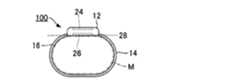
図1は、本発明の第1実施形態に係る測定装置100の側面図である。第1実施形態の測定装置100は、被験者の生体情報を非侵襲的に測定する生体計測機器であり、被験者の身体のうち測定対象となる部位(以下「測定部位」という)Mに装着される。第1実施形態の測定装置100は、筐体部12とベルト14とを具備する腕時計型の携帯機器であり、測定部位Mの例示である手首にベルト14を巻回することで被験者の手首に装着可能である。第1実施形態の測定装置100は、被験者の手首の表面16に接触する。第1実施形態では酸素飽和度(SpO2)を生体情報として例示する。酸素飽和度は、被験者の血液中のヘモグロビンのうち酸素と結合したヘモグロビンの割合(%)を意味し、被験者の呼吸機能を評価するための指標である。<First Embodiment>
FIG. 1 is a side view of a measuring
図2は、測定装置100の機能に着目した構成図である。図2に例示される通り、第1実施形態の測定装置100は、制御装置20と記憶装置22と表示装置24と検出装置26とを具備する。制御装置20および記憶装置22は筐体部12の内部に設置される。図1に例示される通り、表示装置24(例えば液晶表示パネル)は、筐体部12の表面(例えば測定部位Mとは反対側の表面)に設置され、測定結果を含む各種の画像を制御装置20による制御のもとで表示する。 FIG. 2 is a configuration diagram focusing on the function of the measuring
図2の検出装置26は、測定部位Mの状態に応じた検出信号Pを生成するセンサーモジュールであり、例えば筐体部12のうち測定部位Mとの対向面(以下「検出面」という)28に設置される。検出面28は、平面または曲面である。図2に例示される通り、第1実施形態の検出装置26は、発光部E1と発光部E2と受光部R0とを具備する。発光部E1と発光部E2と受光部R0とは検出面28に設置され、測定部位Mからみて一方側に位置する。 2 is a sensor module that generates a detection signal P in accordance with the state of the measurement site M. For example, the surface of the
発光部E1および発光部E2の各々は、例えば発光ダイオード(LED:Light Emitting Diode)等の発光素子を含んで構成される。発光部E1(第1発光部の例示)は、波長λ1の光を測定部位Mに対して出射する光源である。発光部E2(第2発光部の例示)は、波長λ1とは異なる波長λ2の光を測定部位Mに対して出射する光源である。第1実施形態では、発光部E1が近赤外光(λ1=900nm)を出射し、発光部E2が赤色光(λ2=700nm)を出射する場合を便宜的に想定する。なお、波長λ1および波長λ2は以上の例示に限定されない。例えば、波長λ1を940nmに設定し、波長λ2を660nmに設定することも可能である。 Each of the light emitting unit E1 and the light emitting unit E2 includes a light emitting element such as a light emitting diode (LED). The light emitting unit E1 (illustrated as the first light emitting unit) is a light source that emits light of wavelength λ1 to the measurement site M. The light emitting unit E2 (illustrated as the second light emitting unit) is a light source that emits light having a wavelength λ2 different from the wavelength λ1 to the measurement site M. In the first embodiment, it is assumed for the sake of convenience that the light emitting unit E1 emits near infrared light (λ1 = 900 nm) and the light emitting unit E2 emits red light (λ2 = 700 nm). The wavelengths λ1 and λ2 are not limited to the above examples. For example, the wavelength λ1 can be set to 940 nm and the wavelength λ2 can be set to 660 nm.
発光部E1および発光部E2の各々からの出射光は、測定部位Mに入射するとともに測定部位Mの内部で反射および散乱を繰返したうえで検出面28側に出射して受光部R0に到達する。すなわち、第1実施形態の検出装置26は、反射型の光学センサーである。受光部R0は、測定部位Mから到達する光の受光レベルに応じた検出信号Pを生成する。例えば、測定部位Mに対向する受光面で光を受光するフォトダイオード(PD:Photo Diode)等の光電変換素子が受光部R0として好適に利用される。測定部位Mの血管は、心拍と同等の周期で反復的に膨張および収縮する。膨張時と収縮時とで血管内の血液による吸光量は相違するから、測定部位Mからの受光レベルに応じて受光部R0が生成する検出信号Pは、測定部位Mの動脈の脈動成分(容積脈波)に対応した周期的な変動成分を含む脈波信号である。検出装置26は、例えば、駆動電流の供給により発光部E1および発光部E2を駆動する駆動回路と、受光部R0の出力信号を増幅およびA/D変換する出力回路(例えば増幅回路とA/D変換器)とを包含するが、図1では各回路の図示を省略した。 The emitted light from each of the light emitting part E1 and the light emitting part E2 enters the measurement site M and is repeatedly reflected and scattered inside the measurement site M, then exits to the
図2の制御装置20は、CPU(Central Processing Unit)やFPGA(Field-Programmable Gate Array)等の演算処理装置であり、測定装置100の全体を制御する。記憶装置22は、例えば不揮発性の半導体メモリーで構成され、制御装置20が実行するプログラムや制御装置20が使用する各種のデータを記憶する。第1実施形態の制御装置20は、記憶装置22に記憶されたプログラムを実行することで、被験者の酸素飽和度を測定するための複数の機能(解析部32,報知部34)を実現する。なお、制御装置20の機能を複数の集積回路に分散した構成や、制御装置20の一部または全部の機能を専用の電子回路で実現した構成も採用され得る。また、図2では制御装置20と記憶装置22とを別体の要素として図示したが、記憶装置22を内包する制御装置20を例えばASIC(Application Specific Integrated Circuit)等により実現することも可能である。 The
解析部32は、検出装置26が生成した検出信号Pから被験者の酸素飽和度Sを特定する。報知部34は、解析部32が特定した酸素飽和度Sを表示装置24に表示させる。なお、酸素飽和度Sが所定の範囲外の数値に変動した場合に、報知部34が利用者に警告(呼吸機能の障害の可能性)を報知する構成も好適である。 The
解析部32による酸素飽和度Sの特定には公知の技術が任意に採用され得る。例えば、検出信号Pから算定される変動比Φと酸素飽和度Sとの対応を利用して酸素飽和度Sを特定することが可能である。変動比Φは、以下の数式(1)で表現される通り、成分比C1に対する成分比C2の比率である。成分比C1は、発光部E1が波長λ1の光を出射したときの検出信号Pの変動成分Q1(AC)と定常成分Q1(DC)との強度比であり、成分比C2は、発光部E2が波長λ2の光を出射したときの検出信号Pの変動成分Q2(AC)と定常成分Q2(DC)との強度比である。変動成分Q1(AC)および変動成分Q2(AC)は、被験者の動脈の脈動に連動して周期的に変動する成分(脈波成分)であり、定常成分Q1(DC)および定常成分Q2(DC)は、時間的に定常的に維持される成分である。数式(1)の変動比Φと酸素飽和度Sとは相互に相関する。
解析部32は、脈拍と比較して充分に短い周期で発光部E1と発光部E2とを交互に発光させたときの検出信号Pの解析により、変動成分Q1(AC)および定常成分Q1(DC)と変動成分Q2(AC)および定常成分Q2(DC)とを抽出して変動比Φを算定する。そして、解析部32は、変動比Φの各数値と酸素飽和度Sの各数値とを相互に対応させたテーブルを参照して、検出信号Pから算定した変動比Φに対応する酸素飽和度Sを測定結果として特定する。 The
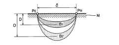
図3に例示される通り、任意の発光点PEから出射して測定部位Mの内部を通過した光を受光点PRで受光する状況を想定する。図4は、図3の測定部位Mの内部における光伝搬をシミュレーションした結果である。図4では、発光点PEから受光点PRまでの距離(以下「発光-受光間距離」という)δと、測定部位Mの内部で光が到達する深度(生体表面からの距離)Dとの関係が、緑色光(波長λ=520nm)と赤色光(波長λ=700nm)と近赤外光(波長λ=900nm)との各々について図示されている。光伝搬のシミュレーションは、散乱の事象では無損失であり散乱の事象間ではランベルト・ベール(Lambert-Beer)の法則により光減衰するという条件を採用したモンテカルロ法である。散乱の自由行程Lおよび吸収係数Aは、生体の真皮について想定される図4の数値に設定した。図4の深度Dは、発光点PEから受光点PRに到達した光子が測定部位Mの内部で最も多く通過した深度を意味する。具体的には、以下の数式(2)で表現される通り、発光点PEと受光点PRとの間に設定された仮想的な垂直断面内において光子数に応じた加重値Wで深度lを加重することで、代表的な深度Dを算定することが可能である。なお、数式(2)の記号zは、測定部位Mの深さ方向に平行な座標軸を意味する。
図4から理解される通り、発光点PEから測定部位Mに入射した光が測定部位Mの内部の深い位置まで到達する度合(以下「深達度」という)は波長λに応じて相違する。具体的には、緑色光の深達度は近赤外光の深達度を下回り、赤色光の深達度は近赤外光の深達度を上回るという傾向がある。すなわち、近赤外光は、緑色光と比較して測定部位Mの内部の深部まで到達し易く、赤色光は、近赤外光や緑色光と比較して測定部位Mの内部の深部まで到達し易い。例えば、発光-受光間距離δが6mmである場合を想定すると、近赤外光は測定部位Mの表面から2.31mmの深度Dまで到達するのに対し、赤色光は測定部位Mの表面から2.45mmの深度Dまで到達する。以上の説明から理解される通り、第1実施形態では、発光部E2から出射される赤色光(λ2=700nm)の深達度が、発光部E1から出射される近赤外光(λ1=900nm)の深達度を上回る。 As understood from FIG. 4, the degree to which the light incident on the measurement site M from the light emission point PE reaches a deep position inside the measurement site M (hereinafter referred to as “depth penetration”) varies depending on the wavelength λ. Specifically, the depth of green light is less than the depth of near infrared light, and the depth of red light tends to exceed the depth of near infrared light. That is, near-infrared light is likely to reach deep inside the measurement site M compared to green light, and red light reaches deep inside the measurement site M compared to near-infrared light and green light. Easy to do. For example, assuming that the distance δ between light emission and light reception is 6 mm, near-infrared light reaches a depth D of 2.31 mm from the surface of the measurement site M, while red light travels from the surface of the measurement site M. It reaches a depth D of 2.45 mm. As understood from the above description, in the first embodiment, the depth of the red light (λ2 = 700 nm) emitted from the light emitting unit E2 is determined by the near infrared light (λ1 = 900 nm) emitted from the light emitting unit E1. ) Exceeding the depth of penetration.
以上の通り、深達度は波長λに依存するから、発光-受光間距離δを共通させた状況で相異なる波長λの光を発光点PEから出射した場合には、図3に例示される通り、発光点PEから受光点PRに到達する光が測定部位Mの内部で伝搬する範囲(以下「伝搬範囲」という)Bの深度が波長λに応じて相違する。伝搬範囲Bは、所定値を上回る強度の光が分布する範囲(いわゆるバナナシェイプ)を意味する。 As described above, since the depth of penetration depends on the wavelength λ, when light of different wavelengths λ is emitted from the light emitting point PE in a situation where the distance δ between light emission and light reception is made common, it is exemplified in FIG. As described above, the depth of the range (hereinafter referred to as “propagation range”) B in which the light reaching the light receiving point PR from the light emitting point PE propagates inside the measurement site M differs depending on the wavelength λ. The propagation range B means a range in which light having an intensity exceeding a predetermined value is distributed (so-called banana shape).
例えば、受光部R0が設置された受光点PRから等距離の発光点PEに発光部E1および発光部E2を設置した構成(以下「対比例」という)では、図3に例示される通り、発光部E1からの出射光の伝搬範囲B1と発光部E2からの出射光の伝搬範囲B2とで深度が相違する。具体的には、発光部E2が出射する赤色光の伝搬範囲B2は、発光部E1が出射する近赤外光の伝搬範囲B1と比較して深い位置に分布する。すなわち、対比例の構成では、発光部E1および発光部E2の各々からの出射光が、測定部位Mの内部で波長λ毎に相異なる部位(深度)を通過して受光部R0に到達する。 For example, in the configuration in which the light emitting part E1 and the light emitting part E2 are installed at the light emitting point PE equidistant from the light receiving point PR where the light receiving part R0 is installed (hereinafter referred to as “comparative”), as shown in FIG. The depth differs between the propagation range B1 of the outgoing light from the part E1 and the propagation range B2 of the outgoing light from the light emitting part E2. Specifically, the propagation range B2 of red light emitted from the light emitting unit E2 is distributed at a deeper position than the propagation range B1 of near infrared light emitted from the light emitting unit E1. That is, in the comparative configuration, the emitted light from each of the light emitting part E1 and the light emitting part E2 passes through different parts (depths) for each wavelength λ inside the measurement part M and reaches the light receiving part R0.
以上の例示のように発光部E1と発光部E2との間で出射光の伝搬範囲Bが乖離する状況では、発光部E1の出射光が通過する部位と発光部E2の出射光が通過する部位との間で、測定部位Mの内部組織の種類(例えば表皮,真皮)や血管の密度等が相違するから、吸光度や濃度等の光学特性も相違し得る。したがって、酸素飽和度Sの誤差が大きいという問題がある。以上の事情を考慮して、第1実施形態では、発光部E1が出射する波長λ1の光が到達する深度Dと発光部E2が出射する波長λ2の光が到達する深度Dとが近付くように、発光部E1と発光部E2と受光部R0との位置が選定される。 In the situation where the propagation range B of the emitted light is deviated between the light emitting part E1 and the light emitting part E2 as illustrated above, the part through which the emitted light from the light emitting part E1 passes and the part through which the emitted light from the light emitting part E2 passes. Since the types of internal tissues of the measurement site M (for example, epidermis, dermis), blood vessel density, and the like are different from each other, optical characteristics such as absorbance and concentration can also be different. Therefore, there is a problem that the error of the oxygen saturation S is large. In consideration of the above circumstances, in the first embodiment, the depth D at which the light of the wavelength λ1 emitted from the light emitting unit E1 reaches and the depth D at which the light of the wavelength λ2 emitted from the light emitting unit E2 approaches are close to each other. The positions of the light emitting part E1, the light emitting part E2, and the light receiving part R0 are selected.
図4から理解される通り、発光-受光間距離δが大きいほど、測定部位Mの内部で光が到達する深度Dが増加する(より深い位置まで到達する)という傾向がある。以上の傾向を考慮して、第1実施形態では、深達度が低い光(測定部位Mの深い位置まで到達し難い光)ほど、受光部R0に対して遠い位置から出射されるように、発光部E1と発光部E2と受光部R0との位置が選定される。 As understood from FIG. 4, as the light emission-light reception distance δ increases, the depth D at which the light reaches inside the measurement site M tends to increase (it reaches a deeper position). In consideration of the above tendency, in the first embodiment, light having a low depth of penetration (light that does not easily reach the deep position of the measurement site M) is emitted from a position far from the light receiving unit R0. The positions of the light emitting part E1, the light emitting part E2, and the light receiving part R0 are selected.
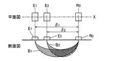
図5は、発光部E1と発光部E2と受光部R0との位置関係を例示する平面図および断面図である。前述の通り、第1実施形態では、発光部E2から出射する赤色光の深達度が、発光部E1から出射する近赤外光の深達度を上回る。したがって、図5に例示される通り、発光部E1と受光部R0との距離δ1が、発光部E2と受光部R0との距離δ2を上回るように(δ1>δ2)、発光部E1および発光部E2の各々と受光部R0との位置が選定される。 FIG. 5 is a plan view and a cross-sectional view illustrating the positional relationship among the light emitting part E1, the light emitting part E2, and the light receiving part R0. As described above, in the first embodiment, the depth of red light emitted from the light emitting portion E2 exceeds the depth of near infrared light emitted from the light emitting portion E1. Therefore, as illustrated in FIG. 5, the light emitting unit E1 and the light emitting unit are configured such that the distance δ1 between the light emitting unit E1 and the light receiving unit R0 exceeds the distance δ2 between the light emitting unit E2 and the light receiving unit R0 (δ1> δ2). The position of each E2 and the light receiving portion R0 is selected.
図5に例示される通り、発光部E1と発光部E2と受光部R0とは、平面視で(すなわち検出面28に垂直な方向からみて)、検出面28における直線X上に位置する。具体的には、発光部E1と発光部E2と受光部R0との各々の中心が直線X上に位置する。第1実施形態では、発光部E2を挟んで受光部R0とは反対側に発光部E1が位置する。発光部E1と受光部R0とを結ぶ直線X上に発光部E2が位置する構成や、発光部E1と発光部E2と受光部R0とが直線状に配列する構成とも換言され得る。以上の構成を採用する結果、第1実施形態では、図5に例示される通り、発光部E1から出射された近赤外光の伝搬範囲B1と、発光部E2から出射された赤色光の伝搬範囲B2とが相互に重複する。 As illustrated in FIG. 5, the light emitting unit E1, the light emitting unit E2, and the light receiving unit R0 are located on a straight line X on the
例えば、図4に例示される通り、測定部位Mの表面から2.15mmの深度Dに発光部E1および発光部E2の双方の光を通過させる場合には、受光部R0から5.5mm程度の距離δ1だけ離間した位置に発光部E1が配置され、受光部R0から5mm程度の距離δ2だけ離間した位置に発光部E2が配置される。発光部E1と発光部E2との距離(例えば中心間距離)は、例えば300μm以上かつ500μm以下の範囲に選定される。 For example, as illustrated in FIG. 4, when the light from both the light emitting part E1 and the light emitting part E2 is allowed to pass through the depth D of 2.15 mm from the surface of the measurement site M, the light receiving part R0 is about 5.5 mm. The light emitting part E1 is arranged at a position separated by a distance δ1, and the light emitting part E2 is arranged at a position separated by a distance δ2 of about 5 mm from the light receiving part R0. The distance (for example, the distance between the centers) between the light emitting part E1 and the light emitting part E2 is selected in the range of, for example, 300 μm or more and 500 μm or less.
以上の通り、第1実施形態では、発光部E1が波長λ1(第1波長の例示)の近赤外光を出射するとともに、測定部位Mに対する深達度が近赤外光を上回る波長λ2(第2波長の例示)の赤色光を発光部E2が出射する構成のもとで、発光部E1と受光部R0との距離δ1が発光部E2と受光部R0との距離δ2を上回る。したがって、発光部E1と発光部E2とが受光部R0から等距離に位置する対比例と比較して、図5に例示される通り、発光部E1が出射した近赤外光の伝搬範囲B1と、発光部E2が出射した赤色光の伝搬範囲B2とを相互に近接または重複させることが可能である。以上の構成では、発光部E1からの出射光と発光部E2からの出射光とで伝搬範囲B(B1,B2)が乖離する構成と比較して、発光部E1の出射光の伝搬範囲B1と発光部E2の出射光の伝搬範囲B2との間で、測定部位Mの内部組織の種類や血管の密度等が近似するから、吸光度や濃度等の光学特性も近似し得る。したがって、伝搬範囲Bの相違に起因した誤差を抑制して酸素飽和度Sを高精度に特定できるという利点がある。 As described above, in the first embodiment, the light emitting unit E1 emits near-infrared light having the wavelength λ1 (illustrated as the first wavelength), and has a wavelength λ2 (the penetration depth with respect to the measurement site M exceeds that of the near-infrared light. Under the configuration in which the light emitting unit E2 emits red light having a second wavelength), the distance δ1 between the light emitting unit E1 and the light receiving unit R0 exceeds the distance δ2 between the light emitting unit E2 and the light receiving unit R0. Therefore, as compared with the proportionality in which the light emitting part E1 and the light emitting part E2 are located at the same distance from the light receiving part R0, as illustrated in FIG. 5, the propagation range B1 of the near infrared light emitted from the light emitting part E1 The red light propagation range B2 emitted from the light emitting unit E2 can be close to or overlap each other. In the above configuration, compared with the configuration in which the propagation range B (B1, B2) is different between the light emitted from the light emitting unit E1 and the light emitted from the light emitting unit E2, the propagation range B1 of the light emitted from the light emitting unit E1 is Since the type of internal tissue of the measurement site M, the density of blood vessels, and the like are approximated with the propagation range B2 of the emitted light of the light emitting unit E2, optical characteristics such as absorbance and concentration can also be approximated. Therefore, there is an advantage that the error due to the difference in the propagation range B can be suppressed and the oxygen saturation S can be specified with high accuracy.
また、第1実施形態では、発光部E1と発光部E2と受光部R0とが直線X上に位置する。したがって、発光部E1と発光部E2と受光部R0とが直線上に位置しない構成と比較して、発光部E1からの出射光の伝搬範囲B1と発光部E2からの出射光の伝搬範囲B2とを充分に近接または重複させることが可能である。したがって、酸素飽和度Sを高精度に特定できるという前述の効果は各別に顕著である。 In the first embodiment, the light emitting unit E1, the light emitting unit E2, and the light receiving unit R0 are positioned on the straight line X. Therefore, compared with a configuration in which the light emitting part E1, the light emitting part E2, and the light receiving part R0 are not positioned on a straight line, the propagation range B1 of the outgoing light from the light emitting part E1 and the propagation range B2 of the outgoing light from the light emitting part E2 Can be sufficiently close or overlapping. Therefore, the above-mentioned effect that the oxygen saturation S can be specified with high accuracy is remarkable for each.
ところで、伝搬範囲Bの相違に起因した酸素飽和度Sの誤差は、第1実施形態の例示のように、発光部E1および発光部E2と受光部R0とが測定部位Mに対して一方側に位置する反射型の光学センサーにおいて顕在化する課題である。他方、発光部E1および発光部E2が測定部位Mを挟んで受光部R0とは反対側に位置する透過型の光学センサーでは、発光部E1からの出射光と発光部E2からの出射光とが測定部位Mの内部で相互に近接した経路を伝搬して受光部R0に到達する。したがって、伝搬範囲Bの相違に起因した酸素飽和度Sの誤差は特段の問題とならない。以上の事情を考慮すると、発光部E1と受光部R0との距離δ1が発光部E2と受光部R0との距離δ2を上回る構成は、反射型の光学センサーに特に有効であると言える。 By the way, the error of the oxygen saturation S due to the difference in the propagation range B is that the light emitting part E1, the light emitting part E2, and the light receiving part R0 are on one side with respect to the measurement site M as illustrated in the first embodiment. This is a problem that manifests itself in a reflective optical sensor that is positioned. On the other hand, in the transmissive optical sensor in which the light emitting part E1 and the light emitting part E2 are located on the opposite side of the light receiving part R0 across the measurement site M, the emitted light from the light emitting part E1 and the emitted light from the light emitting part E2 are It propagates along a path close to each other inside the measurement site M and reaches the light receiving part R0. Therefore, the error of the oxygen saturation S caused by the difference in the propagation range B does not become a special problem. Considering the above circumstances, it can be said that the configuration in which the distance δ1 between the light emitting portion E1 and the light receiving portion R0 exceeds the distance δ2 between the light emitting portion E2 and the light receiving portion R0 is particularly effective for the reflective optical sensor.
<第2実施形態>
本発明の第2実施形態を説明する。なお、以下に例示する各構成において作用や機能が第1実施形態と同様である要素については、第1実施形態の説明で使用した符号を流用して各々の詳細な説明を適宜に省略する。Second Embodiment
A second embodiment of the present invention will be described. In addition, about the element which an effect | action and function are the same as that of 1st Embodiment in each structure illustrated below, the code | symbol used by description of 1st Embodiment is diverted, and each detailed description is abbreviate | omitted suitably.
図6は、第2実施形態における発光部E1と発光部E2と受光部R0との位置関係を例示する平面図および断面図である。図6に例示される通り、第2実施形態の受光部R0は、検出面28に設置された受光部R1(第1受光部の例示)と受光部R2(第2受光部の例示)とを包含する。受光部R1および受光部R2は、測定部位Mに対向する受光面で光を受光するフォトダイオード等の光電変換素子である。受光部R1は、発光部E1から出射して測定部位Mを通過した近赤外光(波長λ1)を受光し、受光レベルに応じた検出信号P1を生成する。受光部R2は、発光部E2から出射して測定部位Mを通過した赤色光(波長λ2)を受光し、受光レベルに応じた検出信号P2を生成する。解析部32は、受光部R1が生成した検出信号P1から前掲の数式(1)の成分比C1を算定し、受光部R2が生成した検出信号P2から数式(1)の成分比C2を算定する。成分比C1と成分比C2との変動比Φから解析部32が酸素飽和度Sを特定する構成および方法は第1実施形態と同様である。 FIG. 6 is a plan view and a cross-sectional view illustrating the positional relationship among the light emitting part E1, the light emitting part E2, and the light receiving part R0 in the second embodiment. As illustrated in FIG. 6, the light receiving unit R 0 of the second embodiment includes a light receiving unit R 1 (an example of the first light receiving unit) and a light receiving unit R 2 (an example of the second light receiving unit) installed on the
図6に例示される通り、発光部E1と発光部E2と受光部R1と受光部R2とは、平面視で検出面28における直線X上に位置する。発光部E1と受光部R1との距離δ1は、発光部E2と受光部R2との距離δ2を上回る(δ1>δ2)。具体的には、発光部E2および受光部R2は、発光部E1と受光部R1との間に位置する。 As illustrated in FIG. 6, the light emitting unit E1, the light emitting unit E2, the light receiving unit R1, and the light receiving unit R2 are located on a straight line X on the
以上に説明した通り、第2実施形態では、発光部E1が波長λ1の近赤外光を出射するとともに発光部E2が波長λ2の赤色光を発光部E2が出射する構成のもとで、発光部E1と受光部R1との距離δ1が発光部E2と受光部R2との距離δ2を上回る。以上の構成では、図6に例示される通り、発光部E1からの出射光の伝搬範囲B1と、発光部E2からの出射光の伝搬範囲B2とは相互に近接または重複する。したがって、第1実施形態と同様に、発光部E1と発光部E2との伝搬範囲Bの相違に起因した誤差を抑制して酸素飽和度Sを高精度に特定できるという利点がある。 As described above, in the second embodiment, the light emitting unit E1 emits near-infrared light having the wavelength λ1, and the light emitting unit E2 emits red light having the wavelength λ2. The distance δ1 between the part E1 and the light receiving part R1 exceeds the distance δ2 between the light emitting part E2 and the light receiving part R2. In the above configuration, as illustrated in FIG. 6, the propagation range B1 of the emitted light from the light emitting unit E1 and the propagation range B2 of the emitted light from the light emitting unit E2 are close to or overlap each other. Therefore, as in the first embodiment, there is an advantage that the oxygen saturation S can be specified with high accuracy while suppressing errors due to the difference in the propagation range B between the light emitting part E1 and the light emitting part E2.
第2実施形態では特に、発光部E1と発光部E2と受光部R1と受光部R2とが直線X上に位置するから、伝搬範囲B1と伝搬範囲B2とを充分に近接または重複させることが可能である。したがって、酸素飽和度Sを高精度に特定できるという前述の効果は各別に顕著である。しかも、第2実施形態では、発光部E2および受光部R2が発光部E1と受光部R1との間に位置するから、伝搬範囲B1と伝搬範囲B2との相違に起因した酸素飽和度Sの誤差を充分に抑制することが可能である。 Particularly in the second embodiment, since the light emitting part E1, the light emitting part E2, the light receiving part R1, and the light receiving part R2 are located on the straight line X, the propagation range B1 and the propagation range B2 can be sufficiently close to each other or overlapped. It is. Therefore, the above-mentioned effect that the oxygen saturation S can be specified with high accuracy is remarkable for each. Moreover, in the second embodiment, since the light emitting part E2 and the light receiving part R2 are located between the light emitting part E1 and the light receiving part R1, the error of the oxygen saturation S due to the difference between the propagation range B1 and the propagation range B2 Can be sufficiently suppressed.
<第3実施形態>
図7は、第3実施形態における発光部E1と発光部E2と受光部R0との位置関係を例示する平面図である。図7に例示される通り、第3実施形態の受光部R0は、第2実施形態と同様に受光部R1と受光部R2とを包含する。受光部R1は、発光部E1から出射して測定部位Mを通過した近赤外光(波長λ1)を受光し、受光レベルに応じた検出信号P1を生成する。受光部R2は、発光部E2から出射して測定部位Mを通過した赤色光(波長λ2)を受光し、受光レベルに応じた検出信号P2を生成する。検出信号P1および検出信号P2から解析部32が酸素飽和度Sを特定する構成および方法は第2実施形態と同様である。<Third Embodiment>
FIG. 7 is a plan view illustrating the positional relationship among the light emitting unit E1, the light emitting unit E2, and the light receiving unit R0 in the third embodiment. As illustrated in FIG. 7, the light receiving unit R0 of the third embodiment includes a light receiving unit R1 and a light receiving unit R2 as in the second embodiment. The light receiving unit R1 receives near infrared light (wavelength λ1) emitted from the light emitting unit E1 and passed through the measurement site M, and generates a detection signal P1 corresponding to the light receiving level. The light receiving unit R2 receives the red light (wavelength λ2) emitted from the light emitting unit E2 and passed through the measurement site M, and generates a detection signal P2 corresponding to the received light level. The configuration and method for the
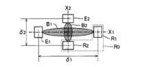
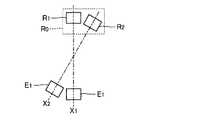
図7に例示される通り、発光部E1と受光部R1とを通過する直線X1と、発光部E2と受光部R2とを通過する直線X2とは、平面視で相互に交差する。直線X1は、発光部E1の中心と受光部R1の中心とを通過し、直線X2は、発光部E2の中心と受光部R2の中心とを通過する。図7に例示される通り、直線X1と直線X2とは相互に直交する。 As illustrated in FIG. 7, a straight line X1 passing through the light emitting part E1 and the light receiving part R1 and a straight line X2 passing through the light emitting part E2 and the light receiving part R2 intersect each other in plan view. The straight line X1 passes through the center of the light emitting part E1 and the center of the light receiving part R1, and the straight line X2 passes through the center of the light emitting part E2 and the center of the light receiving part R2. As illustrated in FIG. 7, the straight line X1 and the straight line X2 are orthogonal to each other.
直線X1は、発光部E2と受光部R2との中点にて直線X2に交差する。同様に、直線X2は、発光部E1と受光部R1との中点にて直線X1に交差する。発光部E1と受光部R1との距離δ1が、発光部E2と受光部R2との距離δ2を上回るという条件は、第1実施形態および第2実施形態と同様である。以上の説明から理解される通り、第2実施形態では、発光部E1と発光部E2と受光部R1と受光部R2とが、検出面28に画定される菱形の各頂点に位置する。以上の構成によれば、発光部E1からの出射光の伝搬範囲B1と、発光部E2の出射光の伝搬範囲B2とが、直線X1と直線X2との交点の下方において相互に近接または重複する。 The straight line X1 intersects the straight line X2 at the midpoint between the light emitting part E2 and the light receiving part R2. Similarly, the straight line X2 intersects the straight line X1 at the midpoint between the light emitting part E1 and the light receiving part R1. The condition that the distance δ1 between the light emitting part E1 and the light receiving part R1 exceeds the distance δ2 between the light emitting part E2 and the light receiving part R2 is the same as in the first and second embodiments. As understood from the above description, in the second embodiment, the light emitting part E1, the light emitting part E2, the light receiving part R1, and the light receiving part R2 are located at the vertices of the rhombus defined on the detection surface. According to the above configuration, the propagation range B1 of the emitted light from the light emitting unit E1 and the propagation range B2 of the emitted light of the light emitting unit E2 are close to each other or overlap below the intersection of the straight line X1 and the straight line X2. .
以上に説明した通り、第3実施形態においても、発光部E1と受光部R1との距離δ1が発光部E2と受光部R2との距離δ2を上回るから、発光部E1からの出射光の伝搬範囲B1と発光部E2からの出射光の伝搬範囲B2とを相互に近接または重複させることが可能である。したがって、第2実施形態と同様に、発光部E1と発光部E2との伝搬範囲Bの相違に起因した誤差を抑制して酸素飽和度Sを高精度に特定できるという利点がある。また、第3実施形態では、発光部E1および受光部R1を通過する直線X1と発光部E2および受光部R2を通過する直線X2とが相互に交差するから、発光部E1および受光部R1と発光部E2および受光部R2とを、相互間の過度な接近や干渉を回避しながら検出面28に配置できるという利点がある。 As described above, also in the third embodiment, since the distance δ1 between the light emitting part E1 and the light receiving part R1 exceeds the distance δ2 between the light emitting part E2 and the light receiving part R2, the propagation range of the emitted light from the light emitting part E1 It is possible to make B1 and the propagation range B2 of the emitted light from the light emitting part E2 close to each other or overlap each other. Therefore, as in the second embodiment, there is an advantage that the oxygen saturation S can be specified with high accuracy while suppressing errors due to the difference in the propagation range B between the light emitting part E1 and the light emitting part E2. In the third embodiment, since the straight line X1 passing through the light emitting part E1 and the light receiving part R1 and the straight line X2 passing through the light emitting part E2 and the light receiving part R2 intersect each other, the light emitting part E1 and the light receiving part R1 emit light. There is an advantage that the part E2 and the light receiving part R2 can be arranged on the
なお、図7では、直線X1と直線X2とが直交する構成を例示したが、直線X1と直線X2とが交差する角度は直角に限定されない。例えば、図8に例示される通り、直線X1と直線X2とが非直角で交差するように発光部E1と受光部R1と発光部E2と受光部R2とを配置することも可能である。なお、直線X1と直線X2とを交差させた第3実施形態の構成では、発光部E1と受光部R1との距離δ1が発光部E2と受光部R2との距離δ2を上回る構成が好適である。ただし、図8の例示のように、距離δ1と距離δ2とを同等の距離として直線X1と直線X2とを交差させた構成も採用され得る。 7 illustrates the configuration in which the straight line X1 and the straight line X2 are orthogonal to each other, the angle at which the straight line X1 and the straight line X2 intersect is not limited to a right angle. For example, as illustrated in FIG. 8, the light emitting part E1, the light receiving part R1, the light emitting part E2, and the light receiving part R2 can be arranged so that the straight line X1 and the straight line X2 intersect at a non-right angle. In the configuration of the third embodiment in which the straight line X1 and the straight line X2 intersect, it is preferable that the distance δ1 between the light emitting unit E1 and the light receiving unit R1 exceeds the distance δ2 between the light emitting unit E2 and the light receiving unit R2. . However, as illustrated in FIG. 8, a configuration in which the straight line X1 and the straight line X2 are crossed with the distance δ1 and the distance δ2 as equal distances may be employed.
<第4実施形態>
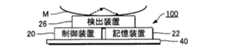
以上の各形態では、筐体部12とベルト14とを具備する携帯型の測定装置100を例示した。第4実施形態の測定装置100は、筐体部12やベルト14を含まない測定モジュールである。具体的には、図9に例示される通り、第4実施形態の測定装置100は、制御装置20と記憶装置22と検出装置26とを基板40(例えば配線基板)上に実装した構成の電子部品である。なお、図10に例示される通り、制御装置20と記憶装置22とを基板40上に実装し、制御装置20および記憶装置22と比較して測定部位Mに近い位置に検出装置26を配置した構成も好適である。例えば表示装置24が設置された筐体に第4実施形態の測定装置100(測定モジュール)を組込むことで携帯機器が構成される。制御装置20と記憶装置22と検出装置26との各々の構成や機能は、前述の各形態と同様である。なお、検出装置26の単体(制御装置20や記憶装置22を含まない部分)を、筐体部12やベルト14等を省略した測定モジュールの形態で実現することも可能である。<Fourth embodiment>
In each of the above embodiments, the
<変形例>
以上に例示した各形態は多様に変形され得る。具体的な変形の態様を以下に例示する。以下の例示から任意に選択された2以上の態様を適宜に併合することも可能である。<Modification>
Each form illustrated above can be variously modified. Specific modifications are exemplified below. Two or more aspects arbitrarily selected from the following examples can be appropriately combined.
(1)前述の各形態では、発光部E1が近赤外光を出射するとともに発光部E2が赤色光を出射する構成を例示したが、発光部E1および発光部E2による出射光の波長λは以上の例示に限定されない。例えば、発光部E1が緑色光(λ1=520nm)を出射するとともに発光部E2が近赤外光(λ2=900nm)または赤色光(λ2=700nm)を出射する構成も採用され得る。図4を参照して説明した通り、緑色光の深達度は近赤外光および赤色光の深達度を下回る。すなわち、以上に例示した各構成は、発光部E1が波長λ1の光を出射するとともに、測定部位Mに対する深達度が波長λ1の光を上回る波長λ2の光を発光部E2が出射し、発光部E1と受光部R0との距離δ1が発光部E2と受光部R0との距離δ2を上回る構成として包括的に表現される。(1) In each of the above-described embodiments, the light emitting unit E1 emits near infrared light and the light emitting unit E2 emits red light. However, the wavelength λ of light emitted from the light emitting unit E1 and the light emitting unit E2 is It is not limited to the above illustration. For example, a configuration in which the light emitting unit E1 emits green light (λ1 = 520 nm) and the light emitting unit E2 emits near infrared light (λ2 = 900 nm) or red light (λ2 = 700 nm) may be employed. As described with reference to FIG. 4, the depth of green light is less than that of near infrared light and red light. That is, in each configuration exemplified above, the light emitting unit E1 emits light of wavelength λ1, and the light emitting unit E2 emits light of wavelength λ2 whose depth of penetration to the measurement site M exceeds that of light of wavelength λ1. The distance δ1 between the part E1 and the light receiving part R0 is comprehensively expressed as a configuration that exceeds the distance δ2 between the light emitting part E2 and the light receiving part R0.
(2)酸素飽和度Sを演算で算定することも可能である。検出信号Pを利用した酸素飽和度Sの算定について以下に検討する。まず、光減衰に関するランベルト・ベールの式は以下の数式(3)で表現される。
発光部E1からの出射光の伝搬範囲B1と発光部E2からの出射光の伝搬範囲B2とが共通すると仮定すれば、数式(4)の右辺の分子および分母におけるヘモグロビン濃度Caと光路長Δlaとが消去されるから、変動比Φと酸素飽和度Sとの関係を記述する以下の数式(5)が導出される。脱酸素化ヘモグロビンのモル吸光度(Ed[λ1],Ed[λ2])および酸素化ヘモグロビンのモル吸光度(Eo[λ1],Eo[λ2])は既知であるから、検出信号Pから算定した変動比Φを解析部32が数式(5)に適用することで、酸素飽和度Sを算定することが可能である。
数式(4)から数式(5)の導出では、発光部E1からの出射光の伝搬範囲B1と発光部E2からの出射光の伝搬範囲B2とが共通すると仮定した。透過型の光学センサーでは、前述の通り、発光部E1からの出射光と発光部E2からの出射光とが測定部位Mの内部で相互に近接した経路を伝搬するから、前述の仮定が適切に成立する。しかし、反射型の光学センサーにおいて伝搬範囲B1と伝搬範囲B2とが実際には相違する場合には前述の仮定が有効に成立しないから、数式(5)では酸素飽和度Sを高精度に算定することは困難である。 In derivation of Equation (5) from Equation (4), it is assumed that the propagation range B1 of the emitted light from the light emitting portion E1 and the propagation range B2 of the emitted light from the light emitting portion E2 are common. In the transmission type optical sensor, as described above, the outgoing light from the light emitting part E1 and the outgoing light from the light emitting part E2 propagate along a path close to each other inside the measurement site M. To establish. However, if the propagation range B1 and the propagation range B2 are actually different in the reflection type optical sensor, the above assumption is not valid, so that the oxygen saturation S is calculated with high accuracy in the equation (5). It is difficult.
前述の各形態では、発光部E1からの出射光の伝搬範囲B1と発光部E2からの出射光の伝搬範囲B2とを相互に近接または重複させ得るから、数式(4)から数式(5)の導出における仮定は有効である。したがって、反射型の光学センサーにも関わらず、数式(5)の演算により酸素飽和度Sを高精度に算定できるという利点がある。 In each of the above-described embodiments, the propagation range B1 of the emitted light from the light emitting unit E1 and the propagation range B2 of the emitted light from the light emitting unit E2 can be close to each other or overlap each other. The assumptions in derivation are valid. Therefore, there is an advantage that the oxygen saturation S can be calculated with high accuracy by the calculation of Expression (5), regardless of the reflection type optical sensor.
(3)前述の各形態では、発光部E1および発光部E2の2個の発光部Eを具備する検出装置26を例示したが、検出装置26に3個以上の発光部Eを設置することも可能である。各発光部Eからの出射光の伝搬範囲Bを近接または重複させるという観点からは、発光部Eの個数に関わらず、出射光の深達度が低い発光部Eほど受光部R0から遠い位置に配置した構成が好適である。3個以上の発光部が設置された構成は、特定の2個の発光部のうちの一方を第1発光部として他方を第2発光部としたときに本発明の要件を充足すれば、他の発光部の如何に関わらず本発明の範囲に包含される。(3) In each of the above-described embodiments, the
(4)前述の各形態では、被験者の手首に装着可能な測定装置100を例示したが、測定装置100の具体的な形態(装着位置)は任意である。例えば、被験者の身体に貼付可能なパッチ型,被験者の耳介に装着可能なイヤリング型,被験者の指先に装着可能な指装着型(例えば着爪型),被験者の頭部に装着可能なヘッドマウント型等、任意の形態の測定装置100が採用され得る。ただし、例えば指装着型等の測定装置100を装着した状態では日常生活に支障がある可能性が想定されるから、日常生活に支障なく常時的に酸素飽和度Sを測定するという観点からは、被験者の手首に装着可能な前述の各形態の測定装置100が特に好適である。なお、腕時計等の各種の電子機器に装着(例えば外付け)される形態の測定装置100も実現され得る。(4) In each of the above-described embodiments, the
(5)前述の各形態では酸素飽和度Sを測定したが、生体情報の種類は以上の例示に限定されない。例えば、脈拍や血流速,血圧を生体情報として測定する構成、および、血中グルコース濃度,ヘモグロビン濃度,血中酸素濃度,中性脂肪濃度等の各種の血液成分濃度を生体情報として測定する構成も採用され得る。なお、血流速を生体情報として測定する構成では、共振器による共振を経て射出される狭帯域でコヒーレントなレーザー光を出射するレーザー照射器が発光部Eとして好適に利用される。(5) Although the oxygen saturation S is measured in each of the above-described embodiments, the type of biological information is not limited to the above examples. For example, a configuration that measures pulse, blood flow rate, and blood pressure as biological information, and a configuration that measures various blood component concentrations such as blood glucose concentration, hemoglobin concentration, blood oxygen concentration, and neutral fat concentration as biological information. Can also be employed. In the configuration in which the blood flow rate is measured as biological information, a laser irradiator that emits a narrow-band coherent laser beam emitted through resonance by the resonator is preferably used as the light emitting unit E.
100…測定装置、12…筐体部、14…ベルト、20…制御装置、22…記憶装置、24…表示装置、26…検出装置、E1,E2…発光部、R0,R1,R2…受光部、32…解析部、34…報知部。
DESCRIPTION OF
Claims (9)
Translated fromJapanese測定部位に対する深達度が前記第1波長の光を上回る第2波長の光を出射する第2発光部と、
前記測定部位から到達する光の受光レベルに応じた検出信号を生成する受光部と、
前記検出信号に応じた生体情報を取得する解析部とを具備し、
前記第1発光部と前記第2発光部と前記受光部とは、前記測定部位に対向する検出面に設置され、前記第1発光部と前記受光部との距離は、前記第2発光部と前記受光部との距離を上回る
測定装置。A first light emitting unit that emits light of a first wavelength;
A second light-emitting unit that emits light having a second wavelength that exceeds the light having the first wavelength with respect to the measurement site;
A light receiving unit that generates a detection signal according to a light receiving level of light reaching from the measurement site;
An analysis unit that acquires biological information according to the detection signal;
The first light emitting unit, the second light emitting unit, and the light receiving unit are installed on a detection surface facing the measurement site, and the distance between the first light emitting unit and the light receiving unit is the same as that of the second light emitting unit. A measuring device that exceeds the distance from the light receiving unit.
請求項1の測定装置。The measuring apparatus according to claim 1, wherein the first light emitting unit, the second light emitting unit, and the light receiving unit are located on a straight line.
前記第1発光部から出射して前記測定部位を通過した光を受光する第1受光部と、
前記第2発光部から出射して前記測定部位を通過した光を受光する第2受光部とを含み、
前記第1発光部と前記第1受光部との距離は、前記第2発光部と前記第2受光部との距離を上回る
請求項1の測定装置。The light receiving unit is
A first light receiving portion that receives light emitted from the first light emitting portion and passed through the measurement site;
A second light receiving part for receiving light emitted from the second light emitting part and passed through the measurement site,
The measuring apparatus according to claim 1, wherein a distance between the first light emitting unit and the first light receiving unit is greater than a distance between the second light emitting unit and the second light receiving unit.
請求項3の測定装置。The measuring apparatus according to claim 3, wherein the first light emitting unit, the second light emitting unit, the first light receiving unit, and the second light receiving unit are located on a straight line.
請求項4の測定装置。The measurement apparatus according to claim 4, wherein the first light emitting unit and the first light receiving unit are located between the second light emitting unit and the second light receiving unit.
請求項3の測定装置。The measuring apparatus according to claim 3, wherein a straight line passing through the first light emitting unit and the first light receiving unit and a straight line passing through the second light emitting unit and the second light receiving unit intersect each other.
前記第2波長の光は、赤色光である
請求項1から請求項6の何れかの測定装置。The light of the first wavelength is near infrared light,
The measuring apparatus according to claim 1, wherein the second wavelength light is red light.
前記第2波長の光は、近赤外光または赤色光である
請求項1から請求項6の何れかの測定装置。The light of the first wavelength is green light;
The measuring apparatus according to claim 1, wherein the second wavelength light is near infrared light or red light.
第1波長の光を出射する第1発光部と、
測定部位に対する深達度が前記第1波長の光を上回る第2波長の光を出射する第2発光部と、
前記測定部位から到達する光の受光レベルに応じた検出信号を生成する受光部と
を具備し、
前記第1発光部と前記第2発光部と前記受光部とは、前記測定部位に対向する検出面に設置され、前記第1発光部と前記受光部との距離は、前記第2発光部と前記受光部との距離を上回る
検出装置。
A detection device that generates a detection signal used for generation of biological information,
A first light emitting unit that emits light of a first wavelength;
A second light-emitting unit that emits light having a second wavelength that exceeds the light having the first wavelength with respect to the measurement site;
A light receiving unit that generates a detection signal according to a light receiving level of light reaching from the measurement site,
The first light emitting unit, the second light emitting unit, and the light receiving unit are installed on a detection surface facing the measurement site, and the distance between the first light emitting unit and the light receiving unit is the same as that of the second light emitting unit. A detection device exceeding a distance from the light receiving unit.
Priority Applications (3)
| Application Number | Priority Date | Filing Date | Title |
|---|---|---|---|
| JP2016042293AJP6672899B2 (en) | 2016-03-04 | 2016-03-04 | Measuring and detecting devices |
| CN201710075003.5ACN107149478A (en) | 2016-03-04 | 2017-02-10 | Determine device and detection means |
| US15/437,724US20170251963A1 (en) | 2016-03-04 | 2017-02-21 | Measurement apparatus and detection device |
Applications Claiming Priority (1)
| Application Number | Priority Date | Filing Date | Title |
|---|---|---|---|
| JP2016042293AJP6672899B2 (en) | 2016-03-04 | 2016-03-04 | Measuring and detecting devices |
Publications (2)
| Publication Number | Publication Date |
|---|---|
| JP2017153876Atrue JP2017153876A (en) | 2017-09-07 |
| JP6672899B2 JP6672899B2 (en) | 2020-03-25 |
Family
ID=59723039
Family Applications (1)
| Application Number | Title | Priority Date | Filing Date |
|---|---|---|---|
| JP2016042293AActiveJP6672899B2 (en) | 2016-03-04 | 2016-03-04 | Measuring and detecting devices |
Country Status (3)
| Country | Link |
|---|---|
| US (1) | US20170251963A1 (en) |
| JP (1) | JP6672899B2 (en) |
| CN (1) | CN107149478A (en) |
Cited By (4)
| Publication number | Priority date | Publication date | Assignee | Title |
|---|---|---|---|---|
| US10768095B2 (en) | 2018-08-23 | 2020-09-08 | Ricoh Company, Ltd | Optical sensor |
| EP3730053A4 (en)* | 2017-12-20 | 2021-08-04 | Medical Photonics Co., Ltd. | Lipid measurement device and method therefor |
| JP2023507412A (en)* | 2019-12-17 | 2023-02-22 | ユニバーシティ オブ ユタ リサーチ ファウンデーション | Cardiac Tissue Characterization Using Catheterized Light Scattering Spectroscopy |
| US11744519B2 (en) | 2018-07-31 | 2023-09-05 | Seiko Epson Corporation | Biological information measurement device |
Families Citing this family (15)
| Publication number | Priority date | Publication date | Assignee | Title |
|---|---|---|---|---|
| CN109875572A (en)* | 2018-11-09 | 2019-06-14 | 唐庆圆 | Physiological parameter measurement device and method |
| KR102696905B1 (en) | 2018-11-20 | 2024-08-20 | 삼성전자주식회사 | Electronic device and method for obtaining information regarding blood glucose of user |
| CN109589095B (en)* | 2019-01-31 | 2024-07-02 | 深圳市爱都科技有限公司 | Wearable device |
| CN111493846B (en)* | 2019-01-31 | 2023-03-21 | 深圳市爱都科技有限公司 | Calculation method of blood oxygen saturation and heart rate value and wearable device |
| CN109924960A (en)* | 2019-01-31 | 2019-06-25 | 深圳市爱都科技有限公司 | A kind of blood oxygen saturation, the calculation method and wearable device of heart rate value and pressure rating |
| CN111493886A (en)* | 2019-01-31 | 2020-08-07 | 深圳市爱都科技有限公司 | Calculation method of blood oxygen saturation and pressure level and wearable device |
| US11857298B1 (en) | 2019-09-06 | 2024-01-02 | Apple Inc. | Devices having matter differentiation detectors |
| US11717197B2 (en)* | 2019-09-27 | 2023-08-08 | Apple Inc. | Physiological monitoring system for measuring oxygen saturation |
| US11573351B2 (en) | 2020-03-06 | 2023-02-07 | Apple, Inc. | Optical sensor having a magnetic optical barrier |
| US12204289B1 (en) | 2020-09-11 | 2025-01-21 | Apple Inc. | Device removal indication using different object proximity thresholds |
| US11723563B1 (en) | 2020-09-11 | 2023-08-15 | Apple Inc. | Correcting for emitted light wavelength variation in blood-oxygen saturation measurements at wearable electronic device |
| US12074244B2 (en) | 2020-09-14 | 2024-08-27 | Apple Inc. | Optical sensor package with magnetic component for device attachment |
| US12164027B1 (en) | 2020-09-14 | 2024-12-10 | Apple Inc. | Multi-pathway distance measurements for optical sensors |
| CN112244804A (en)* | 2020-11-06 | 2021-01-22 | 深圳市爱都科技有限公司 | Physiological monitoring device and electronic equipment |
| JP2023123924A (en)* | 2022-02-25 | 2023-09-06 | セイコーエプソン株式会社 | Detection device and measuring device |
Citations (5)
| Publication number | Priority date | Publication date | Assignee | Title |
|---|---|---|---|---|
| JPH04215742A (en)* | 1990-02-15 | 1992-08-06 | Hewlett Packard Co <Hp> | Sensor and oxygen saturation measuring device for non-invasive measurement of oxygen saturation |
| JPH05317295A (en)* | 1992-05-26 | 1993-12-03 | Omron Corp | Probe for measuring oxygen of living body tissue |
| JP2004041815A (en)* | 2003-11-25 | 2004-02-12 | Hitachi Ltd | Biological light measurement device |
| JP2004150961A (en)* | 2002-10-30 | 2004-05-27 | Japan Science & Technology Agency | Optical measuring device and optical measuring method |
| WO2015159692A1 (en)* | 2014-04-14 | 2015-10-22 | 株式会社村田製作所 | Pulse wave propagation time measurement device and biological state estimation device |
Family Cites Families (9)
| Publication number | Priority date | Publication date | Assignee | Title |
|---|---|---|---|---|
| US5873821A (en)* | 1992-05-18 | 1999-02-23 | Non-Invasive Technology, Inc. | Lateralization spectrophotometer |
| US5830137A (en)* | 1996-11-18 | 1998-11-03 | University Of South Florida | Green light pulse oximeter |
| US6587703B2 (en)* | 2000-09-18 | 2003-07-01 | Photonify Technologies, Inc. | System and method for measuring absolute oxygen saturation |
| US6516209B2 (en)* | 2000-08-04 | 2003-02-04 | Photonify Technologies, Inc. | Self-calibrating optical imaging system |
| CN1268286C (en)* | 2002-01-25 | 2006-08-09 | 松下电器产业株式会社 | Optical biological information measurement method and optical biological information measurement device |
| EP1520514A1 (en)* | 2003-10-02 | 2005-04-06 | Matsushita Electric Industrial Co., Ltd. | Optical biological information measuring apparatus and method |
| US8380272B2 (en)* | 2007-12-21 | 2013-02-19 | Covidien Lp | Physiological sensor |
| JP2015039542A (en)* | 2013-08-22 | 2015-03-02 | セイコーエプソン株式会社 | Pulse wave measuring device |
| CN204306817U (en)* | 2014-10-30 | 2015-05-06 | 加丁(北京)科技有限公司 | Wearable electronic |
- 2016
- 2016-03-04JPJP2016042293Apatent/JP6672899B2/enactiveActive
- 2017
- 2017-02-10CNCN201710075003.5Apatent/CN107149478A/enactivePending
- 2017-02-21USUS15/437,724patent/US20170251963A1/ennot_activeAbandoned
Patent Citations (5)
| Publication number | Priority date | Publication date | Assignee | Title |
|---|---|---|---|---|
| JPH04215742A (en)* | 1990-02-15 | 1992-08-06 | Hewlett Packard Co <Hp> | Sensor and oxygen saturation measuring device for non-invasive measurement of oxygen saturation |
| JPH05317295A (en)* | 1992-05-26 | 1993-12-03 | Omron Corp | Probe for measuring oxygen of living body tissue |
| JP2004150961A (en)* | 2002-10-30 | 2004-05-27 | Japan Science & Technology Agency | Optical measuring device and optical measuring method |
| JP2004041815A (en)* | 2003-11-25 | 2004-02-12 | Hitachi Ltd | Biological light measurement device |
| WO2015159692A1 (en)* | 2014-04-14 | 2015-10-22 | 株式会社村田製作所 | Pulse wave propagation time measurement device and biological state estimation device |
Cited By (5)
| Publication number | Priority date | Publication date | Assignee | Title |
|---|---|---|---|---|
| EP3730053A4 (en)* | 2017-12-20 | 2021-08-04 | Medical Photonics Co., Ltd. | Lipid measurement device and method therefor |
| US11744519B2 (en) | 2018-07-31 | 2023-09-05 | Seiko Epson Corporation | Biological information measurement device |
| US10768095B2 (en) | 2018-08-23 | 2020-09-08 | Ricoh Company, Ltd | Optical sensor |
| JP2023507412A (en)* | 2019-12-17 | 2023-02-22 | ユニバーシティ オブ ユタ リサーチ ファウンデーション | Cardiac Tissue Characterization Using Catheterized Light Scattering Spectroscopy |
| US12376762B2 (en) | 2019-12-17 | 2025-08-05 | University Of Utah Research Foundation | Cardiac tissue characterization using catheterized light scattering spectroscopy |
Also Published As
| Publication number | Publication date |
|---|---|
| JP6672899B2 (en) | 2020-03-25 |
| CN107149478A (en) | 2017-09-12 |
| US20170251963A1 (en) | 2017-09-07 |
Similar Documents
| Publication | Publication Date | Title |
|---|---|---|
| JP6672899B2 (en) | Measuring and detecting devices | |
| US11583185B2 (en) | Applications of hyperspectral laser speckle imaging | |
| JP6878312B2 (en) | Photoelectric volumetric pulse wave recording device | |
| JP6597410B2 (en) | Biological information measuring device and biological information measuring method | |
| US20180325397A1 (en) | Photoplethysmography device | |
| US11246498B2 (en) | Sensor, sensor device, and sensor system | |
| WO2018163785A1 (en) | Measurement device and measurement method | |
| JP6847788B2 (en) | Measuring device and measuring method | |
| CN108209899A (en) | Measurement device and assay method | |
| JP6847789B2 (en) | Measuring device, measuring method and program | |
| JP6891414B2 (en) | measuring device | |
| JP2022117113A (en) | Detection and measurement equipment | |
| JP2018029870A (en) | Detection apparatus and detection method | |
| JP2008289807A (en) | Sensing device for biological surface tissue | |
| JP7052191B2 (en) | Detection device and detection method | |
| JP6482440B2 (en) | Measuring apparatus and measuring system | |
| JP7056045B2 (en) | Detection device and biometric information measuring device | |
| JP2022086227A (en) | Detection device and measuring device | |
| JP2017063892A (en) | Measuring apparatus and measuring system | |
| US12281935B2 (en) | Detecting device and measuring device | |
| JP7106893B2 (en) | Biological information measuring device | |
| WO2024085042A1 (en) | Device for measuring oxygen saturation, method for measuring oxygen saturation, and program for measuring oxygen saturation | |
| JP2018121955A (en) | Pulse measuring device, wearable device, and pulse measuring method | |
| WO2018163784A1 (en) | Measurement device, measurement method, and program |
Legal Events
| Date | Code | Title | Description |
|---|---|---|---|
| A621 | Written request for application examination | Free format text:JAPANESE INTERMEDIATE CODE: A621 Effective date:20180705 | |
| A131 | Notification of reasons for refusal | Free format text:JAPANESE INTERMEDIATE CODE: A131 Effective date:20190312 | |
| A977 | Report on retrieval | Free format text:JAPANESE INTERMEDIATE CODE: A971007 Effective date:20190315 | |
| A521 | Request for written amendment filed | Free format text:JAPANESE INTERMEDIATE CODE: A523 Effective date:20190513 | |
| A131 | Notification of reasons for refusal | Free format text:JAPANESE INTERMEDIATE CODE: A131 Effective date:20190910 | |
| A521 | Request for written amendment filed | Free format text:JAPANESE INTERMEDIATE CODE: A523 Effective date:20191106 | |
| TRDD | Decision of grant or rejection written | ||
| A01 | Written decision to grant a patent or to grant a registration (utility model) | Free format text:JAPANESE INTERMEDIATE CODE: A01 Effective date:20200204 | |
| A61 | First payment of annual fees (during grant procedure) | Free format text:JAPANESE INTERMEDIATE CODE: A61 Effective date:20200217 | |
| R150 | Certificate of patent or registration of utility model | Ref document number:6672899 Country of ref document:JP Free format text:JAPANESE INTERMEDIATE CODE: R150 |