JP2017152830A - Wireless communication system, transmission apparatus, reception apparatus, and communication method - Google Patents
Wireless communication system, transmission apparatus, reception apparatus, and communication methodDownload PDFInfo
- Publication number
- JP2017152830A JP2017152830AJP2016031913AJP2016031913AJP2017152830AJP 2017152830 AJP2017152830 AJP 2017152830AJP 2016031913 AJP2016031913 AJP 2016031913AJP 2016031913 AJP2016031913 AJP 2016031913AJP 2017152830 AJP2017152830 AJP 2017152830A
- Authority
- JP
- Japan
- Prior art keywords
- directional
- unit
- signal
- directivity
- array antenna
- Prior art date
- Legal status (The legal status is an assumption and is not a legal conclusion. Google has not performed a legal analysis and makes no representation as to the accuracy of the status listed.)
- Pending
Links
Images


Classifications
- H—ELECTRICITY
- H04—ELECTRIC COMMUNICATION TECHNIQUE
- H04B—TRANSMISSION
- H04B7/00—Radio transmission systems, i.e. using radiation field
- H04B7/02—Diversity systems; Multi-antenna system, i.e. transmission or reception using multiple antennas
- H04B7/04—Diversity systems; Multi-antenna system, i.e. transmission or reception using multiple antennas using two or more spaced independent antennas
- H04B7/06—Diversity systems; Multi-antenna system, i.e. transmission or reception using multiple antennas using two or more spaced independent antennas at the transmitting station
- H04B7/0686—Hybrid systems, i.e. switching and simultaneous transmission
- H04B7/0695—Hybrid systems, i.e. switching and simultaneous transmission using beam selection
- H04B7/06952—Selecting one or more beams from a plurality of beams, e.g. beam training, management or sweeping
- H—ELECTRICITY
- H04—ELECTRIC COMMUNICATION TECHNIQUE
- H04B—TRANSMISSION
- H04B7/00—Radio transmission systems, i.e. using radiation field
- H04B7/02—Diversity systems; Multi-antenna system, i.e. transmission or reception using multiple antennas
- H04B7/10—Polarisation diversity; Directional diversity
- H—ELECTRICITY
- H04—ELECTRIC COMMUNICATION TECHNIQUE
- H04W—WIRELESS COMMUNICATION NETWORKS
- H04W16/00—Network planning, e.g. coverage or traffic planning tools; Network deployment, e.g. resource partitioning or cells structures
- H04W16/24—Cell structures
- H04W16/28—Cell structures using beam steering
- H—ELECTRICITY
- H04—ELECTRIC COMMUNICATION TECHNIQUE
- H04B—TRANSMISSION
- H04B7/00—Radio transmission systems, i.e. using radiation field
- H04B7/02—Diversity systems; Multi-antenna system, i.e. transmission or reception using multiple antennas
- H04B7/04—Diversity systems; Multi-antenna system, i.e. transmission or reception using multiple antennas using two or more spaced independent antennas
- H04B7/0408—Diversity systems; Multi-antenna system, i.e. transmission or reception using multiple antennas using two or more spaced independent antennas using two or more beams, i.e. beam diversity
- H—ELECTRICITY
- H04—ELECTRIC COMMUNICATION TECHNIQUE
- H04W—WIRELESS COMMUNICATION NETWORKS
- H04W72/00—Local resource management
- H04W72/04—Wireless resource allocation
- H04W72/044—Wireless resource allocation based on the type of the allocated resource
- H04W72/046—Wireless resource allocation based on the type of the allocated resource the resource being in the space domain, e.g. beams
Landscapes
- Engineering & Computer Science (AREA)
- Computer Networks & Wireless Communication (AREA)
- Signal Processing (AREA)
- Mobile Radio Communication Systems (AREA)
- Radio Transmission System (AREA)
Abstract
Translated fromJapaneseDescription
Translated fromJapanese本発明の実施形態は、無線通信システム、送信装置、受信装置、及び通信方法に関する。 Embodiments described herein relate generally to a wireless communication system, a transmission device, a reception device, and a communication method.
次世代の無線通信方式に関して、通信速度をより高速にする技術が議論されている。例えば、ミリ波帯と呼ばれる30GHz以上の高周波数帯は広帯域の通信に使用することが期待できるため、様々な技術が検討されている。 With regard to the next generation wireless communication system, a technique for further increasing the communication speed is being discussed. For example, since a high frequency band of 30 GHz or more called a millimeter wave band can be expected to be used for broadband communication, various technologies are being studied.
次世代の無線通信方式に関して、複数のアンテナ素子を使用して指向性ビームを細いビーム幅で送信する技術が知られている(例えば、特許文献1参照)。
また、無線LANに関して、複数のアレイアンテナからミリ波帯の電波を送信する技術が知られている(例えば、非特許文献1参照)。A technology for transmitting a directional beam with a narrow beam width using a plurality of antenna elements is known for a next-generation wireless communication system (see, for example, Patent Document 1).
Further, a technique for transmitting millimeter wave radio waves from a plurality of array antennas is known for a wireless LAN (see, for example, Non-Patent Document 1).
無線基地局装置と端末装置との間の通信に複数の指向性アンテナを使用する場合を考える。この場合、無線基地局装置の備える指向性アンテナによって送信される指向性ビームの送信方向等の通信条件と、端末装置の備えるアンテナによって受信される指向性ビームの方向等の通信条件とを調整する必要がある。
これは、無線基地局装置と端末装置との間の通信に限らず、送信装置と受信装置との間の通信に複数のアレイアンテナを使用する場合についても同様に、送信装置と、受信装置との間で、通信条件を調整する必要がある。Consider a case where a plurality of directional antennas are used for communication between a radio base station apparatus and a terminal apparatus. In this case, the communication conditions such as the transmission direction of the directional beam transmitted by the directional antenna included in the radio base station apparatus and the communication conditions such as the direction of the directional beam received by the antenna included in the terminal apparatus are adjusted. There is a need.
This is not limited to communication between the radio base station apparatus and the terminal apparatus, and similarly in the case of using a plurality of array antennas for communication between the transmission apparatus and the reception apparatus, the transmission apparatus, the reception apparatus, It is necessary to adjust the communication conditions between the two.
本発明は、上記問題を解決すべくなされたもので、その目的は、複数の指向性アンテナを備える送信装置と、1又は複数の指向性アンテナを備える受信装置との間で、指向性ビームを使用して、通信を行わせることにある。 The present invention has been made to solve the above-described problem, and an object of the present invention is to provide a directional beam between a transmission apparatus including a plurality of directional antennas and a reception apparatus including one or more directional antennas. Use to communicate.
(1)本発明の一態様は、複数の指向性アンテナを備える送信装置と、前記送信装置と無線通信を行う受信装置とを含む無線通信システムであって、前記送信装置は、前記受信装置へ、前記複数の指向性アンテナの各々から指向性が異なる複数の指向性ビームを順次送信し、前記複数の指向性ビームに対する応答信号に基づいて、前記受信装置へ送信する指向性ビームの指向性を設定し、前記受信装置は、前記複数の指向性ビームを順次受信して、前記複数の指向性ビームの中から1又は複数の適切な指向性ビームを選択して、該指向性ビームを表す情報を前記送信装置へ通知する、無線通信システムである。(1) One embodiment of the present invention is a wireless communication system including a transmission device including a plurality of directional antennas and a reception device that performs wireless communication with the transmission device, and the transmission device is connected to the reception device. , Sequentially transmitting a plurality of directional beams having different directivities from each of the plurality of directional antennas, and setting the directivity of the directional beams to be transmitted to the receiving device based on response signals to the plurality of directional beams. And the reception apparatus sequentially receives the plurality of directional beams, selects one or more appropriate directional beams from the plurality of directional beams, and represents the directional beams. Is a wireless communication system for notifying the transmission apparatus.
(2)本発明の一態様は、上記(1)に記載の無線通信システムにおいて、前記送信装置は、前記受信装置へ、前記複数の指向性アンテナの各々から、前記複数の指向性アンテナの数と前記複数の指向性ビームを送信する方法を表す情報とを含む第1の信号を順次送信し、前記複数の第1の信号に対する第1の応答信号に基づいて、前記複数の指向性ビームの送信方法を設定し、前記受信装置は、前記第1の信号を順次受信して、前記第1の信号の受信状況を表す情報を含む第1の応答信号を前記送信装置へ通知する、無線通信システムである。(2) One aspect of the present invention is the wireless communication system according to (1), in which the transmitting device transmits the number of the plurality of directional antennas to the receiving device from each of the plurality of directional antennas. And a first signal including information indicating a method of transmitting the plurality of directional beams, and sequentially transmitting a first signal including the plurality of directional beams based on a first response signal with respect to the plurality of first signals. Wireless communication in which a transmission method is set, and the reception device sequentially receives the first signal and notifies the transmission device of a first response signal including information indicating a reception status of the first signal. System.
(3)本発明の一態様は、上記(2)に記載の無線通信システムにおいて、前記送信装置は、前記第1の信号を無指向性の指向性パターンで送信する、無線通信システムである。
(4)本発明の一態様は、上記(1)ないし(3)のいずれか1項に記載の無線通信システムにおいて、前記複数の指向性ビームの各々には、指向性ビームを送信するアンテナを識別する情報と、指向性ビームを識別する情報とが含まれる、無線通信システムである。
(5)本発明の一態様は、上記(1)ないし(4)のいずれか1項に記載の無線通信システムにおいて、前記複数の指向性アンテナの各々は、複数のアンテナ素子を含む、無線通信システムである。(3) One aspect of the present invention is the wireless communication system according to (2), wherein the transmission device transmits the first signal in a nondirectional directivity pattern.
(4) One aspect of the present invention is the wireless communication system according to any one of (1) to (3), wherein each of the plurality of directional beams includes an antenna that transmits a directional beam. The wireless communication system includes information for identifying and information for identifying a directional beam.
(5) One aspect of the present invention is the wireless communication system according to any one of (1) to (4), wherein each of the plurality of directional antennas includes a plurality of antenna elements. System.
(6)本発明の一態様は、複数の指向性アンテナを備える送信装置であって、前記複数の指向性アンテナの各々から受信装置へ、複数の指向性ビームを順次送信する制御を行う制御部と、前記複数の指向性ビームの各々を送信する際に、前記複数の指向性アンテナの各々について指向性の制御を行うアンテナ制御部とを備え、前記制御部は、前記複数の指向性ビームに対する応答信号に基づいて、前記アンテナ制御部へ、前記受信装置へ送信する指向性ビームの指向性を設定する、送信装置である。
(7)本発明の一態様は、上記(6)に記載の送信装置において、前記送信装置は、前記受信装置へ、前記複数の指向性アンテナの各々から、前記複数の指向性アンテナの数と前記複数の指向性ビームを送信する方法を表す情報とを含む第1の信号を順次送信し、前記複数の第1の信号に対する第1の応答信号に基づいて、前記複数の指向性ビームの送信方法を設定する、送信装置である。
(8)本発明の一態様は、上記(6)又は(7)に記載の送信装置において、前記送信装置は、前記受信装置へ、前記複数の指向性アンテナの各々から、前記複数の指向性アンテナの数と前記複数の指向性ビームの各々を識別する情報とを含む第2の信号を順次送信する、送信装置である。
(9)本発明の一態様は、上記(6)から(8)のいずれか1項に記載の送信装置において、前記複数の指向性ビームの各々には、指向性ビームを送信するアンテナを識別する情報と、指向性ビームを識別する情報とが含まれる、送信装置である。
(10)本発明の一態様は、上記(6)から(9)のいずれか1項に記載の送信装置において、前記制御部は、前記受信装置のアンテナを識別する情報と、該アンテナから送信される複数の指向性ビームのうち、適切な指向性ビームを識別する情報を含む第3の信号を送信する制御を行う、送信装置である。(6) One aspect of the present invention is a transmission device including a plurality of directional antennas, and performs control to sequentially transmit a plurality of directional beams from each of the plurality of directional antennas to a reception device. And an antenna control unit that controls directivity of each of the plurality of directional antennas when transmitting each of the plurality of directional beams, and the control unit applies to the plurality of directional beams. It is a transmission apparatus which sets the directivity of the directional beam transmitted to the said receiving apparatus to the said antenna control part based on a response signal.
(7) One aspect of the present invention is the transmission device according to (6), in which the transmission device sends the reception device with the number of the plurality of directional antennas from each of the plurality of directional antennas. And transmitting a plurality of directional beams based on a first response signal to the plurality of first signals. The first signal including information indicating a method of transmitting the plurality of directional beams is sequentially transmitted. A transmission device for setting a method.
(8) One embodiment of the present invention is the transmitter according to (6) or (7), in which the transmitter transmits the plurality of directivities to the receiver from each of the plurality of directional antennas. The transmitting apparatus sequentially transmits a second signal including the number of antennas and information for identifying each of the plurality of directional beams.
(9) One embodiment of the present invention is the transmitter according to any one of (6) to (8), wherein an antenna that transmits a directional beam is identified for each of the plurality of directional beams. And a transmitter that includes information for identifying a directional beam.
(10) According to one aspect of the present invention, in the transmission device according to any one of (6) to (9), the control unit transmits information that identifies an antenna of the reception device and the antenna. The transmission device performs control to transmit a third signal including information for identifying an appropriate directional beam among a plurality of directional beams.
(11)本発明の一態様は、複数の指向性アンテナを備える送信装置との間で無線通信を行う受信装置であって、前記送信装置によって前記複数の指向性アンテナの各々から送信される指向性が異なる複数の指向性ビームを順次受信する無線部と、前記無線部によって受信された前記複数の指向性ビームの中から1又は複数の適切な指向性ビームを選択する制御部とを備え、前記無線部は、前記制御部によって選択された前記適切な指向性ビームを表す情報を前記送信装置へ送信する、受信装置である。
(12)本発明の一態様は、上記(11)に記載の送信装置において、前記制御部は、前記送信装置が備える指向性アンテナの数を表す情報と、前記指向性アンテナを識別する情報と、該指向性アンテナによって送信された指向性ビームの受信状況を表す情報を含む信号を送信する制御を行う、受信装置である。(11) One embodiment of the present invention is a reception device that performs wireless communication with a transmission device including a plurality of directional antennas, and the directivity transmitted from each of the plurality of directional antennas by the transmission device. A radio unit that sequentially receives a plurality of directional beams having different characteristics, and a control unit that selects one or more appropriate directional beams from the plurality of directional beams received by the radio unit, The radio unit is a receiving device that transmits information representing the appropriate directional beam selected by the control unit to the transmitting device.
(12) One aspect of the present invention is the transmission device according to (11), in which the control unit includes information indicating the number of directional antennas included in the transmission device, and information identifying the directional antennas. A receiving apparatus that performs control to transmit a signal including information indicating a reception state of a directional beam transmitted by the directional antenna.
(13)本発明の一態様は、複数の指向性アンテナを備える送信装置と、前記送信装置と無線通信を行う受信装置とによって実行される通信方法であって、前記送信装置は、前記受信装置へ、前記複数の指向性アンテナの各々から指向性が異なる複数の指向性ビームを順次送信し、前記複数の指向性ビームに対する応答信号に基づいて、前記受信装置へ送信する指向性ビームの指向性を設定し、前記受信装置は、前記複数の指向性ビームを順次受信して、前記複数の指向性ビームの中から1又は複数の適切な指向性ビームを選択して、該指向性ビームを表す情報を前記送信装置へ通知する、通信方法である。(13) One embodiment of the present invention is a communication method executed by a transmission device including a plurality of directional antennas and a reception device that performs wireless communication with the transmission device, and the transmission device includes the reception device. To each of the plurality of directional antennas, sequentially transmitting a plurality of directional beams having different directivities, and transmitting to the receiving device based on response signals to the plurality of directional beams. The reception apparatus sequentially receives the plurality of directional beams, selects one or more appropriate directional beams from the plurality of directional beams, and represents the directional beams. A communication method for notifying information to the transmission device.
本発明の実施形態によれば、複数の指向性アンテナを備える送信装置と、1又は複数の指向性アンテナを備える受信装置との間で、指向性ビームを使用して、通信を行わせることができる。 According to an embodiment of the present invention, communication can be performed using a directional beam between a transmission device including a plurality of directional antennas and a reception device including one or more directional antennas. it can.
次に、本発明を実施するための形態を、図面を参照しつつ説明する。以下で説明する実施形態は一例に過ぎず、本発明が適用される実施形態は、以下の実施形態に限られない。なお、実施形態を説明するための全図において、同一の機能を有するものは同一符号を用い、繰り返しの説明は省略する。 Next, modes for carrying out the present invention will be described with reference to the drawings. Embodiment described below is only an example and embodiment to which this invention is applied is not restricted to the following embodiment. Note that components having the same function are denoted by the same reference symbols throughout the drawings for describing the embodiments, and the repetitive description will be omitted.
<第1の実施形態>
<無線通信システム>
図1は、本実施形態に係る無線通信システムの一例を示す。無線通信システムは、複数のアレイアンテナ等の指向性アンテナを備える無線基地局装置100と、該無線基地局装置100と無線通信を行う1又は複数のアレイアンテナを備える端末装置200とを含む。ここで、アレイアンテナは、具備する規則的に配列した複数のアンテナ素子(放射素子)に一定の励振条件で給電するアンテナである。<First Embodiment>
<Wireless communication system>
FIG. 1 shows an example of a wireless communication system according to the present embodiment. The radio communication system includes a radio
本実施形態に係る無線通信システムでは、図1に示すように、無線基地局装置100、及び端末装置200がそれぞれ2本のアレイアンテナを備える場合について説明する。ただし、無線基地局装置100が3本以上のアレイアンテナを備えるようにしてもよい。また、端末装置200が1本のアレイアンテナを備えるようにしてもよいし、3本以上のアレイアンテナを備えるようにしてもよい。 In the radio communication system according to the present embodiment, a case will be described in which each of the radio
無線基地局装置100と、端末装置200との間で送受信される電波の一例は、ミリ波と呼ばれる30GHz以上の高い周波数の電波である。無線基地局装置100、及び端末装置200は、アレイアンテナから指向性ビームを送信する。ミリ波等の高い周波数の電波は直進性が強く、指向性ビームのビーム幅が細い場合には、指向性ビームの放射方向から外側に離れるにしたがって送信エネルギーが大きく減衰する。つまり、正対方向から離れるにしたがって、指向性ビームが与える電波干渉を低減できる。このため、他の無線通信で利用できる空間が広くなり、空間利用効率を向上させることができる。指向性ビームは、複数のアンテナ素子の各々に入力する信号間に電気的な遅延を与えて形成してもよい。
アレイアンテナには複数のアンテナ素子が配置され、複数のアンテナ素子の各々が配置される間隔は使用する電波の周波数f[Hz]の半波長以上である。つまり、隣り合うアンテナの間隔は、c/(2×f)以上で表される。ここで、cは光速(電波の速度)である。このため、送信する電波の周波数が高くなるほどアンテナ素子を配置する間隔を狭くすることができ、アンテナ素子の数を多くしても所要面積を小さくできる。An example of a radio wave transmitted and received between the radio
A plurality of antenna elements are arranged in the array antenna, and the interval at which each of the plurality of antenna elements is arranged is equal to or more than a half wavelength of the frequency f [Hz] of the radio wave used. That is, the interval between adjacent antennas is represented by c / (2 × f) or more. Here, c is the speed of light (the speed of radio waves). For this reason, the higher the frequency of the radio wave to be transmitted, the narrower the interval for arranging the antenna elements, and the required area can be reduced even if the number of antenna elements is increased.
<通信方法>
ここで、本実施形態に係る無線通信システムに適用する通信方法の候補について説明する。
<空間多重>
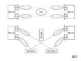
図2−図4は、空間多重を利用した通信方法の一例を示す。図2は、Multi−Array Spatial Aggregation(以下、「MA−SA」という)であり、2個のデバイスは、それぞれ2つのアレイアンテナを備え、該2つのアレイアンテナを用いて2ストリームの伝搬路を設定する。これによって、2個のデバイス間で、2倍の伝送容量を得る。図3は、空間多重を利用した通信方法の一例として、Spatial Aggregation(以下、「SA」という)を示す。図3は、図2に示される空間多重を利用した通信方法のサブセットである。図4は、図2に示される空間多重を利用した通信方法のサブセットであり、2個のデバイス間の伝送路に反射板を用いたものである。<Communication method>
Here, communication method candidates to be applied to the wireless communication system according to the present embodiment will be described.
<Spatial multiplexing>
2 to 4 show an example of a communication method using spatial multiplexing. FIG. 2 shows Multi-Array Spatial Aggregation (hereinafter referred to as “MA-SA”). Each of the two devices includes two array antennas, and the two array antennas are used to transmit two streams. Set. As a result, a double transmission capacity is obtained between the two devices. FIG. 3 shows Spatial Aggregation (hereinafter referred to as “SA”) as an example of a communication method using spatial multiplexing. FIG. 3 is a subset of the communication method using the spatial multiplexing shown in FIG. FIG. 4 is a subset of the communication method using spatial multiplexing shown in FIG. 2, and uses a reflector in the transmission path between two devices.
<ビームフォーミング>
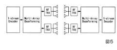
図5は、ビームフォーミングを利用した通信方法の一例を示す。図5は、マルチアレイビームフォーミング(Multi−Array Beamforming(以下、「MA−BF」という))であり、2つのアレイアンテナを合わせてビームフォーミングに用いる。これによって、単一アレイの場合と比べてアンテナゲインを得ることができる。<Beam forming>
FIG. 5 shows an example of a communication method using beamforming. FIG. 5 shows multi-array beamforming (hereinafter referred to as “MA-BF”), and two array antennas are used together for beamforming. Thereby, the antenna gain can be obtained as compared with the case of a single array.
<空間ダイバシティ>
図6は、空間ダイバシティを利用した通信方法の一例を示す。図6は、マルチアレイによる空間ダイバシティ(Multi−Array Space Diversity(以下、「MA−SD」という))である。
本実施形態に係る無線通信システムでは、通信方法の一例として、MA−SA、MA−SDを適用する場合について説明を続ける。しかし、無線通信システムに、MA−SA、MA−SD以外の通信方法が適用されてもよい。<Space diversity>
FIG. 6 shows an example of a communication method using space diversity. FIG. 6 shows multi-array space diversity (hereinafter referred to as “MA-SD”).
In the wireless communication system according to the present embodiment, description will be continued for the case where MA-SA and MA-SD are applied as an example of a communication method. However, communication methods other than MA-SA and MA-SD may be applied to the wireless communication system.
<指向性の調整を開始する処理>
無線基地局装置100は、該無線基地局装置100が備える複数のアレイアンテナの各々から、指向性の調整を開始する信号(以下、「指向性調整開始信号」という)を無指向性の指向性パターンで順次送信する。
端末装置200は、無線基地局装置100が送信する指向性調整開始信号を受信すると、該指向性調整開始信号の受信強度もしくは受信強度対雑音比などの信号品質(以下、「信号品質」という)等を測定することによって受信状況を取得し、無線基地局装置100が指向性調整開始信号を送信しているアレイアンテナを識別する情報と紐付けて保持する。端末装置200は、指向性調整開始信号に対する応答信号を無線基地局装置100へフィードバックする。該応答信号には、無線基地局装置100が備える複数のアレイアンテナを識別する情報の各々について、該アレイアンテナによって送信された指向性調整開始信号の受信状況が付帯される。<Process for starting directivity adjustment>
The radio
When the
<指向性を調整する処理>
無線基地局装置100は、端末装置200によって送信される指向性調整開始信号に対する応答信号を受信すると、複数のアレイアンテナの各々から指向性ビームを形成して、指向性を調整するための信号(以下、「指向性調整信号」という)を送信する。端末装置200は、無線基地局装置100が送信する指向性調整信号を受信し、該指向性調整信号の受信強度もしくは信号品質等を測定する。端末装置200は、該指向性調整信号が送信された無線基地局装置100のアレイアンテナを識別する情報と、該指向性調整信号を識別する情報と紐付けて保持する。無線基地局装置100による指向性調整信号の送信が終了すると、端末装置200は、複数のアレイアンテナの各々から指向性ビームを形成して、指向性調整信号を送信する。無線基地局装置100は、端末装置200が送信する指向性調整信号を受信する。無線基地局装置100は、指向性調整信号の受信強度もしくは信号品質等を測定し、該指向性調整信号が送信されたアレイアンテナを識別する情報と、該指向性調整信号を識別する情報とを紐付けて保持する。<Process to adjust directivity>
When receiving a response signal to the directivity adjustment start signal transmitted by the
端末装置200による指向性調整信号の送信が終了すると、無線基地局装置100は、保持している指向性調整信号から最もよい受信強度もしくは信号品質の指向性調整信号をアレイアンテナを識別する情報毎に選択する。無線基地局装置100は、端末装置200によって送信された指向性調整信号に対するフィードバック信号(以下、「指向性調整フィードバック信号」という)を送信する。指向性調整フィードバック信号には、最もよい受信強度もしくは信号品質の指向性調整信号を識別する情報と、該指向性調整信号を送信した端末装置200のアレイアンテナを識別する情報とが含まれる。 When transmission of the directivity adjustment signal by the
端末装置200は、無線基地局装置100によって送信される指向性調整フィードバック信号を受信すると、保持している指向性調整信号から最もよい受信強度もしくは信号品質に対応する指向性調整信号を選択する。端末装置200は、無線基地局装置100によって送信される指向性調整フィードバック信号に含まれる最もよい受信強度もしくは信号品質の指向性調整信号を識別する情報と、該指向性調整信号を送信した端末装置200のアレイアンテナを識別する情報とに基づいて、各アレイアンテナについて指向性調整フィードバック信号を送信する指向性パターンを求め、設定する。 When the
無線基地局装置100は、端末装置200によって送信される指向性調整フィードバック信号を受信すると、該指向性調整フィードバック信号に含まれる最もよい受信強度、もしくは信号品質の指向性調整信号を識別する情報と、該指向性調整信号を送信した無線基地局装置100のアレイアンテナを識別する情報とに基づいて、各アレイアンテナについて指向性調整信号に対する応答信号を送信する指向性パターンを求める。無線基地局装置100は、複数のアレイアンテナの各々について、求めた指向性パターンを設定する。無線基地局装置100は、複数のアレイアンテナの各々について求めた指向性パターンを設定すると、複数のアレイアンテナの各々から端末装置200へ指向性を確認するための信号(以下、「確認信号」という)を送信する。端末装置200は、無線基地局装置100によって送信される確認信号を受信すると、複数のアレイアンテナの各々から無線基地局装置100へ指向性を確認するための信号(以下、「確認信号」という)を送信する。これによって、無線基地局装置100と端末装置200との間で、アレイアンテナへの指向性の設定が終了する。
以下、無線基地局装置100、及び端末装置200の詳細について説明する。When the radio
Details of the radio
<無線基地局装置>
図7は、本実施形態に係る無線通信システムに含まれる無線基地局装置、及び端末装置の一例を示す。本実施形態に係る無線基地局装置100は、アレイアンテナ部102と、アレイアンテナ部104と、無線部106と、無線部108と、分波部110と、符号化・変調部112と、合成部114と、復調・復号部116と、メモリ部118と、中央制御部120と、アンテナ制御部122とを備える。<Radio base station equipment>
FIG. 7 shows an example of a radio base station apparatus and a terminal apparatus included in the radio communication system according to the present embodiment. The radio
符号化・変調部112は有線又は無線によってインターネット等のネットワーク50と接続され、復調・復号部116は有線又は無線によってネットワーク50と接続される。符号化・変調部112は、ネットワーク50を経由して供給されたデータに対して、符号化処理と変調処理とを行い、後段で無線信号形式に変換するのに適した形式の信号へ変換する。また、符号化・変調部112は、無線基地局装置100配下の無線ネットワークを管理するための管理信号や、制御するための制御信号に対して、符号化処理と変調処理とを行う。符号化・変調部112は、後段で無線信号形式に変換するのに適した形式の信号へ変換したデータ、管理信号、制御信号等を分波部110へ出力する。 The encoding /
分波部110は、符号化・変調部112と接続される。分波部110は、符号化・変調部112によって供給された信号をアレイアンテナの系統の数に分波する。図7に示される例ではアレイアンテナの系統数が2であるため、分波部110は無線の形式の信号を2系統に分波し、分波した信号をそれぞれ無線部106、及び無線部108へ出力する。この時、分波の方法は、端末装置200との通信方法に応じて、MA−SAをするためにそれぞれのアレイアンテナの系統に異なる信号を供給してよいし、MA−SDをするためにそれぞれのアレイアンテナの系統に同じ信号を供給してもよい。 The
無線部106、及び無線部108は、分波部110と接続される。無線部106、及び無線部108は、分波部110によって供給された信号を高周波信号へ変換する。そして、無線部106は高周波信号をアレイアンテナ部102へ出力し、無線部108は高周波信号をアレイアンテナ部104へ出力する。また、無線部106は、アレイアンテナ部102によって供給された高周波信号を合成部114に引き渡すのに適した周波数の形式の信号へ変換し、該形式の信号を合成部114へ出力する。無線部108は、アレイアンテナ部104によって供給された高周波信号を合成部114に引き渡すのに適した周波数の形式の信号へ変換し、該形式の信号を合成部114へ出力する。 The
アレイアンテナ部102は無線部106と接続され、アレイアンテナ部104は無線部108と接続される。アレイアンテナ部102は無線部106によって供給された高周波信号を送信し、アレイアンテナ部104は無線部108によって供給された高周波信号を送信する。また、アレイアンテナ部102は端末装置200によって送信された無線信号を受信し、該無線信号を無線部106へ出力する。アレイアンテナ部104は端末装置200によって送信された無線信号を受信し、該無線信号を無線部108へ出力する。
合成部114は、無線部106、及び無線部108と接続される。合成部114は、無線部106によって供給される信号と、無線部108によって供給される信号とを合成する。合成部114は、無線部106によって供給される信号と、無線部108によって供給される信号とを合成した合成信号を復調・復号部116へ出力する。この時、合成部114における合成の方法は、端末装置との通信方法に応じて行う。
復調・復号部116は、合成部114と接続される。復調・復号部116は、合成部114によって供給される合成信号の復調処理と復号処理とを行うことによって、端末装置200が送信するデジタル信号を復元する。復調・復号部116は、復元したデジタル信号をネットワーク50や、中央制御部120等へ出力する。The combining
The demodulation / decoding unit 116 is connected to the
アンテナ制御部122は、アレイアンテナ部102、及びアレイアンテナ部104と接続される。アンテナ制御部122は、通信相手の端末装置200との調整結果に応じて、アレイアンテナ部102、及びアレイアンテナ部104が送信する指向性ビームの方向等を制御する。また、アンテナ制御部122は、通信相手の端末装置200との調整結果に応じて、アレイアンテナ部102、及びアレイアンテナ部104の方向を制御して端末装置200が送信する信号を受信する。 The
中央制御部120は、符号化・変調部112、復調・復号部116、無線部106、無線部108、及びアンテナ制御部122と接続される。中央制御部120は、無線基地局装置100の符号化・変調部112、復調・復号部116、無線部106、及び無線部108を制御する。また、中央制御部120は、アンテナ制御部122にアレイアンテナ部102、及びアレイアンテナ部104を制御するための制御信号を出力する。中央制御部120は、ビーコン信号を生成し、符号化・変調部112へ出力する。符号化・変調部112は、ビーコン信号の符号化処理と変調処理とを行う。 The
また、中央制御部120は、端末装置200が送信するプローブリクエストが復調・復号部116から供給された場合、該プローブリクエストに対するプローブレスポンスを生成し、符号化・変調部112へ出力する。符号化・変調部112は、プローブレスポンスの符号化処理と変調処理とを行う。例えば、中央制御部120は、無線基地局装置100のアレイ通信能力情報を含むビーコン信号を生成し、符号化・変調部112へ出力する。また、例えば、中央制御部120は、無線基地局装置のアレイ通信能力情報を含むプローブレスポンスを生成し、符号化・変調部112へ出力する。 Further, when a probe request transmitted from the
図8は、アレイ通信能力情報の一例を示す。アレイ通信能力情報は、例えば、MACフレームで実現され、情報を識別する情報(情報ID)と、アレイアンテナ(部)の数を表す情報(アレイ数情報)と、適用可能な通信方法を表す情報(通信方法情報)とを含む。ここでは、情報IDにはアレイ通信能力情報を表す情報が付帯され、アレイ数情報には無線基地局装置100の備えるアレイアンテナの数である「2」が付帯される。また、通信方法情報には、MA−SAを表す情報、及びMA−SDを表す情報が付帯される。また、中央制御部120は、指向性調整開始信号を生成し、符号化・変調部112へ出力する。 FIG. 8 shows an example of array communication capability information. The array communication capability information is realized by, for example, a MAC frame, information (information ID) for identifying information, information indicating the number of array antennas (units) (array number information), and information indicating an applicable communication method (Communication method information). Here, information representing array communication capability information is attached to the information ID, and “2” that is the number of array antennas included in the radio
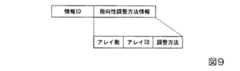
図9は、指向性調整開始信号の一例を示す。指向性調整開始信号は、情報IDと、指向性を調整する方法を表す情報(指向性調整方法情報)とが含まれる。さらに、指向性調整方法情報は、アレイアンテナの数を表す情報(アレイ数)と、アレイアンテナを識別する情報(アレイID)と、調整方法を表す情報(調整方法)とを含む。ここでは、情報を識別する情報には指向性調整開始信号を表す情報が付帯される。 FIG. 9 shows an example of the directivity adjustment start signal. The directivity adjustment start signal includes an information ID and information indicating a method for adjusting directivity (directivity adjustment method information). Furthermore, the directivity adjustment method information includes information indicating the number of array antennas (number of arrays), information for identifying the array antenna (array ID), and information indicating the adjustment method (adjustment method). Here, information indicating the directivity adjustment start signal is attached to the information for identifying the information.
アレイ数には無線基地局装置100の備えるアレイアンテナの数である「2」が付帯される。アレイIDには、各アレイアンテナから指向性開始調整信号を送信するときに「1」又は「2」が付帯される。ここで、「1」はアレイアンテナ部102を示し、「2」はアレイアンテナ部104を示す。以下、同様である。調整方法は、アレイアンテナ部の数を表す情報と指向性調整開始信号を送信しているアレイアンテナを識別する情報とを等しくすることによって、無線基地局装置100が指向性調整開始信号の送信を終了すること等を表す情報である。つまり、ここでは、アレイアンテナ部の数である「2」と、指向性調整開始信号を送信しているアレイアンテナ部を識別する情報「2」となった場合に終了する。 “2” that is the number of array antennas included in the radio
また、中央制御部120は、指向性調整信号を生成し、符号化・変調部112へ出力する。
図10は、指向性調整信号の一例を示す。指向性調整信号は、情報IDと、アレイIDと、指向性ビームを識別する情報(ビームID)と、該アレイアンテナによって送信する指向性ビームの残りの数を表す情報(残りビーム数)とを含む。ここでは、情報IDには指向性調整信号を表す情報が付帯される。アレイIDには、各アレイアンテナから指向性開始調整信号を送信するときに「1」又は「2」がセットされる。ビームIDには指向性調整信号を送信するのに使用する指向性ビームを識別する情報を指定する。残りビーム数は、アレイアンテナによって送信する指向性ビームの総数から該アレイアンテナによって既に送信した指向性ビームの数を減算した値によって表される。例えば、アレイアンテナ部102が、M(Mは、M>1の整数)種類の指向性ビームを形成する場合について説明する。アレイアンテナ部102が、ビームIDが1からMまでの順に指向性ビームを用いて指向性調整信号を送信(セクタースウィーブ)している。この場合、アレイアンテナによって送信する指向性ビームの残りの数を表す情報は、「M−1」、「M−2」、・・・、1、0の順に指定される。The
FIG. 10 shows an example of the directivity adjustment signal. The directivity adjustment signal includes an information ID, an array ID, information for identifying a directional beam (beam ID), and information indicating the remaining number of directional beams transmitted by the array antenna (the number of remaining beams). Including. Here, information representing the directivity adjustment signal is attached to the information ID. The array ID is set to “1” or “2” when a directivity start adjustment signal is transmitted from each array antenna. In the beam ID, information for identifying a directional beam used for transmitting a directivity adjustment signal is designated. The number of remaining beams is represented by a value obtained by subtracting the number of directional beams already transmitted by the array antenna from the total number of directional beams transmitted by the array antenna. For example, a case where the
また、中央制御部120は、指向性調整フィードバック信号を生成し、符号化・変調部112へ出力する。
図11は、指向性調整フィードバック信号の一例を示す。指向性調整フィードバック信号は、情報IDと、アレイIDと、最もよい受信強度もしくは信号品質の指向性調整信号を表す情報(ベストビーム情報)とを含む。さらに、ベストビーム情報は、アレイIDとビームIDとを含む。
メモリ部118は、中央制御部120と接続される。メモリ部118は、通信相手の端末装置毎に使用するアレイアンテナ部102、及びアレイアンテナ部104の指向性を表す情報等の制御情報を記憶する。図7に戻り説明を続ける。The
FIG. 11 shows an example of the directivity adjustment feedback signal. The directivity adjustment feedback signal includes an information ID, an array ID, and information (best beam information) representing the directivity adjustment signal having the best reception strength or signal quality. Furthermore, the best beam information includes an array ID and a beam ID.
The
<端末装置>
本実施形態に係る端末装置200は、アレイアンテナ部202と、アレイアンテナ部204と、無線部206と、無線部208と、分波部210と、符号化・変調部212と、合成部214と、復調・復号部216と、メモリ部218と、中央制御部220と、アンテナ制御部222とを備える。
符号化・変調部212は、送信データに対して、符号化処理と変調処理とを行い、後段で無線信号形式に変換するのに適した信号へ変換する。符号化・変調部212は、該形式の信号へ変換した送信データを分波部210へ出力する。<Terminal device>
The
The encoding /
分波部210は、符号化・変調部212と接続される。分波部210は、符号化・変調部212によって供給された無線の形式の送信データをアレイアンテナの系統の数に分波する。図7に示される例ではアレイアンテナの系統数が2であるため、分波部210は無線の形式の送信データを2系統に分波し、分波した無線の形式の送信データをそれぞれ無線部206、及び無線部208へ出力する。この時、分波の方法は、無線基地局装置100との通信方法に応じて、MA−SAをするためにそれぞれのアレイアンテナの系統に異なる信号を供給してよいし、MA−SDをするためにそれぞれのアレイアンテナの系統に同じ信号を供給してもよい。 The
無線部206、及び無線部208は、分波部210と接続される。無線部206、及び無線部208は、分波部210によって供給された形式の送信データを高周波信号へ変換する。そして、無線部206は該高周波信号をアレイアンテナ部202へ出力し、無線部208は該高周波信号をアレイアンテナ部204へ出力する。また、無線部206は、アレイアンテナ部202によって供給された高周波信号を無線の形式の信号へ変換し、該無線の形式の信号を合成部214へ出力する。無線部208は、アレイアンテナ部204によって供給された高周波信号を合成部214に引き渡すのに適した周波数の形式の信号へ変換し、該形式の信号を合成部214へ出力する。
アレイアンテナ部202は無線部206と接続され、アレイアンテナ部204は無線部208と接続される。アレイアンテナ部202は無線部206によって供給された高周波信号を送信し、アレイアンテナ部204は無線部208によって供給された高周波信号を送信する。また、アレイアンテナ部202は無線基地局装置100が送信した無線信号を受信し、該無線信号を無線部206へ出力する。アレイアンテナ部204は無線基地局装置100が送信した無線信号を受信し、該無線信号を無線部208へ出力する。
合成部214は、無線部206、及び無線部208と接続される。合成部214は、無線部206によって供給される形式の信号と、無線部208によって供給される形式の信号とを合成する。合成部214は、無線部206によって供給される無線の形式の信号と、無線部208によって供給される無線の形式の信号とを合成した合成信号を復調・復号部216へ出力する。この時、合成部214における合成の方法は、無線基地局装置100との通信方法に応じて行う。
復調・復号部216は、合成部214と接続される。復調・復号部216は、合成部214によって供給される合成信号の復調処理と復号処理とを行う。復調・復号部216は、合成部214によって復調処理と復号処理とが行われることによって得られるデータを中央制御部220等へ出力する、もしくは、端末装置200の後段に接続されるPCなどに出力することとしてもよい。The combining
The demodulation /
アンテナ制御部222は、アレイアンテナ部202、及びアレイアンテナ部204と接続される。アンテナ制御部222は、通信相手の無線基地局装置100との調整結果に応じてアレイアンテナ部202、及びアレイアンテナ部204が送信する指向性ビームの方向等を制御する。また、アンテナ制御部222は、通信相手の無線基地局装置100との調整結果に応じて、アレイアンテナ部202及びアレイアンテナ部204の方向等を制御して無線基地局装置100が送信する信号を受信する。 The
中央制御部220は、符号化・変調部212、復調・復号部216、無線部206、無線部208、及びアンテナ制御部222と接続される。中央制御部220は、端末装置200の符号化・変調部212、復調・復号部216、無線部206、無線部208、及びアンテナ制御部222を制御する。中央制御部220は、無線基地局装置100の探索のためにプローブリクエストを生成し、符号化・変調部212へ出力する。例えば、中央制御部220は、端末装置200のアレイ通信能力情報を含むプローブリクエストを生成し、符号化・変調部212へ出力する。アレイ通信能力情報の一例は、図8を適用できる。
また、中央制御部220は、指向性調整開始信号を生成し、符号化・変調部212へ出力する。指向性調整開始信号の一例は、図9を適用できる。また、中央制御部220は、指向性調整開始信号に対する応答信号(指向性調整応答信号)を生成し、符号化・変調部212へ出力する。The
The
図12は、指向性調整応答信号の一例を示す。指向性調整応答信号は、情報IDと、指向性調整方法応答情報(指向性調整方法応答信号)とが含まれる。さらに、指向性調整方法応答信号は、アレイ数と、アレイIDと、無線基地局装置100によって送信された指向性調整開始信号の受信状況を示すフィードバック情報(受信状況FB)とが含まれる。さらに、フィードバック情報には、フィードバックされる受信状況の数を表す情報(FB数)と、受信状況を表す情報(FB情報)を含む。また、中央制御部220は、指向性調整信号を生成し、符号化・変調部212へ出力する。指向性調整信号の一例は、図10を適用できる。 FIG. 12 shows an example of the directivity adjustment response signal. The directivity adjustment response signal includes an information ID and directivity adjustment method response information (directivity adjustment method response signal). Furthermore, the directivity adjustment method response signal includes the number of arrays, the array ID, and feedback information (reception status FB) indicating the reception status of the directivity adjustment start signal transmitted by the radio
また、中央制御部220は、指向性調整フィードバック信号を生成し、符号化・変調部212へ出力する。指向性調整フィードバック信号の一例は、図11を適用できる。
メモリ部218は、中央制御部220と接続される。メモリ部218は、通信相手の無線基地局装置100毎に使用するアレイアンテナ部202、及びアレイアンテナ部204の指向性を表す情報等の制御情報を記憶する。The
The
<無線通信システムの動作>
無線通信システムの動作について説明する。ここでは、一例として、無線基地局装置100はM(Mは、M>1の整数)本の指向性ビームを送信でき、端末装置200はN(Nは、N>0の整数)本の指向性ビームをそれぞれのアレイアンテナ部から送信できる場合について説明する。<Operation of wireless communication system>
An operation of the wireless communication system will be described. Here, as an example, radio
<装置の検出から通信方法を決定するまでの動作>
無線基地局装置100、及び端末装置200は、無線接続に先立って、お互いの存在を検出する。例えば、端末装置200は、プローブリクエストに端末装置200のアレイ通信能力情報を含めて送信する。無線基地局装置100は、該プローブリクエストを受信することによって端末装置200を検出する。そして、無線基地局装置100は、プローブレスポンスに無線基地局装置100のアレイ通信能力情報を含めて送信(ユニキャスト)する。
端末装置200は、該プローブレスポンスを受信することによって無線基地局装置100を検出する。無線基地局装置100の中央制御部120は、端末装置200を検出すると、無線基地局装置100のアレイ通信能力情報と端末装置200のアレイ通信能力情報とに基づいて、端末装置200との間で使用する通信方法を決定する。<Operation from device detection to communication method determination>
The radio
The
また、無線基地局装置100は、ビーコン信号に無線基地局装置100のアレイ通信能力情報を含めて報知(ブロードキャスト)する。例えば、無線基地局装置100は、ビーコン信号のフレームボディに無線基地局装置100のアレイ通信能力情報を含める。 Also, the radio
端末装置200は、該ビーコン信号を受信することによって無線基地局装置100を検出してもよい。そして、ビーコン信号を受信した端末装置200は、ビーコン信号に対する応答信号に端末装置200のアレイ通信能力情報を含めて送信する。無線基地局装置100は、該応答信号を受信することによって端末装置200を検出する。 The
図13は、本実施形態に係る無線通信システムの動作を示す図である。
<指向性の調整を開始する処理>
ステップS1302では、無線基地局装置100は、中央制御部120において指向性調整開始信号を生成する。無線基地局装置100は、該指向性調整開始信号を、符号化・変調部112で処理し、分波部110から無線部106に出力し、無線部106において高周波信号へ変換し、アレイアンテナ部102から無指向性の指向性パターン(準オムニ)で送信する。
端末装置200は、無線基地局装置100によって送信される指向性調整開始信号をそれぞれのアレイアンテナ部202および204にて無指向性の指向性パターン(準オムニ)で受信すると、該指向性調整開始信号の受信強度、もしくは信号品質等を測定することによって受信状況を取得し、指向性調整開始信号を送信しているアレイアンテナ部102を識別する情報と紐付けて保持する。FIG. 13 is a diagram illustrating an operation of the wireless communication system according to the present embodiment.
<Process for starting directivity adjustment>
In step S1302, the radio
When the
ステップS1304では、無線基地局装置100は、中央制御部120において指向性調整開始信号を生成する。無線基地局装置100は、該指向性調整開始信号を、符号化・変調部112で処理し、分波部110から無線部108に出力し、無線部108において高周波信号へ変換し、アレイアンテナ部104から無指向性の指向性パターンで送信する。
端末装置200は、無線基地局装置100によって送信される指向性調整開始信号をそれぞれのアレイアンテナ部202および204にて無指向性の指向性パターンで受信すると、該指向性調整開始信号の受信強度、もしくは信号品質等を測定することによって受信状況を取得し、指向性調整開始信号を送信しているアレイアンテナ部104を識別する情報と紐付けて保持する。端末装置200は、指向性調整開始信号に付帯されるアレイアンテナの数を表す情報と、アレイアンテナを識別する情報とが等しいため、該指向性調整開始信号より後に指向性調整開始信号が送信されないと判断する。In step S1304, the radio
When the
ステップS1306では、端末装置200は、中央制御部220において指向性調整応答信号を生成する。端末装置200は、該指向性調整応答信号を、符号化・変調部212で処理し、分波部210から無線部206に出力し、無線部206において高周波信号へ変換し、アレイアンテナ部202から無指向性の指向性パターンで、無線基地局装置100へフィードバックする。
無線基地局装置100は、端末装置200のアレイアンテナ部202によって送信された指向性調整応答信号を受信する。これによって、無線基地局装置100は、アレイアンテナ部102から無指向性の指向性パターンで送信を行った場合の端末装置200における受信状況の確認ができる。In step S1306, the
The radio
ステップS1308では、端末装置200は、中央制御部220において指向性調整応答信号を生成する。端末装置200は、該指向性調整応答信号を、符号化・変調部212で処理し、分波部210から無線部208に出力し、無線部208において高周波信号へ変換し、アレイアンテナ部204から無指向性の指向性パターンで、無線基地局装置100へフィードバックする。
無線基地局装置100は、端末装置200のアレイアンテナ部204によって送信された指向性調整開始応答信号を受信する。これによって、無線基地局装置100は、アレイアンテナ部104から無指向性の指向性パターンで送信を行った場合の端末装置200における受信状況の確認ができる。In step S1308, the
The radio
<指向性を調整する処理>
本実施形態に係る無線通信システムは、2つのアレイアンテナ部を備える無線基地局装置と、2つのアレイアンテナ部を備える端末装置とを備える。このため、2つのアレイアンテナ部と2つのアレイアンテナ部との間、つまり2×2の調整処理を行う。
ステップS1310では、無線基地局装置100は、中央制御部120において指向性調整信号を生成する。無線基地局装置100は、該指向性調整信号を、符号化・変調部112で処理し、分波部110によって無線部106に出力し、無線部106において高周波信号へ変換し、アレイアンテナ部102から指向性が異なるM本の指向性ビームをセクタースウィープすることによって順次送信する。<Process to adjust directivity>
The radio communication system according to the present embodiment includes a radio base station apparatus including two array antenna units and a terminal apparatus including two array antenna units. For this reason, an adjustment process of 2 × 2 is performed between the two array antenna units and the two array antenna units.
In step S1310, the radio
端末装置200は、アレイアンテナ部202、及びアレイアンテナ部204において、無線基地局装置100によって送信される指向性調整信号を無指向性の指向性パターンで受信する。端末装置200は、アンテナ制御部222が無指向性の指向性パターンとしたアレイアンテナ部202、及びアレイアンテナ部204によってそれぞれの指向性調整信号の受信強度、もしくは信号品質を測定する。アンテナ制御部222は、それぞれの指向性調整信号の受信強度、もしくは信号品質を表す情報を中央制御部220へ出力する。中央制御部220は、アンテナ制御部222によって供給されたそれぞれの指向性調整信号の受信強度、もしくは信号品質を表す情報を、該指向性調整信号が送信された無線基地局装置100におけるアレイアンテナを識別する情報と、該指向性調整信号を識別する情報と紐付けてメモリ部218へ保持する。 The
ステップS1312では、無線基地局装置100は、中央制御部120において指向性調整信号を生成する。無線基地局装置100は、該指向性調整信号を、符号化・変調部112で処理し、分波部110によって無線部108に出力し、無線部108において高周波信号へ変換し、アレイアンテナ部104から指向性が異なるM本の指向性ビームをセクタースウィープすることによって順次送信する。 In step S1312, the radio
端末装置200は、アレイアンテナ部202、及びアレイアンテナ部204において、無線基地局装置100によって送信される指向性調整信号を無指向性の指向性パターンで受信する。端末装置200は、アンテナ制御部222が無指向性の指向性パターンとしたアレイアンテナ部202、及びアレイアンテナ部204によってそれぞれの指向性調整信号の受信強度、もしくは信号品質を測定する。アンテナ制御部222は、それぞれの指向性調整信号の受信強度、もしくは信号品質を表す情報を中央制御部220へ出力する。中央制御部220は、アンテナ制御部222によって供給されたそれぞれの指向性調整信号の受信強度、もしくは信号品質を表す情報を、該指向性調整信号が送信された無線基地局装置100におけるアレイアンテナを識別する情報と、該指向性調整信号を識別する情報と紐付けてメモリ部218へ保持する。 The
ステップS1314では、端末装置200は、中央制御部220において指向性調整信号を生成する。端末装置200は、該指向性調整信号を、符号化・変調部212で処理し、分波部210によって無線部206に出力し、無線部206において高周波信号へ変換し、アレイアンテナ部202から指向性が異なるN本の指向性ビームをセクタースウィープすることによって順次送信する。 In step S1314, the
無線基地局装置100は、アレイアンテナ部102、及びアレイアンテナ部104において、端末装置200によって送信される指向性調整信号を無指向性の指向性パターンで受信する。無線基地局装置100は、アンテナ制御部122が無指向性の指向性パターンとしたアレイアンテナ部102、及びアレイアンテナ部104によってそれぞれの指向性調整信号の受信強度、もしくは信号品質を測定する。アンテナ制御部122は、それぞれの指向性調整信号の受信強度、もしくは信号品質を表す情報を中央制御部120へ出力する。中央制御部120は、アンテナ制御部122によって供給されたそれぞれの指向性調整信号の受信強度、もしくは信号品質を表す情報を、該指向性調整信号が送信された端末装置200におけるアレイアンテナを識別する情報と、該指向性調整信号を識別する情報と紐付けてメモリ部118へ保持する。 The radio
ステップS1316では、端末装置200は、中央制御部220において指向性調整信号を生成する。端末装置200は、該指向性調整信号を、符号化・変調部212で処理し、分波部210によって無線部208に出力し、無線部208において高周波信号へ変換し、アレイアンテナ部204から指向性が異なるN本の指向性ビームをセクタースウィープすることによって順次送信する。 In step S1316, the
無線基地局装置100は、アレイアンテナ部102、及びアレイアンテナ部104において、端末装置200によって送信される指向性調整信号を無指向性の指向性パターンで受信する。無線基地局装置100は、アンテナ制御部122が無指向性の指向性パターンとしたアレイアンテナ部102、及びアレイアンテナ部104によってそれぞれの指向性調整信号の受信強度、もしくは信号品質を測定する。アンテナ制御部122は、指向性調整信号の受信強度を表す情報を中央制御部120へ出力する。中央制御部120は、アンテナ制御部122によって供給された指向性調整信号の受信強度を表す情報を、該指向性調整信号が送信された端末装置200におけるアレイアンテナを識別する情報と、該指向性調整信号を識別する情報と紐付けてメモリ部118へ保持する。 The radio
ステップS1318では、無線基地局装置100は、中央制御部120においてメモリ部118に保持している端末装置200におけるアレイアンテナ部202を識別する情報に紐付けられた指向性調整信号から最もよい受信強度もしくは信号品質の指向性調整信号を選択する。そして、無線基地局装置100は、中央制御部120において指向性調整フィードバック信号を生成する。
無線基地局装置100は、該指向性調整フィードバック信号を、符号化・変調部112で処理し、分波部110から無線部106に出力し、無線部106において高周波信号へ変換し、アレイアンテナ部102から無指向性の指向性パターンで送信する。端末装置200は、アレイアンテナ部102、及びアレイアンテナ部104において、無線基地局装置100によって送信される指向性調整フィードバック信号を無指向性の指向性パターンで受信する。端末装置200は、アンテナ制御部222において該指向性調整フィードバック情報に付帯される指向性を識別する情報に基づいて、アレイアンテナ部202から送信する指向性ビームの指向性を設定する。これによって、端末装置200は、アレイアンテナ部202から無線基地局装置100へ、指向性ビームを送信するのに使用する指向性を設定できる。In step S1318, the radio
The radio
ステップS1320では、無線基地局装置100は、中央制御部120においてメモリ部118に保持している端末装置200におけるアレイアンテナ部204を識別する情報に紐付けられた指向性調整信号から最もよい受信強度、もしくは信号品質の指向性調整信号を選択する。そして、無線基地局装置100は、中央制御部120において指向性調整フィードバック信号を生成する。無線基地局装置100は、該指向性調整フィードバック信号を、符号化・変調部112で処理し、分波部110から無線部108に出力し、無線部108において高周波信号へ変換し、アレイアンテナ部104から無指向性の指向性パターンで送信する。
端末装置200は、アレイアンテナ部102、及びアレイアンテナ部104において、無線基地局装置100によって送信される指向性調整フィードバック信号を無指向性の指向性パターンで受信する。端末装置200は、アンテナ制御部222において該指向性調整フィードバック情報に付帯される指向性を識別する情報に基づいて、アレイアンテナ部204から送信する指向性ビームの指向性を設定する。これによって、端末装置200は、アレイアンテナ部204から無線基地局装置100へ、指向性ビームを送信するのに使用する指向性を設定できる。In step S1320, the radio
The
ステップS1322では、端末装置200は、中央制御部220においてメモリ部218に保持している無線基地局装置100におけるアレイアンテナ部102識別する情報に紐付けられた指向性調整信号から最もよい受信強度、もしくは信号品質の指向性調整信号を選択する。そして、端末装置200は、中央制御部220において指向性調整フィードバック信号を生成する。端末装置200は、該指向性調整フィードバック信号を、符号化・変調部212で処理し、分波部210から無線部206に出力し、無線部206において高周波信号へ変換し、アレイアンテナ部202からステップS1318で設定した指向性パターンで送信する。
無線基地局装置100は、アレイアンテナ部202、及びアレイアンテナ部204において、端末装置200によって送信される指向性調整フィードバック信号を無指向性の指向性パターンで受信する。無線基地局装置100は、アンテナ制御部122において該指向性調整フィードバック情報に付帯される指向性を識別する情報に基づいて、アレイアンテナ部102から送信する指向性ビームの指向性を設定する。これによって、無線基地局装置100は、アレイアンテナ部102から端末装置200へ、指向性ビームを送信するのに使用する指向性を設定できる。In step S1322, the
The radio
ステップS1324では、端末装置200は、中央制御部220においてメモリ部218に保持している無線基地局装置100におけるアレイアンテナ部104を識別する情報に紐付けられた指向性調整信号から最もよい受信強度、もしくは信号品質の指向性調整信号を選択する。そして、端末装置200は、中央制御部220において指向性調整フィードバック信号を生成する。端末装置200は、該指向性調整フィードバック信号を、符号化・変調部212で処理し、分波部210から無線部206に出力し、無線部206において高周波信号へ変換し、アレイアンテナ部202からステップS1320において設定した指向性パターンで送信する。
無線基地局装置100は、アレイアンテナ部202、及びアレイアンテナ部204において、端末装置200によって送信される指向性調整フィードバック信号を無指向性の指向性パターンで受信する。無線基地局装置100は、アンテナ制御部122において該指向性調整フィードバック情報に付帯される指向性を識別する情報に基づいて、アレイアンテナ部104から送信する指向性ビームの指向性を設定する。これによって、無線基地局装置100は、アレイアンテナ部104から端末装置200へ、指向性ビームを送信するのに使用する指向性を設定できる。In step S1324, the
The radio
ステップS1326では、無線基地局装置100は、中央制御部120において確認信号を生成する。無線基地局装置100は、該確認信号を、符号化・変調部112で処理し、分波部110から無線部106、及び無線部108へ出力し、無線部106、及び無線部108において高周波信号へ変換し、アレイアンテナ部102からステップS1322において設定した指向性パターンで送信するとともに、アレイアンテナ部104からステップS1324において設定した指向性パターンで送信する。端末装置200は、無線基地局装置100によって送信された確認信号を受信する。 In step S1326, the radio
ステップS1328では、端末装置200は、中央制御部220において確認信号を生成する。端末装置200は、該確認信号を、符号化・変調部112で処理し、分波部210によって無線部206、及び無線部208へ出力し、無線部206、及び無線部208において高周波信号へ変換し、アレイアンテナ部202からステップS1324において設定した指向性パターンで送信するとともに、アレイアンテナ部204からステップS1326において設定した指向性パターンで送信する。無線基地局装置100は、端末装置200によって送信された確認信号を受信する。これによって、無線基地局装置100と、端末装置200との間で、アレイアンテナ部の指向性の調整が終了する。 In step S1328, the
<指向性の設定例(その1)>
図14は、本実施形態に係る無線通信システムにおいて、アレイアンテナ部の指向性の調整によって設定された指向性ビームの一例を示す。図14には、一例として、3個のアレイアンテナ部302、アレイアンテナ部304、及びアレイアンテナ部306を有する無線基地局装置と、1個のアレイアンテナ部402を有する端末装置との間で指向性の調整が行われた場合について示す。図14においては、アレイアンテナ部を示し、アレイアンテナ部以外は省略される。アレイアンテナ部302は指向性ビームを識別する情報が「3」で表される指向性ビーム352を出力し、アレイアンテナ部304は指向性ビームを識別する情報が「15」で表される指向性ビーム354を出力し、アレイアンテナ部306は指向性ビームを識別する情報が「22」で表される指向性ビーム356を出力する。<Directivity setting example (1)>
FIG. 14 shows an example of a directional beam set by adjusting the directivity of the array antenna unit in the wireless communication system according to the present embodiment. In FIG. 14, as an example, directing between a radio base station apparatus having three
無線基地局装置によって指向性が設定されるのに先立って、端末装置は、無線基地局装置のアレイアンテナ部302、アレイアンテナ部304、及びアレイアンテナ部306の各々から送信される指向性調整信号から最もよい受信強度、もしくは信号品質の指向性調整信号をアレイアンテナ部毎に選択する。そして、端末装置は、最もよい受信強度、もしくは信号品質の指向性調整信号の指向性を識別する情報を付帯した指向性調整フィードバック信号を送信する。ここでは、端末装置は、アレイアンテナ部302によって送信された指向性調整信号に対する指向性調整フィードバック信号に最もよい受信強度、または信号品質の指向性調整信号の指向性を識別する情報として「3」を付帯する。また、端末装置は、アレイアンテナ部304によって送信された指向性調整信号に対する指向性調整フィードバック信号に最もよい受信強度、もしくは信号品質の指向性調整信号の指向性を識別する情報として「15」を付帯する。また、端末装置は、アレイアンテナ部306によって送信された指向性調整信号に対する指向性調整フィードバック信号に最もよい受信強度、もしくは信号品質の指向性調整信号の指向性を識別する情報として「22」を付帯する。 Prior to setting the directivity by the radio base station apparatus, the terminal apparatus transmits a directivity adjustment signal transmitted from each of the
図14には、アレイアンテナ部302によって送信される指向性ビームと、アレイアンテナ部304によって送信される指向性ビームと、アレイアンテナ部306によって送信される指向性ビームの各々が異なる方向を向いているが、最終的には端末装置200のアレイアンテナ部402で受信される。ここでは、アレイアンテナ部302によって送信される指向性ビーム、及びアレイアンテナ部306によって送信される指向性ビームが反射することによって、端末装置に受信されたと想定される。 In FIG. 14, the directional beam transmitted by the
一方、端末装置のアレイアンテナ部402は、指向性ビームを識別する情報が「3」で表される指向性ビーム452を受信する。指向性ビーム452は、無線基地局装置によって送信される指向性ビーム352から指向性ビーム356よりも幅が広い。一般に、端末装置のアンテナの実装面積は、無線基地局装置のアンテナの実装面積よりも小さいため、端末装置の備えるアンテナの素子数は少なくなる。このため、無線基地局装置と比較して、端末装置は指向性ビームの放射角をあまり狭く集中させることができない。 On the other hand, the
しかし、端末装置は、指向性ビームの正対方向からある程度の角度をもって入射する反射波も受信することができる。端末装置は、伝搬路が車両や人物等の遮蔽物によって遮られない場合、無線基地局装置のアレイアンテナ部304によって送信された直接波を受信できる。しかし、遮蔽物によって遮られる場合に直接波を端末装置が受信できない場合であっても、ガラス等の反射物によって反射した経路を通るアレイアンテナ部302及びアレイアンテナ部306によって送信された指向性ビームを端末装置が受信できる場合がある。直接波の伝搬路が遮られた場合であっても、反射波を受信することによって、直接波と同じ信号を端末装置が受信できるようにするため、無線基地局装置は、複数のアレイアンテナ部の各々から同一の信号を同一の周波数で送信する。
端末装置は、複数の異なる経路を経由して送信された複数の信号を受信した場合、マルチパス干渉を補償して復号することによって所望のデータを得ることができる。例えば、無線基地局装置からOFDM信号を送信することによって、複数経路を経由して到来する同一の信号対して、マルチパス干渉を補償して復号することが容易にできる。However, the terminal device can also receive a reflected wave incident at a certain angle from the direction of the directivity beam. The terminal device can receive a direct wave transmitted by the
When receiving a plurality of signals transmitted via a plurality of different paths, the terminal device can obtain desired data by compensating for and decoding multipath interference. For example, by transmitting an OFDM signal from a radio base station apparatus, it is possible to easily decode the same signal that arrives via a plurality of paths while compensating for multipath interference.
<指向性の設定例(その2)>
図15は、2個のアレイアンテナ部の各々について指向性を設定して通信を開始したが、1個のアレイアンテナ部によって送信される指向性ビームが障害物によって遮蔽された場合を示す。この場合、障害物によって遮蔽された指向性ビームを送信するアレイアンテナ部102による通信を可能にするために、無線基地局装置100は、アレイアンテナ部102について図13に示される手順を実行するのが好ましい。これによって、無線基地局装置100は、アレイアンテナ部102に対して端末装置200と通信可能となる指向性を設定する。この場合、指向性調整フィードバック信号に予め最もよい受信強度または信号品質に加え、2番目、3番目によい受信強度または信号品質の指向性調整信号を識別する情報と、該指向性調整信号を送信した端末装置200のアレイアンテナを識別する情報とが含まれるようにして、2番目、3番目の順によい受信強度または信号品質の指向性調整信号を識別する情報に基づいて、図13に示される手順が実行されてもよい。<Directivity setting example (2)>
FIG. 15 shows the case where the directivity is set for each of the two array antenna units to start communication, but the directional beam transmitted by one array antenna unit is shielded by an obstacle. In this case, in order to enable communication by the
上述した実施の形態においては、指向性調整フィードバック信号に最もよい受信強度の指向性調整信号を識別する情報と、該指向性調整信号を送信した端末装置200のアレイアンテナを識別する情報とが含まれる場合について説明したが、この例に限られない。例えば、指向性調整フィードバック信号に最もよい受信強度または信号品質に加え、2番目、3番目によい受信強度または信号品質の指向性調整信号を識別する情報と、該指向性調整信号を送信した端末装置200のアレイアンテナを識別する情報とが含まれてもよい。そして、最もよい受信強度または信号品質の指向性調整信号を識別する情報に基づいて、経路の設定を試みたがうまく設定できない場合に、2番目、3番目の順によい受信強度または信号品質の指向性調整信号を識別する情報に基づいて、経路の設定を試みてもよい。 In the embodiment described above, the directivity adjustment feedback signal includes information for identifying the directivity adjustment signal having the best reception strength and information for identifying the array antenna of the
また、上述した指向性の調整を開始する処理で、無線基地局装置と端末装置との間で、指向性調整開始信号と指向性調整応答信号とのやり取りが成立しないアレイアンテナ部の組み合わせがある場合には、そのアレイアンテナ部の組み合わせについては、その後の処理を省略してもよい。 In addition, there is a combination of array antenna units in which the exchange of the directivity adjustment start signal and the directivity adjustment response signal is not established between the radio base station apparatus and the terminal apparatus in the process of starting the directivity adjustment described above. In that case, subsequent processing may be omitted for the combination of the array antenna units.
さらに、端末装置はアレイアンテナ部を実装するスペースが限定されるため、アレイアンテナ部の数や、アレイアンテナ部に実装するアンテナ素子の数が少ないことが想定される。アレイアンテナ部に実装されるアンテナ素子の数が少ないと指向性ビームの形成をあまり鋭くすることができず、空間相関の小さい複数の通信経路を設定することが困難な場合が考えられる。このような場合であっても、無線基地局装置は、アレイアンテナ部によって送信される指向性ビームの指向性を調整する手順を通じて通信方法が最適となるように使用する指向性ビームの選択やその使用方法を端末装置との間で調整する。 Furthermore, since the space for mounting the array antenna unit is limited in the terminal device, it is assumed that the number of array antenna units and the number of antenna elements mounted on the array antenna unit are small. If the number of antenna elements mounted on the array antenna section is small, it may be difficult to form a directional beam so sharply that it is difficult to set a plurality of communication paths having a small spatial correlation. Even in such a case, the radio base station apparatus selects the directional beam to be used and optimizes the communication method through the procedure for adjusting the directivity of the directional beam transmitted by the array antenna unit. The usage method is adjusted with the terminal device.
本実施形態に係る無線通信システムによれば、無線基地局装置と端末装置は、無線接続する手順の中でお互いに使用できる通信方法について情報交換し、使用できる通信方法に基づいてアレイアンテナの調整を行い、無線接続を行うことができる。これによって、無線基地局装置と端末装置との間で、データの送受信に使用可能なアレイアンテナ部の仕様や、数量が異なる場合であっても、どの方法を選択して通信するのかを無線基地局装置と端末装置との間で調整することができる。 According to the wireless communication system according to the present embodiment, the wireless base station device and the terminal device exchange information on communication methods that can be used in the wireless connection procedure, and adjust the array antenna based on the usable communication method. To establish a wireless connection. As a result, even if the specifications and quantity of array antenna units that can be used for data transmission / reception are different between the radio base station apparatus and the terminal apparatus, it is possible to determine which method to select and communicate with. Coordination can be performed between the station device and the terminal device.
また、無線基地局装置の備える複数のアレイアンテナ部から、同じ信号を端末装置に送信することができる。これによって、端末装置に送信する一部の信号が遮蔽された場合であっても、端末装置は、残りのアレイアンテナ部からの信号を受信できる。つまり、直接の無線信号が突然遮断されるような環境においても最適な無線通信を行うことができる。 Further, the same signal can be transmitted to the terminal device from a plurality of array antenna units provided in the radio base station device. Thereby, even if a part of signals transmitted to the terminal device is shielded, the terminal device can receive signals from the remaining array antenna units. That is, optimal wireless communication can be performed even in an environment where a direct wireless signal is suddenly interrupted.
<第2の実施形態>
<無線通信システム>
本実施形態に係る無線通信システムは、第1の実施形態と無線基地局装置が異なる。本実施形態に係る無線基地局装置は、アレイアンテナ部をリモートアンテナ部として無線基地局装置の本体とは離れた場所に延伸している。本実施形態に係る無線基地局装置は、無線基地局装置本体500と、リモートアンテナ部534と、リモートアンテナ部536とを備える。無線基地局装置本体500は、リモートアンテナIF部528と、リモートアンテナIF部532と、分波部510と、合成部514と、符号化・変調部512と、復調・復号部516と、メモリ部518と、中央制御部520とを備える。<Second Embodiment>
<Wireless communication system>
The wireless communication system according to this embodiment is different from the first embodiment in the wireless base station device. The radio base station apparatus according to the present embodiment extends to a place away from the main body of the radio base station apparatus using the array antenna unit as a remote antenna unit. The radio base station apparatus according to this embodiment includes a radio base station apparatus
リモートアンテナ部534は、アレイアンテナ部502と、無線部506と、リモートアンテナIF部526と、アンテナ制御部522とを備える。リモートアンテナ部536は、アレイアンテナ部504と、無線部508と、リモートアンテナIF部530と、アンテナ制御部524とを備える。電気信号に変換された高周波は電気回路における減衰が大きいので、リモートアンテナ部534に無線部506を備えることによって対応する。 The remote antenna unit 534 includes an
分波部510、合成部514、符号化・変調部512、復調・復号部516、メモリ部518、及び中央制御部520は、図7を参照して説明した分波部110、合成部114、符号化・変調部112、復調・復号部116、メモリ部118、及び中央制御部120を適用できる。また、アレイアンテナ部502、無線部506、及びアンテナ制御部522は、図7を参照して説明したアレイアンテナ部102、無線部106、及びアンテナ制御部122を適用できる。アレイアンテナ部504、無線部508、及びアンテナ制御部524は、図7を参照して説明したアレイアンテナ部104、無線部108、及びアンテナ制御部122を適用できる。 The
リモートアンテナIF部528は、無線基地局装置本体500とリモートアンテナ部534のリモートアンテナIF部526とを接続するIFである。リモートアンテナIF部528とリモートアンテナIF部526との間は、メタル線や光ファイバー等の有線で接続されてもよいし、高速な無線通信方式によって無線で接続されてもよいが、通信遅延が小さいことが望ましい。リモートアンテナIF部528とリモートアンテナ部IF526との間は、端末装置との間で送受信する信号に、アレイアンテナ部502によって送信される指向性ビームを制御するための、中央制御部520とアンテナ制御部522との間で送受信される制御信号が重畳される。 The remote antenna IF
リモートアンテナIF部532は、無線基地局装置本体500とリモートアンテナ部536のリモートアンテナIF部530とを接続するIFである。リモートアンテナIF部532とリモートアンテナIF部530との間は、メタル線や光ファイバー等の有線で接続されてもよいし、高速な無線通信方式によって無線で接続されてもよいが、通信遅延が小さいことが望ましい。リモートアンテナIF部532とリモートアンテナIF部530との間は、端末装置との間で送受信する信号に、アレイアンテナ部504によって送信される指向性ビームを制御するための、中央制御部520とアンテナ制御部524との間で送受信される制御信号が重畳される。 The remote antenna IF
本実施形態に係る無線基地局装置が適用される無線通信システムの動作は、図13を適用できる。
なお、無線LANのように免許が不要である周波数帯で、不特定のユーザが無線基地局装置を設置し、無線基地局装置と端末装置とが同じ環境を共有する場合について説明する。例えば、無線基地局装置は、信号を送信する前に周囲の電波の使用状況をモニタし、使用する周波数の電波が使用されていない場合、もしくは周囲の無線基地局装置あるいは端末装置へ与える影響が小さいと判定した場合に送信を行う。FIG. 13 can be applied to the operation of the radio communication system to which the radio base station apparatus according to the present embodiment is applied.
A case will be described in which an unspecified user installs a radio base station apparatus in a frequency band that does not require a license, such as a wireless LAN, and the radio base station apparatus and the terminal apparatus share the same environment. For example, the radio base station apparatus monitors the usage status of surrounding radio waves before transmitting a signal, and when the radio wave of the frequency to be used is not used or has an influence on the surrounding radio base station apparatus or terminal apparatus. If it is determined to be small, transmission is performed.
本実施形態によれば、互いに離れたリモートアンテナ部によって測定された電波の状況に基づいて、使用する周波数の電波が使用されていない場合、もしくは周囲の無線基地局装置あるいは端末装置へ与える影響が小さいと判定した場合に送信を行うことができる。これによって、リモートアンテナ部を使用しない場合と比較して、無線基地局装置と端末装置との間で通信を行わせる頻度を増加させることができる。また、アレイアンテナ部を含むリモートアンテナ部を無線基地局装置から延長する。これによって、無線基地局装置本体から離れた位置から端末装置との間で信号を送受信することができる。 According to the present embodiment, based on the state of radio waves measured by remote antenna units that are separated from each other, when radio waves of a frequency to be used are not used, or there is an influence on surrounding radio base station devices or terminal devices. Transmission can be performed when it is determined to be small. Thereby, compared with the case where a remote antenna part is not used, the frequency which performs communication between a radio base station apparatus and a terminal device can be increased. Further, the remote antenna unit including the array antenna unit is extended from the radio base station apparatus. As a result, signals can be transmitted / received to / from the terminal apparatus from a position away from the radio base station apparatus main body.
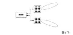
上述した実施形態では、各アレイアンテナ部に対して一つの無線部が設けられる場合について説明した。これによって、各アレイアンテナ部によって一つの指向性ビームを送信することができる。図17に示されるように、複数のアレイアンテナ部に対して一つの無線部を設けるようにしてもよい。これによって、無線部は複数のアレイアンテナ部へ高周波信号を出力し、複数のアレイアンテナ部は無線部によって供給された高周波信号を送信できる。 In the above-described embodiment, the case where one radio unit is provided for each array antenna unit has been described. Thus, one directional beam can be transmitted by each array antenna unit. As shown in FIG. 17, one radio unit may be provided for a plurality of array antenna units. Accordingly, the radio unit can output a high frequency signal to the plurality of array antenna units, and the plurality of array antenna units can transmit the high frequency signal supplied by the radio unit.
また、図18に示されるように、アレイアンテナ部に含まれる複数のアンテナ素子を複数の組に分割して、各組のアンテナ素子をアレイアンテナとして機能させるようにしてもよい。これによって、一つのアレイアンテナ部から複数の指向性ビームを送信できる。さらに、図18に示されるアレイアンテナ部を第2の実施形態に適用することによって、図19に示すように、単一のアレイアンテナ部から同時に複数の指向性ビームを送信する場合に、各指向性ビームを異なる端末装置へ向けるようにしてもよい。
また、上述した実施形態では、無線基地局装置と端末装置との間で通信について説明したが、送信装置と受信装置との間の通信についても適用できる。In addition, as shown in FIG. 18, a plurality of antenna elements included in the array antenna unit may be divided into a plurality of sets so that each set of antenna elements functions as an array antenna. Thereby, a plurality of directional beams can be transmitted from one array antenna unit. Furthermore, by applying the array antenna unit shown in FIG. 18 to the second embodiment, as shown in FIG. 19, when transmitting a plurality of directional beams simultaneously from a single array antenna unit, The beam may be directed to different terminal devices.
In the above-described embodiment, the communication between the radio base station apparatus and the terminal apparatus has been described. However, the present invention can also be applied to the communication between the transmission apparatus and the reception apparatus.
例えば、無線基地局装置600にアレイアンテナ部602、アレイアンテナ部604、及びアレイアンテナ部606が接続される。そして、アレイアンテナ部602によって送信される2本の指向性ビームはそれぞれ端末装置702、及び端末装置902へ向けられ、アレイアンテナ部604によって送信される2本の指向性ビームはそれぞれ端末装置702、及び端末装置802へ向けられ、アレイアンテナ部606によって送信される2本の指向性ビームはそれぞれ端末装置802、及び端末装置902へ向けられる。これによって、複数の端末装置へ異なる指向性ビームを放射することができるため、空間の利用効率を向上できる。 For example, the
上述した実施の形態において、アレイアンテナ部は指向性アンテナの一例であり、無線基地局装置は送信装置の一例であり、端末装置は受信装置の一例であり、指向性調整信号は指向性が異なる複数の指向性ビームの一例であり、指向性調整フィードバック信号は指向性ビームを表す情報の一例であり、アレイ通信能力情報は複数のアンテナの数と前記複数の指向性アンテナによって前記複数の指向性ビームを送信する方法を表す情報の一例である。また、アレイ通信能力信号は第1の信号の一例であり、指向性調整開始信号は第2の信号の一例であり、指向性調整フィードバック信号は第3の信号の一例であり、送信装置が備える指向性アンテナの数を表す情報と、前記指向性アンテナを識別する情報と、該指向性アンテナによって送信された指向性ビームの受信状況を表す情報を含む信号向性調整応答信号の一例である。 In the above-described embodiment, the array antenna unit is an example of a directional antenna, the radio base station apparatus is an example of a transmission apparatus, the terminal apparatus is an example of a reception apparatus, and the directivity adjustment signals have different directivities. It is an example of a plurality of directional beams, the directivity adjustment feedback signal is an example of information representing a directional beam, and the array communication capability information is the number of the plurality of antennas and the plurality of directional antennas. It is an example of the information showing the method of transmitting a beam. The array communication capability signal is an example of the first signal, the directivity adjustment start signal is an example of the second signal, and the directivity adjustment feedback signal is an example of the third signal, which is included in the transmission device. It is an example of a signal directivity adjustment response signal including information indicating the number of directional antennas, information for identifying the directional antennas, and information indicating the reception status of a directional beam transmitted by the directional antennas.
本発明は特定の実施例、変形例を参照しながら説明されてきたが、各実施例、変形例は単なる例示に過ぎず、当業者は様々な変形例、修正例、代替例、置換例等を理解するであろう。説明の便宜上、本発明の実施例に従った装置は機能的なブロック図を用いて説明されたが、そのような装置はハードウェアで、ソフトウェアでまたはそれらの組み合わせで実現されてもよい。本発明は上記実施例に限定されず、本発明の精神から逸脱することなく、様々な変形例、修正例、代替例、置換例等が包含される。 Although the present invention has been described with reference to specific embodiments and modifications, each embodiment and modification is merely an example, and those skilled in the art will recognize various modifications, modifications, alternatives, substitutions, and the like. Will understand. For convenience of explanation, an apparatus according to an embodiment of the present invention has been described using a functional block diagram, but such an apparatus may be implemented in hardware, software, or a combination thereof. The present invention is not limited to the above-described embodiments, and various variations, modifications, alternatives, substitutions, and the like are included without departing from the spirit of the present invention.
100…無線基地局装置
102、104…アレイアンテナ部
106、108…無線部
110…分波部
112…符号化・変調部
114…合成部
116…復調・復号部
118…メモリ部
120…中央制御部
122…アンテナ制御部
200…端末装置
202、204…アレイアンテナ部
206、208…無線部
210…分波部
212…符号化・変調部
214…合成部
216…復調・復号部
218…メモリ部
220…中央制御部
222…アンテナ制御部DESCRIPTION OF
Claims (13)
Translated fromJapanese前記送信装置は、前記受信装置へ、前記複数の指向性アンテナの各々から指向性が異なる複数の指向性ビームを順次送信し、前記複数の指向性ビームに対する応答信号に基づいて、前記受信装置へ送信する指向性ビームの指向性を設定し、
前記受信装置は、前記複数の指向性ビームを順次受信して、前記複数の指向性ビームの中から1又は複数の適切な指向性ビームを選択して、該指向性ビームを表す情報を前記送信装置へ通知する、無線通信システム。A wireless communication system including a transmission device including a plurality of directional antennas and a reception device that performs wireless communication with the transmission device,
The transmitting apparatus sequentially transmits a plurality of directional beams having different directivities from each of the plurality of directional antennas to the receiving apparatus, and based on response signals for the plurality of directional beams, to the receiving apparatus. Set the directivity of the directional beam to be transmitted,
The receiving apparatus sequentially receives the plurality of directional beams, selects one or more appropriate directional beams from the plurality of directional beams, and transmits information representing the directional beams. A wireless communication system for notifying a device.
前記受信装置は、前記第1の信号を順次受信して、前記第1の信号の受信状況を表す情報を含む第1の応答信号を前記送信装置へ通知する、請求項1に記載の無線通信システム。The transmission device receives a first signal including information indicating a method of transmitting the plurality of directional beams and the number of the plurality of directional antennas from each of the plurality of directional antennas to the reception device. Sequentially transmitting, and setting a transmission method of the plurality of directional beams based on a first response signal to the plurality of first signals,
The wireless communication according to claim 1, wherein the receiving device sequentially receives the first signal and notifies the transmitting device of a first response signal including information indicating a reception status of the first signal. system.
前記複数の指向性アンテナの各々から受信装置へ、複数の指向性ビームを順次送信する制御を行う制御部と、
前記複数の指向性ビームの各々を送信する際に、前記複数の指向性アンテナの各々について指向性の制御を行うアンテナ制御部と
を備え、
前記制御部は、前記複数の指向性ビームに対する応答信号に基づいて、前記アンテナ制御部へ、前記受信装置へ送信する指向性ビームの指向性を設定する、送信装置。A transmission device comprising a plurality of directional antennas,
A control unit that performs control to sequentially transmit a plurality of directional beams from each of the plurality of directional antennas to the receiving device;
An antenna control unit that controls directivity of each of the plurality of directional antennas when transmitting each of the plurality of directional beams;
The said control part is a transmitter which sets the directivity of the directional beam transmitted to the said receiver to the said antenna control part based on the response signal with respect to these directional beams.
前記送信装置によって前記複数の指向性アンテナの各々から送信される指向性が異なる複数の指向性ビームを順次受信する無線部と、
前記無線部によって受信された前記複数の指向性ビームの中から1又は複数の適切な指向性ビームを選択する制御部と
を備え、
前記無線部は、前記制御部によって選択された前記適切な指向性ビームを表す情報を前記送信装置へ送信する、受信装置。A receiving device that performs wireless communication with a transmitting device including a plurality of directional antennas,
A radio unit that sequentially receives a plurality of directional beams having different directivities transmitted from each of the plurality of directional antennas by the transmission device;
A controller that selects one or more appropriate directional beams from the plurality of directional beams received by the radio unit; and
The radio unit is a receiving device that transmits information representing the appropriate directional beam selected by the control unit to the transmitting device.
前記送信装置は、前記受信装置へ、前記複数の指向性アンテナの各々から指向性が異なる複数の指向性ビームを順次送信し、前記複数の指向性ビームに対する応答信号に基づいて、前記受信装置へ送信する指向性ビームの指向性を設定し、
前記受信装置は、前記複数の指向性ビームを順次受信して、前記複数の指向性ビームの中から1又は複数の適切な指向性ビームを選択して、該指向性ビームを表す情報を前記送信装置へ通知する、通信方法。A communication method executed by a transmission device including a plurality of directional antennas and a reception device that performs wireless communication with the transmission device,
The transmitting apparatus sequentially transmits a plurality of directional beams having different directivities from each of the plurality of directional antennas to the receiving apparatus, and based on response signals for the plurality of directional beams, to the receiving apparatus. Set the directivity of the directional beam to be transmitted,
The receiving apparatus sequentially receives the plurality of directional beams, selects one or more appropriate directional beams from the plurality of directional beams, and transmits information representing the directional beams. A communication method for notifying a device.
Priority Applications (5)
| Application Number | Priority Date | Filing Date | Title |
|---|---|---|---|
| JP2016031913AJP2017152830A (en) | 2016-02-23 | 2016-02-23 | Wireless communication system, transmission apparatus, reception apparatus, and communication method |
| EP16891649.2AEP3422596A4 (en) | 2016-02-23 | 2016-12-08 | WIRELESS COMMUNICATION SYSTEM, TRANSMISSION DEVICE, RECEIVING DEVICE, AND COMMUNICATION METHOD |
| CN201680082200.3ACN108702198A (en) | 2016-02-23 | 2016-12-08 | Wireless communication system, transmitting device, receiving device and communication method |
| PCT/JP2016/086546WO2017145493A1 (en) | 2016-02-23 | 2016-12-08 | Wireless communication system, transmitting device, receiving device, and communication method |
| US16/077,275US20190052345A1 (en) | 2016-02-23 | 2016-12-08 | Wireless communication system, transmitting device, receiving device, and communication method |
Applications Claiming Priority (1)
| Application Number | Priority Date | Filing Date | Title |
|---|---|---|---|
| JP2016031913AJP2017152830A (en) | 2016-02-23 | 2016-02-23 | Wireless communication system, transmission apparatus, reception apparatus, and communication method |
Publications (1)
| Publication Number | Publication Date |
|---|---|
| JP2017152830Atrue JP2017152830A (en) | 2017-08-31 |
Family
ID=59685052
Family Applications (1)
| Application Number | Title | Priority Date | Filing Date |
|---|---|---|---|
| JP2016031913APendingJP2017152830A (en) | 2016-02-23 | 2016-02-23 | Wireless communication system, transmission apparatus, reception apparatus, and communication method |
Country Status (5)
| Country | Link |
|---|---|
| US (1) | US20190052345A1 (en) |
| EP (1) | EP3422596A4 (en) |
| JP (1) | JP2017152830A (en) |
| CN (1) | CN108702198A (en) |
| WO (1) | WO2017145493A1 (en) |
Cited By (3)
| Publication number | Priority date | Publication date | Assignee | Title |
|---|---|---|---|---|
| JP2018201081A (en)* | 2017-05-25 | 2018-12-20 | 日本電信電話株式会社 | Wireless communication system, wireless communication method, and wireless communication apparatus |
| WO2021177575A1 (en)* | 2020-03-05 | 2021-09-10 | 엘지전자 주식회사 | Electronic device comprising antenna |
| US12438622B2 (en) | 2020-06-26 | 2025-10-07 | Samsung Electronics Co., Ltd. | Electronic device comprising plurality of antennas |
Families Citing this family (6)
| Publication number | Priority date | Publication date | Assignee | Title |
|---|---|---|---|---|
| JP7114236B2 (en)* | 2017-10-19 | 2022-08-08 | キヤノン株式会社 | Communication device, control method, and program |
| US10819448B2 (en)* | 2017-11-14 | 2020-10-27 | Qualcomm Incorporated | Detection and mitigation of antenna element failures |
| US10588089B1 (en)* | 2018-09-21 | 2020-03-10 | Qualcomm Incorporated | Mitigation of calibration errors |
| US11076303B2 (en)* | 2018-12-18 | 2021-07-27 | Sunsight Holdings, Llc | Antenna alignment tool generating earth browser file and related methods |
| CN115085773A (en) | 2021-03-10 | 2022-09-20 | 中兴通讯股份有限公司 | Antenna number changing method, device, equipment and storage medium |
| US12334998B2 (en)* | 2022-08-16 | 2025-06-17 | Qualcomm Incorporated | Capability for multiple beamforming codebooks |
Citations (2)
| Publication number | Priority date | Publication date | Assignee | Title |
|---|---|---|---|---|
| JP2004297750A (en)* | 2002-09-20 | 2004-10-21 | Mitsubishi Electric Corp | Wireless communication system |
| JP2008512955A (en)* | 2004-09-10 | 2008-04-24 | インターデイジタル テクノロジー コーポレーション | Measurement support for smart antennas in wireless communication systems |
Family Cites Families (12)
| Publication number | Priority date | Publication date | Assignee | Title |
|---|---|---|---|---|
| US7123924B2 (en)* | 2002-06-28 | 2006-10-17 | Interdigital Technology Corporation | Method and system for determining the speed and position of a mobile unit |
| US7453832B2 (en)* | 2003-02-12 | 2008-11-18 | Nortel Networks Limited | Transit link coordination systems and methods for a distributed wireless communication network |
| US20060068719A1 (en)* | 2004-09-28 | 2006-03-30 | Armond Hairapetian | System and method for optimizing a directional communication link |
| CN101091344B (en)* | 2004-12-28 | 2011-01-05 | 富士通株式会社 | Wireless communication system |
| US8731594B2 (en)* | 2006-09-12 | 2014-05-20 | Aruba Networks, Inc. | System and method for reliable multicast transmissions over shared wireless media for spectrum efficiency and battery power conservation |
| JP5278035B2 (en)* | 2009-02-25 | 2013-09-04 | ソニー株式会社 | COMMUNICATION DEVICE AND COMMUNICATION METHOD, COMPUTER PROGRAM, AND COMMUNICATION SYSTEM |
| JP2010206574A (en)* | 2009-03-04 | 2010-09-16 | Sony Corp | Communication device, communication method, computer program and communication system |
| JP2010206667A (en)* | 2009-03-05 | 2010-09-16 | Sony Corp | Communication device, communication method, computer program and communication system |
| US20110103495A1 (en)* | 2009-11-04 | 2011-05-05 | Itt Manufacturing Enterprises, Inc. | Communications link redundancy including multiple input, multiple output architecture |
| DE102014205283B4 (en)* | 2013-03-24 | 2019-03-28 | Avago Technologies International Sales Pte. Ltd. | Channel sharing in wireless communications |
| KR102309726B1 (en)* | 2014-07-10 | 2021-10-07 | 삼성전자 주식회사 | Communicating method in a wireless communication system using bean forminig and system thereof |
| JP6297177B2 (en)* | 2015-02-06 | 2018-03-20 | 三菱電機株式会社 | Antenna device |
- 2016
- 2016-02-23JPJP2016031913Apatent/JP2017152830A/enactivePending
- 2016-12-08CNCN201680082200.3Apatent/CN108702198A/enactivePending
- 2016-12-08USUS16/077,275patent/US20190052345A1/ennot_activeAbandoned
- 2016-12-08WOPCT/JP2016/086546patent/WO2017145493A1/ennot_activeCeased
- 2016-12-08EPEP16891649.2Apatent/EP3422596A4/ennot_activeWithdrawn
Patent Citations (2)
| Publication number | Priority date | Publication date | Assignee | Title |
|---|---|---|---|---|
| JP2004297750A (en)* | 2002-09-20 | 2004-10-21 | Mitsubishi Electric Corp | Wireless communication system |
| JP2008512955A (en)* | 2004-09-10 | 2008-04-24 | インターデイジタル テクノロジー コーポレーション | Measurement support for smart antennas in wireless communication systems |
Cited By (3)
| Publication number | Priority date | Publication date | Assignee | Title |
|---|---|---|---|---|
| JP2018201081A (en)* | 2017-05-25 | 2018-12-20 | 日本電信電話株式会社 | Wireless communication system, wireless communication method, and wireless communication apparatus |
| WO2021177575A1 (en)* | 2020-03-05 | 2021-09-10 | 엘지전자 주식회사 | Electronic device comprising antenna |
| US12438622B2 (en) | 2020-06-26 | 2025-10-07 | Samsung Electronics Co., Ltd. | Electronic device comprising plurality of antennas |
Also Published As
| Publication number | Publication date |
|---|---|
| EP3422596A1 (en) | 2019-01-02 |
| US20190052345A1 (en) | 2019-02-14 |
| EP3422596A4 (en) | 2019-09-18 |
| CN108702198A (en) | 2018-10-23 |
| WO2017145493A1 (en) | 2017-08-31 |
Similar Documents
| Publication | Publication Date | Title |
|---|---|---|
| WO2017145493A1 (en) | Wireless communication system, transmitting device, receiving device, and communication method | |
| US9246571B2 (en) | Method and apparatus of beam training for MIMO operation | |
| US9344165B2 (en) | Method and apparatus of beam training for MIMO operation and multiple antenna beamforming operation | |
| CN102132504B (en) | Method and site for beamforming by sector scanning | |
| CN102326338A (en) | Beamforming training for functionally constrained devices | |
| JP6861225B2 (en) | A method for testing radio frequency (RF) data packet signal transmitters and receivers for proper implied beamforming operation | |
| EP2398267B1 (en) | Communication apparatus, communication control method, and communication system | |
| JP6234634B2 (en) | Antenna device | |
| KR20160086291A (en) | System and method for selecting a beamforming configuration | |
| US10340994B2 (en) | Method for beam training in multiuser scenario and apparatus | |
| JP5804407B2 (en) | Wireless device | |
| CN106680601A (en) | Method for signal processing, active antenna and signal processing system | |
| JP2017092522A (en) | Communication device, communication method, and computer program | |
| CN113632385A (en) | Beamforming reception of downlink reference signals | |
| CN102783051B (en) | Communication equipment, communication control method and communication system | |
| CN106470063B (en) | Method and device for acquiring channel direction information | |
| JP2009159453A (en) | Wireless communication system, polarization plane adjustment method, base station, and sensor station | |
| EP3095203B1 (en) | Improved control of directive antennas for wireless links | |
| JP2012191281A (en) | Radio communication device | |
| WO2018150712A1 (en) | Wireless communication system and wireless communication method | |
| CN118575092A (en) | Radar-based Radio Frequency (RF) sensing | |
| JP7096452B2 (en) | Wireless communication system and wireless communication method | |
| JP4778982B2 (en) | Reception apparatus and interference suppression method | |
| KR100438804B1 (en) | Indoor communication system & method using multiple adaptive phased array antenna | |
| US10945308B2 (en) | Radio system for radio communication |
Legal Events
| Date | Code | Title | Description |
|---|---|---|---|
| A521 | Request for written amendment filed | Free format text:JAPANESE INTERMEDIATE CODE: A821 Effective date:20160224 | |
| A621 | Written request for application examination | Free format text:JAPANESE INTERMEDIATE CODE: A621 Effective date:20180713 | |
| A521 | Request for written amendment filed | Free format text:JAPANESE INTERMEDIATE CODE: A821 Effective date:20180717 | |
| A131 | Notification of reasons for refusal | Free format text:JAPANESE INTERMEDIATE CODE: A131 Effective date:20190604 | |
| A02 | Decision of refusal | Free format text:JAPANESE INTERMEDIATE CODE: A02 Effective date:20191203 |