JP2017150732A - Heat exchanger - Google Patents
Heat exchangerDownload PDFInfo
- Publication number
- JP2017150732A JP2017150732AJP2016033304AJP2016033304AJP2017150732AJP 2017150732 AJP2017150732 AJP 2017150732AJP 2016033304 AJP2016033304 AJP 2016033304AJP 2016033304 AJP2016033304 AJP 2016033304AJP 2017150732 AJP2017150732 AJP 2017150732A
- Authority
- JP
- Japan
- Prior art keywords
- unit
- flow path
- lattice structure
- heat transfer
- unit cell
- Prior art date
- Legal status (The legal status is an assumption and is not a legal conclusion. Google has not performed a legal analysis and makes no representation as to the accuracy of the status listed.)
- Pending
Links
Images


Landscapes
- Heat-Exchange Devices With Radiators And Conduit Assemblies (AREA)
Abstract
Translated fromJapaneseDescription
Translated fromJapaneseこの発明は、熱交換器に関し、特に、流路部内に2次伝熱部が設けられた熱交換器に関する。 The present invention relates to a heat exchanger, and more particularly to a heat exchanger in which a secondary heat transfer section is provided in a flow path section.
従来、流路部内に2次伝熱部が設けられた熱交換器が知られている(たとえば、特許文献1参照)。 Conventionally, a heat exchanger in which a secondary heat transfer section is provided in a flow path section is known (see, for example, Patent Document 1).
このような熱交換器としては、たとえば、1次伝熱部としてのプレートに仕切られた流路内に、2次伝熱部としてのコルゲートフィンが配置されたコアを備えたプレートフィン型熱交換器などがある。上記特許文献1では、ベースの上面に材料を積層する積層造形法により、コアの構成要素を造形する技術が開示されている。積層造形法を用いることにより、板材の加工成形などにより形成される板状フィンとは異なる立体構造の2次伝熱部を形成することが可能となる。上記特許文献1には、コアの構成要素として、立体的な格子状の構造を繰り返し配列した立体格子構造を造形することが開示されている。 As such a heat exchanger, for example, a plate fin type heat exchange provided with a core in which corrugated fins as secondary heat transfer units are arranged in a flow path partitioned by plates as primary heat transfer units There are containers. In the said
しかしながら、上記特許文献1では、立体的な格子状の構造を繰り返し配列した立体格子構造をコアの構成要素として造形することが開示されているのみであり、具体的にどのような立体格子構造の2次伝熱部を形成するかについては明確な開示がない。2次伝熱部に立体的な格子状構造を採用した場合、単位重量当たりの表面積(比表面積)を増大させることができるので、熱交換性能の向上が期待できる。そこで、効果的に熱交換器の性能向上を図ることが可能な立体格子構造の2次伝熱部が望まれている。 However, the
この発明は、上記のような課題を解決するためになされたものであり、この発明の1つの目的は、効果的に熱交換器の性能向上を図ることが可能な立体格子構造の2次伝熱部を有する熱交換器を提供することである。 The present invention has been made to solve the above-described problems, and one object of the present invention is to provide a secondary transmission having a three-dimensional lattice structure capable of effectively improving the performance of a heat exchanger. It is to provide a heat exchanger having a heat section.
上記目的を達成するために、この発明による熱交換器は、1次伝熱部を介して仕切られた複数の流路部を含み、複数の流路部のそれぞれを通過する流体間で熱交換を行うコアを備え、少なくとも1つの流路部は、流路部内に配置され、立体的な格子状の構造を有する単位立体格子構造が繰り返し複数配列されて構成された2次伝熱部を含み、単位立体格子構造は、単位立体格子構造の各々の頂点から延びて単位立体格子構造の中心近傍で互いに接続された複数の第1梁部を含む。 In order to achieve the above object, a heat exchanger according to the present invention includes a plurality of flow passage portions partitioned through a primary heat transfer portion, and exchanges heat between fluids passing through each of the plurality of flow passage portions. And at least one flow path section includes a secondary heat transfer section that is arranged in the flow path section and is configured by repeatedly arranging a plurality of unit three-dimensional lattice structures having a three-dimensional lattice structure. The unit three-dimensional lattice structure includes a plurality of first beam portions extending from the vertices of the unit three-dimensional lattice structure and connected to each other in the vicinity of the center of the unit three-dimensional lattice structure.
なお、本発明における「単位立体格子構造の頂点」とは、角の端部および第1梁部の端部を含む概念である。本発明における「単位立体格子構造の中心」とは、単位立体格子構造の各頂点を頂点とする立体的な多面体空間の内部であり、単位立体格子構造の各頂点から略等距離にある点である。多面体空間が立方体や直方体の場合、たとえば対角線の交点である。多面体空間が五角柱の場合、たとえば上面および底面の各重心点を結ぶ直線の中点としてよい。多面体空間の重心としてもよい。 In the present invention, “the apex of the unit solid lattice structure” is a concept including an end portion of the corner and an end portion of the first beam portion. The “center of the unit three-dimensional lattice structure” in the present invention is the inside of a three-dimensional polyhedral space having each vertex of the unit three-dimensional lattice structure as an apex, and is at a substantially equal distance from each vertex of the unit three-dimensional lattice structure. is there. When the polyhedral space is a cube or a rectangular parallelepiped, for example, it is an intersection of diagonal lines. When the polyhedral space is a pentagonal prism, for example, it may be the midpoint of a straight line connecting the center of gravity points of the top and bottom surfaces. It may be the center of gravity of the polyhedral space.
この発明による熱交換器では、上記のように、立体的な格子状の構造を有する単位立体格子構造が繰り返し複数配列されて構成された2次伝熱部を設け、単位立体格子構造に、単位立体格子構造の各々の頂点から延びて単位立体格子構造の中心近傍で互いに接続された複数の第1梁部を設ける。これにより、複数の第1梁部によって単位立体格子構造の表面積(伝熱面積)を容易に大きくすることができる。また、単位立体格子構造を通過する流体の流れを遮るように複数の第1梁部が単位立体格子構造の中心近傍に集まるので、効率的に乱流を生じさせて熱伝達を効率的に行うことができる。これらの結果、熱伝達性能に優れた2次伝熱部を構成することができる。また、単位立体格子構造の各々の頂点と中心近傍とが複数の第1梁部により接続されるので、どの方向の外力に対しても機械的強度(剛性)を確保しやすい構造とすることができる。そのため、熱伝達性能のみならず、2次伝熱部の機械的強度(剛性)を容易に確保することができる。以上により、本発明によれば、効果的に熱交換器の性能向上を図ることが可能な立体格子構造の2次伝熱部を構成することができる。その結果、熱交換器の性能向上を図ることができる。 In the heat exchanger according to the present invention, as described above, there is provided a secondary heat transfer section configured by repeatedly arranging a plurality of unit three-dimensional lattice structures having a three-dimensional lattice-like structure. A plurality of first beam portions extending from each vertex of the three-dimensional lattice structure and connected to each other in the vicinity of the center of the unit three-dimensional lattice structure are provided. Thereby, the surface area (heat transfer area) of the unit solid lattice structure can be easily increased by the plurality of first beam portions. Further, since the plurality of first beam portions gather near the center of the unit three-dimensional lattice structure so as to block the flow of fluid passing through the unit three-dimensional lattice structure, the turbulent flow is efficiently generated and the heat transfer is efficiently performed. be able to. As a result, a secondary heat transfer section having excellent heat transfer performance can be configured. Moreover, since each vertex of the unit three-dimensional lattice structure and the vicinity of the center are connected by the plurality of first beam portions, a structure in which mechanical strength (rigidity) can be easily secured against an external force in any direction can be obtained. it can. Therefore, not only the heat transfer performance but also the mechanical strength (rigidity) of the secondary heat transfer section can be easily ensured. As described above, according to the present invention, a secondary heat transfer section having a three-dimensional lattice structure capable of effectively improving the performance of the heat exchanger can be configured. As a result, the performance of the heat exchanger can be improved.
上記発明による熱交換器において、好ましくは、単位立体格子構造は、多角形状の底面から立ち上がる角柱状の立体形状を有しており、底面と直交する辺を構成する複数の第2梁部をさらに含む。このように構成すれば、角柱状の立体形状を有する単位立体格子構造の角部に相当する位置に第2梁部が配置されるので、単位立体格子構造の機械的強度を効果的に向上させることができる。その結果、単位立体格子構造の機械的強度を確保しつつ比表面積(重量辺りの表面積)を大きくすることができる。 In the heat exchanger according to the present invention, preferably, the unit solid lattice structure has a prismatic solid shape rising from a polygonal bottom surface, and further includes a plurality of second beam portions constituting sides orthogonal to the bottom surface. Including. If comprised in this way, since a 2nd beam part is arrange | positioned in the position corresponded to the corner | angular part of the unit solid lattice structure which has a prismatic solid shape, the mechanical strength of a unit solid lattice structure is improved effectively. be able to. As a result, the specific surface area (surface area per weight) can be increased while ensuring the mechanical strength of the unit solid lattice structure.
この場合、好ましくは、単位立体格子構造は、直方体状の立体形状を有しており、底面と直交する各辺を構成する4本の第2梁部と、第2梁部の両端部から延びて単位立体格子構造の中心で互いに接続される8本の第1梁部と、を含む。このように構成すれば、直方体状の単位立体格子構造の四隅に配置された4本の第2梁部の両端が、それぞれ第1梁部を介して単位立体格子構造の中心で連結される構造になるので、熱伝達性能を向上させつつさらに容易に機械的強度を確保することができる。 In this case, preferably, the unit solid lattice structure has a rectangular parallelepiped solid shape, and extends from the four second beam portions constituting each side orthogonal to the bottom surface and both ends of the second beam portion. And eight first beam portions connected to each other at the center of the unit solid lattice structure. If comprised in this way, the structure where the both ends of the four 2nd beam parts arrange | positioned at the four corners of a rectangular parallelepiped unit solid lattice structure are respectively connected by the center of a unit solid lattice structure through the 1st beam part. Therefore, the mechanical strength can be more easily ensured while improving the heat transfer performance.
上記単位立体格子構造が直方体状の立体形状を有する構成において、好ましくは、第2梁部は、単位立体格子構造が有する直方体状の立体形状を構成する辺の内、最大の長さを有する辺方向である長手方向に沿って延びている。このように構成すれば、第2梁部を単位立体格子構造の長手方向(直方体の最大長さの辺に沿う方向)に延びる柱として形成することができるので、単位立体格子構造の長手方向の機械的強度を容易に確保することができる。また、積層造形法により2次伝熱部(単位立体格子構造の配列)を造形する場合に、支柱となる第2梁部を起点に第1梁部を形成することができるので、形状精度が良く安定した造形が可能となる。 In the configuration in which the unit solid lattice structure has a rectangular solid shape, preferably, the second beam portion is the side having the maximum length among the sides constituting the rectangular solid shape that the unit solid lattice structure has. It extends along the longitudinal direction which is the direction. If comprised in this way, since a 2nd beam part can be formed as a pillar extended in the longitudinal direction (direction along the side of the maximum length of a rectangular parallelepiped) of a unit solid lattice structure, it can be formed in the longitudinal direction of a unit solid lattice structure. Mechanical strength can be easily secured. In addition, when forming a secondary heat transfer section (arrangement of unit three-dimensional lattice structure) by the additive manufacturing method, the first beam section can be formed starting from the second beam section serving as a support, so that the shape accuracy is high. Good and stable modeling is possible.
上記単位立体格子構造が直方体状の立体形状を有する構成において、好ましくは、1次伝熱部と2次伝熱部とは、一体形成されており、第2梁部は、流路部の内壁としての1次伝熱部の表面と略平行に延びている。このように構成すれば、1次伝熱部および2次伝熱部を積層造形法によりまとめて形成する場合に、流路部の隔壁となる1次伝熱部と、2次伝熱部(単位立体格子構造)の柱としての第2梁部とを、造形方向に沿って積層形成して行くことができる。その結果、積層造形法では単純に積層していく構造が最も形状精度を確保しやすいため、1次伝熱部および第2梁部の形状精度を容易に確保することができる。柱となる第2梁部の形状精度が確保されることにより、第2梁部を起点として第1梁部も精度良く安定して形成することが可能となるので、1次伝熱部および2次伝熱部の形状精度を容易に確保できる。 In the configuration in which the unit solid lattice structure has a rectangular parallelepiped solid shape, preferably, the primary heat transfer portion and the secondary heat transfer portion are integrally formed, and the second beam portion is the inner wall of the flow path portion. And extending substantially parallel to the surface of the primary heat transfer section. If comprised in this way, when forming a primary heat-transfer part and a secondary heat-transfer part collectively by an additive manufacturing method, the primary heat-transfer part used as the partition of a flow-path part, and a secondary heat-transfer part ( The second beam portion as a column of the (unit solid lattice structure) can be laminated and formed along the forming direction. As a result, in the additive manufacturing method, the structure of simply laminating is the easiest to ensure the shape accuracy, so the shape accuracy of the primary heat transfer portion and the second beam portion can be easily ensured. By ensuring the shape accuracy of the second beam portion as the column, the first beam portion can be formed with high accuracy and stability starting from the second beam portion. The shape accuracy of the next heat transfer section can be easily secured.
上記単位立体格子構造が直方体状の立体形状を有する構成において、好ましくは、単位立体格子構造は、流路部を通過する流体の進行方向である流路奥行き方向に沿って隙間なく配列されており、単位立体格子構造の流路奥行き方向の第1長さは、流路奥行き方向におけるコアの流路部長さを第1長さで除算して割りきれる大きさである。このように構成すれば、流路部を通過する流体の進行方向(流路奥行き方向)に沿って単位立体格子構造を配列した場合に、流路部の流路奥行き方向の両端部(入口部分および出口部分)で完全な形状の単位立体格子構造が形成される。これにより、2次伝熱部の入口または出口の強度を確保することができる。 In the configuration in which the unit three-dimensional lattice structure has a rectangular parallelepiped shape, preferably, the unit three-dimensional lattice structure is arranged without gaps along the flow path depth direction, which is the traveling direction of the fluid passing through the flow path section. The first length in the flow path depth direction of the unit three-dimensional lattice structure is a size that can be divided by dividing the flow path length of the core in the flow path depth direction by the first length. According to this configuration, when the unit three-dimensional lattice structure is arranged along the traveling direction of the fluid passing through the flow path portion (flow path depth direction), both end portions (inlet portions) of the flow path portion in the flow path depth direction And a unit solid lattice structure of a complete shape is formed at the exit portion). Thereby, the intensity | strength of the entrance or exit of a secondary heat-transfer part is securable.
上記発明による熱交換器において、好ましくは、単位立体格子構造は、流路部の流路奥行き方向と直交する流路幅方向に沿って隙間なく配列されており、単位立体格子構造の流路幅方向の第2長さは、流路部の幅を第2長さで除算して余りが出る大きさである。ここで、流路部の幅を第2長さで除算して余りが出ない場合には、2次伝熱部の流路幅方向両端の単位立体格子構造の側面が流路部の内壁と一体化してしまい、完全な格子構造にならなくなる。これに対して、余りが出る場合には、完全な形状の単位立体格子構造が流路部の内側に確実に収まるので、単位立体格子構造による比表面積の増加や乱流形成の効果を、2次伝熱部の流路幅方向の両端位置でも確実に得ることができる。なお、流路部の内壁と2次伝熱部との間に不必要な隙間を形成する必要はないので、除算した余りは、小さいほど好ましい。 In the heat exchanger according to the above invention, preferably, the unit three-dimensional grid structure is arranged without a gap along a channel width direction orthogonal to the channel depth direction of the channel unit, and the channel width of the unit three-dimensional grid structure The second length in the direction is such that the remainder is obtained by dividing the width of the flow path portion by the second length. Here, when there is no remainder when the width of the flow path part is divided by the second length, the side surfaces of the unit three-dimensional lattice structure at both ends of the secondary heat transfer part in the flow path width direction are the inner wall of the flow path part. They will be integrated and will not have a perfect lattice structure. On the other hand, when the remainder is generated, the unit solid lattice structure having a perfect shape is surely accommodated inside the flow path portion, so that the effect of increasing the specific surface area and turbulent flow due to the unit solid lattice structure is 2 It can be reliably obtained at both end positions in the flow path width direction of the next heat transfer section. In addition, since it is not necessary to form an unnecessary gap between the inner wall of the flow path part and the secondary heat transfer part, the remainder after division is preferably as small as possible.
上記発明による熱交換器において、好ましくは、第1梁部は、単位立体格子構造の底面に対して30度以上90度未満の角度で傾斜している。ここで、積層造形法により2次伝熱部(単位立体格子構造の配列)を造形する場合、材料を造形方向に積層していくので、造形される構造が造形方向(積層方向)と直交する水平方向に近付くほど、重力によって造形性(形状精度)が悪くなる。そこで、第1梁部は、単位立体格子構造の底面に対して30度以上90度未満の角度で傾斜させることにより、単位立体格子構造(第1梁部)を形状精度が良好な状態で造形することができる。 In the heat exchanger according to the present invention, preferably, the first beam portion is inclined at an angle of 30 degrees or more and less than 90 degrees with respect to the bottom surface of the unit solid lattice structure. Here, when a secondary heat transfer section (array of unit three-dimensional lattice structure) is modeled by the layered modeling method, since the materials are stacked in the modeling direction, the modeled structure is orthogonal to the modeling direction (stacking direction). The closer to the horizontal direction, the worse the formability (shape accuracy) due to gravity. Therefore, the first beam portion is inclined at an angle of 30 degrees or more and less than 90 degrees with respect to the bottom surface of the unit three-dimensional lattice structure, so that the unit three-dimensional lattice structure (first beam portion) is shaped with good shape accuracy. can do.
本発明によれば、上記のように、効果的に熱交換器の性能向上を図ることが可能な立体格子構造の2次伝熱部を有する熱交換器を提供することができる。 ADVANTAGE OF THE INVENTION According to this invention, the heat exchanger which has the secondary heat-transfer part of the three-dimensional lattice structure which can aim at the performance improvement of a heat exchanger effectively as mentioned above can be provided.
以下、本発明の実施形態を図面に基づいて説明する。 Hereinafter, embodiments of the present invention will be described with reference to the drawings.
まず、図1〜図7を参照して、本実施形態による熱交換器100の構成について説明する。本実施形態では、プレートフィン型の熱交換器の例について説明する。プレートフィン型の熱交換器は、複数の流路部を平板状の1次伝熱部(プレート)により仕切り、流路部内に2次伝熱部(フィン)を配置した構造を有する。 First, with reference to FIGS. 1-7, the structure of the
(熱交換器の全体構成)
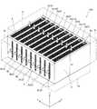
図1に示すように、熱交換器100は、所定の方向に積み重なるように並ぶ複数の流路部2を含むコア1を備えている。コア1は、複数の流路部2の間に設けられた1次伝熱部3(図2参照)を含む。複数の流路部2は1次伝熱部3を介して互いに仕切られている。(Overall configuration of heat exchanger)
As shown in FIG. 1, the
具体的には、複数の流路部2は、第1流体が流れる複数の第1流路部2aと、第2流体が流れる複数の第2流路部2bとを含む。コア1は、複数の流路部2のそれぞれを通過する流体間で熱交換を行う。すなわち、コア1は、第1流路部2aを流れる第1流体と第2流路部2bを流れる第2流体との間で、熱交換を行うように構成されている。 Specifically, the plurality of
コア1は、略直方体形状を有する。以下、各流路部2の配列方向をX方向とし、X方向に対して直交する面内で、互いに直交する2方向をY方向およびZ方向とする。 The
(コア)
複数の第1流路部2aと複数の第2流路部2bとは、1次伝熱部3を介してX方向に交互に並ぶ(積層される)ようにコア1に形成されている。積層方向(X方向)におけるコア1の両端には、それぞれ側面部4が設けられている。また、Z方向におけるコア1の両端は、それぞれ側面部5が設けられている。本実施形態では、コア1は、たとえば積層造形法などの立体造形技術により、全体が一体形成されている。コア1は、熱伝導性の高い金属材料により形成されている。(core)
The plurality of first
第1流路部2aと第2流路部2bとは、1次伝熱部3に挟まれた略矩形断面の流路形状を有する。図1の構成例では、第1流路部2aは、コア1をY方向に貫通するように構成された流体通路であり、第2流路部2bは、コア1をZ方向に貫通するように構成された流体通路である。したがって、第1流体は、第1流路部2aの一方側の開口6a(図6参照)から他方側の開口6aに向けてY方向に流通する。第2流体は、第2流路部2bの一方側の開口6b(図3参照)から他方側の開口6bに向けてZ方向に流通する。コア1は、熱交換する第1流体と第2流体との流通方向が互いに直交する、いわゆる直交流方式の熱交換器コアとして構成されている。 The first
それぞれの第1流路部2aには、一方側の開口6aと他方側の開口6aとを覆うヘッダ7aが接続され、各ヘッダ7aにより第1流路部2aへの第1流体の供給および回収が行われる。同様に、それぞれの第2流路部2bには、一方側の開口6bと他方側の開口6bとを覆うヘッダ7bが接続され、各ヘッダ7bにより第2流路部2bへの第2流体の供給および回収が行われる。 Each first
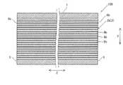
図2に示すように、1次伝熱部3は、第1流路部2aと第2流路部2bとを仕切る隔壁として構成されている。1次伝熱部3は、第1流路部2aと第2流路部2bとの間で、Y方向およびZ方向に延びる平板形状を有する部分である。1次伝熱部3において、第1流路部2aと第2流路部2bとの内部にそれぞれ露出する表面3aが、熱交換の1次伝熱面として機能する。 As shown in FIG. 2, the primary
それぞれの流路部2には、内部に2次伝熱部8aまたは8bが設けられている。第1流路部2aの内部には、2次伝熱部8aが設けられている。第2流路部2bの内部には、2次伝熱部8bが設けられている。本実施形態では、1次伝熱部3と、2次伝熱部8aおよび8bとは、一体形成されている。 Each
第1流路部2aの2次伝熱部8aは、第1流路部2a内に配置され、立体的な格子状の構造(立体格子構造)を有する単位格子10(図4および図5参照)が繰り返し複数配列されて構成されている。単位格子10は、特許請求の範囲の「単位立体格子構造」の一例である。2次伝熱部8aにおいて、それぞれの単位格子10の表面が、熱交換の2次伝熱面として機能する。2次伝熱部8aは、複数の単位格子10をX方向、Y方向およびZ方向に隙間なく配列した構造を有する。単位格子10の詳細な構造については、後述する。 The secondary
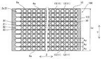
第2流路部2bは、第1流路部2aよりも幅狭(X方向の幅)の流路として形成されている。図3に示すように、第2流路部2bの2次伝熱部8bは、第2流路部2b内で板状に形成されている。すなわち、図2および図3に示した構成例では、2次伝熱部8bは、立体的な格子状の構造(立体格子構造)ではなく、板状フィンにより構成されている。2次伝熱部8bは、第2流路部2b内でX方向の一端(一方の1次伝熱部3)から他端(他方の1次伝熱部3)に渡って平板状に形成されている。また、2次伝熱部8bは、第2流路部2b内でY方向の一端から他端までの間に略等間隔で複数配列されている。各2次伝熱部8bは、第2流路部2b内でZ方向の一端から他端まで直線状に延びている。そのため、第2流路部2bは、内部が複数の2次伝熱部8bによって区画されており、Z方向に延びる流路がY方向に並べて配置された構造となっている。 The second
(単位格子)
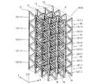
以下、第1流路部2aの2次伝熱部8aに設けられた単位格子10について説明する。図4には、単位格子10の一例を示し、図5では単位格子10を配列した配列構造の一例を示している。単位格子10の説明のため、直交座標系の各軸方向X、YおよびZを設定する。(Unit lattice)
Hereinafter, the
図4に示す単位格子10は、複数の梁部11の組み合わせにより格子形状に形成されている。単位格子10は、梁(柱)のみにより構成されている必要はなく、部分的に壁状の面構造が存在してもよい。ただし、単位重量当たりの表面積(比表面積)の観点からは、壁状の面構造は少ない方が比表面積を大きくすることができる。また、梁(柱)は、直線状形状に限られず、曲線状形状を有していてもよい。単位格子10は、積層造形法などの立体造形技術により造形することができる。 The
単位格子10は、単位立体空間U内に、複数の梁部11を格子状に配置したものとして定義することが可能である。単位立体空間Uは、単位格子10に外接する最小の空間としてよい。単位立体空間Uとしてどのような立体空間を想定することも可能であるが、造形する際に隙間なく配列するためには制限が生じる。また、立体造形技術により造形する場合の造形のし易さ(造形性)も考慮すれば、単位立体空間Uは、多面体空間であり、角柱形状(四角柱、六角柱など)などのいくつかのものが好ましい。以下、便宜的にこのような単位立体空間Uを用いて説明を行う。 The
図4の構成例では、単位格子10は、多角形状の底面Bから立ち上がる角柱状の立体形状を有している。つまり、単位格子10は、底面Bを有する多角柱形状の単位立体空間Uに内接する形状を有する。より具体的には、単位格子10は、長方形状(または正方形状)の底面Bから垂直に立ち上がる直方体状の立体形状を有する。すなわち、図4の単位格子10は、X、YおよびZの各軸方向の辺を有する直方体形状の単位立体空間Uにおいて、複数の梁部11を配置した構造を有する。図5の配列は、単位格子10が配置された単位立体空間Uを上下左右に隙間なく配列していったものと考えることができる。 In the configuration example of FIG. 4, the
図4に示すように、本実施形態では、単位格子10は、単位格子10の各々の頂点13から延びて単位格子10の中心近傍で互いに接続された複数の第1梁部12を含む。言い換えると、第1梁部12は、単位格子10の中心近傍から単位格子10の角部(頂点13)に向けて延びるように形成されている。 As shown in FIG. 4, in the present embodiment, the
単位格子10の頂点13は、梁部11の外側端部であり、単位立体空間Uの頂点のいずれかに位置する。図4では全ての梁部11の外側端部が幾何学的な頂点(2本の辺が交わる角部)を構成しているが、1本の梁部11の端部のみであっても、頂点13であるとする。単位格子10の中心近傍とは、単位立体空間Uの内部であり、単位格子10の各頂点13から略等距離にある点である。図4のように単位立体空間Uが直方体であれば、中心は、対角線の交点または単位立体空間Uの重心位置である。 The
第1梁部12は、単位格子10の頂点13と中心近傍の接続部14との間を直線状に延びるように形成されている。本実施形態では、第1梁部12は、単位格子10の8つの頂点13の各々から、合計8本設けられている。本実施形態では、第1梁部12は、単位格子10の底面Bに対して30度以上90度未満の角度θで傾斜するように形成されている。図4の構成例では、第1梁部12の底面Bに対する傾斜角度θは、約36.4度である。なお、直方体状の単位立体空間Uでは、各頂点から単位立体空間Uの中心に向けて延びる直線は、頂点同士を結ぶ対角線となる。そのため、図4に示した直方体状の単位格子10では、接続部14を挟んで対向する一対の第1梁部12が単位格子10の対角線を構成するように直線状に連続して延びている。つまり、単位格子10では、接続部14を挟んで対向する4対の第1梁部12がそれぞれ4本の対角線を構成するように形成されている。 The
図4の構成例では、単位格子10は、底面Bと直交する辺を構成する複数の第2梁部15をさらに含む。つまり、第2梁部15は、底面Bから垂直に立ち上がるようにZ軸に沿って延びている。なお、第2梁部15は、図2に示したように、第2梁部15は、第1流路部2aの内壁としての1次伝熱部3の表面3aと略平行に延びている。 In the configuration example of FIG. 4, the
第2梁部15は単位格子10に4本設けられている。それぞれの第2梁部15は、底面Bの4つの角部(頂点13)に配置され、四角柱(直方体)外形の単位格子10のZ方向の各辺を構成している。したがって、各第2梁部15は、両端部においてそれぞれ第1梁部12の端部と接続されている。言い換えると、8本の第1梁部12が、それぞれ対応する第2梁部15の端部15aから延びて単位格子10の中心近傍(接続部14)で互いに接続されている。 Four
これにより、第1実施形態では、端部同士で互いに接続された2本の第1梁部12と1本の第2梁部15とにより、三角枠状の梁構造が形成されている。この三角枠状の梁構造が4組設けられ、単位格子10の中心近傍の接続部14で互いに接続されている。 Accordingly, in the first embodiment, a triangular frame-shaped beam structure is formed by the two
本実施形態では、図5に示したように、それぞれの単位格子10は、X、YおよびZの各軸方向に沿って隙間なく配列されている。すなわち、単位格子10は、第1流路部2aを通過する流体の進行方向である流路奥行き方向(Y方向)に沿って隙間なく配列されている。また、単位格子10は、流路奥行き方向(Y方向)と直交する第1流路部2aの流路幅方向(X方向)に沿って隙間なく配列されている。なお、図5では、互いに隣接する単位格子10の間の第2梁部15は、明確な境界線によって別個に形成されているように図示しているが、実際に一体形成すれば、個々の第2梁部15は区別なく一体になる。また、単位格子10は、第1流路部2aの高さ方向(Z方向)に沿って隙間なく配列されている。したがって、Z方向に隣接する単位格子10同士の第1梁部12は、端部同士が互いに接続されている。それぞれの単位格子10は一体形成されているので、単位格子10の配列全体では、2次伝熱部8aのZ方向の一端から他端まで延びる第2梁部15が、X方向およびY方向に配列されているということができる。 In the present embodiment, as shown in FIG. 5, the
図4に示すように、個々の単位格子10としては、X軸方向、Y軸方向およびZ軸方向の各々に、長さAx、AyおよびAzを有する。第1流路部2aの構造との関係では、第1流路部2aを通過する流体の進行方向がY方向であるので、長さAyが、第1流路部2aの流路奥行き方向における単位格子10の長さに相当する。また、後述する造形方向(Z方向)との対応のため、Z方向を第1流路部2aの高さ方向とし、残るX方向を第1流路部2aの流路幅方向とする。したがって、長さAzが単位格子10の高さであり、第2梁部15の長さL2に等しい。長さAxが単位格子10の幅である。長さAyおよび長さAxは、それぞれ、特許請求の範囲の「第1長さ」および「第2長さ」の一例である。 As shown in FIG. 4, each
本実施形態では、単位格子10は、長さAx、AyおよびAzのうちで、長さAzが最大となるように構成されている(Ax、Ay<Az)。したがって、Z方向が単位格子10の長手方向であり、第2梁部15は、単位格子10が有する直方体状の立体形状を構成する辺の内、最大の長さを有する辺方向である長手方向に沿って延びている。第2梁部15の長さL2は、第1梁部12の長さL1よりも大きい。なお、単位格子10の長手方向は、単位格子10自体の形状に基づいて定義される方向であり、第1流路部2aおよび2次伝熱部8aの向き(X、Y、Z方向)とは無関係に定義できる。一方、流路奥行き方向および流路幅方向は、第1流路部2a(コア1)の構造(方向)に基づいて定義される方向である。したがって、「流路奥行き方向(または流路幅方向)における単位格子10の長さ」とは、第1流路部2aの向きを基準として決定される単位格子10の相対的な寸法であり、たとえば同じ単位格子10でも、流路奥行き方向がY方向の場合とX方向の場合とでは、異なる値となる。「単位格子10の長手方向における単位格子10の長さ」と言う場合は、第1流路部2aの構造とは無関係に、単位格子10自体の形状により決定される寸法を意味する。 In the present embodiment, the
本実施形態では、単位格子10の流路奥行き方向(Y方向)の長さAyは、流路奥行き方向における第1流路部2aの長さLy(図6参照)を長さAyで除算して割りきれる大きさである。すなわち、Ay=Ly/N(Nは自然数)である。なお、図6に示すように、2次伝熱部8aは、第1流路部2aのY方向の一端から他端までの全範囲にわたって形成されており、2次伝熱部8aのY方向の長さLyは、第1流路部2aのY方向の長さに等しい。各単位格子10は、第1流路部2aの流路奥行き方向(Y方向)に沿って隙間なく配列されているため、長さAyが2次伝熱部8a(第1流路部2a)の長さLyのN分の1となることにより、2次伝熱部8a(第1流路部2a)のY方向端部の単位格子10が完全な形状で形成されている。つまり、2次伝熱部8a(第1流路部2a)の入口面および出口面に単位格子10の第2梁部15がそれぞれ配置される。 In the present embodiment, the length Ay of the
また、本実施形態では、単位格子10の流路幅方向の長さAxは、第1流路部2aの幅Lx(図2参照)を長さAxで除算して余りが出る大きさである。すなわち、Ax=(Lx+P)/M(Mは自然数、Pは剰余)である。上記のように、各単位格子10は、第1流路部2aの流路幅方向(X方向)に沿って隙間なく配列されているため、第1流路部2aに単位格子10をM個配列すると幅Lx内に収まらなくなる。そのため、単位格子10は、第1流路部2aの幅Lx内に収まるように、X方向に(M−1)個配列される。その結果、図2に示したように、単位格子10の端面を構成する第2梁部15が第1流路部2aの内壁(1次伝熱部3の表面3a)に一体化せずに内壁から離間して形成される。この構成は、2次伝熱部8aのX方向の幅が、第1流路部2aのX方向の幅Lxよりも小さい、と言い換えてもよい。図2の構成例では、1次伝熱部3の表面3aと最外部の第2梁部15との間に、間隔CLが設けられており、表面3aと第2梁部15とが離間している。 In the present embodiment, the length Ax of the
このように、単位格子10の各軸方向の大きさは、第1流路部2aの大きさ(2次伝熱部8aの大きさ)に応じて設定される。なお、個々の梁部11(第1梁部12および第2梁部15)の断面形状(梁部の延びる方向と直交する断面形状)は、特に限定されない。本実施形態では、図4に示した各梁部11の断面形状は共通であり、1辺が長さAtの正方形状である。断面形状は、正方形以外の矩形、六角形や八角形などの多角形、円又は楕円形状などでもよい。梁部11の断面積(太さ)は、造形技術上の制約や、単位格子10または2次伝熱部8a全体としての機械的強度の制約などを考慮した上で、小さいほど比表面積を大きくできる点で好ましい。たとえば、長さAtは、梁部11(第1梁部12または第2梁部15)の長さの1/5未満であり、1/10未満から1/20以上程度であってよい。 Thus, the size of each
ところで、積層造形法による立体構造の造形は、水平なベース面から上方に向けて、水平断面構造を積層させていくことにより行われる。重力の作用があるため、積層造形法は完全に任意の形状を造形できるわけではない。たとえば、下側が支持されない水平面または水平に近い傾斜した構造は、造形中に崩れたり、造形時に歪んで形状精度が悪化したりする。反対に、造形方向に一致して延びる垂直な梁(柱)は、重力下での積層により精度よく造形することが可能である。 By the way, modeling of the three-dimensional structure by the layered modeling method is performed by laminating the horizontal cross-sectional structure from the horizontal base surface upward. Because of the action of gravity, the additive manufacturing method cannot completely form an arbitrary shape. For example, a horizontal plane that is not supported on the lower side or an inclined structure that is close to horizontal may collapse during modeling, or may be distorted during modeling and shape accuracy may deteriorate. On the contrary, a vertical beam (column) extending in conformity with the modeling direction can be accurately modeled by stacking under gravity.
そこで、本実施形態のコア1では、図2のZ方向の一方(下側)の端面(XY平面)をベース面に一致させ、Z方向を造形方向に一致させた状態で造形される。すなわち、図2の下側から上側に向けて造形することになる。この場合、Z方向に延びる1次伝熱部3(および第2流路部2bの2次伝熱部8b)と、単位格子10の第2梁部15とが、造形方向(Z方向)に一致した状態で積層造形されることになり、精度よく造形される。 Therefore, the
この場合、図4に示した単位格子10の底面Bはベース面と略平行になる。第1梁部12は、単位格子10の底面B(ベース面)に対して30度以上90度未満の角度θで傾斜するように形成されているため、水平面に対して十分な傾斜角度が確保される。その結果、Z方向を造形方向に一致させた状態で造形することにより、第1梁部12も精度よく造形することが可能となる。 In this case, the bottom surface B of the
一方、図2のZ方向の他方(上側)に位置する第1流路部2aの端部は、造形方向の上側を覆う構造となってしまう。そこで、図7に示すように、第1流路部2aは、第2梁部15の端部が接続される内壁面30を備え、内壁面30が単位格子10の底面B(ベース面)に対して30度以上90度未満の角度φで傾斜するように形成されている。 On the other hand, the edge part of the 1st flow-
内壁面30は、たとえば、図7に示す構成例のように、第1流路部2aの内部側に向けて突出するように形成される。内壁面30は、角度φの傾斜面32を有する凸部31を含んで形成される。図7の構成例では、凸部31は、四角錐形状に形成されている。単位格子10の第2梁部15は、四角錐形状の内壁面30の頂点部分に接続されている。凸部31は、内壁面30に複数配列され、それぞれの凸部31の頂点部分が、柱部33を介して、対応するそれぞれの第2梁部15と接続される。図7では、便宜的に、Y方向端部側の柱部33のみを図示している。 The
(本実施形態の効果)
本実施形態では、以下のような効果を得ることができる。(Effect of this embodiment)
In the present embodiment, the following effects can be obtained.
本実施形態では、上記のように、立体的な格子状の構造を有する単位格子10が繰り返し複数配列されて構成された2次伝熱部8aを設け、単位格子10に、単位格子10の各々の頂点13から延びて単位格子10の中心近傍で互いに接続された複数の第1梁部12を設ける。これにより、複数の第1梁部12によって単位格子10の表面積(伝熱面積)を容易に大きくすることができる。また、単位格子10を通過する流体の流れを遮るように複数の第1梁部12が単位格子10の中心近傍に集まるので、効率的に乱流を生じさせて熱伝達を効率的に行うことができる。これらの結果、熱伝達性能に優れた2次伝熱部8aを構成することができる。また、単位格子10の各々の頂点13と中心近傍とが複数の第1梁部12により接続されるので、どの方向の外力に対しても機械的強度(剛性)を確保しやすい構造とすることができる。そのため、熱伝達性能のみならず、2次伝熱部8aの機械的強度(剛性)を容易に確保することができる。以上により、本実施形態の熱交換器100によれば、効果的に熱交換器の性能向上を図ることが可能な立体格子構造の2次伝熱部8aを構成することができる。その結果、熱交換器の性能向上を図ることができる。 In the present embodiment, as described above, the secondary
また、本実施形態では、上記のように、単位格子10に、角柱状の単位格子10の底面Bと直交する辺を構成する複数の第2梁部15を設ける。これにより、角柱状の単位格子10の角部(底面Bにおける角部)に相当する位置に第2梁部15が配置されるので、単位格子10の機械的強度を効果的に向上させることができる。その結果、単位格子10の機械的強度を確保しつつ比表面積(重量辺りの表面積)を大きくすることができる。 Further, in the present embodiment, as described above, the
また、本実施形態では、上記のように、単位格子10を直方体状の立体形状に構成し、底面Bと直交する各辺を構成する4本の第2梁部15と、第2梁部15の両端部から延びて単位格子10の中心で互いに接続される8本の第1梁部12とを、単位格子10に設ける。これにより、直方体状の単位格子10の四隅に配置された4本の第2梁部15の両端が、それぞれ第1梁部12を介して単位格子10の中心で連結される構造になるので、熱伝達性能を向上させつつさらに容易に機械的強度を確保することができる。 Further, in the present embodiment, as described above, the
また、本実施形態では、上記のように、第2梁部15を、単位格子10が有する直方体状の立体形状を構成する辺の内、最大の長さを有する辺方向である長手方向(Z方向)に沿って延びるように形成する。これにより、第2梁部15を単位格子10の長手方向(Z方向)に延びる柱として形成することができるので、単位格子10の長手方向(Z方向)の機械的強度を容易に確保することができる。また、積層造形法により2次伝熱部8a(単位格子10の配列)を造形する場合に、支柱となる第2梁部15を起点に第1梁部12を形成することができるので、形状精度が良く安定した造形が可能となる。 Further, in the present embodiment, as described above, the
また、本実施形態では、上記のように、1次伝熱部3と2次伝熱部8aとを一体形成し、第2梁部15を、第1流路部2aの内壁としての1次伝熱部3の表面3aと略平行に延びるように形成する。これにより、1次伝熱部3および2次伝熱部8aを積層造形法によりまとめて形成する場合に、第1流路部2aの隔壁となる1次伝熱部3と、2次伝熱部8a(単位格子10)の柱としての第2梁部15とを、造形方向(Z方向)に沿って積層形成して行くことができる。その結果、1次伝熱部3および第2梁部15の形状精度を容易に確保することができる。柱となる第2梁部15の形状精度が確保されることにより、第2梁部15を起点として第1梁部12も精度良く安定して形成することが可能となるので、1次伝熱部3および2次伝熱部8aの形状精度を容易に確保できる。 In the present embodiment, as described above, the primary
また、本実施形態では、上記のように、単位格子10を第1流路部2aの流路奥行き方向(Y方向)に沿って隙間なく配列し、単位格子10の流路奥行き方向(Y方向)の長さAyを、流路奥行き方向(Y方向)における2次伝熱部8aの長さLyを長さAyで除算して割りきれる大きさとする。これにより、2次伝熱部8aの流路奥行き方向(Y方向)の両端部(入口部分および出口部分)で完全な形状の単位格子10を形成することができるので、2次伝熱部8aの入口または出口の強度を確保することができる。また、両端部に単位格子10の頂点位置の第1梁部12同士の交点を配置することが可能となり、全ての第1梁部12を途切れることなく造形することが可能となる。 Further, in the present embodiment, as described above, the
また、本実施形態では、上記のように、単位格子10を第1流路部2aの流路幅方向(X方向)に沿って隙間なく配列し、単位格子10の流路幅方向(X方向)の長さAxを、第1流路部2aの幅Lxを長さAxで除算して余りが出る大きさとする。これにより、完全な形状の単位格子10が第1流路部2aの内側に(表面3aから間隔CLだけ離間した状態で)確実に収めることができる。その結果、単位格子10による比表面積の増加や乱流形成の効果を、2次伝熱部8aの流路幅方向(X方向)の両端位置でも確実に得ることができる。 In the present embodiment, as described above, the unit lattices 10 are arranged without gaps along the flow passage width direction (X direction) of the first
また、本実施形態では、上記のように、第1梁部12を、単位格子10の底面Bに対して30度以上90度未満の角度θで傾斜するように形成する。これにより、重力によって造形性(形状精度)が悪くなることを抑制することができるので、単位格子10(第1梁部12)を形状精度が良好な状態で造形することができる。 In the present embodiment, as described above, the
(比較実験結果の説明)
本実施形態の効果を確認するために行った比較実験結果について説明する。本実施形態による熱交換器100と、従来型のプレートフィン型熱交換器(比較例)とで、熱交換特性についての対比を行った。(Explanation of comparative experiment results)
A description will be given of the results of a comparative experiment conducted to confirm the effect of the present embodiment. The
比較例の熱交換器は、所定長さのコルゲートフィンが半ピッチずつずれるように配置されたセレート型のフィンを2次伝熱部に備える構成とした。 The heat exchanger of the comparative example has a configuration in which a secondary heat transfer section includes serrated fins arranged so that corrugated fins of a predetermined length are shifted by half a pitch.
本実施形態による熱交換器100は、2次伝熱部8aの表面積を比較例の熱交換器の2次伝熱部(セレート型フィン)の表面積と略一致するように設計したものである。 The
その結果、2次伝熱部8aは、比較例の2次伝熱部(セレート型フィン)と比較して12%軽量化され、比表面積が増大した。また、本実施形態による熱交換器100および比較例による熱交換器の熱交換特性として、コルバーンのj因子を求めた。本実施形態による熱交換器100では、比較例の熱交換器(セレート型フィン)と比較して、j因子が約2倍の値を示した。この結果から、本実施形態の熱交換器100による比表面積の増加と、これに伴う熱交換特性の向上の効果が得られることが確認された。 As a result, the secondary
(変形例)
なお、今回開示された実施形態は、すべての点で例示であって制限的なものではないと考えられるべきである。本発明の範囲は、上記した実施形態の説明ではなく特許請求の範囲によって示され、さらに特許請求の範囲と均等の意味および範囲内でのすべての変更(変形例)が含まれる。(Modification)
The embodiment disclosed this time should be considered as illustrative in all points and not restrictive. The scope of the present invention is shown not by the above description of the embodiment but by the scope of claims for patent, and further includes all modifications (modifications) within the meaning and scope equivalent to the scope of claims for patent.
たとえば、上記実施形態では単位格子10に第1梁部12および第2梁部15の2種類の梁部11を設けた例を示したが、本発明はこれに限られない。たとえば図8に示す第1変形例のように、第1梁部12のみにより構成された単位格子110を設けてもよい。単位格子110は、特許請求の範囲の「単位立体格子構造」の一例である。単位格子110では、単位格子110の8つの頂点13の各々から延びて、単位格子110の中心近傍の接続部14で互いに接続された複数(8本)の第1梁部12が設けられている。この単位格子110に、第2梁部15をZ方向の各辺に設ければ、図4に示した単位格子10と同様になる。このほか、たとえば単位立体空間Uの四角形状の側面Sの対角線を構成する第3梁部111を、単位格子110に加えてもよい。 For example, in the above-described embodiment, the example in which the two types of
単位格子を構成する梁部11は、全てが頂点13を通らなくてもよい。たとえば接続部14の位置を通過するようにZ方向に延びる梁部を設けてもよい。ただし、頂点13に端部が配置されるように梁部11を構成することにより、隣接した他の単位格子を構成する梁部11と容易に相互接続して機械的強度を効果的に向上させることが可能である。 All of the
また、上記実施形態では、四角柱(直方体)形状の単位格子10(単位立体空間U)の例を示したが、本発明はこれに限られない。本発明では、四角柱(直方体)形状の単位格子(単位立体空間U)であってもよい。たとえば、図9に示したように、六角柱形状の単位格子120(単位立体空間U)を設けてもよい。単位格子120は、特許請求の範囲の「単位立体格子構造」の一例である。単位格子120では、六角柱形状の単位格子120の12個の頂点13の各々から延びて、単位格子120の中心近傍の接続部14で互いに接続された複数の第1梁部12が設けられている。このほか、単位格子(単位立体空間U)は、4角柱および六角柱以外の他の多角柱形状であってもよいし、たとえば四角錐形状や三角錐形状など、角柱形状以外でもよい。 Moreover, in the said embodiment, although the example of the unit cell 10 (unit solid space U) of a quadratic prism (cuboid) shape was shown, this invention is not limited to this. In the present invention, a unit cell (unit space U) having a quadrangular prism (cuboid) shape may be used. For example, as shown in FIG. 9, a hexagonal prism-shaped unit lattice 120 (unit solid space U) may be provided. The
また、上記実施形態では、プレートフィン型の熱交換器の例を示したが、本発明はこれに限られない。本発明では、たとえば図10に示すシェルアンドチューブ型の熱交換器200に本発明を適用してもよい。熱交換器200は、円筒状のシェル(胴部)210内に多数のチューブ220を配置した構造を有する。シェル210内には、複数のバッフル211が配置され、バッフル211によりチューブ220が保持されるとともに、バッフル211とシェル210との間の隙間またはバッフル211の開口部を介して流路部212が構成されている。シェル210内でチューブ220の周囲を流れる第1流体と、チューブ220内を流れる第2流体との間で熱交換が行われる。チューブ220は、特許請求の範囲の「1次伝熱部」の一例である。ここで、たとえば図10のバッフル211間の流路部分(ハッチング部分)に、単位格子10が繰り返し複数配列されて構成された2次伝熱部213が設けられる。なお、単位格子の図示は省略する。また、たとえば、チューブ220の内部に単位格子10を配列して2次伝熱部を構成してもよい。本発明では、1次伝熱部により仕切られた流路部の内部に2次伝熱部が配置される構造の熱交換器であれば、どのようなタイプの熱交換器であってもよい。 Moreover, in the said embodiment, although the example of the plate fin type heat exchanger was shown, this invention is not limited to this. In the present invention, for example, the present invention may be applied to a shell and tube
また、上記実施形態では、積層造形法などの立体造形技術により、コア1の全体を一体形成した例を示したが、本発明はこれに限られない。本発明では、単位格子10が繰り返し複数配列された2次伝熱部8aの部分だけを立体造形技術により形成してもよい。そして、その他の構造部分は構造材の積み重ねにより構成し、予め造形しておいた2次伝熱部8aとともに、ろう付けなどによりまとめて接合してもよい。 Moreover, in the said embodiment, although the example which integrally formed the
また、上記実施形態では、第1流路部2aと第2流路部2bとのうち、第1流路部2aのみに単位格子10が繰り返し複数配列された2次伝熱部8aを形成した例を示したが、本発明はこれに限られない。本発明では、第1流路部2aおよび第2流路部2bの両方に、単位格子10が繰り返し複数配列された2次伝熱部を形成してもよい。 Moreover, in the said embodiment, the secondary heat-
また、上記実施形態では、第1流路部2aと第2流路部2bとを設けて2種類の流体間で熱交換を行う例を示したが、本発明はこれに限られない。本発明では、3種類以上の流体間で熱交換を行うように、3種類以上の流路部を設けてもよい。 Moreover, in the said embodiment, although the 1st flow-
また、上記実施形態では、第1流体と第2流体とが互いに直交する向きに流れる直交流型の熱交換器の例を示したが、本発明はこれに限られない。本発明では、第1流体と第2流体とが同じ向きに流れる並行流型や、第1流体と第2流体とが反対方向に流れる対向流型の熱交換器であってもよい。 Moreover, in the said embodiment, although the example of the crossflow type heat exchanger with which a 1st fluid and a 2nd fluid flow in the direction orthogonal to each other was shown, this invention is not limited to this. In the present invention, a parallel flow type in which the first fluid and the second fluid flow in the same direction, or a counter flow type heat exchanger in which the first fluid and the second fluid flow in opposite directions may be used.
また、上記実施形態では、第2梁部15を、第1流路部2aの内壁としての1次伝熱部3の表面3aと略平行に延びるように形成する例を示したが、本発明はこれに限られない。たとえば、第2梁部が1次伝熱部3の表面3aと直交する向きに延びるようにしてもよい。 Moreover, although the
また、上記実施形態では、第2梁部15を、単位格子10の長手方向(Z方向)に沿って延びるように形成する例を示したが、本発明はこれに限られない。本発明では、第2梁部が単位格子の短手方向に沿って延びるように形成してもよい。つまり、長さAxまたは長さAyが長さAzよりも大きくなってもよい。 Moreover, although the example which forms the
また、上記実施形態では、第1流路部2aを通過する流体の進行方向である流路奥行き方向(Y方向)における単位格子10の長さAyを、Y方向における第1流路部2aの長さLyを長さAyで除算して割りきれる大きさとする例を示したが、本発明はこれに限られない。本発明では、第1流路部2aの長さLyを長さAyで除算して割り切れない大きさとなるように、長さAyを設定してもよい。 Moreover, in the said embodiment, length Ay of the
なお、上記実施形態では、第1流路部2aがY方向に直線状に形成されている例を示したが、第1流路部2aが屈曲していてもよい。その場合、流路奥行き方向における第1流路部2aの長さは、第1流路部2aを通過する流体が流れる経路長と考えてよい。 In the above embodiment, the example in which the first
また、上記実施形態では、単位格子10のX方向の長さAxを、第1流路部2aの幅Lxを長さAxで除算して余りが出る大きさとする例を示したが、本発明はこれに限られない。本発明では、第1流路部2aの幅Lxを長さAxで除算して割り切れる大きさとなるように、長さAxを設定してもよい。 In the above embodiment, the example has been shown in which the length Ax in the X direction of the
また、上記実施形態では、第1梁部12を、単位格子10の底面Bに対して30度以上90度未満の角度θで傾斜するように形成する例を示したが、本発明はこれに限られない。本発明では、第1梁部12を30度未満の角度で傾斜させてもよい。この場合、Z方向に造形するのが難しい場合には、造形方向に対してZ方向を傾斜させた向きで2次伝熱部8aを造形してもよい。 Moreover, in the said embodiment, although the example which forms the
1 コア
2、212 流路部
2a 第1流路部
2b 第2流路部
3 1次伝熱部
3a 表面
8a、213 2次伝熱部
10、110、120 単位格子(単位立体格子構造)
12 第1梁部
15 第2梁部
220 チューブ(1次伝熱部)
Ay 長さ(第1長さ)
Ax 長さ(第2長さ)
B 底面
X方向(流路幅方向)
Y方向(流路奥行き方向)
Z方向(長手方向)
θ 角度DESCRIPTION OF
12
Ay length (first length)
Ax length (second length)
B Bottom X direction (channel width direction)
Y direction (flow path depth direction)
Z direction (longitudinal direction)
θ angle
Claims (8)
Translated fromJapanese少なくとも1つの前記流路部は、前記流路部内に配置され、立体的な格子状の構造を有する単位立体格子構造が繰り返し複数配列されて構成された2次伝熱部を含み、
前記単位立体格子構造は、前記単位立体格子構造の各々の頂点から延びて前記単位立体格子構造の中心近傍で互いに接続された複数の第1梁部を含む、熱交換器。Including a plurality of flow path sections partitioned via a primary heat transfer section, comprising a core for exchanging heat between fluids passing through each of the plurality of flow path sections,
At least one of the flow passage portions includes a secondary heat transfer portion that is arranged in the flow passage portion and is configured by repeatedly arranging a plurality of unit solid lattice structures having a three-dimensional lattice structure.
The unit three-dimensional lattice structure includes a plurality of first beam portions extending from the vertices of the unit three-dimensional lattice structure and connected to each other in the vicinity of the center of the unit three-dimensional lattice structure.
直方体状の立体形状を有しており、
前記底面と直交する各辺を構成する4本の前記第2梁部と、
前記第2梁部の両端部から延びて前記単位立体格子構造の中心で互いに接続される8本の前記第1梁部と、を含む、請求項2に記載の熱交換器。The unit three-dimensional lattice structure is
It has a rectangular solid shape.
The four second beam portions constituting each side orthogonal to the bottom surface;
The heat exchanger according to claim 2, further comprising eight first beam portions extending from both ends of the second beam portion and connected to each other at the center of the unit solid lattice structure.
前記第2梁部は、前記流路部の内壁としての前記1次伝熱部の表面と略平行に延びている、請求項3または4のいずれか1項に記載の熱交換器。The primary heat transfer section and the secondary heat transfer section are integrally formed,
5. The heat exchanger according to claim 3, wherein the second beam portion extends substantially parallel to a surface of the primary heat transfer portion as an inner wall of the flow path portion.
前記単位立体格子構造の前記流路奥行き方向の第1長さは、前記流路奥行き方向における前記コアの流路部長さを前記第1長さで除算して割りきれる大きさである、請求項3〜5のいずれか1項に記載の熱交換器。The unit three-dimensional lattice structure is arranged without a gap along the flow path depth direction, which is the traveling direction of the fluid passing through the flow path section,
The first length in the channel depth direction of the unit three-dimensional lattice structure is a size that can be divided by dividing the channel length of the core in the channel depth direction by the first length. The heat exchanger according to any one of 3 to 5.
前記単位立体格子構造の前記流路幅方向の第2長さは、前記流路部の幅を前記第2長さで除算して余りが出る大きさである、請求項3〜6のいずれか1項に記載の熱交換器。The unit three-dimensional lattice structure is arranged without a gap along the flow channel width direction orthogonal to the flow channel depth direction of the flow channel part,
The second length in the channel width direction of the unit three-dimensional lattice structure is a size in which a remainder is obtained by dividing the width of the channel portion by the second length. The heat exchanger according to item 1.
Priority Applications (1)
| Application Number | Priority Date | Filing Date | Title |
|---|---|---|---|
| JP2016033304AJP2017150732A (en) | 2016-02-24 | 2016-02-24 | Heat exchanger |
Applications Claiming Priority (1)
| Application Number | Priority Date | Filing Date | Title |
|---|---|---|---|
| JP2016033304AJP2017150732A (en) | 2016-02-24 | 2016-02-24 | Heat exchanger |
Publications (1)
| Publication Number | Publication Date |
|---|---|
| JP2017150732Atrue JP2017150732A (en) | 2017-08-31 |
Family
ID=59740530
Family Applications (1)
| Application Number | Title | Priority Date | Filing Date |
|---|---|---|---|
| JP2016033304APendingJP2017150732A (en) | 2016-02-24 | 2016-02-24 | Heat exchanger |
Country Status (1)
| Country | Link |
|---|---|
| JP (1) | JP2017150732A (en) |
Cited By (1)
| Publication number | Priority date | Publication date | Assignee | Title |
|---|---|---|---|---|
| KR20220102307A (en)* | 2021-01-13 | 2022-07-20 | (주)오토젠 | Mold device and mold manufacturing method to produce the same |
Citations (6)
| Publication number | Priority date | Publication date | Assignee | Title |
|---|---|---|---|---|
| JPS5541336A (en)* | 1978-09-14 | 1980-03-24 | Toyo Radiator Kk | Core for use in laminated plate type heat exchanger and method of manufacturing the same |
| JP2002540556A (en)* | 1999-03-22 | 2002-11-26 | インターナショナル フュエル セルズ,エルエルシー | Compact selective oxidizer for fuel cell power installations |
| US20040140085A1 (en)* | 1999-10-08 | 2004-07-22 | Dobbs Gregory M. | Plate-type heat exchanger |
| JP2004225696A (en)* | 2003-01-21 | 2004-08-12 | General Electric Co <Ge> | Method and apparatus for exchanging heat |
| US20060245987A1 (en)* | 2005-05-02 | 2006-11-02 | United Technologies Corporation | Micro heat exchanger with thermally conductive porous network |
| US8453717B1 (en)* | 2009-07-20 | 2013-06-04 | Hrl Laboratories, Llc | Micro-architected materials for heat sink applications |
- 2016
- 2016-02-24JPJP2016033304Apatent/JP2017150732A/enactivePending
Patent Citations (6)
| Publication number | Priority date | Publication date | Assignee | Title |
|---|---|---|---|---|
| JPS5541336A (en)* | 1978-09-14 | 1980-03-24 | Toyo Radiator Kk | Core for use in laminated plate type heat exchanger and method of manufacturing the same |
| JP2002540556A (en)* | 1999-03-22 | 2002-11-26 | インターナショナル フュエル セルズ,エルエルシー | Compact selective oxidizer for fuel cell power installations |
| US20040140085A1 (en)* | 1999-10-08 | 2004-07-22 | Dobbs Gregory M. | Plate-type heat exchanger |
| JP2004225696A (en)* | 2003-01-21 | 2004-08-12 | General Electric Co <Ge> | Method and apparatus for exchanging heat |
| US20060245987A1 (en)* | 2005-05-02 | 2006-11-02 | United Technologies Corporation | Micro heat exchanger with thermally conductive porous network |
| US8453717B1 (en)* | 2009-07-20 | 2013-06-04 | Hrl Laboratories, Llc | Micro-architected materials for heat sink applications |
Cited By (2)
| Publication number | Priority date | Publication date | Assignee | Title |
|---|---|---|---|---|
| KR20220102307A (en)* | 2021-01-13 | 2022-07-20 | (주)오토젠 | Mold device and mold manufacturing method to produce the same |
| KR102452583B1 (en)* | 2021-01-13 | 2022-10-12 | (주)오토젠 | Mold device and mold manufacturing method to produce the same |
Similar Documents
| Publication | Publication Date | Title |
|---|---|---|
| EP3193123B1 (en) | Heat exchangers | |
| JP2018521293A (en) | Fin assembly for heat exchanger and heat exchanger having fin assembly | |
| EP2426453B1 (en) | Total heat exchange element | |
| KR101655889B1 (en) | Heat exchange reactor and method for producing the same | |
| US20120037349A1 (en) | Heat exchange element | |
| JP2006525485A (en) | Heat exchanger core | |
| JP6578964B2 (en) | Laminate heat exchanger | |
| US20190033016A1 (en) | Heat Exchanger | |
| EP4023997B1 (en) | Heat exchange plate and heat exchanger containing same | |
| JP2017150732A (en) | Heat exchanger | |
| CN106482556B (en) | Box-shaped laminated heat exchanger with fins between corner holes and heat exchange device | |
| CN115003979A (en) | Plate Heat Exchanger | |
| JP6923324B2 (en) | Laminated objects and heat exchangers | |
| US12117250B2 (en) | Heat exchanger with variable cross sectional flow path areas | |
| JP6422585B2 (en) | Plate heat exchanger | |
| JP6983789B2 (en) | Sandwich-like structural element with an open core structure consisting of tightly packed tetrahedra | |
| KR101072686B1 (en) | Three-dimensional truss type periodic cellular materials having internal walls and manufacture method of the same | |
| CN119654535B (en) | Indoor heat exchanger and air conditioner | |
| JP6244172B2 (en) | Reactor fuel assembly grid | |
| JP2021050838A5 (en) | ||
| KR102857695B1 (en) | Thermal management structure to improve battery heat dissipation efficiency | |
| JP5328961B2 (en) | Heat exchanger | |
| JP2009162427A (en) | Heat exchanger | |
| JP2022151995A (en) | plate heat exchanger | |
| JP2016003775A (en) | Stacked heat exchanger |
Legal Events
| Date | Code | Title | Description |
|---|---|---|---|
| A621 | Written request for application examination | Free format text:JAPANESE INTERMEDIATE CODE: A621 Effective date:20190124 | |
| A977 | Report on retrieval | Free format text:JAPANESE INTERMEDIATE CODE: A971007 Effective date:20191127 | |
| A131 | Notification of reasons for refusal | Free format text:JAPANESE INTERMEDIATE CODE: A131 Effective date:20191203 | |
| A601 | Written request for extension of time | Free format text:JAPANESE INTERMEDIATE CODE: A601 Effective date:20200128 | |
| A02 | Decision of refusal | Free format text:JAPANESE INTERMEDIATE CODE: A02 Effective date:20200630 |