JP2017149246A - Vehicular door opening/closing device - Google Patents
Vehicular door opening/closing deviceDownload PDFInfo
- Publication number
- JP2017149246A JP2017149246AJP2016032988AJP2016032988AJP2017149246AJP 2017149246 AJP2017149246 AJP 2017149246AJP 2016032988 AJP2016032988 AJP 2016032988AJP 2016032988 AJP2016032988 AJP 2016032988AJP 2017149246 AJP2017149246 AJP 2017149246A
- Authority
- JP
- Japan
- Prior art keywords
- door
- vehicle
- damping force
- user
- sensor
- Prior art date
- Legal status (The legal status is an assumption and is not a legal conclusion. Google has not performed a legal analysis and makes no representation as to the accuracy of the status listed.)
- Granted
Links
Images


Landscapes
- Power-Operated Mechanisms For Wings (AREA)
Abstract
Translated fromJapaneseDescription
Translated fromJapanese本発明は、車両用ドア開閉装置に関する。 The present invention relates to a vehicle door opening and closing device.
車両用ドア開閉装置において、チェックリンク及びチェック機構部の構成に応じて、ドア開閉時のモータ駆動負荷の増減パターンを変更するようにした技術が知られている。こうすることにより、車両ごとに異なるリンク部材を使用した場合でも、制御回路において、この増減パターンに応じたモータ電圧の指令値の補正処理を行うことにより対応できるので、様々なリンク部材を使用することができ、汎用性が高いドア開閉装置として使用することができるようになっている(下記、特許文献1参照)。 In a vehicle door opening / closing device, a technique is known in which an increase / decrease pattern of a motor driving load at the time of opening / closing a door is changed according to the configuration of a check link and a check mechanism. In this way, even when a different link member is used for each vehicle, the control circuit can cope with this by performing correction processing of the command value of the motor voltage according to the increase / decrease pattern, so various link members are used. It can be used as a highly versatile door opening and closing device (see Patent Document 1 below).
上記特許文献1に記載の技術によると、チェックリンク及びチェック機構部の構成に応じて、ドア開閉時のモータ駆動負荷の増減パターンを変更することができるが、ドアを閉閉するときの安全性を考慮した技術ではない。 According to the technique described in Patent Document 1, the increase / decrease pattern of the motor drive load at the time of opening and closing the door can be changed according to the configuration of the check link and the check mechanism, but safety when closing and closing the door It is not a technology that takes into account.
例えば、ユーザが車両用のドアを閉じるときに、ユーザーや別のユーザの身体の一部、例えば、強風などにより手や指をドアと車体との間に挟む危険もあり得るため、このような危険に対する安全性を確保することが求められている。 For example, when the user closes the door for the vehicle, there is a risk that a part of the body of the user or another user, for example, a hand or a finger may be caught between the door and the vehicle body due to a strong wind or the like. It is required to ensure safety against danger.
ここで、安全性を確保するために、常にドアを閉じにくく設定することも考えられる。しかしながら、このように設定すると、ドア開閉時の安全性が確保される一方でドアがスムーズに開閉できなくなるためユーザの利便性が損なわれる。 Here, in order to ensure safety, it is conceivable to always set the door so as not to close. However, with this setting, safety at the time of opening and closing the door is ensured, while the door cannot be opened and closed smoothly, and thus convenience for the user is impaired.
本発明は、上記事情に鑑みてなされたものであり、車両用ドアが閉められるときにユーザを車両用ドアと車体との間に挟むことを防止する技術を適切なタイミングで作動させ、安全性及び利便性を確保することができる車両用ドア開閉装置を提供することを目的とする。 The present invention has been made in view of the above circumstances, and operates a technique for preventing a user from being pinched between the vehicle door and the vehicle body when the vehicle door is closed at an appropriate timing. It is another object of the present invention to provide a vehicle door opening and closing device that can ensure convenience.
本発明の車両用ドア開閉装置は、車両の幅方向に開閉されるドアを制御する車両用ドア開閉装置であって、前記ドアの開閉時の減衰力を調整する調整手段と、前記ドアの開閉状態を検出するドア開閉検出手段と、前記ドア開閉検出手段により前記ドアの開状態を検出しているときに、前記ドアと前記車両との間のユーザの存在を検出するユーザ検出手段と、前記ユーザ検出手段により前記ユーザの存在を検出した場合、その検出状態から所定時間以内か否かを判断し、所定時間以内である場合に前記調整手段を調整して前記減衰力を変化させる制御手段と、を備えることを特徴とする。 A vehicle door opening and closing device according to the present invention is a vehicle door opening and closing device that controls a door that is opened and closed in the width direction of the vehicle, the adjusting means for adjusting a damping force when the door is opened and closed, and the opening and closing of the door Door opening / closing detection means for detecting a state, user detecting means for detecting the presence of a user between the door and the vehicle when the door opening / closing detection means is detecting an open state of the door, and Control means for determining whether or not the presence of the user is detected by a user detection means and determining whether or not it is within a predetermined time from the detection state, and adjusting the adjustment means and changing the damping force if it is within the predetermined time; It is characterized by providing.
このように構成することにより、車両用ドア開閉装置は、車両用ドアが閉められるときにユーザを車両用ドアと車体との間に挟むことを防止する技術を適切なタイミングで作動させ、安全性及び利便性を確保することができる。 With this configuration, the vehicular door opening / closing device operates the technology for preventing the user from being pinched between the vehicular door and the vehicle body when the vehicular door is closed, so that safety is ensured. And convenience can be ensured.
また、前記制御手段は、前記検出状態からの経過時間に応じて前記調整手段の前記減衰力を変化させるようにしても良い。 Further, the control means may change the damping force of the adjustment means in accordance with an elapsed time from the detection state.
このように構成すると、車両用ドア開閉装置はドア開閉の減衰力を時間に応じて調整することが可能になる。 If comprised in this way, it will become possible for the vehicle door opening / closing apparatus to adjust the damping force of door opening / closing according to time.
また、前記ユーザ検出手段は、前記車両に前記ドアを収納したときに、前記ドアの縁部を収納する収納部にユーザが接触しているか否かを検出するセンサとしても良い。 The user detection means may be a sensor that detects whether or not a user is in contact with a storage portion that stores an edge of the door when the door is stored in the vehicle.
これにより、例えば、車両のドアを収納する収納部にユーザの手や指が接触している場合に、当該手や指を検出することができ、当該手や指を検出していた状態から所定時間だけドアを閉めるときの減衰力を強くできるため、ドアが閉められるときに手や指を挟むような事態を防止することができ、安全性を向上させることができる。ユーザが子供の場合はドアの表側からは子供の姿を視認し難いため、このような状態でドアが閉められるときに、特に有効である。 Thereby, for example, when the user's hand or finger is in contact with the storage unit that stores the vehicle door, the hand or finger can be detected, and the predetermined state is determined from the state in which the hand or finger is detected. Since the damping force when closing the door only for the time can be increased, it is possible to prevent a situation in which a hand or a finger is caught when the door is closed, and safety can be improved. When the user is a child, it is difficult to visually recognize the child from the front side of the door, and this is particularly effective when the door is closed in such a state.
また、前記ユーザ検出手段は、前記ドアの裏側から前記車両の側面までの間に形成される空間に物体が存在しているか否かを検出するセンサとしても良い。 The user detection means may be a sensor that detects whether an object is present in a space formed between the back side of the door and the side surface of the vehicle.
これにより、例えば、ドアが閉められるときに、ドアと車両との間に物体、例えばユーザが存在している場合に、当該ユーザを検出していた状態から所定時間だけドアを閉めるときの減衰力を強くできるため、ドアが閉められるときに、ドアをユーザに当てる事態を防止することができ、安全性を向上させることができる。ユーザが子供である場合はドアの表側からは子供の姿を視認し難いため、このような状態でドアが閉められるときに、特に有効である。 Thereby, for example, when an object, for example, a user exists between the door and the vehicle when the door is closed, a damping force when the door is closed for a predetermined time from a state in which the user is detected. Therefore, when the door is closed, it is possible to prevent a situation where the door is applied to the user, and safety can be improved. When the user is a child, since it is difficult to visually recognize the child from the front side of the door, it is particularly effective when the door is closed in such a state.
さらに、前記ユーザ検出手段は、前記車両に前記ドアを収納したときに、前記ドアの縁部を収納する収納部にユーザが接触しているか否かを検出する第1のセンサと、前記ドアの裏側から前記車両の側面までの間に形成される空間に物体が存在しているか否かを検出する第2のセンサと、を含み、前記制御手段は、前記第1のセンサにより前記ユーザを検出した状態から第1の所定時間以内は、前記調整手段を調整して前記減衰力を第1の減衰力に変化させ、前記第2のセンサにより前記物体を検出した状態から第2の所定時間以内は、前記調整手段を調整して前記減衰力を第1の減衰力より小さい第2の減衰力に変化させ、前記第1のセンサによる前記ユーザの検出と、前記第2のセンサによる前記物体の検出とが重なった場合は、前記減衰力を前記第1の減衰力に変化させる制御を優先するようにしても良い。 Furthermore, the user detecting means includes a first sensor that detects whether or not a user is in contact with a storage portion that stores an edge of the door when the door is stored in the vehicle; And a second sensor for detecting whether or not an object is present in a space formed between the back side and the side surface of the vehicle, wherein the control means detects the user by the first sensor. Within the first predetermined time from the state of being changed, the adjusting means is adjusted to change the damping force to the first damping force, and within the second predetermined time from the state where the object is detected by the second sensor. Adjusts the adjusting means to change the damping force to a second damping force smaller than the first damping force, and detects the user by the first sensor and the object by the second sensor. If detection overlaps, The control for changing a force to the first damping force may be preferential.
このように構成すると、第1のセンサによるユーザの検出と、第2のセンサによる物体、例えばユーザの検出とが重なった場合、第1の減衰力(>第2の減衰力)に調整手段の減衰力を変化させるため、例えばドアに手や指を挟むような危険性がより高い状態を優先して第1の減衰力となるように調整手段の減衰力を設定することができるため、車両の安全性を向上させることができる。 If comprised in this way, when a user's detection by the 1st sensor and an object, for example, a user's detection by the 2nd sensor, overlap with the 1st damping force (> 2nd damping force) of an adjustment means. In order to change the damping force, for example, the damping force of the adjusting means can be set so as to be the first damping force with priority given to a higher risk of pinching a hand or a finger in the door. Safety can be improved.
また、車両用ドア開閉装置は、前記車両の周辺の風向及び風速を取得する取得手段を備え、前記制御手段は、前記ドアが開状態であり、前記第1の所定時間、及び前記第2の所定時間以内でないとき、更に、前記取得手段により取得する風向が当該ドアの閉方向、且つ、風速が所定の風速以上である場合、前記調整手段を調整して前記減衰力を前記第2の減衰力より小さい第3の減衰力に変化させるようにしても良い。 Further, the vehicle door opening and closing device includes an acquisition unit that acquires a wind direction and a wind speed around the vehicle, and the control unit is configured such that the door is in an open state, the first predetermined time, and the second If not within a predetermined time, and further if the wind direction acquired by the acquisition means is the closing direction of the door and the wind speed is equal to or higher than the predetermined wind speed, the adjustment means is adjusted to reduce the damping force to the second damping You may make it change to the 3rd damping force smaller than force.
このように構成すると、第1のセンサによりユーザを検出せず、且つ第2のセンサにより物体を検出していない状態でも、風向がドアを閉める方向と同方向であり、且つ、風速が所定値以上である場合に、ドアを閉めるときの調整手段の減衰力を若干高くすることができ、風の影響によりユーザがドアを強く閉めてしまうもしくはユーザーが操作していなくてもドアが閉まってしまうという事態を防止できるため、例えば突然他のユーザがドアと車体との間に入ってきた場合にも、車両の安全性を確保することができる。 With this configuration, even when the user is not detected by the first sensor and the object is not detected by the second sensor, the wind direction is the same as the direction in which the door is closed, and the wind speed is a predetermined value. In this case, the damping force of the adjusting means when closing the door can be slightly increased, and the door closes strongly even if the user closes the door due to the influence of the wind or the user does not operate it. For example, even when another user suddenly enters between the door and the vehicle body, the safety of the vehicle can be ensured.
また、車両用ドア開閉装置は、前記車両の傾斜角を検出する傾斜角検出手段を備え、前記制御手段は、前記ドアが開状態であり、前記第1の所定時間、及び前記第2の所定時間以内でないとき、更に、前記傾斜角検出手段により検出する傾斜角が前記ドアの閉まる方向と略同方向に下って傾斜している場合、前記調整手段を調整して前記減衰力を前記第2の減衰力より小さい第3の減衰力に変化させるようにしても良い。 Further, the vehicle door opening and closing device includes an inclination angle detecting unit that detects an inclination angle of the vehicle, and the control unit is configured such that the door is in an open state, the first predetermined time period, and the second predetermined time period. When the tilt angle detected by the tilt angle detection means is tilted downward in substantially the same direction as the door closing direction when not within the time, the adjustment means is adjusted to adjust the damping force to the second You may make it change to the 3rd damping force smaller than this damping force.
このように構成すると、第1のセンサ、及び第2のセンサにより物体を検出していない状態でも、ドアを閉める方向に下がるように車両が傾斜している場合に、ドアを閉めるときの調整手段の減衰力を若干高くすることができ、傾斜の影響によりユーザがドアを強く閉めてしまうもしくはユーザーが操作していなくてもドアが閉まってしまうという事態を防止できるため、例えば突然他のユーザがドアと車体との間に入ってきた場合にも、安全性を確保することができる。 With this configuration, even when the object is not detected by the first sensor and the second sensor, the adjustment means for closing the door when the vehicle is inclined so as to be lowered in the door closing direction. The damping force can be slightly increased, and the situation where the user closes the door strongly due to the influence of the inclination or the door closes even when the user is not operating can be prevented. Even when it enters between the door and the vehicle body, safety can be ensured.
前記車両において、前記ドアは、複数設けられ、前記調整手段、前記ドア開閉検出手段、前記ユーザ検出手段、及び前記制御手段は、複数の前記ドアにそれぞれ設けられ、前記ドア毎に、当該ドアの減衰力が調整されるようにしても良い。 In the vehicle, a plurality of the doors are provided, and the adjustment means, the door opening / closing detection means, the user detection means, and the control means are provided for each of the plurality of doors. The damping force may be adjusted.
これにより、車両の幅方向に開閉されるドア毎に調整手段の減衰力の調整を行うことが可能になる。 This makes it possible to adjust the damping force of the adjusting means for each door that is opened and closed in the width direction of the vehicle.
さらに前記調整手段は、電磁弁を有する油圧式のダンパであり、前記制御手段は、前記電磁弁の開度を制御することにより油圧を調整して前記減衰力を変化させるようにしても良い。 Further, the adjusting means may be a hydraulic damper having an electromagnetic valve, and the control means may adjust the hydraulic pressure by changing the opening of the electromagnetic valve to change the damping force.
本発明によると、車両用ドアが閉められるときにユーザを車両用ドアと車体との間に挟むことを防止する技術を適切なタイミングで作動させ、安全性及び利便性を確保することができる車両用ドア開閉装置を提供できる。 According to the present invention, a vehicle capable of ensuring safety and convenience by operating a technique for preventing a user from being pinched between the vehicle door and the vehicle body when the vehicle door is closed at an appropriate timing. Door opening and closing device can be provided.
以下、本発明の実施の形態について図面を参照しながら説明する。なお、以下の実施形態では、車両用ドア開閉装置を、4つのドア1aから1dを有する車両1に適用した場合で説明する。なお、4つのドア1aから1dは、それぞれ車両1の幅方向に開閉制御される(参照:図2から図4)。 Hereinafter, embodiments of the present invention will be described with reference to the drawings. In the following embodiments, the vehicle door opening and closing device will be described as applied to a vehicle 1 having four
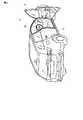
図1は、車両1の構成の一例を示すブロック図である。
図1に示すように、車両1は、ECU(制御手段:Electronic Control Unit)11a、ダンパ12a、回転速度センサ21、シフトポジションセンサ22、静電センサ23、カメラ24、画像処理部25、レーザセンサ26、加速度センサ(取得手段)27、傾斜角センサ(傾斜角検出手段)28、及び電子制御システム29を含み構成される。なお、車両1は、ECU11a、ダンパ12a、回転速度センサ21、シフトポジションセンサ22、静電センサ23、カメラ24、画像処理部25、レーザセンサ26、加速度センサ27、傾斜角センサ28、及び電子制御システム29だけでなく、車両1としての機能を実現するための他の構成(図示省略)も有している。また、図1においては、ECU11a、及びダンパ12aしか図示していないが、車両1に設けられる他の各ドア1bから1dにそれぞれ、ECU11bからECU11d、及びダンパ12bからダンパ12dが設けられている(これらの図示は省略)。つまり、車両1は、4つのドア1aから1dを有するため、ECU、及びダンパを各ドア1aから1dに対応させて4組設けている。FIG. 1 is a block diagram illustrating an example of the configuration of the vehicle 1.
As shown in FIG. 1, the vehicle 1 includes an ECU (Electronic Control Unit) 11a, a
ECU11aは、回転速度センサ21、シフトポジションセンサ22、静電センサ23、画像処理部25、レーザセンサ26、加速度センサ27、傾斜角センサ28、及び電子制御システム29からそれぞれ情報を受信し、これら受信する情報に基づいて、ダンパ12aを制御する。 The ECU 11a receives information from the
より詳細には、ECU11aは、ダンパ12aに含まれる電磁弁の開度を制御する。本実施形態においては、ECU11aは、ダンパ12aの機能を無効にする信号(電磁弁の開度を全開にする指令)、及びダンパ12aの機能を有効にする信号(電磁弁の開度を4分の1、4分の2、4分の3開く指令)をダンパ12aに出力し、ダンパ12aに含まれる電磁弁の開度を制御する。 More specifically, the ECU 11a controls the opening degree of the electromagnetic valve included in the
なお、本実施形態では、ECU11aは、回転速度センサ21、シフトポジションセンサ22、静電センサ23、画像処理部25、レーザセンサ26、加速度センサ27、傾斜角センサ28、及び電子制御システム29からの情報を直接受信する構成を例に挙げて説明するが、車両全体を制御する車両ECUを介してこれらの情報を受信するようにしても良い。 In the present embodiment, the ECU 11 a receives from the
回転速度センサ21は、例えば、車両1の車軸(図示省略)の近傍に設けられ、車軸の回転速度を検出し、検出した回転速度から車両1の車速を算出する。回転速度センサ21は、このように算出した車速をECU11aに出力する。なお、回転速度センサ21は回転速度のみを検出し、この検出結果に基づいて所定の制御部が車両1の車速を算出するようにしても良い。 The
シフトポジションセンサ22は、ドライバから指示されるシフトの位置を検出する。シフトポジションセンサ22は、例えば、ドライバによりパドルノブやシフトレバーが操作され、所定のシフトから他のシフトに移動されたときに、移動された他のシフトの位置を検出する。シフトポジションセンサ22は、検出したシフトの位置をECU11aに出力する。 The
静電センサ(第1のセンサ)23は、例えば、車両1にドア1aを収納したときに、当該ドア1aの縁部を収納する収納部30にユーザが接触しているか否かを検出するセンサである。したがって、静電センサ23は、車両1の車体において、ドアの縁部(ヒンジ部以外の部分)を収納する収納部30に設けられる。 The electrostatic sensor (first sensor) 23 is, for example, a sensor that detects whether or not the user is in contact with the
図2は、静電センサ23の検出領域を概略的に説明するための図である。図2に示すように、収納部30が車両1の右前側面に設けられており、当該収納部30に沿って静電センサ23が設けられる。以下、本実施形態においては、静電センサ23が配置された収納部30をドアオープニング部と称する。 FIG. 2 is a diagram for schematically explaining the detection area of the
静電センサ23は、ユーザの身体の一部(例えば、手や指)が触れた場合に生じる電位の変化に基づいて、ユーザの身体の一部が収納部30に接触しているか否かを検出する。また、静電センサ23は、収納部30にユーザが触れているか否かを示す検出結果をECU11aに出力する。なお、本実施形態においては、収納部30に沿って設けられるセンサは静電センサ23を用いる場合で説明するが、ユーザの身体の一部が接触しているか否かを検出することができるセンサであれば他のセンサを用いても良い。また、車両1の他のドア1bから1dに対応する収納部30にも、同様に、静電センサ23が設けられている。 The
カメラ24は、車室内側及び360度周方向を撮影可能なカメラであり、車両1の車室内の上側に配置される。 The
図3は、カメラ24の検出範囲の一部を概略的に説明するための図である。図3に示すように、ドア1aが開けられている状態においては、カメラ24は、ドア1aを開けた部分を介してドア1aの裏側(車室内側)と車両1の側面との間の領域A1を含めて撮影できるように構成されている。以下、本実施形態において、このドア1aの裏側と車両1の側面との間の領域A1をドアオープニングエリアと称する。また、カメラ24は、撮影した画像を画像処理部25に出力する。なお、カメラ24は、車室内側及び360度方向に撮影可能に構成されているため、ドア1a以外の他のドア1bから1dが開かれた場合も同様に、当該他のドア1bから1dの裏側と、車両1との間の領域を含めて撮影可能になっている。 FIG. 3 is a diagram for schematically explaining a part of the detection range of the
画像処理部25は、カメラ24から入力された画像に対する処理を行う。画像処理部25は、例えば、領域A1の撮影画像に対して、画像処理を行い、物体、例えばユーザが画像内に含まれているかを判断する。画像処理部25は、当該判断結果をECU11aに出力する。 The
本実施形態においては、カメラ24及び画像処理部25により、本発明のドアの裏側から車両1の側面までの間に形成される空間に物体が存在しているか否かを検出するセンサを構成する場合で説明する。なお、ドア1aの裏側から車両1の側面までの間に形成される空間に物体が存在しているか否かを検出することができるセンサであれば、他のセンサを用いても良い。 In this embodiment, the
レーザセンサ26は、車両1が備える左右のバックミラーにそれぞれ設けられる(26a,26b)。レーザセンサ26a,26bは、車両1の側面に存在する物体、及び近づいてくる物体をそれぞれ検出する。 The
図4は、レーザセンサ26a,26bの検出領域を概略的に説明するための図である。図4に示すように、車両1の右側のバックミラーに設けられたレーザセンサ26aが車両1の右側方の領域A2の物体を検出し、車両1の左側のバックミラーに設けられたレーザセンサ26bが車両1の左側方の領域A3の物体を検出する。レーザセンサ26aは、検出結果をECU11a,ECU11bに出力し、レーザセンサ26bは、ECU11c,ECU11dに出力する。 FIG. 4 is a diagram for schematically explaining detection areas of the
加速度センサ27は、高さ方向、幅方向、及び進行方向に移動する車両1の加速度を検出する。加速度センサ27は、検出した加速度をECU11aに出力する。 The
傾斜角センサ28は、水平面に対する高さ方向、幅方向、及び進行方向の車両1の傾斜を検出する。傾斜角センサ28は、検出した傾斜角をECU11aに出力する。 The
電子制御システム29は、車両1が備えるドアロックシステム、ヘッドライト、パワーウインドウ、ワイパー等の電装品を制御し、また、各シートベルトの脱着の状態等を管理するシステムである。本実施形態では、ドアロックシステムは、ドアロックのON/OFFを管理すると共にドア1aから1dの開閉状態を管理する。電子制御システム29は、これら電装品の状態をECU11aに出力する。なお、本実施形態においては、ドアロックシステムが各ドア1aから1dの開閉状態を管理する場合で説明するが、ドア1aから1dの開閉を検出するセンサをそれぞれ設け、当該センサが出力する情報に基づいて、ECU11aから11dがドア1aから1dの開閉をそれぞれ検出するように構成しても良い。 The
ダンパ12aは、ユーザがドア1aを閉じるとき、及び、ドア1aを開けるときの減衰力、言い換えれば、ドア1aの閉じ易さや開け易さを調整する。 The
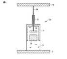
ここで、ダンパ12aの構成について説明する。図5は、ダンパ12aの構成の一例を示す模式図である。本実施形態においては、ダンパ12aとして、電磁弁を有する油圧式のダンパを用いる場合で説明する。なお、他のドア1bから1dに対応するダンパは、ダンパ12aと同一の構成をしているため説明を省略する。 Here, the configuration of the
図5に示すように、ダンパ12aは、筒形状の本体31と、その本体31の先端に設けられた軸受部32とを含み構成されており、本体31内には圧力チャンバー33が形成されている。圧力チャンバー33には、油が充填されている。 As shown in FIG. 5, the
軸受部32内にピストンロッド34が軸方向に移動可能に挿入されており、圧力チャンバー33内に位置するピストンロッド34の先端には、オリフィス35が設けられている。また、圧力チャンバー33内には、オリフィス35と対向するようにピストン36が配置されている。さらに、ピストンロッド34の他端は、ドア1aと直結されており、本体31の基部は車両1の車体2と直結されている。なお、ピストンロッド34の他端が車両1と直結されていて、本体31の基部がドア1aと直結されていても良い。 A
オリフィス35には、電磁弁(図示省略)が設けられている。この電磁弁は、ECU11aから出力される信号に基づいて開度が変更され、ドア1aの開閉時の減衰力を調節可能に構成されている。なお、図5において、ECU11aと電磁弁との間の制御線は図示を省略している。 The
本実施形態においては、ダンパ12aの減衰機能は、有効/無効に設定可能であり、減衰が有効の場合は、3段階(レベルL1、レベルL2、レベルL3)に調整可能に構成されている。 In the present embodiment, the damping function of the
減衰機能が無効に設定されている場合は、ダンパ12aの電磁弁の開度が全開の場合である。この場合、スムーズにドア1aを開閉することができる。レベルL1は、電磁弁が全開に対して3/4閉じた状態にあり、減衰力が最も大きいレベルである。レベルL2は、電磁弁が全開に対して2/4閉じた状態にあり、減衰力が中程度のレベルである。レベルL3は、電磁弁が全開に対して1/4閉じた状態にあり、減衰力が電磁弁全開の場合よりは強いというレベルである。 When the damping function is set to be invalid, the opening degree of the electromagnetic valve of the
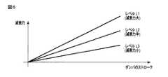
図6は、本実施形態における減衰力のレベルが設定された場合における、減衰力と、ダンパ12aのストロークとの関係を示す図である。 FIG. 6 is a diagram showing the relationship between the damping force and the stroke of the
図6に示すように、ダンパ12aのストローク(ピストンロッド34の移動)が大きくなるにつれて、つまり、ドア1aが車両1に近づく(又は離れる)につれて減衰力が大きくなっている。また、レベルL1、L2,L3に応じてドア1a開閉時の減衰力が大きくなる。 As shown in FIG. 6, the damping force increases as the stroke of the
なお、本実施形態においては、ダンパ12aの減衰力の調整は、レベルL1、レベルL2、レベルL3の3段階の場合で説明するが、減衰力は、後述する第1の所定時間、及び/又は第2の所定時間内においては、検出状態からの経過時間に応じてダンパ12aの減衰力を変化させるようにしても良い。このようにダンパ12aを構成すると、ドア1aの開閉の減衰力を時間に応じて調整することが可能になる。 In the present embodiment, the adjustment of the damping force of the
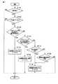
次に、ECU11aが実行する処理について説明する。図7は、ECU11a実行する処理の一例を示すフローチャートである。なお、以下ではドア1aに対するECU11aの処理を一例に挙げて説明するが、車両1の各ドア1bから1dに対して同一の処理が実行される。 Next, processing executed by the ECU 11a will be described. FIG. 7 is a flowchart illustrating an example of processing executed by the ECU 11a. In the following, the processing of the ECU 11a for the
図7に示すように、ECU11aは、車両1が停車中か否かを判断する(ST101)。ECU11aは、回転速度センサ21から送信される車速がゼロか否かで判断するが、車両1の内燃機関又はモータの作動が停止しているか否かやシフトポジションに基づいて、この判断を実行しても良い。 As shown in FIG. 7, the ECU 11a determines whether or not the vehicle 1 is stopped (ST101). The ECU 11a determines whether or not the vehicle speed transmitted from the
停車中であると判断した場合(ST101:YES)、ECU11aは、ドア1aが開いているか否かを判断する(ST102)。例えば、ECU11aは、電子制御システム29のドアロックシステムから取得するドア1aに対応する開閉情報に基づいてドア1aの開閉状態を判断する。 When it is determined that the vehicle is stopped (ST101: YES), the ECU 11a determines whether or not the
ドア1aが開いていると判断した場合(ST102:YES)、ECU11aは、ドアオープニング部検出状態から第1の所定時間以内であるか否かを判断する(ST103)。ここで、ドアオープニング部検出状態とは静電センサ23がユーザの身体の一部を検出している状態であり、第1の所定時間とは静電センサ23がユーザの身体の一部を検出しない状態となったときから予め設定された所定の時間である。 If it is determined that the
ドアオープニング部検出状態から第1の所定時間以内であると判断した場合(ST103:YES)、ECU11aは、減衰機能を有効(レベルL1)に設定する(ST104)。言い換えれば、ECU11aは、電磁弁を3/4閉じた状態にするための信号をダンパ12aに出力する。この信号に基づいて、ダンパ12aの減衰力がレベルL1に設定される。 When it is determined that it is within the first predetermined time from the door opening detection state (ST103: YES), the ECU 11a sets the attenuation function to be valid (level L1) (ST104). In other words, the ECU 11a outputs to the
また、ドアオープニング部検出状態から第1の所定時間以内でないと判断した場合(ST103:NO)、ECU11aは、ドアオープニングエリア検出状態から第2の所定時間以内か否かを判断する(ST106)。ここで、ドアオープニングエリア検出状態とは、画像処理部25から出力される出力結果に基づいて、ドア1aの裏側と、車両1の側面との間に物体(例えば、ユーザ)を検出している状態であり、第2の時間とはドアオープニングエリアで物体を検出しない状態となったときから予め設定された所定の時間である。なお、本実施形態においては、第1の所定時間と第2の所定時間は、同じ時間とするが、異なる時間を設定しても良い。 If it is determined that it is not within the first predetermined time from the door opening portion detection state (ST103: NO), the ECU 11a determines whether it is within the second predetermined time from the door opening area detection state (ST106). Here, in the door opening area detection state, an object (for example, a user) is detected between the back side of the
ドアオープニングエリア検出状態から第2の所定時間以内であると判断した場合(ST105:YES)、ECU11aは、減衰機能を有効(レベルL2)に設定する(ST106)。言い換えれば、ECU11aは、電磁弁を2/4閉じた状態にするための信号をダンパ12aに出力する。この信号に基づいて、ダンパ12aの減衰力がレベルL2に設定される。 When it is determined that it is within the second predetermined time from the door opening area detection state (ST105: YES), the ECU 11a sets the attenuation function to valid (level L2) (ST106). In other words, the ECU 11a outputs a signal for making the
また、ドアオープニングエリア検出状態から第2の所定時間以内でないと判断した場合(ST105:NO)、ECU11aは、車両1に対して吹いている風は風条件に合致しているか否かを判断する(ST107)。ここで、風条件とは、風向がドア1aの閉まる方向と同方向であり、且つ、風速が所定値以上の場合である。また、本実施形態においては、ECU11aは、この判断を風向及び風速を加速度センサ27から出力される情報に基づいて実行する。 Further, when it is determined that it is not within the second predetermined time from the door opening area detection state (ST105: NO), the ECU 11a determines whether or not the wind blowing on the vehicle 1 matches the wind condition. (ST107). Here, the wind condition is a case where the wind direction is the same as the direction in which the
風が風条件に合致していると判断した場合(ST107:YES)、ECU11aは、減衰機能を有効(レベルL3)に設定する(ST108)。言い換えれば、ECU11aは、電磁弁を1/4閉じた状態にするための信号をダンパ12aに出力する。この信号に基づいて、ダンパ12aの減衰力がレベルL3に設定される。 When it is determined that the wind matches the wind condition (ST107: YES), the ECU 11a sets the attenuation function to valid (level L3) (ST108). In other words, the ECU 11a outputs to the
また、風が風条件に合致していないと判断した場合(ST107:NO)、ECU11aは、車両1の傾斜は傾斜条件に合致しているか否かを判断する(ST109)。ここで、傾斜条件とは、ドア1aの閉まる方向に下がるように車両1が所定以上傾斜しているか否かである。また、本実施形態においては、ECU11aは、この判断を傾斜角センサ28から出力される情報に基づいて実行する。 If it is determined that the wind does not match the wind condition (ST107: NO), the ECU 11a determines whether the inclination of the vehicle 1 matches the inclination condition (ST109). Here, the inclination condition is whether or not the vehicle 1 is inclined more than a predetermined amount so as to be lowered in the closing direction of the
傾斜が傾斜条件に合致していると判断した場合(ST109:YES)、ECU11aは、減衰機能を有効(レベルL3)に設定する(ST108)。言い換えれば、ECU11aは、電磁弁を1/4閉じた状態にするための信号をダンパ12aに出力する。これにより、風条件が合致している場合と同様に、ダンパ12aの減衰力がレベルL3に設定される。 When it is determined that the inclination matches the inclination condition (ST109: YES), the ECU 11a sets the attenuation function to valid (level L3) (ST108). In other words, the ECU 11a outputs to the
一方、ECU11aが停車中でないと判断した場合(ST101:NO)、ドア1aが開いていないと判断した場合(ST102:NO)、減衰機能を有効に設定した場合(ST104,ST106,ST108)、又は傾斜角が傾斜角条件に合致しない場合(ST109:NO)、それぞれ処理がリターンとなる。 On the other hand, when the ECU 11a determines that the vehicle is not stopped (ST101: NO), when it is determined that the
次に、ECU11aが実行するダンパ12aの減衰機能を無効に設定する処理について図8から図10を参照して説明する。 Next, a process for setting the damping function of the
図8は、第1の所定時間を経過した場合の処理の一例を示すフローチャートである。
図8に示すように、ECU11aは、第1の所定時間を経過したと判断した場合(ST201:YES)、ECU11aはダンパ12aの減衰機能を無効に設定する(ST202)。言い換えれば、ECU11aは、電磁弁を全開の状態にするための信号をダンパ12aに出力する。FIG. 8 is a flowchart illustrating an example of processing when the first predetermined time has elapsed.
As shown in FIG. 8, when the ECU 11a determines that the first predetermined time has elapsed (ST201: YES), the ECU 11a sets the damping function of the
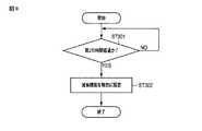
図9は、第2の所定時間を経過した場合の処理の一例を示すフローチャートである。
図9に示すように、ECU11aは、第2の所定時間を経過したと判断した場合(ST301:YES)、ECU11aは、ダンパ12aの減衰機能を無効に設定する(ST302)。言い換えれば、ECU11aは、電磁弁を全開の状態にするための信号をダンパ12aに出力する。FIG. 9 is a flowchart illustrating an example of processing when the second predetermined time has elapsed.
As shown in FIG. 9, when the ECU 11a determines that the second predetermined time has elapsed (ST301: YES), the ECU 11a sets the damping function of the
図10は、ドア1aが閉められた場合の処理の一例を示すフローチャートである。
図10に示すように、ECU11aは、ドア1aが閉められたと判断した場合(ST401:YES)、ECU11aは、ダンパ12aの減衰機能を無効に設定する(ST402)。言い換えれば、ECU11aは、ダンパ12aの電磁弁を全開の状態にするための信号をダンパ12aに出力する。なお、ステップST402の判断を、ECU11aは、電子制御システム29のドアロックシステムから取得するドア1aに対応する情報に基づいて実行する。FIG. 10 is a flowchart illustrating an example of processing when the
As shown in FIG. 10, when the ECU 11a determines that the
以上の図8から図10に示す場合に、ダンパ12aの減衰機能が有効な状態から無効な状態に設定される。 In the case shown in FIGS. 8 to 10, the damping function of the
以上のように構成された車両1は、ドア1aの開閉時の減衰力を調整するダンパ12aと、ドア1aの開閉状態を検出する電子制御システム29のドアロックシステムと、ドア1aの開状態を検出しているときに、ドア1aと車両1の側面との間のユーザの存在を検出するセンサ(静電センサ23、並びにカメラ24及び画像処理部25)と、ユーザの存在を検出した場合、ユーザ存在の検出状態から所定時間(第1の所定時間、第2の所定時間)以内か否かを判断し、所定時間以内である場合にダンパ12aを調整して減衰力をレベルL1、又はレベルL2に変化させるECU11aと、を備えている。 The vehicle 1 configured as described above includes a
したがって、車両1は、ドア1aが閉められるときにユーザの身体の一部をドア1aと車両1の車体との間に挟むことを防止する技術を適切なタイミングで作動させ、安全性及び利便性を確保することができる。 Therefore, the vehicle 1 operates a technique for preventing a part of the user's body from being sandwiched between the
また、静電センサ23は、車両1にドア1aが収納されたときに、ドア1aの縁部を収納する収納部30にユーザ(詳細には、ユーザの手や指等の身体の一部)が接触しているか否かを検出するセンサである。 In addition, when the
このため、例えば、車両1のドア1aを収納する収納部30にユーザの手や指が接触している場合に、当該手や指を検出することができ、当該手や指を検出していた状態から第1の所定時間だけドア1aを閉めるときの減衰力を強くできるため、ドア1aが閉められるときにユーザの手や指を挟むような事態を防止することができ、安全性を向上させることができる。ユーザが子供の場合はドア1aの表側からは子供の姿を視認し難いため、このような状態でドア1aが閉められるときに、特に有効である。 For this reason, for example, when a user's hand or finger is in contact with the
また、カメラ24及び画像処理部25は、ドア1aが開状態にあるときに、ドア1aの裏側から車両1の側面までの間に形成される空間に物体が存在しているか否かを検出するセンサである。 The
このため、例えば、ドア1aが閉められるときに、ドア1aと車両1との間に物体、例えば、ユーザが存在している場合に、当該ユーザを検出していた状態から第2の所定時間だけドア1aを閉めるときの減衰力を強くできるため、ドア1aが閉められるときに、ドア1aユーザに当てる事態を防止することができ、安全性を向上させることができる。ユーザが子供である場合はドア1aの表側からは子供の姿を視認し難いため、このような状態でドア1aが閉められるときに、特に有効であるのは、静電センサ23の場合と同様である。 For this reason, for example, when an object, for example, a user exists between the
また、ECU11aは、静電センサ23によりユーザを検出したときから第1の所定時間以内は、ダンパ12aを調整して減衰力をレベルL1の減衰力に変化させ、カメラ24及び画像処理部25により物体、例えばユーザを検出したときから第2の所定時間以内は、ダンパ12aを調整して減衰力をレベルL1の減衰力より小さいレベルL2の減衰力に変化させ、静電センサ23によるユーザの検出と、カメラ24及び画像処理部25によるユーザの検出とが重なった場合は、減衰力をレベルL1の減衰力に変化させる制御を優先する。 Further, the ECU 11a adjusts the
このため、静電センサ23によるユーザの検出と、カメラ24及び画像処理部25によるユーザの検出とが重なった場合、レベルL1の減衰力(>レベルL2の減衰力)にダンパ12aの減衰力を変化させるため、例えばドア1aに手や指を挟むような危険性がより高い状態を優先するようにダンパ12aの減衰力を設定することができるため、車両1の安全性を向上させることができる。 Therefore, when the detection of the user by the
また、車両1は、車両1周辺の風向及び風速を取得する加速度センサ27を備えており、ECU11aは、ドア1aが開状態であり、第1、及び第2の所定時間以内でないとき、更に、風向が当該ドア1aの閉方向であり、且つ、風速が所定の風速以上である場合、ダンパ12aを調整して減衰力をレベルL2の減衰力より小さいレベルL3の減衰力に変化させる。 Further, the vehicle 1 includes an
このため、静電センサ23によりユーザを検出せず、且つ、カメラ24及び画像処理部25により物体を検出していない状態でも、風向がドア1aを閉める方向と同方向であり、且つ、風速が所定値以上である場合に、ドア1aを閉める減衰力を若干高くすることができる。よって、風の影響によりユーザがドア1aを強く閉めてしまうもしくはユーザが操作していなくてもドアが閉まってしまうという事態を防止することができるため、例えば突然他のユーザがドア1aと車両1との間に入ってきた場合にも、当該ユーザに対する車両1の安全性を確保することができる。 Therefore, even when the
また、車両1は、車両1の傾斜角を検出する傾斜角センサ28を備えており、ECU11aは、ドア1aが開状態であり、第1、及び第2の所定時間以内でないとき、更に、検出される傾斜角がドア1aの閉まる方向と略同方向に下って傾斜している場合、ダンパ12aを調整して減衰力をレベルL2の減衰力より小さいレベルL3の減衰力に変化させる。 Further, the vehicle 1 includes an
このため、静電センサ23によりユーザを検出せず、且つ、カメラ24及び画像処理部25により物体を検出していない状態でも、ドア1aを閉める方向に下がるように車両が傾斜している場合に、ドア1aを閉めるときの減衰力を若干高くすることができる。よって、傾斜の影響によりユーザがドアを強く閉めてしまうもしくはユーザが操作していなくてもドアが閉まってしまうという事態を防止することができきるため、例えば突然他のユーザがドア1aと車両1との間に入ってきた場合にも、当該ユーザに対する車両1の安全性を確保することができる。 For this reason, even when the user is not detected by the
次に、ドア1aが閉まっている状態から開けられるときに実行する処理について説明する。図11は、ドア1aが閉められるときにECU11aが実行する処理の一例を示すフローチャートである。なお、車両1の各ドア1aから1dに対して同一の処理が実行されるが、以下ではドア1aに対する処理を一例に挙げて説明する。図11に示すように、ECU11aは、車両1が停車中か否かを判断する(ST501)。既述のステップST101の処理と同様に、例えば、ECU11aは、この判断を回転速度センサ21から取得する車速がゼロか否かやシフトポジションに基づいて実行する。 Next, processing executed when the
停車中であると判断した場合(ST501:YES)、ECU11aは、ドア1aが閉まっているか否かを判断する(ST502)。例えば、ECU11aは、既述のステップST102の処理と同様に、電子制御システム29のドアロックシステムから取得するドア1aに対応する情報に基づいてドア1aの開閉状態を判断する。 When it is determined that the vehicle is stopped (ST501: YES), the ECU 11a determines whether or not the
ドア1aが閉まっていると判断した場合(ST502:YES)、ECU11aは、ドア1aの車体外側周辺に物体が存在しているか否かを判断する(ST503)。ECU11aは、レーザセンサ26aから取得する情報に基づいてドア1aの車体外周辺に物体が存在しているか否かを判断する。 When it is determined that the
ドア1aの車体外側周辺に物体が存在していると判断した場合(ST503:YES)、ECU11aは、減衰機能を有効(レベルL1)に設定する(ST504)。これにより、ダンパ12aの減衰力がレベルL1に設定される。 If it is determined that an object is present around the outside of the vehicle body of the
また、ドア1aの車体外側周辺に物体が存在していないと判断した場合(ST503:NO)、ECU11aは、車両1の右側後方から近付いてくる物体があるか否かを判断する(ST505)。ECU11aは、この判断を例えば、レーザセンサ26aから取得する情報やカメラ24が撮影する画像の解析結果に基づいて実行する。 Further, when it is determined that no object is present around the outside of the vehicle body of the
車両1の右側後方から近付いている物体があると判断した場合(ST505:YES)、ECU11aは、減衰機能を有効(レベルL2)に設定する(ST506)。これにより、ダンパ12aの減衰力がレベルL2に設定される。 When it is determined that there is an object approaching from the right rear side of the vehicle 1 (ST505: YES), the ECU 11a sets the attenuation function to valid (level L2) (ST506). Thereby, the damping force of the
また、車両1の右側後方から近づいてくる物体が無いと判断した場合(ST505:NO)、ECU11aは、風は風条件に合致したか否か判断する(ST507)。ここで、風条件とは、ステップST107の処理の場合の風条件と同一である。 When it is determined that there is no object approaching from the right rear side of the vehicle 1 (ST505: NO), the ECU 11a determines whether the wind matches the wind condition (ST507). Here, the wind condition is the same as the wind condition in the process of step ST107.
風が風条件に合致していると判断した場合(ST507:YES)、ECU11aは、減衰機能を有効(レベルL3)に設定する(ST508)。これにより、ダンパ12aの減衰力がレベルL3に設定される。 When it is determined that the wind matches the wind condition (ST507: YES), the ECU 11a sets the attenuation function to valid (level L3) (ST508). Thereby, the damping force of the
また、風が風条件に合致していないと判断した場合(ST507:NO)、ECU11aは、傾斜角は傾斜角条件に合致しているか否かを判断する(ST509)。ここで、傾斜角条件は、ステップST509の処理の場合の傾斜角条件と同一である。 If it is determined that the wind does not match the wind condition (ST507: NO), the ECU 11a determines whether or not the tilt angle matches the tilt angle condition (ST509). Here, the tilt angle condition is the same as the tilt angle condition in the case of the process of step ST509.
傾斜角が傾斜角条件に合致していると判断した場合(ST509:YES)、ECU11aは、減衰機能を有効(レベルL3)に設定する(ST508)。これにより、ダンパ12aの減衰力がレベルL3に設定される。 When it is determined that the tilt angle matches the tilt angle condition (ST509: YES), the ECU 11a sets the attenuation function to be valid (level L3) (ST508). Thereby, the damping force of the
一方、ECU11aが停車中でないと判断した場合(ST501:NO)、ドア1aが開いていないと判断した場合(ST502:NO)、減衰機能を有効に設定した場合(ST504,ST506,ST508)、又は傾斜角が傾斜角条件に合致しない場合(ST509:NO)、処理がリターンとなる。 On the other hand, when ECU 11a determines that the vehicle is not stopped (ST501: NO), when it is determined that
車両1は、以上の処理を実行することにより、ドア1aが閉まっている状態から開けられるときに、ドア1aの車体外周辺に物体が存在する場合、ダンパ12aの減衰力をレベルL1に設定することができるため、ドア1aを開く速度を遅くすることができ、ユーザに注意を促すことにより、ドア1aの車体外周辺に停車する他車両や自車両を傷つけることを防止することができる。 By executing the above processing, the vehicle 1 sets the damping force of the
また、右後方から物体、例えば自転車が近づいてくる場合に、車両1は、ダンパ12aの減衰力をレベルL2に設定することができるため、ドア1aを開ける速度を遅くすることができ、例えば自転車を通過させることができるため、ドア1aを開けても自転車の巻き込みを防止することができる。 Further, when an object such as a bicycle approaches from the right rear side, the vehicle 1 can set the damping force of the
さらに、風速が所定値以上である場合や車両1が傾斜している場合に、ダンパ12aの減衰力をレベルL3に設定することができるため、ユーザの想定以上の速さでドア1aが開くことを防止することができる。 Furthermore, since the damping force of the
なお、上記実施形態においては、ドア1aを閉める処理(ST101からST109)、及びドア1aを開ける処理(ST501からST509)について説明したが、車両1の他のドアについても同様な処理を実行することができる。このため、車両1は、車両1の幅方向に開閉されるドア毎に、当該ドアの減衰力の調整を行うことができる。 In the above-described embodiment, the process of closing the
また、上記実施形態においては、ECU11aは、ドアオープニング部検出状態から第1の所定時間以内でない場合に(ST103,ST503:NO)、ECU11aは、ドアオープニングエリア検出状態から第2の所定時間以内であるか否かを判断する場合(ST105,ST505)を説明したが、本発明はこれに限るものではない。ドアオープニング部検出状態から第1の所定時間以内であるか否かの判断(ST103,ST503)のみ、又は、ドアオープニングエリア検出状態から第2の所定時間以内であるか否かの判断(ST105,ST505)のみを行うようにしても良い。 In the above embodiment, when the ECU 11a is not within the first predetermined time from the door opening detection state (ST103, ST503: NO), the ECU 11a is within the second predetermined time from the door opening area detection state. The case of determining whether or not there is (ST105, ST505) has been described, but the present invention is not limited to this. Only whether or not it is within the first predetermined time from the door opening detection state (ST103, ST503), or whether or not it is within the second predetermined time from the door opening area detection state (ST105, ST503) Only ST505) may be performed.
また、風条件に合致しない場合(ST107:NO)に、傾斜角条件に合致するか否かを判断する処理を(ST109)実行する場合で説明したが、本発明は、この条件に限るものではない。ドアオープニングエリア検出状態から第2の所定時間以内でないと判断した場合(ST105:NO)、ECU11aは、風条件のみを判断しても良いし、傾斜角条件のみを判断するようにしても良い。 Further, although the case where the process of determining whether or not the inclination angle condition is met (ST109) is executed when the wind condition is not met (ST107: NO), the present invention is not limited to this condition. Absent. When it is determined that it is not within the second predetermined time from the door opening area detection state (ST105: NO), the ECU 11a may determine only the wind condition or only the inclination angle condition.
さらに、本実施形態において、ドアオープニング部でユーザの身体の一部(例えば、手)を検出しているとき、及びドアオープニングエリアで物体を検出しているときは、ユーザが簡単にドア1aを閉めることができないように構成しても良い。例えば、ECU11aはこのような検出状態にあるときは、ダンパ12aの電磁弁を全閉するように指示を出力してダンパ12aの減衰力をレベルL1の減衰力よりも大きくすることにより、ユーザがドア1aを簡単に閉めることができないようにすれば良い。 Furthermore, in the present embodiment, when a part of the user's body (for example, a hand) is detected by the door opening unit, and when an object is detected by the door opening area, the user can easily open the
この発明は、上述した実施の形態そのままに限定されるものではなく、実施段階ではその要旨を逸脱しない範囲で構成要素を変形して具体化できる。また、上述した実施の形態に開示されている複数の構成要素の適宜な組み合わせにより種々の発明を形成できる。例えば、上述した実施の形態に示される全構成要素から幾つかの構成要素を削除しても良い。さらに、異なる実施形態の構成を組み合わせてもよい。 The present invention is not limited to the above-described embodiments as they are, and can be embodied by modifying the constituent elements without departing from the scope of the invention in the implementation stage. Various inventions can be formed by appropriately combining a plurality of constituent elements disclosed in the above-described embodiments. For example, you may delete some components from all the components shown by embodiment mentioned above. Furthermore, you may combine the structure of different embodiment.
1…車両、1(1aから1d)…ドア、11(11aから11d)…ECU、12(12aから12d)…ダンパ、23…静電センサ、24…カメラ、25…画像処理部、26(26a,26b)…レーザセンサ、27…加速度センサ、28…傾斜角センサ、29…電子制御システム、31…本体、32…軸受部、33…圧力チャンバー、34…ピストンロッド、35…オリフィス、36…ピストン、A1,A2,A3…検出領域、レベルL1,L2,L3…減衰力DESCRIPTION OF SYMBOLS 1 ... Vehicle, 1 (1a to 1d) ... Door, 11 (11a to 11d) ... ECU, 12 (12a to 12d) ... Damper, 23 ... Electrostatic sensor, 24 ... Camera, 25 ... Image processing part, 26 (
Claims (9)
Translated fromJapanese前記ドアの開閉時の減衰力を調整する調整手段と、
前記ドアの開閉状態を検出するドア開閉検出手段と、
前記ドア開閉検出手段により前記ドアの開状態を検出しているときに、前記ドアと前記車両との間のユーザの存在を検出するユーザ検出手段と、
前記ユーザ検出手段により前記ユーザの存在を検出した場合、その検出状態から所定時間以内か否かを判断し、所定時間以内である場合に前記調整手段を調整して前記減衰力を変化させる制御手段と、
を備えることを特徴とする車両用ドア開閉装置。A vehicle door opening and closing device that controls a door that is opened and closed in the width direction of the vehicle,
Adjusting means for adjusting the damping force when the door is opened and closed;
Door opening / closing detecting means for detecting the opening / closing state of the door;
User detection means for detecting the presence of a user between the door and the vehicle when the door open / close detection means is detecting an open state of the door;
When the presence of the user is detected by the user detection means, it is determined whether or not it is within a predetermined time from the detection state, and when it is within the predetermined time, control means for adjusting the adjustment means to change the damping force When,
A vehicle door opening and closing device comprising:
前記検出状態からの経過時間に応じて前記調整手段の前記減衰力を変化させる、
ことを特徴とする請求項1に記載の車両用ドア開閉装置。The control means includes
Changing the damping force of the adjusting means according to the elapsed time from the detection state;
The vehicle door opening and closing device according to claim 1.
前記車両に前記ドアを収納したときに、前記ドアの縁部を収納する収納部にユーザが接触しているか否かを検出するセンサである、
ことを特徴とする請求項1又は請求項2に記載の車両用ドア開閉装置。The user detecting means includes
When the door is stored in the vehicle, it is a sensor that detects whether a user is in contact with a storage unit that stores an edge of the door.
The vehicle door opening and closing device according to claim 1 or 2, characterized in that
前記ドアの裏側から前記車両の側面までの間に形成される空間に物体が存在しているか否かを検出するセンサである、
ことを特徴とする請求項1又は請求項2に記載の車両用ドア開閉装置。The user detecting means includes
A sensor that detects whether an object is present in a space formed between the back side of the door and the side surface of the vehicle;
The vehicle door opening and closing device according to claim 1 or 2, characterized in that
前記車両に前記ドアを収納したときに、前記ドアの縁部を収納する収納部にユーザが接触しているか否かを検出する第1のセンサと、
前記ドアの裏側から前記車両の側面までの間に形成される空間に物体が存在しているか否かを検出する第2のセンサと、
を含み、
前記制御手段は、
前記第1のセンサにより前記ユーザを検出した状態から第1の所定時間以内は、前記調整手段を調整して前記減衰力を第1の減衰力に変化させ、
前記第2のセンサにより前記物体を検出した状態から第2の所定時間以内は、前記調整手段を調整して前記減衰力を第1の減衰力より小さい第2の減衰力に変化させ、
前記第1のセンサによる前記ユーザの検出と、前記第2のセンサによる前記物体の検出とが重なった場合は、前記減衰力を前記第1の減衰力に変化させる制御を優先する、
ことを特徴とする請求項1に記載の車両用ドア開閉装置。The user detecting means includes
A first sensor that detects whether or not a user is in contact with a storage unit that stores an edge of the door when the door is stored in the vehicle;
A second sensor for detecting whether an object exists in a space formed between the back side of the door and the side surface of the vehicle;
Including
The control means includes
Within a first predetermined time from the state in which the user is detected by the first sensor, the adjusting means is adjusted to change the damping force to the first damping force,
Within a second predetermined time from the state in which the object is detected by the second sensor, the adjusting means is adjusted to change the damping force to a second damping force smaller than the first damping force,
When detection of the user by the first sensor and detection of the object by the second sensor overlap, priority is given to control for changing the damping force to the first damping force.
The vehicle door opening and closing device according to claim 1.
を備え、
前記制御手段は、
前記ドアが開状態であり、前記第1の所定時間、及び前記第2の所定時間以内でないとき、更に、前記取得手段により取得する風向が当該ドアの閉方向、且つ、風速が所定の風速以上である場合、前記調整手段を調整して前記減衰力を前記第2の減衰力より小さい第3の減衰力に変化させる、
ことを特徴とする請求項5に記載の車両用ドア開閉装置。Obtaining means for obtaining the wind direction and wind speed around the vehicle;
With
The control means includes
When the door is in an open state and not within the first predetermined time and the second predetermined time, the wind direction acquired by the acquisition means is the closing direction of the door, and the wind speed is equal to or higher than the predetermined wind speed. The adjustment means is adjusted to change the damping force to a third damping force smaller than the second damping force.
The vehicle door opening and closing device according to claim 5.
を備え、
前記制御手段は、
前記ドアが開状態であり、前記第1の所定時間、及び前記第2の所定時間以内でないとき、更に、前記傾斜角検出手段により検出する傾斜が前記ドアの閉まる方向と略同方向に下っている場合、前記調整手段を調整して前記減衰力を前記第2の減衰力より小さい第3の減衰力に変化させる、
ことを特徴とする請求項5に記載の車両用ドア開閉装置。An inclination angle detecting means for detecting an inclination angle of the vehicle;
With
The control means includes
When the door is in an open state and not within the first predetermined time and the second predetermined time, the inclination detected by the inclination angle detecting means is further lowered in the same direction as the door closing direction. And adjusting the adjusting means to change the damping force to a third damping force smaller than the second damping force.
The vehicle door opening and closing device according to claim 5.
前記調整手段、前記ドア開閉検出手段、前記ユーザ検出手段、及び前記制御手段は、複数の前記ドアにそれぞれ設けられ、
前記ドア毎に、当該ドアの減衰力が調整される、
ことを特徴とする請求項1に記載の車両用ドア開閉装置。A plurality of the doors are provided,
The adjustment means, the door opening / closing detection means, the user detection means, and the control means are respectively provided in the plurality of doors,
For each door, the damping force of the door is adjusted.
The vehicle door opening and closing device according to claim 1.
前記制御手段は、前記電磁弁の開度を制御することにより油圧を調整して前記減衰力を変化させる、
ことを特徴とする請求項1から請求項8のいずれか一項に記載の車両用ドア開閉装置。The adjusting means is a hydraulic damper having a solenoid valve,
The control means adjusts the hydraulic pressure by controlling the opening of the electromagnetic valve to change the damping force;
The vehicle door opening and closing device according to any one of claims 1 to 8, wherein the vehicle door opening and closing device is provided.
Priority Applications (1)
| Application Number | Priority Date | Filing Date | Title |
|---|---|---|---|
| JP2016032988AJP6623825B2 (en) | 2016-02-24 | 2016-02-24 | Vehicle door opening and closing device |
Applications Claiming Priority (1)
| Application Number | Priority Date | Filing Date | Title |
|---|---|---|---|
| JP2016032988AJP6623825B2 (en) | 2016-02-24 | 2016-02-24 | Vehicle door opening and closing device |
Publications (2)
| Publication Number | Publication Date |
|---|---|
| JP2017149246Atrue JP2017149246A (en) | 2017-08-31 |
| JP6623825B2 JP6623825B2 (en) | 2019-12-25 |
Family
ID=59740337
Family Applications (1)
| Application Number | Title | Priority Date | Filing Date |
|---|---|---|---|
| JP2016032988AExpired - Fee RelatedJP6623825B2 (en) | 2016-02-24 | 2016-02-24 | Vehicle door opening and closing device |
Country Status (1)
| Country | Link |
|---|---|
| JP (1) | JP6623825B2 (en) |
Cited By (3)
| Publication number | Priority date | Publication date | Assignee | Title |
|---|---|---|---|---|
| CN108868453A (en)* | 2018-06-13 | 2018-11-23 | 佛山市澄澜点寸科技有限公司 | A kind of automatically-controlled door time switch machine control system and control method |
| KR20200004074A (en)* | 2018-07-03 | 2020-01-13 | 현대자동차주식회사 | System and method for controlling of safety power window |
| CN115898168A (en)* | 2022-10-31 | 2023-04-04 | 东风汽车集团股份有限公司 | Control method, device and equipment for automobile electric door lock and storage medium |
Citations (6)
| Publication number | Priority date | Publication date | Assignee | Title |
|---|---|---|---|---|
| JPS57126717A (en)* | 1981-01-30 | 1982-08-06 | Mazda Motor Corp | Door opening and closing assisting unit |
| JPS6121824A (en)* | 1984-07-10 | 1986-01-30 | Nippon Denso Co Ltd | Car door opening/closing force compensating device |
| JP2004027824A (en)* | 2002-04-25 | 2004-01-29 | Aisin Seiki Co Ltd | In-vehicle door operation system |
| US20080001563A1 (en)* | 2006-06-20 | 2008-01-03 | Aisin Seiki Kabushiki Kaisha | Control apparatus for opening/closing member of vehicle and control method for opening/closing member of vehicle |
| JP2009041209A (en)* | 2007-08-07 | 2009-02-26 | Equos Research Co Ltd | Vehicle door system |
| JP2009221798A (en)* | 2008-03-18 | 2009-10-01 | Mitsuba Corp | Drive control unit for opening and closing body of vehicle |
- 2016
- 2016-02-24JPJP2016032988Apatent/JP6623825B2/ennot_activeExpired - Fee Related
Patent Citations (6)
| Publication number | Priority date | Publication date | Assignee | Title |
|---|---|---|---|---|
| JPS57126717A (en)* | 1981-01-30 | 1982-08-06 | Mazda Motor Corp | Door opening and closing assisting unit |
| JPS6121824A (en)* | 1984-07-10 | 1986-01-30 | Nippon Denso Co Ltd | Car door opening/closing force compensating device |
| JP2004027824A (en)* | 2002-04-25 | 2004-01-29 | Aisin Seiki Co Ltd | In-vehicle door operation system |
| US20080001563A1 (en)* | 2006-06-20 | 2008-01-03 | Aisin Seiki Kabushiki Kaisha | Control apparatus for opening/closing member of vehicle and control method for opening/closing member of vehicle |
| JP2009041209A (en)* | 2007-08-07 | 2009-02-26 | Equos Research Co Ltd | Vehicle door system |
| JP2009221798A (en)* | 2008-03-18 | 2009-10-01 | Mitsuba Corp | Drive control unit for opening and closing body of vehicle |
Cited By (4)
| Publication number | Priority date | Publication date | Assignee | Title |
|---|---|---|---|---|
| CN108868453A (en)* | 2018-06-13 | 2018-11-23 | 佛山市澄澜点寸科技有限公司 | A kind of automatically-controlled door time switch machine control system and control method |
| KR20200004074A (en)* | 2018-07-03 | 2020-01-13 | 현대자동차주식회사 | System and method for controlling of safety power window |
| KR102610321B1 (en)* | 2018-07-03 | 2023-12-06 | 현대자동차주식회사 | System and method for controlling of safety power window |
| CN115898168A (en)* | 2022-10-31 | 2023-04-04 | 东风汽车集团股份有限公司 | Control method, device and equipment for automobile electric door lock and storage medium |
Also Published As
| Publication number | Publication date |
|---|---|
| JP6623825B2 (en) | 2019-12-25 |
Similar Documents
| Publication | Publication Date | Title |
|---|---|---|
| US7411364B2 (en) | Window opening and closing controller | |
| JP6409212B2 (en) | Power door opener | |
| EP3297278B1 (en) | Vehicular visual recognition device | |
| US20160300473A1 (en) | Vehicle door opening warning system and vehicle door opening warning method | |
| US9617777B2 (en) | Vehicle window opening device | |
| US9751462B2 (en) | Vehicle and vehicle door clearance notification system | |
| JP6623825B2 (en) | Vehicle door opening and closing device | |
| US20190193633A1 (en) | Viewing device for vehicle | |
| CN104340129A (en) | Operating apparatus and operating control method of side step of vehicle | |
| JP2009299387A (en) | Opening/closing body controller | |
| JP4349041B2 (en) | Pedestrian protection device | |
| CN115107442A (en) | A vehicle control method and device | |
| JP6730612B2 (en) | Vehicle display control device, vehicle display control system, vehicle display control method and program | |
| KR20170032597A (en) | Auxiliary step for rotating in association with door and control method thereof | |
| JP2007284958A (en) | Sliding door device | |
| US20180229660A1 (en) | Image display device | |
| JP6905404B2 (en) | Pinching detection device and opening / closing system | |
| JP2016117430A (en) | Vehicle visibility control device | |
| JP6385808B2 (en) | Visual control device for vehicle | |
| CN114872625A (en) | Door-opening rearview mirror follow-up control method | |
| KR102146658B1 (en) | Device for controlling a position of seat for convenience of getting on and off of the passenger and method thereof | |
| JP7083577B2 (en) | Vehicle door closer device | |
| TWI592322B (en) | Vehicle door opening warning system and vehicle door opening warning method | |
| JP2024135602A (en) | vehicle | |
| JP2007063893A (en) | Vehicle door control device |
Legal Events
| Date | Code | Title | Description |
|---|---|---|---|
| A621 | Written request for application examination | Free format text:JAPANESE INTERMEDIATE CODE: A621 Effective date:20181221 | |
| TRDD | Decision of grant or rejection written | ||
| A01 | Written decision to grant a patent or to grant a registration (utility model) | Free format text:JAPANESE INTERMEDIATE CODE: A01 Effective date:20191029 | |
| A977 | Report on retrieval | Free format text:JAPANESE INTERMEDIATE CODE: A971007 Effective date:20191031 | |
| A61 | First payment of annual fees (during grant procedure) | Free format text:JAPANESE INTERMEDIATE CODE: A61 Effective date:20191111 | |
| R151 | Written notification of patent or utility model registration | Ref document number:6623825 Country of ref document:JP Free format text:JAPANESE INTERMEDIATE CODE: R151 | |
| LAPS | Cancellation because of no payment of annual fees |