JP2017147677A - External auditory canal insertion unit - Google Patents
External auditory canal insertion unitDownload PDFInfo
- Publication number
- JP2017147677A JP2017147677AJP2016029758AJP2016029758AJP2017147677AJP 2017147677 AJP2017147677 AJP 2017147677AJP 2016029758 AJP2016029758 AJP 2016029758AJP 2016029758 AJP2016029758 AJP 2016029758AJP 2017147677 AJP2017147677 AJP 2017147677A
- Authority
- JP
- Japan
- Prior art keywords
- annular flange
- elastic member
- ear canal
- annular
- ear
- Prior art date
- Legal status (The legal status is an assumption and is not a legal conclusion. Google has not performed a legal analysis and makes no representation as to the accuracy of the status listed.)
- Pending
Links
- 210000000613ear canalAnatomy0.000titleclaimsabstractdescription135
- 238000003780insertionMethods0.000titleclaimsabstractdescription56
- 230000037431insertionEffects0.000titleclaimsabstractdescription56
- 239000000463materialSubstances0.000claimsdescription14
- 238000007789sealingMethods0.000abstractdescription12
- 230000002093peripheral effectEffects0.000description52
- 230000004048modificationEffects0.000description32
- 238000012986modificationMethods0.000description32
- 210000000883ear externalAnatomy0.000description14
- 230000000694effectsEffects0.000description7
- JOYRKODLDBILNP-UHFFFAOYSA-NEthyl urethaneChemical compoundCCOC(N)=OJOYRKODLDBILNP-UHFFFAOYSA-N0.000description4
- 238000005259measurementMethods0.000description4
- 125000004122cyclic groupChemical class0.000description3
- 229920001971elastomerPolymers0.000description3
- 239000007779soft materialSubstances0.000description3
- 210000003454tympanic membraneAnatomy0.000description3
- YLQBMQCUIZJEEH-UHFFFAOYSA-NFuranChemical compoundC=1C=COC=1YLQBMQCUIZJEEH-UHFFFAOYSA-N0.000description2
- 241000746998TragusSpecies0.000description2
- 230000007423decreaseEffects0.000description2
- 239000000806elastomerSubstances0.000description2
- 229920002379silicone rubberPolymers0.000description2
- 239000004945silicone rubberSubstances0.000description2
- 239000000758substrateSubstances0.000description2
- XAGFODPZIPBFFR-UHFFFAOYSA-NaluminiumChemical compound[Al]XAGFODPZIPBFFR-UHFFFAOYSA-N0.000description1
- 229910052782aluminiumInorganic materials0.000description1
- 230000006866deteriorationEffects0.000description1
- 230000001105regulatory effectEffects0.000description1
- 229920005989resinPolymers0.000description1
- 239000011347resinSubstances0.000description1
- 239000003566sealing materialSubstances0.000description1
- 229920002050silicone resinPolymers0.000description1
- 238000009423ventilationMethods0.000description1
Images


Landscapes
- Headphones And Earphones (AREA)
Abstract
Description
Translated fromJapanese本願発明は、イヤーチップを外耳道に挿入した状態で使用するように構成された外耳道挿入型ユニットに関するものである。 The present invention relates to an ear canal insertion type unit configured to be used with an ear tip inserted into the ear canal.
従来より、被検者の生体音を測定するための生体音測定システムとして、被検者の外耳道を密閉してその内圧変化から生体信号を測定するように構成されたものが知られており、その測定のためのセンサユニットも知られている。 Conventionally, as a body sound measurement system for measuring a subject's body sound, what is configured to measure a body signal from a change in internal pressure by sealing the subject's external ear canal, Sensor units for the measurement are also known.
このセンサユニットは、補聴器や挿入型イヤホンと同様、外耳道挿入型ユニットとして構成されている。すなわち、この外耳道挿入型ユニットは、ユニット本体の音導管とこれに装着されたイヤーチップとで音導孔を形成するように構成されており、そのイヤーチップを外耳道に挿入した状態で使用するように構成されている。 This sensor unit is configured as an external ear canal insertion type unit, like a hearing aid and an insertion type earphone. That is, this ear canal insertion type unit is configured to form a sound guide hole with the sound conduit of the unit main body and the ear tip attached thereto, and is used in a state where the ear tip is inserted into the ear canal. It is configured.
「特許文献1」には、このような外耳道挿入型ユニットとして、環状フランジ部が2重に配置されたイヤーチップを備えた挿入型イヤホンが記載されている。 “Patent Document 1” describes an insertion-type earphone including an ear tip in which an annular flange portion is doubled as such an external ear canal insertion-type unit.
すなわち、この「特許文献1」に記載された外耳道挿入型ユニットのイヤーチップは、基端部において音導管に装着された筒状部と、この筒状部の先端部から基端部側へ向けて広がるように形成された第1環状フランジ部と、筒状部の中間部から基端部側へ向けて広がるように形成された第2環状フランジ部とを備えた構成となっている。 In other words, the ear tip of the ear canal insertion type unit described in “Patent Document 1” includes a cylindrical portion attached to the sound conduit at the base end portion, and from the distal end portion of the cylindrical portion toward the proximal end portion side. 1st annular flange part formed so that it may spread, and it has the composition provided with the 2nd annular flange part formed so that it may spread toward the base end side from the middle part of a cylindrical part.
一方「特許文献2」には、外耳道挿入型ユニットのような音導孔を備えていない減音イヤープラグの構成として、ステム(「筒状部」に相当)とこのステムの3箇所からその基端部側へ向けて広がるようにして配置された3重のサポート(「環状フランジ部」に相当)とこれらを外周側から覆うシェルとを備えたものが記載されている。 On the other hand, “Patent Document 2” describes a configuration of a sound-reducing ear plug that does not have a sound conducting hole as in the external ear canal insertion type unit, and is based on a stem (corresponding to a “cylindrical portion”) and three parts of the stem. There is described a triple support (corresponding to an “annular flange portion”) arranged so as to spread toward the end side and a shell covering these from the outer peripheral side.
上記「特許文献1」に記載された外耳道挿入型ユニットにおいては、第1および第2環状フランジ部の各々がその全周にわたって外耳道壁に接触することにより、外耳道に対する密閉性と安定した装着状態とを確保することが可能である。 In the ear canal insertion type unit described in the above-mentioned “Patent Document 1”, each of the first and second annular flange portions comes into contact with the ear canal wall over the entire circumference thereof, so that the sealability to the ear canal and a stable wearing state are obtained. Can be secured.
しかしながら、外耳道形状には個人差があるため、イヤーチップの第1および第2環状フランジ部が変形しきれずに、その全周にわたって外耳道壁に接触できない場合が生じ得る。このような場合には、空気漏れが発生してしまい、生体信号の測定不可能や音響信号の音質低下などの事態が生じ得る。 However, since there are individual differences in the external auditory canal shape, the first and second annular flange portions of the ear tip may not be fully deformed and may not be able to contact the external auditory canal wall over the entire circumference. In such a case, air leakage may occur, and a situation such as inability to measure a biological signal or deterioration in sound quality of an acoustic signal may occur.
また、イヤーチップを外耳道に挿入したとき、その筒状部における第1および第2環状フランジ部との間の部分が屈曲してしまったような場合には、その弾力性によって筒状部が元の形状に戻ろうとするので、イヤーチップの挿入位置が変化したり、イヤーチップが外耳道から抜けたりしてしまう事態が生じ得る。 In addition, when the ear tip is inserted into the ear canal, when the portion between the first and second annular flange portions in the tubular portion is bent, the tubular portion is restored due to its elasticity. Therefore, a situation may occur in which the insertion position of the ear tip changes or the ear tip falls out of the ear canal.
一方、上記「特許文献2」に記載された減音イヤープラグに対して音導孔を形成することにより、外耳道挿入型ユニットとしての利用を図るようにすることも考えられるが、この減音イヤープラグにおいては、そのシェルがステムの先端部も覆っているので、ステムとシェルとの間で音導孔の位置ずれが発生したり、シェルに形成された音導孔の変形などが発生してしまうおそれがある。 On the other hand, it is conceivable that a sound guide hole is formed in the sound-reducing ear plug described in the above-mentioned “Patent Document 2” so that it can be used as an ear canal insertion type unit. In the plug, since the shell also covers the tip of the stem, the position of the sound guide hole is displaced between the stem and the shell, or the sound guide hole formed in the shell is deformed. There is a risk that.
また、この減音イヤープラグにおいては、そのシェルがサポートと3重に配置されたステムとを外周側から覆うように配置されているため、シェルもサポートやステムの影響を受けた変形をしてしまい、外耳道に対する密閉性を確保することが容易でない。 In this sound-reducing earplug, since the shell is arranged so as to cover the support and the triple arranged stem from the outer peripheral side, the shell is also deformed by the influence of the support and the stem. Therefore, it is not easy to ensure the sealing property to the external auditory canal.
さらに、この減音イヤープラグにおいては、これを外耳道から取り外す際にシェルがサポートから外れてしまうおそれがある。 Furthermore, in this sound-reducing earplug, there is a possibility that the shell may come off from the support when it is removed from the ear canal.
本願発明は、このような事情に鑑みてなされたものであって、イヤーチップを外耳道に挿入した状態で使用するように構成された外耳道挿入型ユニットにおいて、外耳道形状の個人差を加味した上で、外耳道に対する密閉性と安定した装着状態とを確保することができる外耳道挿入型ユニットを提供することを目的とするものである。 The present invention has been made in view of such circumstances, and in the ear canal insertion type unit configured to be used in a state where the ear tip is inserted into the ear canal, in consideration of individual differences in the ear canal shape. An object of the present invention is to provide an external auditory canal insertion type unit that can ensure sealing performance with respect to the external auditory canal and a stable wearing state.
本願発明は、環状フランジ部が多重に配置されたイヤーチップを採用した上で、その所定部位に環状弾性部材が装着された構成とすることにより、上記目的達成を図るようにしたものである。 The present invention is intended to achieve the above object by adopting a configuration in which an annular tip is provided in multiple positions and an annular elastic member is attached to a predetermined portion thereof.
すなわち、本願発明に係る外耳道挿入型ユニットは、
音導管を有するユニット本体と、このユニット本体の音導管に装着されたイヤーチップとを備えてなり、上記イヤーチップを外耳道に挿入した状態で使用するように構成された外耳道挿入型ユニットにおいて、
上記イヤーチップは、基端部において上記音導管に装着されることにより該音導管とで音導孔を形成する筒状部と、この筒状部の所要部位から上記基端部側へ向けて広がるように形成された第1環状フランジ部と、上記筒状部における上記所要部位よりも上記基端部側の部位から上記基端部側へ向けて広がるように形成された第2環状フランジ部とを備えており、
上記第1環状フランジ部の外径よりも小さい内径でかつ該第1環状フランジ部の外径よりも大きい外径を有する環状弾性部材が、上記第1環状フランジ部と上記第2環状フランジ部との間において上記イヤーチップに装着されている、ことを特徴とするものである。That is, the ear canal insertion type unit according to the present invention is
In an ear canal insertion type unit comprising a unit main body having a sound conduit and an ear tip attached to the sound conduit of the unit main body and configured to be used in a state where the ear tip is inserted into the ear canal.
The ear tip is attached to the sound conduit at a base end portion to form a sound guide hole with the sound conduit, and from a required part of the cylindrical portion toward the base end side. A first annular flange portion formed so as to expand, and a second annular flange portion formed so as to spread from the base end side portion toward the base end portion side with respect to the required portion in the tubular portion. And
An annular elastic member having an inner diameter smaller than the outer diameter of the first annular flange portion and an outer diameter larger than the outer diameter of the first annular flange portion includes the first annular flange portion and the second annular flange portion. It is equipped with the said ear chip | tip in the meantime.
上記「外耳道挿入型ユニット」は、そのイヤーチップを外耳道に挿入した状態で使用されるものであれば、その具体的な用途は特に限定されるものではなく、例えば、生体信号を測定するためのセンサユニットや補聴器あるいは挿入型イヤホン等が採用可能である。 As long as the above-mentioned “ear canal insertion type unit” is used in a state in which the ear tip is inserted into the ear canal, its specific application is not particularly limited. For example, for measuring a biological signal A sensor unit, a hearing aid, an insertion type earphone, or the like can be employed.
上記「イヤーチップ」は、第1および第2環状フランジ部が2重に配置された構成となっているが、新たな環状フランジ部の追加により環状フランジ部が3重以上に配置された構成となっていてもよい。 The above-mentioned “ear tip” has a configuration in which the first and second annular flange portions are arranged in a double manner, and a configuration in which the annular flange portions are arranged in a triple or more by adding a new annular flange portion, and It may be.
上記「第1環状フランジ部」は、筒状部の所要部位からその基端部側へ向けて広がるように形成されているが、その具体的な形状や「所要部位」の具体的な位置等は特に限定されるものではない。 The “first annular flange portion” is formed so as to spread from the required portion of the cylindrical portion toward the base end side, but the specific shape, the specific position of the “required portion”, etc. Is not particularly limited.
上記「第2環状フランジ部」は、上記所要部位よりも基端部側の部位から基端部側へ向けて広がるように形成されているが、その具体的な形状や「所要部位よりも基端部側の部位」の具体的な位置等は特に限定されるものではない。 The “second annular flange portion” is formed so as to spread from the base end side portion toward the base end portion side relative to the required portion, but the specific shape and the A specific position or the like of the “end portion side portion” is not particularly limited.
上記「環状弾性部材」は、第1環状フランジ部の外径よりも小さい内径でかつその外径よりも大きい外径を有するものであれば、その具体的な形状は特に限定されるものではない。また、この「環状弾性部材」は、弾性部材として構成されていれば、イヤーチップの硬度よりも低い硬度の材質で構成されてよいし同等または高い硬度の材質で構成されていてもよい。さらに、この「環状弾性部材」は、イヤーチップに装着された状態において環状に形成された構成となっていれば、装着前の状態では必ずしも環状に形成されていなくてもよい。 As long as the “annular elastic member” has an inner diameter smaller than the outer diameter of the first annular flange portion and an outer diameter larger than the outer diameter, the specific shape is not particularly limited. . In addition, as long as the “annular elastic member” is configured as an elastic member, it may be formed of a material having a hardness lower than that of the ear tip, or may be formed of a material having the same or higher hardness. Further, the “annular elastic member” does not necessarily have to be formed in a ring shape before being mounted as long as it is configured to be formed in a ring shape when mounted on the ear tip.
本願発明に係る外耳道挿入型ユニットは、そのイヤーチップが、基端部において音導管に装着された筒状部と、その所要部位から基端部側へ向けて広がるように形成された第1環状フランジ部と、その所要部位よりも基端部側の部位から基端部側へ向けて広がるように形成された第2環状フランジ部とを備えた構成となっているが、このイヤーチップに対して、第1環状フランジ部の外径よりも小さい内径でかつその外径よりも大きい外径を有する環状弾性部材が、第1環状フランジ部と第2環状フランジ部との間において装着された構成となっているので、次のような作用効果を得ることができる。 The ear canal insertion type unit according to the present invention includes a cylindrical portion attached to the sound conduit at the proximal end portion and a first annular shape formed so as to spread from the required portion toward the proximal end portion. Although it has a configuration including a flange portion and a second annular flange portion formed so as to spread from the portion closer to the base end side toward the base end portion side than the required portion, An annular elastic member having an inner diameter smaller than the outer diameter of the first annular flange portion and an outer diameter larger than the outer diameter is mounted between the first annular flange portion and the second annular flange portion. Therefore, the following effects can be obtained.
すなわち、イヤーチップを外耳道に挿入したとき、第1環状フランジ部をその全周にわたって外耳道壁に接触させるとともに、この第1環状フランジ部の外径よりも大きい外径を有する環状弾性部材を、第2環状フランジ部に押し当てられた状態で、あるいは第2環状フランジ部から離れた状態で、その全周にわたって外耳道壁に接触させることができる。そしてこれにより、イヤーチップを外耳道に挿入したとき、外耳道に対する密閉性と安定した装着状態とが得られるようにすることができる。 That is, when the ear tip is inserted into the ear canal, the first annular flange portion is brought into contact with the outer ear canal wall over the entire circumference, and an annular elastic member having an outer diameter larger than the outer diameter of the first annular flange portion is The outer ear canal wall can be brought into contact with the entire circumference in a state of being pressed against the two annular flange portions or being separated from the second annular flange portion. As a result, when the ear tip is inserted into the ear canal, it is possible to obtain a sealing property with respect to the ear canal and a stable wearing state.
その際、環状弾性部材はイヤーチップとは別の部材として構成されているので、外耳道形状に個人差があるために第1および第2環状フランジ部が変形しきれないような場合あるいは筒状部における第1および第2環状フランジ部との間の部分が屈曲してしまったような場合であっても、環状弾性部材を外耳道壁に対してその全周にわたって確実に接触させるようにすることができる。そしてこれにより、外耳道におけるイヤーチップの挿入位置が変化したりイヤーチップが外耳道から抜けたりしてしまうのを未然に防止することができる。 At that time, since the annular elastic member is configured as a member different from the ear tip, the first and second annular flange portions cannot be fully deformed due to individual differences in the external auditory canal shape or the cylindrical portion. Even when the portion between the first and second annular flange portions in the case has been bent, the annular elastic member is reliably brought into contact with the outer ear canal wall over the entire circumference thereof. it can. As a result, it is possible to prevent the ear tip insertion position in the ear canal from changing or the ear tip from coming out of the ear canal.
また、環状弾性部材は、第1環状フランジ部と第2環状フランジ部との間においてイヤーチップに装着されており、かつ、その内径は第1環状フランジ部の外径よりも小さいので、イヤーチップを外耳道から取り外す際、その第1環状フランジ部との係合作用によって環状弾性部材がイヤーチップから不用意に外れてしまわないようにすることができる。そしてこれにより、外れ防止のために環状弾性部材をイヤーチップに接着したり固定構造を設けたりする必要をなくすことができる。 The annular elastic member is attached to the ear tip between the first annular flange portion and the second annular flange portion, and the inner diameter thereof is smaller than the outer diameter of the first annular flange portion. When removing from the ear canal, it is possible to prevent the annular elastic member from being inadvertently detached from the ear tip by the engaging action with the first annular flange portion. Thereby, it is possible to eliminate the need to bond the annular elastic member to the ear tip or to provide a fixing structure in order to prevent detachment.
このように本願発明によれば、イヤーチップを外耳道に挿入した状態で使用するように構成された外耳道挿入型ユニットにおいて、外耳道形状の個人差を加味した上で、外耳道に対する密閉性と安定した装着状態とを確保することができる。 そしてこれにより、生体信号を測定する際の測定精度の向上や音響信号の音質改善を図ることができ、かつ、イヤーチップを長時間装着した場合であっても違和感の少ない快適な装着状態を維持することができる。 As described above, according to the present invention, in the ear canal insertion type unit configured to be used in a state where the ear tip is inserted into the ear canal, taking into account individual differences in the shape of the ear canal, the sealing property with respect to the ear canal and stable wearing State can be secured. This makes it possible to improve the measurement accuracy when measuring biological signals and improve the sound quality of acoustic signals, and maintain a comfortable wearing state with little discomfort even when the eartip is worn for a long time. can do.
また、本願発明に係る外耳道挿入型ユニットにおいては、環状弾性部材がイヤーチップとは別の部材として構成されているので、この環状弾性部材として、その形状や肉厚等が異なるものを複数種類用意しておき、これらを適宜取り替えるようにすれば、外耳道形状の個人差に対応することが一層容易に可能となる。 In the ear canal insertion type unit according to the present invention, since the annular elastic member is configured as a member different from the ear tip, a plurality of types having different shapes and thicknesses are prepared as the annular elastic member. In addition, if these are appropriately replaced, it becomes easier to cope with individual differences in the external auditory canal shape.
上記構成において、環状弾性部材をイヤーチップよりも硬度が低い材質で構成されたものとすれば、これを外耳道壁に対してその全周にわたって確実に接触させることが一層容易に可能となる。しかも、イヤーチップを外耳道に挿入してから一定の時間が経過したとき、環状弾性部材を外耳道形状に沿って変形した状態で安定させることが可能となり、これにより違和感の少ない快適な装着状態を維持することが一層容易に可能となる。また、このような構成を採用することにより、イヤーチップに対する環状弾性部材の着脱を一層容易に行うことが可能となる。 In the above configuration, if the annular elastic member is made of a material whose hardness is lower than that of the ear tip, it can be more easily made to reliably contact the outer ear canal wall over the entire circumference. In addition, when a certain amount of time has passed since the eartip was inserted into the ear canal, the annular elastic member can be stabilized in a deformed state along the shape of the ear canal, thereby maintaining a comfortable wearing state with less discomfort. This can be done more easily. Also, by adopting such a configuration, it becomes possible to more easily attach and detach the annular elastic member to and from the ear tip.
上記構成において、環状弾性部材を、筒状部の基端部側へ向けて広がるように形成された構成とすれば、これを第2環状フランジ部に対して広範囲にわたって密着させることが容易に可能となり、これにより環状弾性部材を外耳道壁に対してその全周にわたって確実に接触させることが一層容易に可能となる。 In the above configuration, if the annular elastic member is formed so as to spread toward the base end side of the tubular portion, it can be easily adhered to the second annular flange portion over a wide range. Thus, the annular elastic member can be more easily brought into contact with the outer ear canal wall with certainty over its entire circumference.
その際、環状弾性部材を第2環状フランジ部よりも大きい外径を有する構成とすれば、これを外耳道壁に対してその全周にわたって確実に接触させることがより一層容易に可能となる。 At this time, if the annular elastic member has a larger outer diameter than the second annular flange portion, it can be more easily made to reliably contact the outer ear canal wall over the entire circumference.
上記構成において、環状弾性部材のイヤーチップに対する装着が、筒状部が延びる方向に移動可能な態様で行われる構成とすれば、イヤーチップを外耳道に挿入したとき環状弾性部材を外耳道形状に追従させることが容易に可能となり、これにより外耳道形状の個人差に適切に対応することが一層容易に可能となる。 In the above configuration, if the annular elastic member is attached to the ear tip in a manner that is movable in the direction in which the cylindrical portion extends, the annular elastic member follows the shape of the ear canal when the ear tip is inserted into the ear canal. This makes it easier to appropriately cope with individual differences in the external auditory canal shape.
上記構成において、第2環状フランジ部を第1環状フランジ部よりも大きい外径を有する構成とすれば、この第2環状フランジ部に押し当てられた環状弾性部材を外耳道壁に対してその全周にわたって確実に接触させることが一層容易に可能となる。 In the above configuration, when the second annular flange portion has a larger outer diameter than the first annular flange portion, the entire circumference of the annular elastic member pressed against the second annular flange portion with respect to the outer ear canal wall is set. It is possible to more reliably make contact with each other.
上記構成において、ユニット本体における音導管側の端部に、第2環状フランジ部よりも大きい外径を有する第2の環状弾性部材が装着された構成すれば、次のような作用効果を得ることができる。 In the above configuration, if the second annular elastic member having an outer diameter larger than that of the second annular flange portion is attached to the end portion of the unit main body on the sound conduit side, the following effects can be obtained. Can do.
すなわち、イヤーチップを外耳道に挿入したとき、ユニット本体は外耳道の入り口の耳甲介の空間に位置することとなるが、その際、このユニット本体に装着された第2の環状弾性部材は耳甲介の空間に嵌め込まれるようにして配置されることとなるので、ユニット本体は耳甲介の部分に安定的に保持されることとなる。 That is, when the ear tip is inserted into the ear canal, the unit main body is located in the space of the concha at the entrance of the ear canal. At this time, the second annular elastic member attached to the unit main body is the ear annular. Therefore, the unit main body is stably held by the concha portion.
したがって、イヤーチップを外耳道に挿入したとき、外耳道に対する密閉性と安定した装着状態とを確保することがより一層容易に可能となる。 Therefore, when the ear tip is inserted into the ear canal, it is possible to more easily ensure the sealing property with respect to the ear canal and the stable wearing state.
以下、図面を用いて、本願発明の実施の形態について説明する。 Hereinafter, embodiments of the present invention will be described with reference to the drawings.
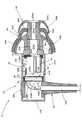
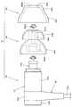
図1は、本願発明の一実施形態に係る外耳道挿入型ユニット10を、右向きに配置した状態で示す側断面図である。また、図2は、この外耳道挿入型ユニット10を、その主要構成要素に分解して示す側面図である。 FIG. 1 is a side sectional view showing an external auditory canal
これらの図に示すように、本実施形態に係る外耳道挿入型ユニット10は、音導管20Aを有するユニット本体20と、その音導管20Aに装着されたイヤーチップ50と、このイヤーチップ50に装着された環状弾性部材60とを備えた構成となっている。 As shown in these drawings, the external auditory canal
そして、この外耳道挿入型ユニット10は、そのイヤーチップ50を被検者の外耳道に挿入した状態で、脈拍音等の生体音を収音するために用いられるようになっている。 The ear canal
ユニット本体20は、筐体22内にマイクロホンユニット24およびスピーカユニット26が収容された構成となっている。 The unit
筐体22は、前方側部材22Aと後方側部材22Bとがケーブル引き出し部材30を介して一体化された構成となっている。 The
前方側部材22Aおよび後方側部材22Bは、いずれもアルミニウムや硬質樹脂等の硬質材料で構成されている。 The
前方側部材22Aは、前後方向に延びる円筒状の外形形状を有しており、その前端壁(図1において右端壁)には、上記音導管20Aが前方側へ突出するようにして該前方側部材22Aと一体的に形成されている。 The
この音導管20Aには、筐体22内の空間を外部空間と連通させるようにして前後方向に延びる音導孔20Aaが形成されている。この音導管20Aの先端部は、その一般部よりもやや大きい外径で形成されており、また、その基端部は、前方側部材22Aよりもやや小さい外径で形成されている。 The
ケーブル引き出し部材30は、エラストマあるいはラバー等の軟質材料で構成されたケーブル引き出し部30Aと、その内部を挿通するようにして配置されたケーブル30Bとを備えている。 The cable lead-
ケーブル30Bは、ケーブル引き出し部30Aの上端部において筐体22内に露出しており、その上端部から延びる配線コード30Ba、30Bbが、マイクロホンユニット24およびスピーカユニット26にそれぞれ接続されている。 The
スピーカユニット26は、筐体22内における前端部寄りの位置に配置されている。このスピーカユニット26は、バランスドアーマチャ型スピーカであって、ハウジング26A内に図示しないダイヤフラムおよび駆動ユニットが収容された構成となっている。 The
ハウジング26Aは、前後方向に長い略直方体の外形形状を有しており、その前端面の下端部には放音孔26Aaが形成されている。このハウジング26Aの後部上面には1対の端子部26Bが配置されており、これら1対の端子部26Bにおいて基板32を介して配線コード30Bbに電気的に接続されている。 The
筐体22内の前端部には、その前方側部材22Aの前端壁と密着するようにしてガスケット34が配置されている。このガスケット34は、音導孔20Aaを塞ぐ大きさで形成されている。このガスケット34には、放音孔26Aaを音導孔20Aaと連通させるための開口部34aが形成されている。 A
スピーカユニット26は、その前端面をガスケット34に押し当てた状態で、かつ、その放音孔26Aaを開口部34aに臨ませた状態で配置されている。そして、このスピーカユニット26においては、図示しない駆動制御回路からの信号電流に応じた音波を発生させ、この音波を放音孔26Aaおよび開口部34aを介して音導孔20Aaへ放射するようになっている。 The
筐体22内におけるスピーカユニット26の下方位置には、前後方向に延びる筒状部材36が該スピーカユニット26と密着するようにして配置されている。この筒状部材36は、その前端面をガスケット34に押し当てた状態で、かつ、その貫通孔を開口部34aに臨ませた状態で配置されている。 A
マイクロホンユニット24は、スピーカユニット26および筒状部材36よりも後方側の位置に配置されている。 The
このマイクロホンユニット24は、ダイヤフラム24Aと、このダイヤフラム24Aの前後両側に正面空間Cfおよび背面空間Crを形成するように構成されたハウジング24Bとを備えている。ハウジング24Bには、正面空間Cfおよび背面空間Crの各々を該ハウジング24Bの外部空間に連通させる収音孔24Baおよび通気孔24Bbが形成されている。 The
マイクロホンユニット24は、前後方向と直交する鉛直面に沿って配置されており、そのハウジング24Bの外周面において筐体22の前方側部材22Aに支持されている。その際、ハウジング24Bの外周面と前方側部材22Aの内周面との間にはシール材38が配置されており、これにより筐体22内の空間を、正面空間Cfおよび音導孔20Aaに連通する空間と背面空間Crに連通する空間とに仕切るようになっている。 The
イヤーチップ50は、シリコーンゴム等の軟質材料で構成されている。 The
このイヤーチップ50は、前後方向に延びる筒状部50Aと、2重に配置された第1および第2環状フランジ部50B、50Cとを備えた構成となっている。 The
筒状部50Aは、その基端部(すなわち後端部)50Abにおいて音導管20Aに装着されることにより、該音導管20Aの音導孔20Aaと連通する音導孔50Aaを形成するようになっている。第1環状フランジ部50Bは、筒状部50Aの先端部(すなわち前端部)50Acから基端部50Ab側へ向けて広がるように形成されている。第2環状フランジ部50Cは、筒状部50Aの中間部(すなわち基端部50Abと先端部50Acとの間に位置する部位)から基端部50Ab側へ向けて広がるように形成されている。 The
筒状部50Aは、その先端部50Acから中間部までの部分に対して中間部よりも基端部50Ab寄りの部分の方が大きい径で形成されており、この大径部分の内周面において音導管20Aの外周面に嵌め込まれている。この筒状部50Aに形成された音導孔50Aaは、音導管20Aの音導孔20Aaよりも小さい径で前後方向に延びるように形成されている。 The
第1環状フランジ部50Bは、その内周端部が筒状部50Aの先端部50Acから一旦前方側へ向けて広がった後に基端部50Ab側(すなわち後方側)へ向けて略パラボラ状に広がるように形成されている。また、この第1環状フランジ部50Bは、その内周端部から外周端部へ向けて徐々に肉厚が薄くなるように形成されている。 The first
第2環状フランジ部50Cは、筒状部50Aの基端部50Ab側へ向けて略パラボラ状に広がるように形成されている。この第2環状フランジ部50Cは、第1環状フランジ部50Bよりも大きい外径を有している。 The second
環状弾性部材60は、第1環状フランジ部50Bと第2環状フランジ部50Cとの間においてイヤーチップ50に装着されている。 The annular
この環状弾性部材60は、第1環状フランジ部50Bの外径よりも小さい内径でかつ第2環状フランジ部50Cの外径よりも大きい外径を有している。そして、この環状弾性部材60は、筒状部50Aの基端部50Ab側へ向けて広がるように形成されている。 The annular
具体的には、この環状弾性部材60は、その内周端部60Aが前後方向と直交する鉛直面に沿って延びるように形成されており、この内周端部60Aの外周側に位置する中間部60Bが第1環状フランジ部50Bの内周側において後方側へ大きく湾曲して略パラボラ状に広がるように形成されており、それよりも外周側に位置する外周端部60Cが第2環状フランジ部50Cに沿って略パラボラ状に広がるように形成されている。 Specifically, the annular
その際、この環状弾性部材60は、略一定の肉厚で形成されているが、その中間部60Bと外周端部60Cとの接続部分はやや薄肉に形成されている。また、この環状弾性部材60の後端縁は、第2環状フランジ部50Cの後端縁よりも僅かに前方側に位置している。 At this time, the annular
この環状弾性部材60における内周端部60Aの内周端面60Aaは、断面半円弧状の円環状に形成されており、その内径が最小となる部分において筒状部50Aの外周面に接触するように配置されている。これにより、この環状弾性部材60は、僅かな外力によって前後方向(すなわち筒状部50Aが延びる方向)に容易に移動可能な態様でイヤーチップ50に装着された状態となっている。 The inner peripheral end surface 60Aa of the inner
そして、この環状弾性部材60は、図1に示すように、その外周端部60Cが第2環状フランジ部50Cに密着している状態では、その内周端部60Aが第2環状フランジ部50Cから前方側に多少離れて位置するようになっている。 As shown in FIG. 1, the annular
この環状弾性部材60は、イヤーチップ50よりも硬度が低い材質(例えばウレタン等)で構成されている。具体的には、イヤーチップ50は、その硬度がショアA硬度40〜60度程度であるのに対し、環状弾性部材60は、その硬度がショアA硬度5〜20度程度に設定されている。これにより、環状弾性部材60は、イヤーチップ50に装着された状態において、僅かな外力によって第2環状フランジ部50Cに沿って変形し得るようになっている。 The annular
本実施形態に係る外耳道挿入型ユニット10は、そのイヤーチップ50が外耳道に挿入されたとき、第1環状フランジ部50Bと第2環状フランジ部50Cに押し当てられた環状弾性部材60とが、外耳道壁に対してその奥行方向の2箇所において密着し、これにより外耳道内に外耳道壁と鼓膜とイヤーチップ50とによって密閉された空間を形成するようになっている。 In the ear
この密閉された外耳道内には脈拍等による外耳道壁および鼓膜の振動が脈拍音等として放射されるが、外耳道挿入型ユニット10においては、この脈拍音等を生体音としてマイクロホンユニット24で収音するようになっている。また、この外耳道挿入型ユニット10においては、スピーカユニット26から外耳道内に音響信号を出力し得るようになっており、この外耳道内にされた音響信号をマイクロホンユニット24で収音し得るようになっている。 In the sealed external auditory canal, vibrations of the ear canal wall and the eardrum caused by a pulse or the like are radiated as a pulse sound or the like. It is like that. In the ear canal
次に本実施形態の作用効果について説明する。 Next, the effect of this embodiment is demonstrated.
本実施形態に係る外耳道挿入型ユニット10は、そのイヤーチップ50が、基端部50Abにおいて音導管20Aに装着された筒状部50Aと、その先端部50Ac(所要部位)から基端部50Ab側へ向けて広がるように形成された第1環状フランジ部50Bと、その中間部(所要部位よりも基端部側の部位)から基端部50Ab側へ向けて広がるように形成された第2環状フランジ部50Cとを備えた構成となっているが、このイヤーチップ50に対して、第1環状フランジ部50Bの外径よりも小さい内径でかつその外径よりも大きい外径を有する環状弾性部材60が、第1環状フランジ部50Bと第2環状フランジ部50Cとの間において装着された構成となっているので、次のような作用効果を得ることができる。 In the ear
すなわち、イヤーチップ50を外耳道に挿入したとき、第1環状フランジ部50Bをその全周にわたって外耳道壁に接触させるとともに、この第1環状フランジ部50Bの外径よりも大きい外径を有する環状弾性部材60を第2環状フランジ部50Cに押し当てられた状態でその全周にわたって外耳道壁に接触させることができる。そしてこれにより、イヤーチップ50を外耳道に挿入したとき、外耳道に対する密閉性と安定した装着状態とが得られるようにすることができる。 That is, when the
その際、環状弾性部材60はイヤーチップ50とは別の部材として構成されているので、外耳道形状に個人差があるために第1および第2環状フランジ部50B、50Cが変形しきれないような場合あるいは筒状部50Aにおける第1および第2環状フランジ部50B、50Cとの間の部分が屈曲してしまったような場合であっても、環状弾性部材60を外耳道壁に対してその全周にわたって確実に接触させるようにすることができる。そしてこれにより、外耳道におけるイヤーチップ50の挿入位置が変化したりイヤーチップ50が外耳道から抜けたりしてしまうのを未然に防止することができる。 At this time, since the annular
また、環状弾性部材60は、第1環状フランジ部50Bと第2環状フランジ部50Cとの間においてイヤーチップ50に装着されており、かつ、その内径は第1環状フランジ部50Bの外径よりも小さいので、イヤーチップ50を外耳道から取り外す際、その第1環状フランジ部50Bとの係合作用によって環状弾性部材60がイヤーチップ50から不用意に外れてしまわないようにすることができる。そしてこれにより、外れ防止のために環状弾性部材60をイヤーチップ50に接着したり固定構造を設けたりする必要をなくすことができる。 The annular
このように本実施形態によれば、イヤーチップ50を外耳道に挿入した状態で使用するように構成された外耳道挿入型ユニット10において、外耳道形状の個人差を加味した上で、外耳道に対する密閉性と安定した装着状態とを確保することができる。 As described above, according to the present embodiment, in the ear canal
そしてこれにより、生体信号を測定する際の測定精度の向上を図ることができ、かつ、イヤーチップ50を長時間装着した場合であっても違和感の少ない快適な装着状態を維持することができる。 Thereby, it is possible to improve the measurement accuracy when measuring a biological signal, and it is possible to maintain a comfortable wearing state with little discomfort even when the
また、本実施形態においては、環状弾性部材60がイヤーチップ50とは別の部材として構成されているので、この環状弾性部材60として、その形状や肉厚等が異なるものを複数種類用意しておき、これらを適宜取り替えるようにすれば、外耳道形状の個人差に対応することが一層容易に可能となる。 In this embodiment, since the annular
本実施形態においては、環状弾性部材60がイヤーチップ50よりも硬度が低い材質で構成されているので、これを外耳道壁に対してその全周にわたって確実に接触させることが一層容易に可能となる。しかも、イヤーチップ50を外耳道に挿入してから一定の時間が経過したとき、環状弾性部材60を外耳道形状に沿って変形した状態で安定させることが可能となり、これにより違和感の少ない快適な装着状態を維持することが一層容易に可能となる。また、このような構成を採用することにより、イヤーチップ50に対する環状弾性部材60の着脱を一層容易に行うことが可能となる。 In the present embodiment, since the annular
本実施形態においては、環状弾性部材60が筒状部50Aの基端部50Ab側へ向けて広がるように形成されているので、これを第2環状フランジ部50Cに密着させることが容易に可能となり、これにより環状弾性部材60を外耳道壁に対してその全周にわたって確実に接触させることが一層容易に可能となる。 In the present embodiment, since the annular
特に本実施形態においては、第1および第2環状フランジ部50B、50Cが略パラボラ状に広がるように形成されており、環状弾性部材60の外周端部60Cも第2環状フランジ部50Cに沿って略パラボラ状に広がるように形成されているので、環状弾性部材60を外耳道壁に対してその全周にわたって確実に接触させることがより一層容易に可能となる。 In particular, in the present embodiment, the first and second
その際、環状弾性部材60は第2環状フランジ部50Cよりも大きい外径を有しているので、これを外耳道壁に対してその全周にわたって確実に接触させることがより一層容易に可能となる。 At that time, since the annular
本実施形態においては、環状弾性部材60のイヤーチップ50に対する装着が、筒状部50Aが延びる方向に移動可能な態様で行われているので、イヤーチップ50を外耳道に挿入したとき環状弾性部材60を外耳道形状に追従させることが容易に可能となり、これにより外耳道形状の個人差に適切に対応することが一層容易に可能となる。 In the present embodiment, the annular
本実施形態においては、第2環状フランジ部50Cが第1環状フランジ部50Bよりも大きい外径を有しているので、この第2環状フランジ部50Cに押し当てられた環状弾性部材60を外耳道壁に対してその全周にわたって確実に接触させることが一層容易に可能となる。 In the present embodiment, since the second
上記実施形態においては、環状弾性部材60が、イヤーチップ50の硬度よりも低い硬度の材質で構成されているものとして説明したが、イヤーチップ50と同等あるいは高い硬度を有する材質(例えばシリコーン樹脂やエラストマ等)で構成されたものとすることも可能である。 In the above embodiment, the annular
なお、上記実施形態の環状弾性部材60はイヤーチップ50の硬度よりも低い硬度の材質で構成されているので、容易に変形可能であり、これをイヤーチップ50に装着することが極めて容易であるが、環状弾性部材をイヤーチップ50と同等あるいは高い硬度を有する材質で構成するようにした場合には、例えば、第1環状フランジ部50Bを前方側へ反転させてその外径を小さくした状態で環状弾性部材を前方側から嵌め込むようにすれば、イヤーチップ50に対する装着を容易に行うことが可能である。 Since the annular
上記実施形態においては、環状弾性部材60が、イヤーチップ50に装着される前の単品の状態においても環状に形成されているものとして説明したが、装着前の状態において周方向に帯状に延びるように形成された弾性部材を、その周方向の端部同士を互いに重ね合わせた状態でイヤーチップ50に装着することにより、装着状態において環状弾性部材として構成されたものとすることも可能である。 In the above-described embodiment, the annular
上記実施形態においては、外耳道挿入型ユニット10が、生体信号を測定するためのセンサユニットとして構成されているものとして説明したが、補聴器や挿入型イヤホン等として構成されている場合においても上記実施形態と同様の作用効果を得ることができる。 In the above-described embodiment, the ear canal
次に、上記実施形態の変形例について説明する。 Next, a modification of the above embodiment will be described.
まず、上記実施形態の第1変形例について説明する。 First, a first modification of the above embodiment will be described.
図3は、本変形例に係る外耳道挿入型ユニット110を示す、図1と略同様の図である。 FIG. 3 is a view substantially similar to FIG. 1 showing the ear
同図に示すように、この外耳道挿入型ユニット110の基本的な構成は上記実施形態の場合と同様であるが、そのユニット本体20における音導管20A側の端部に第2の環状弾性部材170が装着されている点で上記実施形態の場合と異なっている。 As shown in the figure, the basic configuration of the ear
具体的には、この環状弾性部材170のユニット本体20に対する装着は、筐体22の前方側部材22Aの外周面に嵌め込まれることによって行われている。 この環状弾性部材170は、その内径は一定であるが、その外径が後端部から前端部へかけて徐々に大きくなるように形成されている。そして、この環状弾性部材170の前端縁における外径は、第2環状フランジ部50Cの外径よりも大きく環状弾性部材60の外径よりも小さい値に設定されている。また、この環状弾性部材170は、その後端部から中間部までの後部領域170Aの肉厚増大量よりも、その中間部から前端部までの前部領域170Bの肉厚増大量の方が大きくなっている。 Specifically, the annular
この環状弾性部材170は、イヤーチップ50よりも硬度が低い材質(例えば環状弾性部材60と同等の硬度を有するウレタン等)で構成されている。 The annular
本変形例の構成を採用した場合にも上記実施形態と同様の作用効果を得ることができ、かつ次のような新たな作用効果を得ることができる。 Even when the configuration of this modification is employed, the same operational effects as those of the above-described embodiment can be obtained, and the following new operational effects can be obtained.
すなわち、イヤーチップ50を外耳道に挿入したとき、ユニット本体20は外耳道の入り口の耳甲介の空間に位置することとなるが、その際、このユニット本体20に装着された環状弾性部材170は耳甲介の空間に嵌め込まれるようにして配置されることとなるので、ユニット本体20は耳甲介の部分に安定的に保持されることとなる。 That is, when the
しかも、この環状弾性部材170は、その後端部から前端部へかけて徐々に外径形状が大きくなるように形成されており、かつ、その後部領域170Aの肉厚増大量よりも前部領域170Bの肉厚増大量の方が大きくなっているので、その後部領域170Aにおいて耳珠と対珠とで挟まれるようにすることが可能となり、これによりユニット本体20が耳甲介の部分に一層安定的に保持されるようにすることが可能となる。 Moreover, the annular
そしてこれにより、イヤーチップ50を外耳道に挿入したとき、外耳道に対する密閉性と安定した装着状態とを確保することが一層容易に可能となる。 As a result, when the
次に、上記実施形態の第2変形例について説明する。 Next, a second modification of the above embodiment will be described.
図4は、本変形例に係る外耳道挿入型ユニット210を示す、図1と略同様の図である。 FIG. 4 is a view substantially similar to FIG. 1 showing the ear
同図に示すように、この外耳道挿入型ユニット210の基本的な構成は上記実施形態の場合と同様であるが、その環状弾性部材260の構成が上記実施形態の場合と異なっている。 As shown in the figure, the basic configuration of the ear
すなわち、本変形例の環状弾性部材260も、第1環状フランジ部50Bと第2環状フランジ部50Cとの間においてイヤーチップ50に装着された状態で、筒状部50Aの基端部50Ab側へ向けて広がるように形成されており、その内周端部260Aおよび中間部260Bの形状は上記実施形態の環状弾性部材60の内周端部60Aおよび中間部60Bと同様であるが、その外周端部260Cの形状が上記実施形態の環状弾性部材60の外周端部60Cと異なっている。 That is, the annular
具体的には、本変形例の環状弾性部材260は、その外周端部260Cが第2環状フランジ部50Cに沿って延びるように形成されているが、中間部260Bとの接続部分からその後端縁へ向けて徐々に肉厚が薄くなるように形成されている。また、この環状弾性部材260は、その外周端部260Cの後端縁が第2環状フランジ部50Cの後端縁からある程度前方側に位置しており、第2環状フランジ部50Cと略同じ外径を有するものとなっている。 Specifically, the annular
本変形例の構成を採用することにより、外耳道の径が小さい被検者に対しても、上記実施形態と同様、外耳道に対する密閉性と安定した装着状態とを確保することができる。 By adopting the configuration of the present modified example, it is possible to ensure a sealing property and a stable wearing state with respect to the ear canal, similarly to the above-described embodiment, even for a subject having a small diameter of the ear canal.
なお、本変形例の環状弾性部材260も、その内周端部260Aの内周端面260Aaの内径が最小となる部分において筒状部50Aの外周面に接触するように配置されており、これにより僅かな外力によって前後方向に容易に移動可能となっているので、イヤーチップ50を外耳道に挿入したとき環状弾性部材260を外耳道形状に追従させることが容易に可能となる。 The annular
次に、上記実施形態の第3変形例について説明する。 Next, a third modification of the above embodiment will be described.
図5は、本変形例に係る外耳道挿入型ユニット310を示す、図1と略同様の図である。 FIG. 5 is a view substantially similar to FIG. 1 showing an external auditory canal
同図に示すように、この外耳道挿入型ユニット310の基本的な構成は上記実施形態の場合と同様であるが、その環状弾性部材360の構成が上記実施形態の場合と異なっている。 As shown in the figure, the basic configuration of the ear
すなわち、本変形例の環状弾性部材360も、イヤーチップ50よりも硬度が低いウレタン等の材質で構成されており、第1環状フランジ部50Bと第2環状フランジ部50Cとの間においてイヤーチップ50に装着されている。 That is, the annular
この環状弾性部材360の内周端部360Aは、前後方向と直交する鉛直面に沿って延びており、その内周面360Aaは筒状部50Aの外周面に沿って前後方向に延びている。また、この内周端部360Aには、内周面360Aaに沿って後方側へ突出する環状のリップ部360Abが延長形成されている。そして、この環状弾性部材360は、その内周端部360Aの内周面360Aaにおいて筒状部50Aに嵌め込まれている。 The inner
また、この環状弾性部材360は、その内周端部360Aから筒状部50Aの基端部50Ab側へ向けて中間部360Bおよび外周端部360Cが広がるように形成されているが、これら中間部360Bおよび外周端部360Cは、その後端縁へ向けて徐々に肉厚が薄くなるように形成されている。 Further, the annular
そして、この環状弾性部材360は、その外周端部360Cが第2環状フランジ部50Cから離れた状態で配置されるように構成されている。その際、この外周端部360Cと第2環状フランジ部50Cとの間隔は、環状弾性部材360の内周端部360Aに形成されたリップ部360Abが筒状部50Aと第2環状フランジ部50Cとの接続部分に当接することにより、その大きさが規定されるようになっている。 And this cyclic | annular
本変形例の構成を採用することにより、環状弾性部材360の外周端部360Cを、第2環状フランジ部50Cから離れた位置において外耳道形状に応じて容易に変形させることができ、これにより外耳道形状の個人差に適切に対応することが容易に可能となる。 By adopting the configuration of the present modified example, the outer
なお、本変形例の環状弾性部材360に対してその外径をさらに大きくすれば、外耳道の径が大きい被検者に対しても、外耳道をより鼓膜に近い位置で密閉することが可能となる。 If the outer diameter of the annular
次に、上記実施形態の第4変形例について説明する。 Next, the 4th modification of the said embodiment is demonstrated.
図6は、本変形例に係る外耳道挿入型ユニット410を示す、図1と略同様の図である。 FIG. 6 is a view substantially similar to FIG. 1 showing the ear
同図に示すように、この外耳道挿入型ユニット410の基本的な構成は上記実施形態の場合と同様であるが、その環状弾性部材460の構成が上記実施形態の場合と異なっている。 As shown in the figure, the basic configuration of the ear
すなわち、本変形例の環状弾性部材460も、イヤーチップ50よりも硬度が低いウレタン等の材質で構成されており、第1環状フランジ部50Bと第2環状フランジ部50Cとの間においてイヤーチップ50に装着されている。 That is, the annular
ただし、本変形例の環状弾性部材460は、筒状部50Aと第2環状フランジ部50Cとの接続部分に嵌め込まれた状態で、前後方向と直交する鉛直面に沿って延びるように形成されている。 However, the annular
この環状弾性部材460は、円環板状に形成されており、その外周面には3つの円環状のフィン部460a、460b、460cが前後方向に略等間隔をおいて形成されている。その際、これら3つのフィン部460a、460b、460cは、後方側に位置するものほど大きい外径を有している。 The annular
具体的には、前から1番目のフィン部460aは、第1環状フランジ部50Bの後端縁よりも僅かに前方側の位置において該第1環状フランジ部50Bの内周側に収容される大きさの外径で形成されており、2番目のフィン部460bは、第1環状フランジ部50Bの後端縁よりも僅かに後方側の位置において該第1環状フランジ部50Bの外径と略同じ外径で形成されており、3番目のフィン部460bは、第1環状フランジ部50Bの外径よりも大きく第2環状フランジ部50Cの外径よりも小さい外径で形成されている。 Specifically, the
本変形例の外耳道挿入型ユニット410を採用した場合においても、外耳道に対する密閉性と安定した装着状態とを確保することができる。 Even when the ear
特に、本変形例の環状弾性部材460は、イヤーチップ50を外耳道に挿入したとき、外耳道壁との接触面積が比較的小さいものとなるので、外耳道への圧迫感が少なく、長時間使用でも疲れにくいという利点がある。したがって、本変形例の外耳道挿入型ユニット410は、音楽を聴く用途等に特に適した構成となっている。 In particular, the ring-shaped
次に、上記実施形態の第5変形例について説明する。 Next, a fifth modification of the above embodiment will be described.
図7は、本変形例に係る外耳道挿入型ユニット510を示す、図1と略同様の図である。 FIG. 7 is a view similar to FIG. 1 showing an external auditory canal
同図に示すように、この外耳道挿入型ユニット510の基本的な構成は上記実施形態の場合と同様であるが、そのイヤーチップ550の構成が上記実施形態の場合と異なっている。 As shown in the figure, the basic configuration of the ear
本変形例のイヤーチップ550は、上記実施形態のイヤーチップ50と同様、シリコーンゴム等の軟質材料で構成されているが、第3環状フランジ部550Dが追加形成されている点で上記実施形態のイヤーチップ50と異なっている。 The
すなわち、このイヤーチップ550は、その筒状部550Aが上記実施形態のイヤーチップ50の筒状部50Aを前方側へ延長形成したような形状を有している。そして、第3環状フランジ部550Dは、この筒状部550Aの先端部550Acから基端部550Ab側へ向けて広がるように形成されている。その際、この第3環状フランジ部550Dは、上記実施形態のイヤーチップ50の第1環状フランジ部50Bよりもひと回り小さいサイズでかつ略同じ形状で形成されている。 That is, the
筒状部550Aにおける第3環状フランジ部550Dと第1環状フランジ部550Bとの間の部分は、第1環状フランジ部550Bと第2環状フランジ部550Cとの間の部分よりもさらに小さい外径で形成されている。 A portion between the third
第1環状フランジ部550Bは、上記実施形態のイヤーチップ50の第1環状フランジ部50Bと略同じ形状で形成されているが、筒状部550Aが前方側へ延長形成された形状を有しているので、その内周端部の表面形状が異なっている。 The first
なお、本変形例のイヤーチップ550における第2環状フランジ部550Cならびに筒状部550Aの基端部550Abおよび音導孔550Aaの形状は、上記実施形態のイヤーチップ50の場合と同様である。 Note that the shapes of the second
本変形例に係る外耳道挿入型ユニット510においても、イヤーチップ550に対して環状弾性部材60が装着されており、この装着は第1環状フランジ部550Bと第2環状フランジ部550Cとの間において行われている。 Also in the ear canal
本変形例の外耳道挿入型ユニット510を採用した場合においても、外耳道に対する密閉性と安定した装着状態とを確保することができる。 Even when the external ear canal
特に、本変形例のイヤーチップ550は、上記実施形態のイヤーチップ50と比較して第3環状フランジ部550Dが追加形成された構成となっているので、被検者の外耳道形状によっては外耳道に対する密閉性と安定した装着状態とをより一層向上させることができる。 In particular, the
なお、上記実施形態およびその変形例において諸元として示した数値は一例にすぎず、これらを適宜異なる値に設定してもよいことはもちろんである。 In addition, the numerical value shown as a specification in the said embodiment and its modification is only an example, and of course, you may set these to a different value suitably.
また、本願発明は、上記実施形態およびその変形例に記載された構成に限定されるものではなく、これ以外の種々の変更を加えた構成が採用可能である。 The invention of the present application is not limited to the configuration described in the above-described embodiment and its modifications, and a configuration with various other changes can be adopted.
10、110、210、310、410、510 外耳道挿入型ユニット
20 ユニット本体
20A 音導管
20Aa、50Aa、550Aa 音導孔
22 筐体
22A 前方側部材
22B 後方側部材
24 マイクロホンユニット
24A ダイヤフラム
24B ハウジング
24Ba 収音孔
24Bb 通気孔
26 スピーカユニット
26A ハウジング
26Aa 放音孔
26B 端子部
30 ケーブル引き出し部材
30A ケーブル引き出し部
30B ケーブル
30Ba、30Bb 配線コード
32 基板
34 ガスケット
34a 開口部
36 筒状部材
38 シール材
50、550 イヤーチップ
50A、550A 筒状部
50Ab、550Ab 基端部
50Ac、550Ac 先端部
50B、550B 第1環状フランジ部
50C、550C 第2環状フランジ部
60、260、360、460 環状弾性部材
60A、260A、360A 内周端部
60Aa、260Aa、360Aa 内周端面
60B、260B、360B 中間部
60C、260C、360C 外周端部
170 第2の環状弾性部材
170A 後部領域
170B 前部領域
360Ab リップ部
460a、460b、460c フィン部
550D 第3環状フランジ部
Cf 正面空間
Cr 背面空間10, 110, 210, 310, 410, 510 Ear canal
Claims (7)
Translated fromJapanese上記イヤーチップは、基端部において上記音導管に装着されることにより該音導管とで音導孔を形成する筒状部と、この筒状部の所要部位から上記基端部側へ向けて広がるように形成された第1環状フランジ部と、上記筒状部における上記所要部位よりも上記基端部側の部位から上記基端部側へ向けて広がるように形成された第2環状フランジ部とを備えており、
上記第1環状フランジ部の外径よりも小さい内径でかつ該第1環状フランジ部の外径よりも大きい外径を有する環状弾性部材が、上記第1環状フランジ部と上記第2環状フランジ部との間において上記イヤーチップに装着されている、ことを特徴とする外耳道挿入型ユニット。In an ear canal insertion type unit comprising a unit main body having a sound conduit and an ear tip attached to the sound conduit of the unit main body and configured to be used in a state where the ear tip is inserted into the ear canal.
The ear tip is attached to the sound conduit at a base end portion to form a sound guide hole with the sound conduit, and from a required part of the cylindrical portion toward the base end side. A first annular flange portion formed so as to expand, and a second annular flange portion formed so as to spread from the base end side portion toward the base end portion side with respect to the required portion in the tubular portion. And
An annular elastic member having an inner diameter smaller than the outer diameter of the first annular flange portion and an outer diameter larger than the outer diameter of the first annular flange portion includes the first annular flange portion and the second annular flange portion. An ear canal insertion type unit, which is mounted on the ear tip in between.
Priority Applications (1)
| Application Number | Priority Date | Filing Date | Title |
|---|---|---|---|
| JP2016029758AJP2017147677A (en) | 2016-02-19 | 2016-02-19 | External auditory canal insertion unit |
Applications Claiming Priority (1)
| Application Number | Priority Date | Filing Date | Title |
|---|---|---|---|
| JP2016029758AJP2017147677A (en) | 2016-02-19 | 2016-02-19 | External auditory canal insertion unit |
Publications (1)
| Publication Number | Publication Date |
|---|---|
| JP2017147677Atrue JP2017147677A (en) | 2017-08-24 |
Family
ID=59682413
Family Applications (1)
| Application Number | Title | Priority Date | Filing Date |
|---|---|---|---|
| JP2016029758APendingJP2017147677A (en) | 2016-02-19 | 2016-02-19 | External auditory canal insertion unit |
Country Status (1)
| Country | Link |
|---|---|
| JP (1) | JP2017147677A (en) |
Cited By (6)
| Publication number | Priority date | Publication date | Assignee | Title |
|---|---|---|---|---|
| US11095964B2 (en)* | 2018-04-13 | 2021-08-17 | Eko Techno Inc. | Bone-conduction earphone microphone |
| US12183341B2 (en) | 2008-09-22 | 2024-12-31 | St Casestech, Llc | Personalized sound management and method |
| US12249326B2 (en) | 2007-04-13 | 2025-03-11 | St Case1Tech, Llc | Method and device for voice operated control |
| US12256188B2 (en) | 2018-03-09 | 2025-03-18 | Earsoft, Llc | Eartips and earphone devices, and systems and methods therefore |
| US12289576B2 (en) | 2007-07-12 | 2025-04-29 | St Tiptech, Llc | Expandable sealing devices and methods |
| US12413893B2 (en) | 2022-09-23 | 2025-09-09 | Samsung Electronics Co., Ltd. | Deformable ear tips and wearable device including same |
- 2016
- 2016-02-19JPJP2016029758Apatent/JP2017147677A/enactivePending
Cited By (7)
| Publication number | Priority date | Publication date | Assignee | Title |
|---|---|---|---|---|
| US12249326B2 (en) | 2007-04-13 | 2025-03-11 | St Case1Tech, Llc | Method and device for voice operated control |
| US12289576B2 (en) | 2007-07-12 | 2025-04-29 | St Tiptech, Llc | Expandable sealing devices and methods |
| US12183341B2 (en) | 2008-09-22 | 2024-12-31 | St Casestech, Llc | Personalized sound management and method |
| US12374332B2 (en) | 2008-09-22 | 2025-07-29 | ST Fam Tech, LLC | Personalized sound management and method |
| US12256188B2 (en) | 2018-03-09 | 2025-03-18 | Earsoft, Llc | Eartips and earphone devices, and systems and methods therefore |
| US11095964B2 (en)* | 2018-04-13 | 2021-08-17 | Eko Techno Inc. | Bone-conduction earphone microphone |
| US12413893B2 (en) | 2022-09-23 | 2025-09-09 | Samsung Electronics Co., Ltd. | Deformable ear tips and wearable device including same |
Similar Documents
| Publication | Publication Date | Title |
|---|---|---|
| JP2017147677A (en) | External auditory canal insertion unit | |
| JP6144865B2 (en) | Hearing assistance device having a wall formed of a printed circuit board | |
| JP5150798B1 (en) | Hearing aid earplugs and hearing aids | |
| US12369002B2 (en) | Earpiece with canal microphone, ambient microphone and receiver | |
| US8374370B2 (en) | Real ear measurement adaptor with internal sound conduit | |
| US20150222978A1 (en) | Earpiece and electro-acoustic transducer | |
| DK2701404T3 (en) | Hearing aid and earpiece with receiver | |
| CN103379417B (en) | Hearing device with the connection of sound pipe connector | |
| JP2013143612A (en) | Measurement mounting member of insert type headphone | |
| CN221263958U (en) | Ear-worn hearing device | |
| US20220174389A1 (en) | Earplug, sound collector, and volume measurement system | |
| JP3218417U (en) | Earpiece and earphone using the same | |
| KR20140068629A (en) | A earphone | |
| JP6482600B2 (en) | Cover for in-ear earphone | |
| WO2009123563A1 (en) | Hearing aid housing | |
| JP5849296B1 (en) | Sealed earphone with communication part | |
| KR102100845B1 (en) | Compensating a hearing impairment apparatus with external microphone | |
| US20080267437A1 (en) | Sound transmission apparatus | |
| US8311251B2 (en) | Electronic apparatus for connection to a hearing apparatus component with a two-part sleeve | |
| CN118104251B (en) | Open earphone | |
| KR200289548Y1 (en) | Auxiliary Device for Earphone | |
| US20230269510A1 (en) | Earphone | |
| JP2025117339A (en) | earpieces | |
| CN113573673A (en) | Earplug, sound collecting device, and sound volume measuring system | |
| US20160309268A1 (en) | Hearing device configured to be placed in the ear canal of a user |