JP2017137040A - Energy efficient satellite maneuvering - Google Patents
Energy efficient satellite maneuveringDownload PDFInfo
- Publication number
- JP2017137040A JP2017137040AJP2016217175AJP2016217175AJP2017137040AJP 2017137040 AJP2017137040 AJP 2017137040AJP 2016217175 AJP2016217175 AJP 2016217175AJP 2016217175 AJP2016217175 AJP 2016217175AJP 2017137040 AJP2017137040 AJP 2017137040A
- Authority
- JP
- Japan
- Prior art keywords
- satellite
- orbit
- vector
- thrust
- sensitive axis
- Prior art date
- Legal status (The legal status is an assumption and is not a legal conclusion. Google has not performed a legal analysis and makes no representation as to the accuracy of the status listed.)
- Granted
Links
- 239000013598vectorSubstances0.000claimsabstractdescription126
- 230000005484gravityEffects0.000claimsabstractdescription64
- 238000000034methodMethods0.000claimsabstractdescription47
- 230000033001locomotionEffects0.000claimsdescription27
- 230000003213activating effectEffects0.000claimsdescription3
- 230000015654memoryEffects0.000description17
- 238000004891communicationMethods0.000description15
- 230000007704transitionEffects0.000description14
- 238000006243chemical reactionMethods0.000description11
- 238000004146energy storageMethods0.000description11
- 230000035945sensitivityEffects0.000description11
- 230000006870functionEffects0.000description10
- 230000008569processEffects0.000description10
- 238000004364calculation methodMethods0.000description7
- 230000008859changeEffects0.000description6
- 238000010586diagramMethods0.000description6
- 239000000446fuelSubstances0.000description6
- 230000008447perceptionEffects0.000description5
- 238000012423maintenanceMethods0.000description4
- 239000011159matrix materialSubstances0.000description4
- 230000001953sensory effectEffects0.000description4
- 230000009466transformationEffects0.000description4
- 238000009825accumulationMethods0.000description3
- 238000002485combustion reactionMethods0.000description3
- 230000000694effectsEffects0.000description3
- 230000001360synchronised effectEffects0.000description3
- 230000004913activationEffects0.000description2
- 230000008901benefitEffects0.000description2
- 230000005540biological transmissionEffects0.000description2
- 230000003139buffering effectEffects0.000description2
- 239000002131composite materialSubstances0.000description2
- 230000007613environmental effectEffects0.000description2
- 230000007774longtermEffects0.000description2
- 230000001902propagating effectEffects0.000description2
- 230000009467reductionEffects0.000description2
- YMHOBZXQZVXHBM-UHFFFAOYSA-N2,5-dimethoxy-4-bromophenethylamineChemical compoundCOC1=CC(CCN)=C(OC)C=C1BrYMHOBZXQZVXHBM-UHFFFAOYSA-N0.000description1
- 206010034719Personality changeDiseases0.000description1
- 241000545067VenusSpecies0.000description1
- 230000001133accelerationEffects0.000description1
- 230000029777axis specificationEffects0.000description1
- 230000001419dependent effectEffects0.000description1
- 238000010304firingMethods0.000description1
- 239000002828fuel tankSubstances0.000description1
- 239000004973liquid crystal related substanceSubstances0.000description1
- 230000007246mechanismEffects0.000description1
- 238000000926separation methodMethods0.000description1
- 230000000007visual effectEffects0.000description1
- 229910052724xenonInorganic materials0.000description1
- FHNFHKCVQCLJFQ-UHFFFAOYSA-Nxenon atomChemical compound[Xe]FHNFHKCVQCLJFQ-UHFFFAOYSA-N0.000description1
Images


Classifications
- B—PERFORMING OPERATIONS; TRANSPORTING
- B64—AIRCRAFT; AVIATION; COSMONAUTICS
- B64G—COSMONAUTICS; VEHICLES OR EQUIPMENT THEREFOR
- B64G1/00—Cosmonautic vehicles
- B64G1/22—Parts of, or equipment specially adapted for fitting in or to, cosmonautic vehicles
- B64G1/24—Guiding or controlling apparatus, e.g. for attitude control
- B64G1/242—Orbits and trajectories
- B64G1/2427—Transfer orbits
- B—PERFORMING OPERATIONS; TRANSPORTING
- B64—AIRCRAFT; AVIATION; COSMONAUTICS
- B64G—COSMONAUTICS; VEHICLES OR EQUIPMENT THEREFOR
- B64G1/00—Cosmonautic vehicles
- B64G1/22—Parts of, or equipment specially adapted for fitting in or to, cosmonautic vehicles
- B64G1/24—Guiding or controlling apparatus, e.g. for attitude control
- B64G1/244—Spacecraft control systems
- B—PERFORMING OPERATIONS; TRANSPORTING
- B64—AIRCRAFT; AVIATION; COSMONAUTICS
- B64G—COSMONAUTICS; VEHICLES OR EQUIPMENT THEREFOR
- B64G1/00—Cosmonautic vehicles
- B64G1/22—Parts of, or equipment specially adapted for fitting in or to, cosmonautic vehicles
- B64G1/24—Guiding or controlling apparatus, e.g. for attitude control
- B64G1/26—Guiding or controlling apparatus, e.g. for attitude control using jets
- B—PERFORMING OPERATIONS; TRANSPORTING
- B64—AIRCRAFT; AVIATION; COSMONAUTICS
- B64G—COSMONAUTICS; VEHICLES OR EQUIPMENT THEREFOR
- B64G1/00—Cosmonautic vehicles
- B64G1/22—Parts of, or equipment specially adapted for fitting in or to, cosmonautic vehicles
- B64G1/24—Guiding or controlling apparatus, e.g. for attitude control
- B64G1/28—Guiding or controlling apparatus, e.g. for attitude control using inertia or gyro effect
- B64G1/283—Guiding or controlling apparatus, e.g. for attitude control using inertia or gyro effect using reaction wheels
- B—PERFORMING OPERATIONS; TRANSPORTING
- B64—AIRCRAFT; AVIATION; COSMONAUTICS
- B64G—COSMONAUTICS; VEHICLES OR EQUIPMENT THEREFOR
- B64G1/00—Cosmonautic vehicles
- B64G1/22—Parts of, or equipment specially adapted for fitting in or to, cosmonautic vehicles
- B64G1/24—Guiding or controlling apparatus, e.g. for attitude control
- B64G1/28—Guiding or controlling apparatus, e.g. for attitude control using inertia or gyro effect
- B64G1/285—Guiding or controlling apparatus, e.g. for attitude control using inertia or gyro effect using momentum wheels
- B—PERFORMING OPERATIONS; TRANSPORTING
- B64—AIRCRAFT; AVIATION; COSMONAUTICS
- B64G—COSMONAUTICS; VEHICLES OR EQUIPMENT THEREFOR
- B64G1/00—Cosmonautic vehicles
- B64G1/22—Parts of, or equipment specially adapted for fitting in or to, cosmonautic vehicles
- B64G1/24—Guiding or controlling apparatus, e.g. for attitude control
- B64G1/34—Guiding or controlling apparatus, e.g. for attitude control using gravity gradient
- B—PERFORMING OPERATIONS; TRANSPORTING
- B64—AIRCRAFT; AVIATION; COSMONAUTICS
- B64G—COSMONAUTICS; VEHICLES OR EQUIPMENT THEREFOR
- B64G1/00—Cosmonautic vehicles
- B64G1/22—Parts of, or equipment specially adapted for fitting in or to, cosmonautic vehicles
- B64G1/24—Guiding or controlling apparatus, e.g. for attitude control
- B64G1/36—Guiding or controlling apparatus, e.g. for attitude control using sensors, e.g. sun-sensors, horizon sensors
- B—PERFORMING OPERATIONS; TRANSPORTING
- B64—AIRCRAFT; AVIATION; COSMONAUTICS
- B64G—COSMONAUTICS; VEHICLES OR EQUIPMENT THEREFOR
- B64G1/00—Cosmonautic vehicles
- B64G1/22—Parts of, or equipment specially adapted for fitting in or to, cosmonautic vehicles
- B64G1/66—Arrangements or adaptations of apparatus or instruments, not otherwise provided for
- B—PERFORMING OPERATIONS; TRANSPORTING
- B64—AIRCRAFT; AVIATION; COSMONAUTICS
- B64G—COSMONAUTICS; VEHICLES OR EQUIPMENT THEREFOR
- B64G1/00—Cosmonautic vehicles
- B64G1/22—Parts of, or equipment specially adapted for fitting in or to, cosmonautic vehicles
- B64G1/24—Guiding or controlling apparatus, e.g. for attitude control
- B64G1/242—Orbits and trajectories
- B64G1/2425—Geosynchronous orbits
- B—PERFORMING OPERATIONS; TRANSPORTING
- B64—AIRCRAFT; AVIATION; COSMONAUTICS
- B64G—COSMONAUTICS; VEHICLES OR EQUIPMENT THEREFOR
- B64G1/00—Cosmonautic vehicles
- B64G1/22—Parts of, or equipment specially adapted for fitting in or to, cosmonautic vehicles
- B64G1/24—Guiding or controlling apparatus, e.g. for attitude control
- B64G1/244—Spacecraft control systems
- B64G1/245—Attitude control algorithms for spacecraft attitude control
Landscapes
- Engineering & Computer Science (AREA)
- Remote Sensing (AREA)
- Aviation & Aerospace Engineering (AREA)
- Radar, Positioning & Navigation (AREA)
- Chemical & Material Sciences (AREA)
- Combustion & Propulsion (AREA)
- Environmental & Geological Engineering (AREA)
- Life Sciences & Earth Sciences (AREA)
- General Life Sciences & Earth Sciences (AREA)
- Geochemistry & Mineralogy (AREA)
- Geology (AREA)
- Automation & Control Theory (AREA)
- Control Of Position, Course, Altitude, Or Attitude Of Moving Bodies (AREA)
- Physics & Mathematics (AREA)
- General Physics & Mathematics (AREA)
- Astronomy & Astrophysics (AREA)
Abstract
Translated fromJapaneseDescription
Translated fromJapanese本特許出願は、広くは、衛星に関し、特に、エネルギー効率に優れた衛星の操縦に関する。 This patent application relates generally to satellites, and more particularly to energy efficient satellite maneuvers.
衛星又は居住空間オブジェクト(RSO)などの宇宙輸送体は、通常、発進(launch)の後、最終軌道への操縦の間に、非常に大きな重力トルク(例えば、環境トルク、環境トルクの乱れなど)に遭遇する。通常、地球を周回する衛星又は居住空間オブジェクト(RSO)は、最終軌道に到達するために移行軌道(地球同期移行軌道など)を開始する最初の操縦を実行する前に、パーキング軌道又は初期軌道(例えば、最初の軌道)内に配置され得る。その後、衛星は、最終的な操縦を実行し、最終軌道を維持し得る。例えば、衛星は、低地球軌道(LEO)からスタートし、地球同期移行軌道(GTO)を通るように操縦され、最終的な地球同期軌道(GEO)へ至ることができる。これらの操縦の間に、衛星の重力トルク及び/又は運動量の増加は、スラスタ及び/又は推進デバイスの大幅な使用を必要とし得る。 Space vehicles such as satellites or living space objects (RSOs) typically have a very large gravity torque (e.g., environmental torque, environmental torque disturbance, etc.) during launch and control to the final orbit after launch. Encounter. Typically, a satellite or resident space object (RSO) orbiting the Earth will perform a parking or initial trajectory (such as a parking or initial trajectory (e.g., For example, it can be placed in the first trajectory). The satellite can then perform final maneuvering and maintain the final orbit. For example, a satellite can start from a low earth orbit (LEO) and be maneuvered through a geosynchronous transition orbit (GTO) to a final earth orbit (GEO). During these maneuvers, an increase in satellite gravity torque and / or momentum may require significant use of thrusters and / or propulsion devices.
この重力勾配トルク及び/又は運動量に対抗するために、ある典型的な衛星は、これらの衛星内に配置されたリアクションホイールを利用する。特に、リアクションホイールは、衛星の姿勢の制御のために、種々の速度で回転し得るフライホイールを含む。しかし、これらのリアクションホイールは、更なるペイロードの空間及び/又は重量を必要とし、操作するためのエネルギーも必要とし得る。更に、ある最近の衛星は、最終軌道に向かって移動している間に、電力を生成するための展開可能な太陽光パネルを使用し、それによって、慣性モーメントを増加させ、したがって、重力勾配トルクからより大きな影響を受け、それによって、比較的大きなリアクションホイールの使用を必要とし、結局、それぞれの打上げ機(launch vehicle)のためにより大きなペイロードの空間及び重量を必要とする。 In order to counter this gravitational gradient torque and / or momentum, some typical satellites utilize reaction wheels located within these satellites. In particular, the reaction wheel includes a flywheel that can rotate at various speeds for controlling the attitude of the satellite. However, these reaction wheels require additional payload space and / or weight and may also require energy to operate. In addition, some recent satellites use deployable solar panels to generate power while moving toward the final orbit, thereby increasing the moment of inertia and thus the gravity gradient torque And thus require the use of a relatively large reaction wheel and eventually require more payload space and weight for each launch vehicle.
例示的な方法は、天体(space body)の周りの軌道にある衛星を操縦し、それによって、衛星の主要な受感軸が軌道フレーム平面に方向付けられ、衛星に働く重力勾配トルクを低減させることを含む。軌道フレーム平面は、軌道フレームベクトルに基づく。 An exemplary method steers a satellite in orbit around a space body, thereby directing the satellite's primary sensitive axis to the orbit frame plane and reducing the gravity gradient torque acting on the satellite Including that. The trajectory frame plane is based on the trajectory frame vector.
例示的な装置は、衛星の操縦デバイス、及び方向付けコントローラを含み、衛星の主要な受感軸を軌道フレーム平面に方向付け、衛星に働く重力勾配トルクを低減させる。 An exemplary apparatus includes a satellite steering device and an orientation controller that directs the satellite's primary sensitive axis to the orbital frame plane to reduce gravity gradient torque acting on the satellite.
別の例示的な方法は、天体の周りの軌道にある衛星を操縦し、衛星の主要な受感軸を軌道フレーム平面に方向付ける。軌道フレーム平面は、軌道フレームベクトルによって規定される。例示的な方法は、衛星の少なくとも1つのスラスタを操作して、結果としての推力ベクトルが、主要な受感軸に対して垂直になることをもたらし、衛星の軌道距離を変更することも含む。 Another exemplary method steers a satellite in orbit around the celestial body and directs the satellite's primary sensitive axis to the orbit frame plane. The trajectory frame plane is defined by the trajectory frame vector. The exemplary method also includes manipulating at least one thruster of the satellite to cause the resulting thrust vector to be perpendicular to the primary sensitive axis and changing the orbital distance of the satellite.
更に別の例示的な方法は、天体を周回する衛星を操縦し、それによって、衛星の動作ベクトル(functional vector)が、軌道フレームベクトルによって規定された軌道フレーム平面内にあるようにすることを含む。軌道フレームベクトルは、衛星から天体の中心に向けられる。例示的な方法は、衛星を動作ベクトルの周りでスルーイング(slewing)し、それによって、衛星の主要な受感軸が軌道フレーム平面に方向付けられることも含む。 Yet another exemplary method includes maneuvering a satellite orbiting a celestial body so that the satellite's function vector is in the orbit frame plane defined by the orbit frame vector. . The orbital frame vector is directed from the satellite to the center of the celestial body. The exemplary method also includes slewing the satellite around a motion vector, thereby directing the primary sensitive axis of the satellite to the orbital frame plane.
例示的な有形的機械可読媒体は、そこに記憶された指示命令を有し、指示命令が実行されたときに、機械が、天体を周回する衛星の慣性特性にアクセスし又はそれを決定して、関連付けられた動作ベクトルを有する衛星の主要な受感軸を特定し、軌道フレーム変換行列を使用して軌道フレーム平面を決定し、衛星の姿勢を決定して主要な受感軸を決定された平面に方向付け、且つ、動作ベクトルの関数に基づいて主要な受感軸に対して動作ベクトルを方向付けることをもたらす。 An exemplary tangible machine-readable medium has instruction instructions stored therein, and when the instruction instructions are executed, the machine accesses or determines the inertial characteristics of satellites orbiting the celestial body. Identified the primary sensory axis of the satellite with the associated motion vector, determined the orbital frame plane using the orbital frame transformation matrix, and determined the satellite's attitude to determine the primary sensory axis This results in directing the motion vector relative to the primary sensitive axis based on a function of the motion vector and the plane.
本発明は、天体の周りの軌道にある衛星を操縦し、それによって、衛星の主要な受感軸が軌道フレーム平面に方向付けられ、衛星に働く重力勾配トルクを低減させる方法を含み得る。軌道フレーム平面は、軌道フレームベクトルに基づく。衛星を操縦することは、衛星を衛星の推力ベクトルの周りで回転させることを含み得る。これは、動作の信頼性を高める。衛星の推力ベクトルは、主要な受感軸に対して垂直に方向付けられ得る。方法は、主要な受感軸を決定することも含み得る。衛星を操縦することは、スラスタ又はモーメンタムストレージデバイスのうちの少なくとも一方を起動させることを含み得る。衛星を方向付けることは、軌道の一部分の間で行われ得る。 The present invention may include a method of maneuvering a satellite in orbit around a celestial body so that the primary sensitive axis of the satellite is directed to the orbit frame plane, reducing the gravity gradient torque acting on the satellite. The trajectory frame plane is based on the trajectory frame vector. Steering the satellite may include rotating the satellite about the thrust vector of the satellite. This increases operational reliability. The satellite thrust vector can be oriented perpendicular to the primary sensitive axis. The method may also include determining a primary sensitivity axis. Steering the satellite may include activating at least one of a thruster or a momentum storage device. Directing the satellite can be performed between portions of the orbit.
本発明の別の一実施形態は、衛星の操縦デバイス、及び衛星の操縦デバイスが、衛星の主要な受感軸を軌道フレーム平面に方向付け、衛星に働く重力勾配トルクを低減させることをもたらす、方向付けコントローラを含み得る。方向付けコントローラは、操縦デバイスが、衛星の動作ベクトルを軌道フレーム平面に方向付けることをもたらすために使用され得る。動作ベクトルは、推力ベクトルを含み得る。操縦デバイスは、スラスタを含み得る。方向付けコントローラは、スラスタが、衛星の推力ベクトルを主要な受感軸に対して垂直に方向付けることをもたらし得る。信頼性及び精度を改良するために、操縦デバイスは、モーメンタムストレージデバイスを含み得る。 Another embodiment of the present invention provides that the satellite maneuvering device and the satellite maneuvering device direct the satellite's primary sensitive axis to the orbit frame plane and reduce the gravity gradient torque acting on the satellite, A direction controller may be included. The orientation controller may be used to cause the steering device to direct the satellite motion vector to the orbital frame plane. The motion vector may include a thrust vector. The steering device may include a thruster. The orientation controller may cause the thruster to direct the satellite thrust vector perpendicular to the primary sensitive axis. To improve reliability and accuracy, the steering device may include a momentum storage device.
本発明の別の一実施形態は、天体の周りの軌道にある衛星を操縦して、衛星の主要な受感軸を、軌道フレームベクトルによって規定された軌道フレーム平面に方向付けること、及び衛星の少なくとも1つのスラスタを操作して、結果としての推力ベクトルが主要な受感軸に対して垂直になることをもたらし、衛星の軌道距離を変更することを含み得る。方法は、主要な受感軸を決定することも含み得る。主要な受感軸を方向付けることは、推力ベクトルの周りで衛星をスルーイングすることを含み得る。少なくとも1つのスラスタを操作することは、推力ベクトルに基づいて衛星のスラスタの起動を調整することを含み得る。衛星を操縦することは、モーメンタムストレージデバイスを操作することを含み得る。精度を高めるために、主要な軸が、5度の範囲内で軌道フレームベクトル又は軌道フレーム平面に方向付けられ得る。推力ベクトルは、5度の範囲内で主要な受感軸と垂直であり得る。 Another embodiment of the present invention maneuvers a satellite in orbit around a celestial body to direct the satellite's primary sensitive axis to the orbit frame plane defined by the orbit frame vector, and Manipulating at least one thruster may result in the resulting thrust vector being perpendicular to the primary sensitive axis and changing the orbital distance of the satellite. The method may also include determining a primary sensitivity axis. Directing the primary sensitive axis may include slewing the satellite around a thrust vector. Manipulating the at least one thruster may include adjusting the activation of the satellite thruster based on the thrust vector. Steering the satellite may include operating a momentum storage device. To increase accuracy, the primary axis can be directed to the trajectory frame vector or trajectory frame plane within a range of 5 degrees. The thrust vector may be perpendicular to the main sensitive axis within a range of 5 degrees.
本発明の別の一実施形態は、天体を周回する衛星を操縦し、それによって、衛星の動作ベクトルが、軌道フレームベクトルによって規定された軌道フレーム平面内にあり、軌道フレームベクトルが衛星から天体の中心に向けられるようにすること、及び動作ベクトルの周りで衛星をスルーイングし、それによって、衛星の受感軸が軌道フレーム平面に方向付けられるようにすることを含み得る、方法を含み得る。動作ベクトルは、推力ベクトルを含み得る。推力ベクトルは、衛星の多数のスラスタからの結果としてのベクトルである。これは、特定の状態において動作を改良し得る。動作ベクトルは、姿勢センサボアサイト(boresight)、太陽電池翼のための回転軸、アンテナボアサイト、アクチュエータベクトル、又はペイロード特徴ベクトルのうちの少なくとも1つを含み得る。方法は、衛星の方向又は位置のうちの少なくとも一方に基づいて、衛星の推力パターンを計算することも含み得る。方法は、衛星を規定された軌道範囲において維持することも含み得る。 Another embodiment of the present invention steers a satellite orbiting a celestial body so that the motion vector of the satellite is in the orbital frame plane defined by the orbital frame vector and the orbital frame vector is from the satellite to the celestial body. May include a method that may include directing to the center and slewing the satellite around the motion vector, thereby directing the satellite's sensitive axis to the orbital frame plane. The motion vector may include a thrust vector. The thrust vector is the resulting vector from a number of satellite thrusters. This can improve operation in certain situations. The motion vector may include at least one of attitude sensor boresight, a rotational axis for the solar wing, an antenna boresight, an actuator vector, or a payload feature vector. The method may also include calculating a satellite thrust pattern based on at least one of the satellite direction or position. The method may also include maintaining the satellite in a defined orbit range.
本発明の別の一実施形態は、有形的機械可読媒体であって、そこに記憶された指示命令を含み、指示命令が実行されたときに、機械が、天体を周回する衛星の慣性特性にアクセスし又はそれを決定して、関連付けられた動作ベクトルを有する衛星の主要な受感軸を特定し、軌道フレーム変換行列を使用して軌道フレーム平面を決定し、衛星の姿勢を決定して主要な受感軸を決定された軌道フレーム平面に方向付け、且つ、動作ベクトルの関数に基づいて主要な受感軸に対して動作ベクトルを方向付けることをもたらし得る、有形的機械可読媒体を含み得る。そこに記憶された指示命令を有する機械可読媒体は、機械が、推力コントローラに、1以上のスラスタを利用して衛星の姿勢を変えるように指示命令することももたらし得る。推力コントローラは、衛星の軌道範囲を維持し得る。動作ベクトルは、推力ベクトルを含み得る。そこに記憶された指示命令を有する機械可読媒体は、機械が、衛星の更新された位置又は姿勢のうちの少なくとも一方に基づいて、姿勢を再調整することを更にもたらす。 Another embodiment of the present invention is a tangible machine readable medium that includes instruction instructions stored therein, and when the instruction instructions are executed, the machine takes advantage of the inertial characteristics of a satellite orbiting the celestial body. Access or determine it to identify the primary sensitive axis of the satellite with the associated motion vector, determine the orbital frame plane using the orbital frame transformation matrix, determine the attitude of the satellite A tangible machine-readable medium that can direct a sensitive axis to the determined trajectory frame plane and direct the motion vector relative to the primary sensitive axis based on a function of the motion vector . A machine readable medium having instruction instructions stored therein may also cause the machine to instruct the thrust controller to change the attitude of the satellite utilizing one or more thrusters. The thrust controller may maintain the orbit range of the satellite. The motion vector may include a thrust vector. A machine readable medium having instruction instructions stored thereon further causes the machine to readjust the attitude based on at least one of the updated position or attitude of the satellite.
図面及び添付の記載の全体を通して、可能な箇所にはすべて、同じ部分又は類似の部分を指すために同じ参照番号が使用される。図面は原寸に比例しない。図面及び添付の記載の全体を通して、可能な箇所にはすべて、同じ部分又は類似の部分を指すために同じ参照番号が使用される。 Throughout the drawings and the accompanying description, wherever possible, the same reference numbers will be used to refer to the same or like parts. Drawings are not to scale. Throughout the drawings and the accompanying description, wherever possible, the same reference numbers will be used to refer to the same or like parts.
エネルギー効率に優れた衛星の操縦が、本明細書で開示される。通常、地球を周回する衛星又は居住空間オブジェクト(RSO)は、最終軌道に到達するために移行軌道(地球同期移行軌道など)を開始する最初の操縦を実行する前に、パーキング軌道又は初期軌道(例えば、最初の軌道)内に配置され得る。その後、衛星は、最終的な操縦を実行し、最終軌道を維持し得る。例えば、衛星は、低地球軌道(LEO)からスタートし、地球同期移行軌道(GTO)を通って操縦し、最終的な地球同期軌道へ至ることができる。そのような操縦の間に、衛星は、重力勾配トルク及び/又は増加された運動量の蓄積に遭遇し得る。更に、規定された軌道(例えば、最終軌道)においてさえ、衛星は、(例えば、軌道の近地点の間に)衛星の慣性特性によってもたらされる重力勾配トルクに遭遇し得る。 Energy efficient satellite maneuvers are disclosed herein. Typically, a satellite or resident space object (RSO) orbiting the Earth will perform a parking or initial trajectory (such as a parking or initial trajectory (e.g., For example, it can be placed in the first trajectory). The satellite can then perform final maneuvering and maintain the final orbit. For example, a satellite can start from a low earth orbit (LEO), maneuver through a Earth Synchronized Transition Orbit (GTO), and reach a final Earth Synchronous Orbit. During such maneuvers, the satellite may encounter gravity gradient torque and / or increased momentum accumulation. Further, even in a defined orbit (eg, the final orbit), the satellite may encounter a gravity gradient torque caused by the inertial characteristics of the satellite (eg, during the near point of the orbit).
これらの操縦及び/又は軌道の維持の間に、衛星の重力トルク及び/又は運動量の蓄積は、スラスタ又は他の移動デバイスの大幅な使用を必要とし、したがって、この重力トルク及び/又は過剰な運動量に対抗するために、衛星内で蓄えられた燃料/推力リソース(例えば、推力燃料、蓄えられた推力エネルギー)の枯渇及び/又はリアクションホイールの大幅な使用をもたらす。しかしながら、これらのリアクションホイールは、しばしば、更なるペイロードの空間及び/又は重量を必要とし、衛星の操縦又は再方向付けの間に操作するために、大きなエネルギーも必要とする。ある衛星は、展開可能な太陽光パネルも採用し、それによって、衛星の慣性モーメントを増加させ、衛星は、より大きなリアクションホイールの使用を必要とし、したがって、より大きなペイロードの空間及び重量並びに/又は動作のために必要とされるより大きなエネルギーも必要とし得る。 During these maneuvers and / or orbit maintenance, the gravitational torque and / or momentum accumulation of the satellite requires significant use of thrusters or other mobile devices, and thus this gravitational torque and / or excess momentum. In order to counteract this, there is a depletion of fuel / thrust resources (eg thrust fuel, stored thrust energy) stored in the satellite and / or significant use of reaction wheels. However, these reaction wheels often require additional payload space and / or weight and also require significant energy to operate during satellite steering or redirection. Some satellites also employ deployable solar panels, thereby increasing the moment of inertia of the satellite, which requires the use of a larger reaction wheel, and thus a larger payload space and weight and / or It may also require more energy than is required for operation.
本明細書で開示される実施例は、エネルギー効率に優れた衛星の操縦の結果として、よりコンパクトで軽い衛星を可能にする。特に、より効率に優れた衛星の操縦は、比較的より軽くより空間効率に優れた移動及び/又は推進デバイス(例えば、よりコンパクトなスラスタ、リアクションホイール、モーメンタムストレージデバイスなど)を可能にする。本明細書で開示される実施例は、衛星の方向付けを行い及び/又は決定し、それによって、衛星の受感軸は、決定された軌道フレーム平面に方向付けられ(例えば、位置合わせされ)、重力勾配トルクを低減(例えば、最小化)させる。ある実施例では、衛星の推力ベクトルが、衛星の受感軸と垂直になるように方向付けられ、例えば、軌道上昇の間に衛星に働く重力勾配トルクを低減させる。この重力勾配トルクの低減は、衛星が、例えば、比較的少ないエネルギー及び/又は低減されたこれらのリアクションホイールの使用を伴って、(例えば、軌道の間又は軌道の範囲内で)操縦されることを可能にする。したがって、低減されたエネルギー要求は、衛星が、大幅にコンパクトで軽くなることを可能にし、それによって、輸送体(例えば、ペイロード宇宙輸送体、ロケット、スペースシャトルなど)のための必要とされるペイロード空間を低減させる。 The embodiments disclosed herein enable a more compact and lighter satellite as a result of energy efficient satellite maneuvers. In particular, more efficient satellite maneuvers allow for relatively lighter and more space efficient movement and / or propulsion devices (eg, more compact thrusters, reaction wheels, momentum storage devices, etc.). The embodiments disclosed herein perform and / or determine satellite orientation so that the satellite's sensitive axis is oriented (eg, aligned) to the determined orbit frame plane. Reduce (eg, minimize) gravity gradient torque. In one embodiment, the satellite thrust vector is directed to be perpendicular to the satellite's sensitivity axis, for example, to reduce the gravity gradient torque acting on the satellite during orbital ascent. This reduction in gravitational gradient torque means that the satellite is maneuvered (eg, between or within orbits, for example, with relatively little energy and / or reduced use of these reaction wheels). Enable. Thus, the reduced energy requirements allow the satellite to be significantly more compact and lighter, thereby requiring the required payload for a vehicle (eg, payload space vehicle, rocket, space shuttle, etc.) Reduce space.
本明細書で使用されるように、「衛星」という用語はRSOを指し、逆もまたあり得る。本明細書で使用されるように、「衛星」という用語は、惑星又は宇宙の中の他の物体を周回する物体を指す。本明細書で使用されるように、「センサデータ」という用語は、時間及び範囲、レンジレート(range‐rate)、アジマス角、及び/又は仰角などを含む、衛星の位置的な知識を得るために使用されるセンサからの情報を指すが、それらに限定されるものではない。本明細書で使用されるように、「主要な受感軸」という用語は、重力勾配が、衛星又は宇宙輸送体に対して最も高い量のトルクを生成し得る、衛星又は宇宙輸送体の軸を指す。本明細書で使用されるように、「受感軸」という用語は、重力勾配が、衛星又は宇宙輸送体に対して大きな量のトルクを生成し得る、衛星又は宇宙輸送体の1以上の軸を指す。本明細書で使用されるように、「穏やかな軸(benign axis)」という用語は、重力勾配が、大きくない量のトルク(例えば、最小量のトルク)を生成し得る、衛星又は宇宙輸送体の軸を指す。本明細書で使用されるように、軌道及び/又は軸を平面(例えば、計算された平面又は別の軌道)に位置合わせ/方向付けすることにおいて、位置合わせ/方向付けは、平面の5度の範囲内を意味する。しかしながら、この範囲は、衛星の慣性特性及び/又は衛星の移動/推力機構の能力に基づいて、変動し得る。 As used herein, the term “satellite” refers to RSO and vice versa. As used herein, the term “satellite” refers to an object that orbits a planet or other object in space. As used herein, the term “sensor data” is used to obtain positional knowledge of a satellite, including time and range, range-rate, azimuth angle, and / or elevation angle, etc. It refers to information from sensors used in, but is not limited to them. As used herein, the term “primary sensitive axis” refers to the axis of a satellite or space vehicle where the gravitational gradient can produce the highest amount of torque for the satellite or space vehicle. Point to. As used herein, the term “sensitive axis” refers to one or more axes of a satellite or space vehicle where a gravitational gradient can produce a large amount of torque against the satellite or space vehicle. Point to. As used herein, the term “benign axis” refers to a satellite or space vehicle in which a gravity gradient can produce a small amount of torque (eg, a minimum amount of torque). Refers to the axis. As used herein, in aligning / orienting a trajectory and / or axis to a plane (eg, a calculated plane or another trajectory), the alignment / orientation is 5 degrees of the plane. Means within the range. However, this range may vary based on the inertial characteristics of the satellite and / or the capabilities of the satellite's movement / thrust mechanism.
本明細書で開示される実施例が、軌道推力上昇及び/又は軌道の維持に関して示される一方で、本明細書で開示される実施例は、姿勢センサボアサイト、太陽電池翼のための回転軸、アンテナボアサイト、アクチュエータベクトル、又はペイロード特徴ベクトルを含む、他の衛星/RSOの用途に適用され得るが、それらに限定されるものではない。これらの他の実施例では、例えば、動作ベクトル(例えば、重要なベクトル)が、推力ベクトルの代わりに考慮され得る。これらのベクトルは、操縦が関係しない及び/又はエネルギー効率に優れたやり方で軌道を維持するための、衛星の動作及び/又は機能に関係し得る。 While the embodiments disclosed herein are shown with respect to orbit thrust increase and / or trajectory maintenance, the embodiments disclosed herein include an attitude sensor boresight, a rotating shaft for solar cell blades. Can be applied to other satellite / RSO applications including, but not limited to, antenna boresight, actuator vector, or payload feature vector. In these other embodiments, for example, motion vectors (eg, important vectors) can be considered instead of thrust vectors. These vectors may relate to satellite operation and / or function to maintain orbit in a manner that is not maneuvering and / or energy efficient.
図1は、本明細書で開示される実施例が実装され得る、例示的な衛星100である。示されている実施例の衛星100は、搭載されたプロセッサ、バッテリ及び/又は燃料タンク、アンテナ(例えば、通信アンテナなど)104、太陽電池パネル106、並びに推進システム108を含む、衛星本体102を含む。例示的な推進システム108は、推力コーン112を有するスラスタ110を含む。この実施例では、太陽電池パネル106が(例えば、衛星本体102から離れるように開かれた)展開された状態にあり、それによって、太陽電池パネル106が衛星本体102に向かって内側に畳まれた、衛星100の展開されていない状態と対照的に、衛星100の慣性/質量特性が変動する。 FIG. 1 is an
動作において、衛星100は、アンテナ104を介して外部のシステムと通信(例えば、受信のみならず送信)し、例えば、軌道経路及び/又は軌道の高さの間で衛星100を操縦し、及び/又は外部の地上のシステムにデータを提供する。特に、示されている実施例の衛星100は、スラスタ110を起動(例えば、噴射)させることによって操縦され、それらは電動式である(例えば、イオンベース、イオン推進システム、キセノンベースのスラスタなど)。例えば、衛星100は、複数のスラスタ110のうちの異なるスラスタの継続時間及び/又はパルスを変更し、衛星100を操縦し、及び/又は衛星が周回する天体に対して例示的な衛星100の姿勢を制御し得る。 In operation,
図1の実施例では、例示的な衛星100のリファレンス120の操縦フレームが示されている。リファレンス120の操縦フレームは、シンボルθ’によって描かれているスラスタのプルーム角(plume angle)122、シンボルθによって描かれているカント角(cant angle)124、及びシンボルαによって描かれているスルー角(slew angle)126を示している。リファレンス120のフレームは、衛星100が、軌道又は異なる軌道の間の移動の間に方向付けられ/回転され得る、回転移動の大きい程度を描いている。この実施例では、衛星100の合成ベクトル128が示されている。特に、例示的な合成ベクトル128は、複数のスラスタ110のうちの個別のスラスタの起動及び/又は方向付けのベクトルの合計に基づいて、衛星100の動きの結果としての方向を描いている。 In the example of FIG. 1, a
本明細書で開示される実施例は、衛星100が、重力勾配トルク及び/又は過剰な運動量(例えば、運動量の蓄積)に対抗するために、より少ないエネルギー及び/又は燃料を利用することを可能にする。特に、本明細書で開示される実施例は、エネルギー効率に優れた軌道の移行、軌道の保守、及び/又は衛星100の再方向付けを可能にする。結果としてのエネルギー節約は、例示的な衛星100が、より低いエネルギー要求及び/又はより少ない必要とされる操縦の構成要素のために、大幅に小さくなることを可能にする。 The embodiments disclosed herein allow the
図2は、初期軌道202から移行軌道206を介して最終軌道204へ移行する、図1の例示的な衛星100の例示的な軌道経路の図200である。図2の例示的な実施例では、衛星100が、初期軌道202内で天体又は惑星(例えば、地球、火星など)208を周回し、最終軌道204へ進んでいる。この実施例では、衛星100が、スラスタ110を使用して初期操縦を実行することによって、移行軌道206に沿ってその移動を開始する。衛星100が初期軌道202から最終軌道204へ移動する際に、衛星100は、移行軌道206によって規定された経路に沿って移動し、スラスタ110を使用して、最終操縦を実行し、最終軌道204にとどまる。軌道経路の図200内で示される実施例が、より低い初期軌道202からより高い最終軌道204へ移動する衛星100を描いている一方で、ある実施例では、衛星100が、最終操縦を完了しないで、より高い最終軌道204の中へ移動し、それによって、衛星100が移行軌道206に沿って周回することをもたらす。代替的に、衛星100は、最終軌道204から、より低い/初期軌道202へ進み得る。 FIG. 2 is a diagram 200 of an example orbit path of the
図3は、例示的な最終軌道/軌道の経路301の異なる操縦区域を描いている、別の例示的な軌道経路の図300である。図3の示されている実施例では、衛星100が、例示的な軌道経路301に沿って移動し、それは軌道の遠地点(例えば、衛星100と惑星208との間の最も遠い距離)304によって特徴付けられる、制約がない姿勢の領域302を含み、衛星100は、惑星208からの最も少ない量の重力勾配に遭遇する。例示的な軌道経路301は、衛星100が、惑星208からの重力勾配トルクを避けるために本開示の教示に従った姿勢に操縦(例えば、スルーイング)される区域306、及び衛星100の制約がある姿勢を維持することによって、惑星208からの重力勾配が避けられる、区域308も含む。この実施例では、区域308が、軌道の近地点309によって特徴付けられ、衛星100が例示的な軌道経路301において惑星208に最も近づく(例えば、最も近い点)ために、惑星208は、衛星100への最も大きな量の重力勾配を示す。 FIG. 3 is a diagram 300 of another exemplary trajectory path depicting different maneuvering areas of an exemplary final trajectory /
図3の実施例では、衛星100が、軌道経路301の領域310内の制約がない姿勢(例えば、衛星100の姿勢/方向が維持されない)へスルーイングされる。この実施例では、軌道経路301が、衛星100が軌道の近地点304へ移動する前に、制約がない姿勢の領域312も含む。本明細書で開示される実施例は、図3の実施例などの維持される軌道のみならず、図2で示されるものなどの移行軌道(例えば、軌道が上がっていく)へ適用され得る。 In the example of FIG. 3, the
図4は、図1の例示的な衛星100によって経験される重力勾配トルクを低減させる、本開示の教示による例示的な軌道方向を示す。特に、衛星100の例示的な方向付け及び/又は対応する操縦(例えば、例示的な方向を維持するための操縦)は、衛星100が惑星208の周りの軌道を維持する際に、惑星208から衛星100によって遭遇される重力勾配トルクを低減(例えば、最小化させる)ために維持され得る、衛星100の姿勢(例えば、相対的な方向付け)を規定することによって実行される。 FIG. 4 illustrates an exemplary orbit direction in accordance with the teachings of the present disclosure that reduces the gravity gradient torque experienced by the
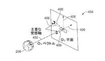
図4の示されている実施例では、衛星100が、惑星208を周回しており、それによって、軌道フレームベクトル402を規定し、それは、O3平面として指定される、対応する軌道フレーム平面404を伴って、シンボルO3によって指定される。この実施例では、ベクトル402が惑星208の重力の中心から、衛星100の重力の中心へ規定される。ベクトル402に基づいて、平面404は、衛星100の重力の中心において規定され、ベクトル402に垂直でもある。図4の実施例では、平面404の座標系の軸406が示されている。この実施例では、衛星100の主要な受感軸408、409が、ベクトル402及び平面404に対して示されている。この実施例では、受感軸408が、衛星100の主要な受感軸である。In the illustrated embodiment of FIG. 4, the
図4の実施例では、衛星100への重力勾配トルクの影響を避ける及び/又は低減させるために、主要な受感軸408及び/又は衛星100の複数の受感軸の内の少なくとも1つが、平面404内に配置される。主要な受感軸及び/又は複数の受感軸のうちの何れかの決定及び/又は規定は、図5に関して以下に詳細に説明されるように、衛星100の方向付け/位置合わせ/姿勢に関する対応する例示的な計算を使用して、決定/規定され得る。しかし、以下に説明される例示的な規定、計算、及び/又は決定は、網羅的なものではない。 In the embodiment of FIG. 4, in order to avoid and / or reduce the effect of gravity gradient torque on the
更に又は代替的に、図4で示される例示的な方向付け/姿勢は、例えば、軌道及び/又は軌道の高度をスイッチするために使用され得る。特に、例えば、軌道を上げる間に衛星100に働く最小の及び/又は実質的にゼロの重力勾配トルクを伴って、衛星100からの推力を提供及び/又は向けることは、有利であり得る。代替的に、受感軸409は、主要な受感軸であり、したがって、重力勾配トルクは、例えば、軌道フレームベクトル402又は軌道フレーム面404の何れかに沿って受感軸409を方向付ける(例えば、位置合わせする)ことによって低減(例えば、最小化)され得る。 Additionally or alternatively, the example orientation / posture shown in FIG. 4 may be used, for example, to switch the trajectory and / or trajectory altitude. In particular, it may be advantageous to provide and / or direct thrust from the
図5は、衛星100に働く重力勾配トルクを低減(例えば、最小化)させるための、図4の例示的な軌道の方向付けに対応する例示的な軸の決定を示す、図1の例示的な衛星100の単純化された描写である。特に、衛星100によって遭遇される重力勾配トルクは、図4に関連して説明された姿勢制御と組み合わされた、衛星100の質量/慣性特性に基づいて、低減及び/又は最小化される。 FIG. 5 illustrates the exemplary axis determination of FIG. 1 corresponding to the exemplary orbit orientation of FIG. 4 to reduce (eg, minimize) the gravity gradient torque acting on the
衛星100によって遭遇された重力勾配トルクを低減させるために、例えば、例示的な衛星100の質量及び/又は慣性特性並びに遭遇された重力勾配トルクは、最初に決定され且つ/又は特徴付けられる。特に、衛星100は、衛星100の重力の中心503からの相対的な距離において、離散した/離散化された質量要素502として特徴付けられる。したがって、衛星100の空間的に依存した慣性特性は、衛星100が展開された状態にあるか又は展開されていない状態にあるか(例えば、太陽電池パネル106が衛星本体102から展開されているか)に基づき得る。特に、本実施例で、i、i+1などによって指定される質量要素502は、重力の中心503から変動する距離にあり、したがって、衛星100の全体の慣性特性を変更し得る。この実施例では、質量要素502の質量/慣性特性が、衛星100の慣性テンソルI、及び/又は質量/慣性行列を規定するために、及び/又は主要な受感及び/又は穏やかな軸を決定するために使用される。この実施例では、慣性テンソルIが、図5で示される方向、x、y、及びzにおいて、衛星100の慣性特性を規定する多変数の配列である。 In order to reduce the gravity gradient torque encountered by the
図5の実施例では、衛星100の慣性特性に基づいて、衛星100に働く重力勾配トルクが、数式1によって計算される。
衛星100の主要な受感軸を計算するために、以下の数式2及び3が、この計算において仮定的に表記される。
ある実施例では、宇宙輸送体の受感軸及び穏やかな軸が、宇宙輸送体の既知の質量/慣性特性に基づいて決定される(例えば、宇宙輸送体の設計に基づいて予め規定される)。例えば、衛星本体102及び太陽電池パネル106の質量特性は、衛星100の設計に基づいて知られ得る。示されている実施例の衛星100が、多数の軸に沿って対称である一方で、衛星の対称でない質量/慣性の分布は、多くの受感軸をもたらし得る。しかし、そのような実施例では、最も多い量の重力勾配トルクを経験することができる1つの受感軸が存在し、したがって、それは指定された主要な受感軸である。図5の例示的な計算が上述の決定のために使用される一方で、これらの実施例は、網羅的なものではなく、任意の適切な計算及び/又は計算方法が使用され得る。図6〜図9で以下に開示される幾つかの他の実施例は、受感軸及び穏やかな軸のこれらの例示的な計算を利用し、推力ベクトル及び/又は動作ベクトルを方向付け、重力勾配トルクを最小化する。 In some embodiments, the space vehicle's sensitive and gentle axes are determined based on known mass / inertia characteristics of the space vehicle (eg, pre-defined based on the space vehicle's design). . For example, the mass characteristics of the
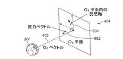
図6は、本開示の教示による、例示的な衛星100の第1の例示的な軌道上昇/下降推力操縦の図1の例示的なベクトル及び平面を示す。図6の実施例では、軌道上昇プロセスの間に、衛星100が、より低い軌道(例えば、軌道202)からより高い軌道(例えば、軌道204)へ移行する。代替的に、衛星100は、より高い軌道からより低い軌道へ移行し得る。 FIG. 6 illustrates the example vectors and planes of FIG. 1 for a first example orbital up / down thrust maneuver of an
図4及び図5との関連で上述された実施例と同様に、軌道フレームベクトル402及び軌道フレーム平面404が示される。しかし、図6の実施例では、衛星100の推力ベクトル602(例えば、結果としての推力ベクトル)が示され、それは、惑星208から離れるような軌道上昇の操縦に対応する。この実施例では、衛星100が、平面404内にある主要な受感軸604を有し、推力ベクトル602は、主要な受感軸604に垂直であり、それによって、本実施例の操縦の間に推力からもたらされる衛星100によって遭遇される重力勾配トルクを低減させる。結果として、重力勾配トルクの低減は、衛星100のスラスタ110及び/又は推進デバイスから必要とされる一定量の操縦を低減させ、それによって、衛星100のより大幅なコンパクト化及び/又は重量の節約を可能にする。 Similar to the embodiment described above in connection with FIGS. 4 and 5, a
この実施例では、衛星100の主要な受感軸604が、図4及び図5との関連で上述された実施例を使用して計算される。特に、主要な受感軸604は、衛星100の慣性特性に基づいて決定される。図5との関連で上述されたように、異なる座標軸の間の慣性値の差異は、衛星100によって経験される非常に大きなトルクをもたらす。 In this example, the primary
図6の例示的な推力の操縦の実行の間に、衛星100によって経験される重力勾配トルクは、主要な受感軸604への推力ベクトル602の垂直な方向付けと組み合わせて、平面404に対する主要な受感軸604の方向付け(例えば、位置合わせ)に基づいて、低減(例えば、最小化)される。代替的に、主要な受感軸604は、ベクトル402に方向付けられ得る。 During the execution of the exemplary thrust maneuver of FIG. 6, the gravity gradient torque experienced by the
示されている実施例の衛星100の推力ベクトル602は、主要な受感軸604に垂直なので、例えば、推力からもたらされる衛星100によって経験されるトルクは、正味の全体的な推力として制御されることができ、最小化される。ある実施例では、主要な受感軸604に対する推力ベクトル602の垂直は、スラスタ110を制御することによって達成され、それによって、スラスタ110からの結果としての推力は、受感軸604に垂直な推力ベクトル602を規定する。言い換えると、推力の方向は、スラスタ110及び/又は多数のスラスタ110からの結果としての推力のうちの少なくとも一方の方向付けによって制御され、それは、必ずしも推力ベクトル602に沿って方向付けられなくともよい。スラスタ110のこの協働的な制御の結果として、推力ベクトル及び/又は結果としての推力ベクトル602を、衛星100の重力の中心に比較的近づけ及び/又は位置合わせすることは、衛星100に伝達されるトルクを低減させ、それによって、例えば、推力の操縦の間に、さもなければ衛星100によって経験されるトルクに対抗するために、必要な装備及び/又はペイロードを低減させる。更に、電子衛星は、しばしば、より高い軌道へ移行する間に展開された太陽電池パネルを必要とし、それは、より大きい特性的な結果としての重力勾配トルクを有する。しかし、本明細書で開示される実施例は、これらの展開された状態の慣性効果と対抗するように使用され得る。 Since the
図6の例示的な方向付け及び/又は推力の操縦は、全体の軌道及び/又は軌道の一部分の間で、軌道を移行する間に実行され得る。例えば、本明細書で説明される姿勢の制御は、惑星208の周りの最終軌道の一部分の間で(例えば、衛星100が、軌道の近地点の近くへ移動する間に)、使用され得る。ある実施例では、例示的な推力の操縦が、例えば、地球を中心とする慣性フレーム(ECI)などの、天体(例えば、惑星、地球、金星など)の慣性フレーム内で実行される。 The exemplary orientation and / or thrust steering of FIG. 6 may be performed during trajectory transitions between the entire trajectory and / or a portion of the trajectory. For example, the attitude control described herein may be used during a portion of the final orbit around the planet 208 (eg, while the
本明細書で開示される実施例が、軌道フレーム平面との主要な受感軸の一般的な方向付けの位置合わせ(例えば、精密な位置合わせ)及び/又は主要な受感軸に対する推力ベクトルの精密な垂直を示す一方で、本明細書で開示される実施例の何れかにおいて、衛星100によって経験される重力勾配トルクを低減させるために、完全な位置合わせは必要でない。そのようにして、重力勾配トルクを低減させるために、主要な受感軸604は、平面404又はベクトル402に対してある程度まで(例えば、5度の範囲内で)位置合わせ/方向付けされることができ、重力勾配トルクを低減させる。同様に、推力ベクトル602は、特定の程度の範囲内で、主要な受感軸604に垂直(例えば、主要な受感軸604の5度の範囲で垂直)でもある。言い換えると、本明細書で開示される実施例に基づく重力勾配トルクの低減の利益は、主要な受感軸604及び推力ベクトル602の精密な方向付け/位置合わせなしでさえ見られ得る。主要な受感軸が軌道フレーム平面/ベクトルに方向付けられる程度、及び/又は推力ベクトルが主要な受感軸に垂直である程度は、衛星の特性(例えば、慣性特性)及び/又は衛星が操縦できる(例えば、衛星についての推力及び/又は推進デバイスの影響の)程度に基づいて変動し得る。 Embodiments disclosed herein may provide a general orientation alignment (eg, precise alignment) of a primary sensitive axis with a trajectory frame plane and / or a thrust vector for the primary sensitive axis. While showing precise verticality, in any of the embodiments disclosed herein, perfect alignment is not necessary to reduce the gravity gradient torque experienced by the
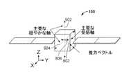
図7は、図6の第1の例示的な軌道上昇/下降推力操縦に関連付けられた例示的な方向軸を示す、図1の例示的な衛星100の単純化された描写である。図7を見ると、穏やかな軸702、704が、衛星100の主要な受感軸604に対して示されている。示されている実施例の穏やかな軸702、704は、衛星100に提供される重力勾配トルクによって大きく影響を受けない軸である。しかし、主要な受感軸604は、図7で示されるx、y、z座標系によって示される、y方向に沿った衛星100の質量分布のために、トルクによって大幅に影響を受け得る。 FIG. 7 is a simplified depiction of the
衛星100に適用されるトルクを最小化するために、推力ベクトル602は、主要な受感軸604に対して垂直に方向付けられるように示されている。図6との関連で上述されたように、推力ベクトル602を衛星100の重力の中心に位置合わせすることは、衛星100の重力の中心に対する推力ベクトル602の距離の分離(例えば、デルタ、位置合わせの分離)を低減(例えば、最小化)することによって、推力のために衛星100に加えられるトルクの量を低減及び/又は最小化させる。 In order to minimize the torque applied to the
図8は、本開示の教示による、第2の例示的な軌道上昇/下降推力操縦の例示的な衛星100の例示的なベクトル及び平面を示している。図6及び図7の実施例とは対照的に、本実施例では、衛星100が惑星208を周回する際に、衛星100は、衛星100の主要な受感軸804に垂直な方向において、推力ベクトル802を生成することができない。衛星100が主要な受感軸804に垂直な推力ベクトルを生成できないことは、スラスタの不具合(例えば、1以上のスラスタが動作しない及び/又は損傷を受けている)、又はスラスタ110からもたらされる正味の推力の方向能力を制限する、スラスタ110の構成及び/又は空間的配置の結果であり得る。 FIG. 8 illustrates exemplary vectors and planes of an
図8の実施例では、衛星100が最初に回転し(例えば、スルーイングされ)、それによって、衛星100の推力ベクトル802が、軌道フレーム平面404に方向付けられる。その後、衛星100は、主要な受感軸804が平面404に方向付けられるまで、推力ベクトル802の周りでスルーイングされる。上述されたように、示されている実施例の推力ベクトル802は、主要な受感軸804に垂直ではない。しかし、衛星100によって経験される重力勾配トルクは、未だ低減及び/又は除去される。 In the example of FIG. 8, the
図9は、図8の第2の例示的な軌道上昇/下降推力操縦に関連付けられた例示的な方向軸を示す、図1の例示的な衛星100の単純化された描写である。図9で見られ得るように、本実施例の衛星100は、推力ベクトル802及び主要な受感軸804に対して、穏やかな軸902及び904を含む。図6及び図7の実施例とは対照的に、推力ベクトル802は、主要な受感軸804に垂直でない。 FIG. 9 is a simplified depiction of the
図9の実施例では、衛星100が推力ベクトル802の周りでスルーイング(例えば、継続的にスルーイング)され、例えば、受信されたセンサデータを介して、平面404の範囲内に推力ベクトル802を維持する。例示的な衛星100は、推力ベクトル802の周りでスルーイング(例えば、継続的にスルーイング)され、主要な受感軸804及び/又は衛星100の受感軸も、平面404の範囲内に維持する。特に、制御アルゴリズムが、使用されて、受信されたセンサデータに基づいて、衛星100の現在の又は予測された位置及び/又は姿勢に基づいて、衛星100をスルーイングし得る。 In the example of FIG. 9, the
上述されたように、本明細書で開示される実施例は、軌道の保守又は軌道の上昇/下降(例えば、軌道の範囲/半径を変えること)の他に、他の用途にも使用され得る。例えば、向けられた通信ベクトルなどの動作ベクトル、太陽電池パネルが向けられたベクトル、ペイロード特徴ベクトル、又はビジュアルセンサベクトルが、推力ベクトルの代わりに軌道フレーム内に向けられ/方向付けられ得る。関連する機能に応じて、これらのベクトルは、主要な受感軸に対して(例えば、垂直に)、及び/又は軌道フレームベクトル/平面に対して(例えば、平行に又は範囲内に)方向付けられ、経験される重力勾配トルクを最小化させ得る。例えば、ペイロード特徴ベクトルが天体に向けて指すようにされ得る一方で、衛星の受感軸は、軌道フレーム平面内に配置され得る。更に又は代替的に、動作ベクトルは、軌道フレーム平面に向けられ/位置合わせされる。 As described above, the embodiments disclosed herein may be used for other applications besides track maintenance or track lift / lower (eg, changing track range / radius). . For example, a motion vector, such as a directed communication vector, a vector directed to a solar panel, a payload feature vector, or a visual sensor vector may be directed / directed into the trajectory frame instead of the thrust vector. Depending on the function involved, these vectors are oriented with respect to the primary sensitive axis (eg, perpendicular) and / or with respect to the trajectory frame vector / plane (eg, parallel or in range). And can minimize the experienced gravity gradient torque. For example, the payload feature vector can be pointed towards the celestial body, while the satellite's sensitive axis can be located in the orbital frame plane. Additionally or alternatively, the motion vector is directed / aligned to the trajectory frame plane.
図10は、本明細書で開示される実施例を実施するために使用され得る、例示的な衛星エネルギー保存システム1000である。示されている実施例の衛星エネルギー保存システム1000は、衛星(例えば、衛星100)内に実装され、衛星ガイダンスシステム1002を有し、それは、推力コントローラ1006、方向付けコントローラ1008、及びセンサインターフェース1010を含む。例示的なエネルギー保存システム1000は、ガイダンスシステム(例えば、衛星ガイダンスシステム)1002、推力コントローラ1006、及び/又はセンサインターフェース1010を、図1で示された衛星スラスタ110と通信可能に接続する通信ライン1016も含む。この実施例では、ガイダンスシステム1002が、アンテナ104とも通信可能に接続され、今度は、アンテナ104が、衛星が周回する惑星208の地上の通信システム1020と通信する。図10の実施例では、ガイダンスシステム1002が、データベース1022に接続され及び/又はそれを含む。 FIG. 10 is an exemplary satellite
動作において、センサインターフェース1010は、例示的な衛星の位置及び/又は姿勢を決定する。特に、センサインターフェース1010は、センサデータ及び/又は惑星208の地上の通信システム1020から受信されたセンサデータに基づいて、衛星の位置、姿勢、及び/又は速度/加速度ベクトルを決定する。 In operation,
この実施例では、衛星が、アンテナ104において地上の通信システム1020から受信した指示命令に基づいて、より高い軌道へ進んでいる。示されている実施例の方向付けコントローラ1008は、衛星から惑星208へ規定されたベクトル(例えば、ベクトル402)に基づいて、軌道のリファレンスフレーム平面(例えば、平面404)を決定する。示されている実施例の方向付けコントローラ1008は、衛星の主要な受感軸を計算する。他の実施例では、方向付けコントローラが、データベース1022から、衛星の質量/慣性データ及び/又は予め規定された受感軸にアクセスする。更に他の実施例では、主要な受感軸が、割り当てられる(地上の通信システム1020から、例えば、受信され、継続的に受信され、アップロードされる)。ある実施例では、示されている実施例の方向付けコントローラ1008が、軌道のリファレンス平面に衛星の主要な受感軸を方向付けるために必要な、衛星の姿勢シフト(例えば、姿勢デルタ)も計算する。更に又は代替的に、例示的な方向付けコントローラ1008は、主要な受感軸が軌道のリファレンスフレーム平面に方向付けられる、衛星の姿勢を計算し、衛星の推力ベクトルが主要な受感軸に垂直となり、衛星に働く重力勾配トルクを低減させる(例えば、最小化させる)一方で、衛星をより高い軌道に移動させる。ある実施例では、方向付けコントローラ1008が、例えば、地上の通信システム1020を介する、手動で制御されるインターフェースである。 In this example, the satellite has advanced to a higher orbit based on an instruction command received at
決定された/計算された姿勢に基づいて、推力コントローラ1006は、衛星の複数のスラスタ110のうちの多くのスラスタを制御し、衛星を、方向付けコントローラ1008から決定された、決定された/計算された姿勢へ移動させる。ある実施例では、推力コントローラ1006が、多数のスラスタの推力パターンを制御し、及び/又は多数のスラスタを動かし、結果としての推力ベクトルを規定して、衛星を決定された姿勢へ調整するために必要な操縦を実行する。更に又は代替的に、推力コントローラ1006は、モーメンタムストレージデバイスなどの推進デバイス及び/又はリアクションホイールを制御して、衛星の姿勢を変更する。 Based on the determined / calculated attitude, the
ある実施例では、衛星の受感軸が、衛星の現在の状態に基づいて計算され、それは、燃料の燃焼及び/又は衛星の展開された状態(例えば、衛星の太陽電池パネルが展開されているか又は展開されていないか)に基づく衛星の充電を含み得る。 In one embodiment, the satellite's sensitivity axis is calculated based on the current state of the satellite, which may be fuel combustion and / or the deployed state of the satellite (eg, whether the satellite's solar panel is deployed). Or charging of the satellite based on whether it has not been deployed.
衛星エネルギー保存システム1000を実装する例示的なやり方が、図10で示されているが、図10で示されている、1以上の要素、プロセス、及び/又はデバイスは、組み合わされ、分割され、再配置され、省略され、及び/又は別の方式で実装されてもよい。更に、図10の例示的な衛星ガイダンスシステム1002、例示的な推力コントローラ1006、例示的な方向付けコントローラ1008、及び/又はより一般的に、例示的な衛星エネルギー保存システム1000は、ハードウェア、ソフトウェア、ファームウェア、並びに/又はハードウェア、ソフトウェア、及び/若しくはファームウェアの任意の組み合わせによって実装され得る。したがって、例えば、例示的な衛星ガイダンスシステム1002、例示的な推力コントローラ1006、例示的な方向付けコントローラ1008、及び/又はより一般的に、例示的な衛星エネルギー保存システム1000のうちの何れかは、1以上のアナログ若しくはデジタル回路、論理回路、プログラマブルプロセッサ、特定用途向け集積回路(ASIC)、プログラマブル論理デバイス(PLD)、及び/又はフィールドプログラマブル論理デバイス(FPLD)によって実装されることができる。本特許出願の装置若しくはシステムクレームのうちの何れかを、純粋にソフトウェア及び/又はファームウェア実装を包含するものとして読む場合、例示的な衛星ガイダンスシステム1002、例示的な推力コントローラ1006、及び/又は例示的な方向付けコントローラ1008のうちの少なくとも1つは、本明細書において、当該ソフトウェア及び/又はファームウェアを記憶するための、メモリ、デジタル多用途ディスク(DVD)、コンパクトディスク(CD)、ブルーレイディスクなどの、有形的コンピュータ可読記憶デバイス若しくは記憶ディスクを含むよう明確に定義される。更に、図10の例示的な衛星エネルギー保存システム1000は、図10に示されるものに加えて又はその代わりに、1以上の要素、プロセス、及び/若しくはデバイスを含み、及び/又は図示される要素、プロセス、及びデバイスのうちの何れか若しくは全てのもののうちの2以上を含み得る。 An exemplary way of implementing the satellite
図10の衛星エネルギー保存システム1000を実装するための例示的な方法を表すフローチャートが、図11〜図13で示されている。これらの実施例で、方法は、図14との関連で以下に説明される例示的なプロセッサプラットフォーム1400内で示されるプロセッサ1412などの、プロセッサによる実行のためのプログラムを含む、機械可読指示命令を使用して実装され得る。プログラムは、CD‐ROM、フロッピーディスク、ハードドライブ、デジタル多用途ディスク(DVD)、ブルーレイディスク、又はプロセッサ1412に関連付けられたメモリなどの、有形的コンピュータ可読記憶媒体に記憶されたソフトウェア内に埋め込まれてもよいが、代替的に、プログラムの全体及び/又は部分がプロセッサ1412以外のデバイスによって実行されてもよく、及び/又はファームウェアもしくは専用のハードウェアに埋め込まれてもよい。更に、例示的なプログラムが、図11〜図13で示されるフローチャートを参照して説明されるが、例示的な衛星エネルギー保存システム1000を実装する他の多くの方法が代替的に使用され得る。例えば、ブロックの実行順は変更され、及び/又は記載されているブロックの幾つかは変更され、排除され、又は組み合わされ得る。 Flow charts representing exemplary methods for implementing the satellite
上述のように、図11〜図13の例示的な方法は、ハードディスクドライブ、フラッシュメモリ、リードオンリーメモリ(ROM)、コンパクトディスク(CD)、デジタル多用途ディスク(DVD)、キャッシュ、ランダムアクセスメモリ(RAM)及び/又は、任意の期間(例えば、長期間、永続的に、短期間、一時的な緩衝用に、及び/又は情報のキャッシング用に)情報が記憶される、任意の他の記憶デバイスもしくは記憶ディスクといった、有形的コンピュータ可読記憶媒体に記憶される符号化された指示命令(例えば、コンピュータ可読指示命令及び/又は機械可読指示命令)を使用して、実装され得る。本明細書で使用されるように、有形的コンピュータ可読記憶媒体という用語は、任意のタイプのコンピュータ可読記憶デバイス及び/又は記憶ディスクを含み、伝播信号を除外し、伝送媒体を除外するように明確に定義される。本明細書で使用される「有形的コンピュータ可読記憶媒体」という用語と「有形的機械可読記憶媒体」という用語は、交換可能に使用される。付加的に又は代替的に、図11〜図13の例示的なプロセスは、ハードディスクドライブ、フラッシュメモリ、リードオンリーメモリ、コンパクトディスク、デジタル多用途ディスク(DVD)、キャッシュ、ランダムアクセスメモリ及び/又は、任意の期間(例えば、長期間、永続的に、短期間、一時的な緩衝用に、及び/又は情報のキャッシング用に)情報が記憶される、任意の他の記憶デバイスもしくは記憶ディスクといった、非一時的なコンピュータ可読媒体及び/又は機械可読媒体に記憶される符号化された指令(例えば、コンピュータ可読指令及び/又は機械可読指令)を使用して、実装され得る。本明細書で使用する、非一過性コンピュータ可読媒体という用語は、任意のタイプのコンピュータ可読記憶デバイス及び/又は記憶ディスクを含み、伝播信号を除外し、伝送媒体を除外するように明確に定義される。本明細書で使用されるフレーズ「少なくとも」は、請求項の前文における移行用語として使用され、用語「含む」がオープンエンドであるのと同じ方式でオープンエンドである。 As described above, the exemplary methods of FIGS. 11-13 include hard disk drives, flash memory, read only memory (ROM), compact disk (CD), digital versatile disk (DVD), cache, random access memory ( RAM) and / or any other storage device in which information is stored for any period of time (eg, long term, permanently, short term, for temporary buffering, and / or for caching information) Alternatively, it may be implemented using encoded instruction instructions (eg, computer readable instruction instructions and / or machine readable instruction instructions) stored on a tangible computer readable storage medium, such as a storage disk. As used herein, the term tangible computer readable storage medium includes any type of computer readable storage device and / or storage disk and is specifically defined to exclude propagating signals and exclude transmission media. Defined in As used herein, the terms “tangible computer readable storage medium” and “tangible machine readable storage medium” are used interchangeably. Additionally or alternatively, the exemplary processes of FIGS. 11-13 include a hard disk drive, flash memory, read only memory, compact disk, digital versatile disk (DVD), cache, random access memory, and / or Any non-storage device or storage disk where information is stored for any period (eg, long-term, permanently, short-term, for temporary buffering, and / or for caching information) It may be implemented using encoded instructions (eg, computer readable instructions and / or machine readable instructions) stored on transitory computer readable media and / or machine readable media. As used herein, the term non-transitory computer readable medium includes any type of computer readable storage device and / or storage disk and is clearly defined to exclude propagating signals and exclude transmission media. Is done. As used herein, the phrase “at least” is used as a transition term in the preamble of the claim and is open-ended in the same manner that the term “includes” is open-ended.
図11の例示的な方法は、ブロック1100で始まり、衛星100などの衛星が、操縦及び/又は方向付けされて、天体(例えば、惑星208)から衛星に働く重力勾配トルクを低減させる(ブロック1100)。特に、衛星は、軌道(例えば、最終軌道)内で天体を周回しており、より高い軌道において機能(例えば、通信、情報収集など)を実行するために、より高い軌道へ入らんとし得る。 The example method of FIG. 11 begins at
図11の実施例では、衛星の位置及び方向/姿勢が決定される(ブロック1102)。例えば、センサインターフェース1010などのセンサインターフェースが、センサデータを集め及び/又は収集し、天体に対する衛星の相対的な位置及び姿勢を決定する。ある実施例では、衛星の予測される速度及び/又は姿勢が、現在の衛星の移動状態及び/又は天体に対する衛星の相対的な位置に基づいて、決定される(例えば、時間の関数として予測される)。 In the example of FIG. 11, the position and orientation / attitude of the satellite is determined (block 1102). For example, a sensor interface, such as
有る実施例では、衛星の受感軸が計算される(ブロック1104)。特に、衛星の質量/慣性データが使用されて、受感軸を決定し得る。他の実施例では、主要な受感軸が、衛星の設計に基づいて、予め規定され及び/又は知られている。更に又は代替的に、受感軸は、衛星の現在の状態(例えば、燃料の燃焼、衛星の更新された状態など)に対応する、更新された質量/慣性特性に基づいて計算される。 In one embodiment, the satellite sensitivity axis is calculated (block 1104). In particular, satellite mass / inertia data may be used to determine the sensitive axis. In other embodiments, the primary sensitive axis is predefined and / or known based on the satellite design. Additionally or alternatively, the sensitivity axis is calculated based on updated mass / inertia characteristics corresponding to the current state of the satellite (eg, fuel combustion, updated state of the satellite, etc.).
次に、示されている実施例の衛星は、受感軸が、決定された軌道フレーム平面(例えば、平面404)に方向付けられるように、操縦され且つ/又は方向付けられる(ブロック1106)。代替的に、受感軸は、軌道フレームベクトル(例えば、ベクトル402)に方向付けられる。 Next, the satellite of the illustrated embodiment is steered and / or oriented (block 1106) such that the sensitive axis is directed to the determined orbit frame plane (eg, plane 404). Alternatively, the sensitive axis is directed to a trajectory frame vector (eg, vector 402).
衛星が異なる軌道へ移動(例えば、軌道上昇)されている、ある実施例では、衛星の推力ベクトル(例えば、推力ベクトル602)が、主要な受感軸と垂直に方向付けられる(ブロック1107)。ある実施例では、推力ベクトルが、(例えば、同じ操縦の間に)軌道フレーム平面に方向付けられている衛星の受感軸と同時に、主要な受感軸と垂直に方向付けられる。 In one embodiment where the satellite is moved to a different orbit (eg, orbital uplift), the satellite's thrust vector (eg, thrust vector 602) is oriented perpendicular to the primary sensitive axis (block 1107). In one embodiment, the thrust vector is oriented perpendicular to the primary perception axis simultaneously with the satellite perception axis that is directed to the orbital frame plane (eg, during the same maneuver).
衛星が異なる軌道へ移動される実施例では、一旦、衛星が方向付けられると、衛星のスラスタ又は他の移動デバイスが、操作/起動され、衛星の軌道の高度を変更する(ブロック1108)。ある実施例では、このスラスタが、衛星が方向付けられ(ブロック1106及び/又は1107)る際に、軌道を上げる操縦に対して同時に操作され、その後、プロセスは終了する(ブロック1110)。代替的に、主要な受感軸に垂直な、結果としての推力ベクトルに対して多くのスラスタが起動される。 In embodiments where the satellites are moved to different orbits, once the satellites are oriented, the satellite thrusters or other moving devices are operated / activated to change the altitude of the satellite's orbit (block 1108). In one embodiment, this thruster is operated simultaneously for maneuvers that raise orbits as the satellite is directed (
図12は、本明細書で開示される実施例を実施する別の例示的な方法のフローチャートである。図12の例示的な方法では、天体を周回している衛星が、軌道上昇を経験しているが、限られた推力の操縦能力及び/又は限られたスラスタの方向付けを有している。図12の例示的な方法は、ブロック1200で始まり、衛星は、軌道上昇の操縦を開始している(ブロック1200)。 FIG. 12 is a flowchart of another exemplary method for practicing the embodiments disclosed herein. In the exemplary method of FIG. 12, a satellite orbiting a celestial body is experiencing orbital rise but has limited thrust maneuverability and / or limited thruster orientation. The example method of FIG. 12 begins at
衛星の第1の位置及び第1の方向/姿勢が、決定される(ブロック1202)。次に、衛星は、操縦及び/又は方向付けされ(例えば、スルーイングされ)、それによって、衛星の推力ベクトルが、決定された軌道フレーム平面(例えば、平面404)内ある(ブロック1204)。例えば、軌道フレーム平面は、例示的な衛星の方向付けコントローラ(例えば、方向付けコントローラ1008)によって、時間の関数として決定され得る。この実施例では、示されている実施例の軌道フレーム平面が、時を経て変化する衛星の位置の関数として決定される。 A first position and a first direction / attitude of the satellite are determined (block 1202). The satellite is then steered and / or directed (eg, slewed) so that the thrust vector of the satellite is within the determined orbit frame plane (eg, plane 404) (block 1204). For example, the orbital frame plane may be determined as a function of time by an exemplary satellite orientation controller (eg, orientation controller 1008). In this embodiment, the orbit frame plane of the illustrated embodiment is determined as a function of satellite position, which changes over time.
図12の実施例では、衛星が、推力ベクトルの周りでスルーイングされ(例えば、推力ベクトルの周りで回転され)、それによって、衛星の受感軸が、決定された軌道フレーム平面に方向付けられる(ブロック1206)。 In the embodiment of FIG. 12, the satellite is slewed around the thrust vector (eg, rotated around the thrust vector), thereby directing the satellite's sensitive axis to the determined orbit frame plane. (Block 1206).
衛星が操縦された後で、センサインターフェース1010などのセンサインターフェースを介して、衛星の第2の位置及び第2の方向が決定される(ブロック1208)。ある実施例では、天体の地上のシステムが、例えば、地上の通信システム1020などの通信システムを介して、衛星の位置及び方向を決定する。 After the satellite is maneuvered, the second position and second direction of the satellite are determined via a sensor interface, such as sensor interface 1010 (block 1208). In one embodiment, a celestial terrestrial system determines the position and orientation of a satellite via a communication system, such as a
次に、衛星の更なる調整が必要か否かが決定される(ブロック1210)。ある実施例では、この決定が、(例えば、軌道の一部分の間で)衛星の継続的な姿勢の調整が必要か否か、及び/又は衛星が計画された軌跡からずれているか否かを分析することによって行われる。 Next, it is determined whether further adjustment of the satellite is necessary (block 1210). In some embodiments, this determination analyzes whether a continuous attitude adjustment of the satellite is required (eg, during a portion of the orbit) and / or whether the satellite is off the planned trajectory. Is done by doing.
衛星の更なる調整が必要であると決定されたならば(ブロック1210)、プロセスは、制御をブロック1202に戻す。衛星の更なる調整が必要でないと決定されたならば(ブロック1210)、例示的なプロセスは終了する(ブロック1212)。 If it is determined that further satellite adjustment is required (block 1210), the process returns control to block 1202. If it is determined that no further satellite adjustment is required (block 1210), the example process ends (block 1212).
図13は、本明細書で開示される実施例を実施する更に別の例示的な方法のフローチャートである。例示的な方法は、ブロック1300で始まり、天体を周回している例示的な衛星は、最終軌道内にある(ブロック1300)。しかし、衛星は、軌道の部分の間で操縦されており、衛星が受ける重力勾配トルクを最小化及び/又は低減させる。 FIG. 13 is a flowchart of yet another exemplary method for implementing the embodiments disclosed herein. The exemplary method begins at
図13の実施例では、衛星の第1の姿勢が決定される(ブロック1302)。この決定は、センサインターフェース(例えば、センサインターフェース1010)のセンサを用いる通信、及び/又は地上の通信(例えば、通信システム1020)を介して行われ得る。 In the example of FIG. 13, a first attitude of the satellite is determined (block 1302). This determination may be made via communication using sensors of a sensor interface (eg, sensor interface 1010) and / or via ground communication (eg, communication system 1020).
次に、衛星の受感軸(例えば、主要な受感軸)が、決定される(ブロック1303)。ある実施例では、受感軸が、現在の衛星の状態(例えば、展開された位置、燃料の燃焼など)に基づいて計算される。 Next, the perception axis (eg, primary perception axis) of the satellite is determined (block 1303). In some embodiments, the sensitive axis is calculated based on the current satellite conditions (eg, deployed position, fuel combustion, etc.).
図13の実施例では、軌道フレーム平面が、軌道フレーム変換行列に基づいて計算される(ブロック1304)。例えば、軌道フレーム平面は、衛星の重力の中心から衛星が周回している天体の重力の中心へ向けられた軌道に基づき得る。 In the example of FIG. 13, a trajectory frame plane is calculated based on the trajectory frame transformation matrix (block 1304). For example, the orbit frame plane may be based on a trajectory directed from the center of gravity of the satellite to the center of gravity of the celestial body around which the satellite is orbiting.
図13の実施例では、衛星の第2の姿勢が決定/計算され、衛星の受感軸を軌道フレーム平面(例えば、平面404)に方向付ける(ブロック1306)。例えば、方向付けコントローラ1008などの方向付けコントローラは、衛星に対する姿勢の変化(例えば、デルタ)を計算し得る。ある実施例では、計算された姿勢の変化が、時間の関数として計算され得る。 In the example of FIG. 13, a second attitude of the satellite is determined / calculated to orient the satellite's sensitive axis to the orbital frame plane (eg, plane 404) (block 1306). For example, a direction controller, such as
衛星の第2の高度に基づいて、衛星のスラスタ及び/又は推進デバイス(例えば、リアクションホイール)が、推力コントローラ1006などの推力コントローラによって制御され、衛星を第2の姿勢へ移動させる(ブロック1307)。 Based on the satellite's second altitude, a satellite thruster and / or propulsion device (eg, a reaction wheel) is controlled by a thrust controller, such as
次に、衛星の更なる姿勢の調整が必要か否かが決定される(ブロック1308)。衛星の姿勢の更なる調整が必要ならば(ブロック1308)、プロセスの制御はブロック1302へ戻る。代替的に、更なる調整が必要でなければ(ブロック1308)、プロセスは終了する(ブロック1310)。 Next, it is determined whether further satellite attitude adjustment is required (block 1308). If further adjustment of the satellite attitude is required (block 1308), control of the process returns to block 1302. Alternatively, if no further adjustment is required (block 1308), the process ends (block 1310).
図14は、図10の例示的な衛星エネルギー保存システム1000を実装する、図11〜図13の例示的な方法を実行することができる、例示的なプロセッサプラットフォーム1400のブロック図である。プロセッサプラットフォーム1400は、例えば、サーバ、パーソナルコンピュータ、モバイルデバイス(例えば、パーソナルデジタルアシスタント(PDA))、インターネット家電、又は任意の他のタイプのコンピューティングデバイスであり得る。 14 is a block diagram of an
示されている実施例のプロセッサプラットフォーム1400は、プロセッサ1412を含む。示されている実施例のプロセッサ1412は、ハードウェアである。例えば、プロセッサ1412は、任意の望ましいファミリーもしくは製造者からの、1以上の集積回路、論理回路、マイクロプロセッサ、又はコントローラによって実装されることができる。 The illustrated
示されている実施例のプロセッサ1412は、ローカルメモリ1412(例えば、キャッシュ)を含む。例示的なプロセッサ1412は、推力コントローラ1005、方向付けコントローラ1008、及びセンサインターフェース1010も含む。示されている実施例のプロセッサ1412は、揮発性メモリ1414及び不揮発性メモリ1416を含むメインメモリと、バス1418を介して通信可能である。揮発性メモリ1414は、同期型ダイナミックランダムアクセスメモリ(SDRAM)、ダイナミックランダムアクセスメモリ(DRAM)、RAMBUSダイナミックランダムアクセスメモリ(RDRAM)、及び/又は任意の他のタイプのランダムアクセスメモリデバイスによって実装され得る。不揮発性メモリ1416は、フラッシュメモリ及び/又は任意の他の望ましいタイプのメモリデバイスによって実装され得る。メインメモリ1414、1416へのアクセスは、メモリコントローラによって制御される。 The
示されている実施例のプロセッサプラットフォーム1400は、インターフェース回路1420も含む。インターフェース回路1420は、イーサネットインターフェース、ユニバーサルシリアルバス(USB)、及び/又はPCIエクスプレスインターフェースといった任意のタイプのインターフェース規格で実装され得る。 The
示されている実施例では、1以上の入力デバイス1422がインターフェース回路1420に接続される。入力デバイス1422は、ユーザがデータ及びコマンドをプロセッサ1412に入力することを可能にする。入力デバイスは、例えば、音声センサ、マイクロフォン、カメラ(静止画又はビデオ)、キーボード、ボタン、マウス、タッチスクリーン、トラックパッド、トラックボール、アイソポイント(isopoint)、及び/又は音声認識システムによって実装されることができる。 In the illustrated embodiment, one or
1以上の出力デバイス1424も、示されている実施例のインターフェース回路1420に接続される。出力デバイス1424は、例えば、ディスプレイデバイス(例えば、発光ダイオード(LED)、有機発光ダイオード(OLED)、液晶ディスプレイ、カソードレイチューブディスプレイ(CRT)、タッチスクリーン、触覚出力デバイス、プリンタ及び/又はスピーカ)によって、実装されることができる。したがって、図示した例のインターフェース回路1420は、典型的にはグラフィックドライバカード、グラフィックドライバチップ又はグラフィックドライバプロセッサを含む。 One or
例示の実施例のインターフェース回路1420は、外部の機械(例えば、任意の種類のコンピューティングデバイス)との、ネットワーク1426(例えば、イーサネット接続、デジタル加入者線(DSL)、電話線、同軸ケーブル、セルラフォンシステムなど)を介したデータ授受を容易にするための、送信機、受信機、トランシーバ、モデム、及び/又はネットワークインターフェースカードなどの通信デバイスも含む。 The
示されている実施例のプロセッサプラットフォーム1400は、ソフトウェア及び/又はデータを記憶するための1以上の大容量記憶デバイス1428も含む。そのような大容量記憶デバイス1428は、フロッピーディスク、ハードドライブディスク、コンパクトディスク、ブルーレイディスク、RAIDシステム、及びデジタル多用途ディスク(DVD)ドライブを含む。 The
図11〜図13に記載の方法を実装するための符号化された指示命令1432は、大容量記憶デバイス1428、揮発性メモリ1414、不揮発性メモリ1416、及び/又はCD若しくはDVDといった取り外し可能な有形的コンピュータ可読記憶媒体に、記憶され得る。 The encoded
以上のことから、上述の方法及び装置は、衛星/RSOのエネルギー効率に優れた動作を可能にし、それによって、よりコンパクトで重量を節約した衛星/RSOを可能にする。高められたコンパクト化及び重量の節約は、対応する宇宙打上げ機に対する低減されたペイロード要求をもたらす。 In view of the foregoing, the above-described methods and apparatus enable satellite / RSO energy efficient operation, thereby enabling a more compact and weight-saving satellite / RSO. Increased compactness and weight savings result in reduced payload requirements for corresponding space launchers.
特定の例示的な方法及び装置が本明細書で開示されたが、本特許出願の範囲はこれらに限定されるものではない。反対に、本特許出願は、本特許出願の特許請求の範囲内に公正に当てはまる全ての方法、装置、及び製品を包含する。衛星が開示されたが、例示的な方法は及び装置は、車両、空力構造などに適用され得る。
Although certain exemplary methods and apparatus have been disclosed herein, the scope of this patent application is not limited thereto. On the contrary, this patent application includes all methods, devices, and products that fall within the scope of the claims of this patent application. Although a satellite has been disclosed, the exemplary methods and apparatus can be applied to vehicles, aerodynamic structures, and the like.
Claims (12)
Translated fromJapanese前記操縦デバイスが、前記衛星の主要な受感軸を軌道フレーム平面に方向付けて、前記衛星に働く重力勾配トルクを低減させることをもたらす、方向付けコントローラを備える、装置。An apparatus comprising: a satellite steering device; and the steering device directing a primary sensitive axis of the satellite to an orbital frame plane to reduce gravity gradient torque acting on the satellite.
12. An apparatus according to any one of claims 7 to 11 wherein the steering device comprises a momentum storage device.
Applications Claiming Priority (2)
| Application Number | Priority Date | Filing Date | Title |
|---|---|---|---|
| US14/940,811US10005568B2 (en) | 2015-11-13 | 2015-11-13 | Energy efficient satellite maneuvering |
| US14/940,811 | 2015-11-13 |
Publications (2)
| Publication Number | Publication Date |
|---|---|
| JP2017137040Atrue JP2017137040A (en) | 2017-08-10 |
| JP6989252B2 JP6989252B2 (en) | 2022-01-05 |
Family
ID=56799310
Family Applications (1)
| Application Number | Title | Priority Date | Filing Date |
|---|---|---|---|
| JP2016217175AActiveJP6989252B2 (en) | 2015-11-13 | 2016-11-07 | Energy-efficient satellite maneuvering |
Country Status (7)
| Country | Link |
|---|---|
| US (4) | US10005568B2 (en) |
| EP (1) | EP3170753B1 (en) |
| JP (1) | JP6989252B2 (en) |
| KR (1) | KR102644042B1 (en) |
| CN (1) | CN106697331B (en) |
| CA (1) | CA2941062C (en) |
| RU (1) | RU2737644C2 (en) |
Cited By (1)
| Publication number | Priority date | Publication date | Assignee | Title |
|---|---|---|---|---|
| WO2021171409A1 (en)* | 2020-02-26 | 2021-09-02 | 三菱電機株式会社 | Orbital attitude control device, satellite, orbital attitude control method, and program |
Families Citing this family (12)
| Publication number | Priority date | Publication date | Assignee | Title |
|---|---|---|---|---|
| US10005568B2 (en)* | 2015-11-13 | 2018-06-26 | The Boeing Company | Energy efficient satellite maneuvering |
| FR3047813B1 (en)* | 2016-02-16 | 2019-11-08 | Airbus Defence And Space Sas | METHOD FOR CONTROLLING SATELLITE ATTITUDE GUIDANCE, SATELLITE, SATELLITE PLURALITIES AND ASSOCIATED COMPUTER PROGRAM |
| US10569909B2 (en) | 2016-03-30 | 2020-02-25 | The Boeing Company | Systems and methods for satellite orbit and momentum control |
| US10543939B2 (en)* | 2018-02-09 | 2020-01-28 | Launchspace Technologies Corporation | Apparatus and methods for creating artificial near-earth orbits |
| US11091280B1 (en)* | 2018-06-05 | 2021-08-17 | United States Of America As Represented By The Administrator Of Nasa | Modelling and analyzing inter-satellite relative motion |
| US11279501B2 (en)* | 2018-10-25 | 2022-03-22 | General Atomics | Satellite attitude control system using eigen vector, non-linear dynamic inversion, and feedforward control |
| CN109649689B (en)* | 2018-12-07 | 2021-10-01 | 北京空间飞行器总体设计部 | Method for calculating gravity loss of orbital change with limited thrust and thrust calculation device |
| KR20230155576A (en)* | 2021-03-16 | 2023-11-10 | 에이에스티 앤 사이언스, 엘엘씨 | Momentum wheels and recoil wheels for objects in space |
| CN113212804B (en)* | 2021-04-30 | 2022-07-29 | 北京控制工程研究所 | An integrated control method for attitude and angular momentum of a tethered satellite |
| US20230148291A1 (en)* | 2021-11-05 | 2023-05-11 | Harold Ariel Tavarez | Propellantless propulsion system and method |
| US20240094408A1 (en)* | 2022-09-19 | 2024-03-21 | Kymeta Corporation | Satellite (re-)acquisition and state estimation for mobile flat-panel satellite terminals |
| CN119294160B (en)* | 2024-12-16 | 2025-03-21 | 北京控制工程研究所 | A method for modeling complex connected multi-body dynamics with large inertia rotating loads |
Citations (6)
| Publication number | Priority date | Publication date | Assignee | Title |
|---|---|---|---|---|
| JP2002037200A (en)* | 2000-07-28 | 2002-02-06 | Mitsubishi Electric Corp | Satellite with orbit inclination |
| JP2004210032A (en)* | 2002-12-27 | 2004-07-29 | Mitsubishi Electric Corp | Formation flight satellite |
| US20080128559A1 (en)* | 2006-12-04 | 2008-06-05 | The Boeing Company | Optimal sun safe attitude for satellite ground tracking |
| JP2010533290A (en)* | 2007-07-10 | 2010-10-21 | アストリウム エスアーエス | Ground user positioning system |
| CN104038272A (en)* | 2014-06-10 | 2014-09-10 | 哈尔滨工业大学 | Medium earth orbit (MEO) global coverage constellation under limit of illumination |
| WO2015130950A2 (en)* | 2014-02-26 | 2015-09-03 | Clark Emerson Cohen | An improved performance and cost global navigation satellite system architecture |
Family Cites Families (114)
| Publication number | Priority date | Publication date | Assignee | Title |
|---|---|---|---|---|
| FR88335E (en)* | 1958-09-04 | 1967-01-20 | Device for rotating the plane of the orbit of a moving object in gravity as well as moving objects such as satellites, provided with the present device or similar device | |
| US3068218A (en) | 1961-02-20 | 1962-12-11 | Standard Oil Co | Sulfochlorination of hydrocarbons |
| US3558078A (en)* | 1967-08-21 | 1971-01-26 | Whittaker Corp | Space vehicle attitude control |
| US3767139A (en)* | 1971-06-21 | 1973-10-23 | Us Navy | Spacecraft spin stabilization system |
| US3866025A (en)* | 1972-03-17 | 1975-02-11 | Rca Corp | Spacecraft attitude control system |
| DE2642061C2 (en)* | 1976-09-18 | 1983-11-24 | Messerschmitt-Bölkow-Blohm GmbH, 8000 München | Position control and orbit change method for a three-axis stabilizable satellite, in particular for a geostationary satellite and device for carrying out the method |
| US4071211A (en)* | 1976-09-23 | 1978-01-31 | Rca Corporation | Momentum biased active three-axis satellite attitude control system |
| US4294420A (en)* | 1978-01-30 | 1981-10-13 | Matra | Attitude control systems for space vehicles |
| US4230296A (en)* | 1979-02-21 | 1980-10-28 | Staley Gary M | Holding device for hunting equipment |
| US4306692A (en)* | 1979-03-16 | 1981-12-22 | Communications Satellite Corporation | Attitude acquisition maneuver for a bias momentum spacecraft |
| US4230294A (en)* | 1979-07-23 | 1980-10-28 | Rca Corporation | Closed loop roll control for momentum biased satellites |
| DE3071249D1 (en)* | 1980-08-19 | 1986-01-02 | Messerschmitt Boelkow Blohm | Attitude control device for elastic vehicles |
| US4617634A (en)* | 1983-06-28 | 1986-10-14 | Mitsubishi Denki Kabushiki Kaisha | Artificial satellite attitude control system |
| US4728061A (en)* | 1985-03-20 | 1988-03-01 | Space Industries, Inc. | Spacecraft operable in two alternative flight modes |
| US4757964A (en)* | 1986-07-17 | 1988-07-19 | Hughes Aircraft Company | Method for controlling the attitude of a spinning body in orbit |
| US4767084A (en)* | 1986-09-18 | 1988-08-30 | Ford Aerospace & Communications Corporation | Autonomous stationkeeping for three-axis stabilized spacecraft |
| WO1990001447A1 (en)* | 1988-08-12 | 1990-02-22 | Nippon Telegraph And Telephone Corporation | Method and apparatus for changing orbit of artificial satellite |
| FR2647565B1 (en)* | 1989-04-24 | 1991-07-26 | Alcatel Espace | METHOD FOR POSTING A GEOSTATIONARY TELECOMMUNICATIONS SATELLITE |
| FR2655167B1 (en)* | 1989-11-29 | 1992-04-03 | Aerospatiale | METHOD OF CONTROLLING ATTITUDE IN ROLL AND LACET OF A SATELLITE. |
| US5123617A (en)* | 1990-03-05 | 1992-06-23 | General Electric Company | Spacecraft momentum unloading using controlled magnetic torques |
| FR2669887B1 (en)* | 1990-11-30 | 1995-06-02 | Aerospatiale | METHOD FOR CONTROLLING THE ATTITUDE IN TANGAGE OF A SATELLITE THANKS TO THE SOLAR RADIATION PRESSURE AND SATELLITE SUITABLE FOR ITS IMPLEMENTATION. |
| FR2670746B1 (en)* | 1990-12-21 | 1993-04-16 | Aerospatiale | ATTITUDE MONITORING SYSTEM FOR 3-AXIS SATELLITE ,; IN PARTICULAR FOR OBSERVATION SATELLITE. |
| DE4114804A1 (en)* | 1991-05-07 | 1992-11-12 | Messerschmitt Boelkow Blohm | DEVICE FOR THE POSITION CONTROL OF SATELLITES WITH SOLAR PRESSURE MOMENTS |
| US5377936A (en)* | 1992-03-19 | 1995-01-03 | Mitchell; Maurice | Net kinetic energy differential guidance and propulsion system for satellites and space vehicles |
| US5248118A (en)* | 1992-05-13 | 1993-09-28 | General Electric Co. | Spacecraft attitude control system with reaction wheel bearing protection |
| US5310144A (en) | 1992-07-06 | 1994-05-10 | Hughes Aircraft Company | Method and apparatus for satellite torque balancing |
| US5354016A (en)* | 1992-07-30 | 1994-10-11 | General Electric Co. | Pivoted wheel roll control with automatic offset |
| US5452869A (en)* | 1992-12-18 | 1995-09-26 | Hughes Aircraft Company | On-board three-axes attitude determination and control system |
| US5443231A (en)* | 1993-11-17 | 1995-08-22 | Hughes Aircraft Company | Method and apparatus for a satellite station keeping |
| US5400033A (en)* | 1994-02-07 | 1995-03-21 | Rockwell International Corporation | Tracking system for tracking targets with a spacecraft |
| US5459669A (en)* | 1994-02-14 | 1995-10-17 | Space Systems/Loral, Inc. | Control system and method for spacecraft attitude control |
| US5595360A (en)* | 1994-03-25 | 1997-01-21 | Hughes Aircraft Company | Optimal transfer orbit trajectory using electric propulsion |
| US5669586A (en) | 1994-12-06 | 1997-09-23 | Space Systems/Loral, Inc. | Satellite gravity gradient compensation using on-orbit solar array reorientation |
| US5610820A (en)* | 1995-03-23 | 1997-03-11 | Martin Marietta Corp. | Minimum propellant, zero momentum spacecraft attitude control system |
| DE19520410A1 (en)* | 1995-06-09 | 1996-12-12 | Daimler Benz Aerospace Ag | Earth-oriented satellite and method for position, nutation and wheel spin control |
| US5646847A (en)* | 1995-08-25 | 1997-07-08 | Martin Marietta Corp. | Universal thruster selection logic for spacecraft attitude control |
| US6102337A (en)* | 1995-12-22 | 2000-08-15 | Hughes Electronics Corporation | Spacecraft attitude control with gimbaled thrusters |
| US5984236A (en)* | 1995-12-22 | 1999-11-16 | Keitel; Keith F. | Momentum unloading using gimbaled thrusters |
| US5791598A (en)* | 1996-01-16 | 1998-08-11 | Globalstar L.P. and Daimler-Benz Aerospace AG | Dynamic bias for orbital yaw steering |
| US5826828A (en) | 1996-02-05 | 1998-10-27 | Hughes Electronics Corporation | Sun/earth acquisition without thrusters |
| US5934620A (en)* | 1996-03-04 | 1999-08-10 | Abernethy; David K. | Spacecraft sun-target steering about an arbitrary body axis |
| FR2748721A1 (en)* | 1996-05-17 | 1997-11-21 | Matra Marconi Space France | APPARATUS FOR ADJUSTING THE ROTATION OF A SPATIAL VESSEL AROUND A AXIS |
| US5826829A (en)* | 1996-07-15 | 1998-10-27 | Space Systems/Loral Inc. | Spacecraft control system with a trihedral momentum bias wheel configuration |
| US6053455A (en)* | 1997-01-27 | 2000-04-25 | Space Systems/Loral, Inc. | Spacecraft attitude control system using low thrust thrusters |
| US6068218A (en)* | 1997-05-14 | 2000-05-30 | Hughes Electronics Corporation | Agile, spinning spacecraft with sun-steerable solar cell array and method |
| US5947421A (en)* | 1997-07-09 | 1999-09-07 | Beattie; John R. | Electrostatic propulsion systems and methods |
| US6125310A (en)* | 1997-07-18 | 2000-09-26 | Space Systems/Loral, Inc. | Thruster on time signaling with flexure compensation avoidance |
| US6062512A (en)* | 1997-08-27 | 2000-05-16 | Hughes Electronics Corporation | Wobble and nutation control, and spin stabilization for a spacecraft using momentum conserving devices |
| US6032903A (en)* | 1998-02-12 | 2000-03-07 | Hughes Electronics Corporation | Cooperative control structures and methods for satellite spin axis control |
| US6032904A (en)* | 1998-02-23 | 2000-03-07 | Space Systems/Loral, Inc. | Multiple usage thruster mounting configuration |
| US6070833A (en)* | 1998-04-09 | 2000-06-06 | Hughes Electronics Corporation | Methods for reducing solar array power variations while managing the system influences of operating with off-pointed solar wings |
| US6293502B1 (en)* | 1998-08-05 | 2001-09-25 | Hughes Electronics Corporation | System and method for enhanced solar array pointing in sun-nadir steering |
| US6020956A (en)* | 1999-02-04 | 2000-02-01 | The Aerospace Corporation | Pseudo gyro |
| DE19924908B4 (en)* | 1999-05-31 | 2008-05-29 | Astrium Gmbh | Three-axis attitude determination method for a low-flying satellite |
| US7113851B1 (en)* | 1999-06-09 | 2006-09-26 | Walter Gelon | Practical orbit raising system and method for geosynchronous satellites |
| US6253125B1 (en)* | 2000-03-01 | 2001-06-26 | Space Systems/Loral, Inc. | Method and apparatus for generating orbital data |
| US6263264B1 (en)* | 2000-06-08 | 2001-07-17 | The Aerospace Corporation | Pseudo gyro with unmodeled disturbance torque estimation |
| US6237876B1 (en)* | 2000-07-28 | 2001-05-29 | Space Systems/Loral, Inc. | Methods for using satellite state vector prediction to provide three-axis satellite attitude control |
| US6481672B1 (en)* | 2001-01-18 | 2002-11-19 | Lockheed Martin Corporation | Gimbaled thruster control system |
| US6435457B1 (en)* | 2001-01-25 | 2002-08-20 | The Boeing Company | Thruster systems for spacecraft station changing, station keeping and momentum dumping |
| US6745984B2 (en)* | 2002-04-23 | 2004-06-08 | Astrium Sas | Method of controlling the attitude and stabilization of a satellite in low orbit |
| US20040050191A1 (en)* | 2002-07-10 | 2004-03-18 | Byung-Tae Chung | Internal propulsion apparatus of closed system utilizing Coriolis force |
| US20050005719A1 (en)* | 2003-06-16 | 2005-01-13 | Byung-Tae Chung | Method for generating a non-inertial coriolis force and its application to an internal propulsion device in a closed system |
| US7464898B1 (en)* | 2003-10-14 | 2008-12-16 | Lockheed Martin Corporation | Precision thrust/sun tracking attitude control system for gimbaled thruster |
| US7654490B2 (en)* | 2003-10-14 | 2010-02-02 | Lockheed Martin Corporation | Precision attitude control system for gimbaled thruster |
| FR2861690B1 (en)* | 2003-11-04 | 2006-04-07 | Eads Astrium Sas | ATTITUDE CONTROL OF SATELLITES IN PARTICULAR AGILES WITH REDUCED NUMBER OF GYRODYNES |
| US6860451B1 (en)* | 2003-11-21 | 2005-03-01 | The Boeing Company | Spacecraft spin axis reorientation method |
| US20050247145A1 (en)* | 2004-05-04 | 2005-11-10 | Legoff Yves | Three-dimension motive machine |
| US7464899B2 (en)* | 2005-08-03 | 2008-12-16 | Honeywell International Inc. | Method and system for determining a singularity free momentum path |
| US7376496B1 (en)* | 2005-12-13 | 2008-05-20 | Lockheed Martin Corporation | Spacecraft magnetic momentum control system |
| CN100451898C (en)* | 2005-12-14 | 2009-01-14 | 上海微小卫星工程中心 | Method and system for controlling mini-satellite position by active magnetic force |
| IL175596A0 (en)* | 2006-05-11 | 2007-07-04 | Rafael Advanced Defense Sys | Low orbit missile-shaped satellite for electro-optical earth surveillance and other missions |
| RU2309876C1 (en)* | 2006-05-23 | 2007-11-10 | Федеральное государственное научное учреждение "Государственный научно-исследовательский институт прикладной механики и электродинамики" (ФГНУ "НИИ ПМЭ") | Method of control of spacecraft motion and control system for realization of this method |
| US20090108136A1 (en)* | 2006-06-26 | 2009-04-30 | Kazuyoshi Suzuki | Navigation Body, Navigation Device, and Space Navigation Device |
| US7664578B2 (en) | 2006-07-26 | 2010-02-16 | The Boeing Company | Optimizing initial inclinations and RAANs of a satellite constellation |
| US8205839B2 (en)* | 2006-11-06 | 2012-06-26 | The Boeing Company | Methods and apparatus for node-synchronous eccentricity control |
| US20080315039A1 (en)* | 2007-06-21 | 2008-12-25 | Lael Rudd | System and methods for space vehicle torque balancing |
| US7918420B2 (en)* | 2007-07-17 | 2011-04-05 | The Boeing Company | System and methods for simultaneous momentum dumping and orbit control |
| US8439312B2 (en)* | 2007-07-17 | 2013-05-14 | The Boeing Company | System and methods for simultaneous momentum dumping and orbit control |
| US8066226B2 (en)* | 2008-01-22 | 2011-11-29 | Fiala Harvey E | Inertial propulsion device to move an object up and down |
| US8620496B2 (en)* | 2008-07-23 | 2013-12-31 | The Boeing Company | Systems and method of controlling a spacecraft using attitude sensors |
| FR2937954B1 (en)* | 2008-10-31 | 2011-07-29 | Thales Sa | METHOD AND SYSTEM FOR DESATURING INERTIAL WHEELS OF A SPATIAL GEAR |
| KR101002399B1 (en)* | 2008-12-10 | 2010-12-21 | 한국항공우주연구원 | Control moment gyroscope |
| US8186626B1 (en) | 2009-06-18 | 2012-05-29 | The Boeing Company | GPS based orbit determination of a spacecraft in the presence of thruster maneuvers |
| US9115662B1 (en)* | 2009-07-10 | 2015-08-25 | The Boeing Company | Health-adaptive reaction control system |
| US8131409B2 (en)* | 2009-07-31 | 2012-03-06 | The Boeing Company | Gyroless transfer orbit sun acquisition using only wing current measurement feedback |
| US8755965B1 (en)* | 2011-03-25 | 2014-06-17 | Frank McClintic | Unmanned vehicle simulator based control methods and apparatus |
| US8918236B2 (en)* | 2011-06-24 | 2014-12-23 | Honeywell International Inc. | Methods and systems for adjusting attitude using reaction wheels |
| FR2980176A1 (en)* | 2011-09-19 | 2013-03-22 | Astrium Sas | SATELLITE ATTITUDE CONTROL METHOD AND ATTITUDE CONTROL SATELLITE |
| FR2990193B1 (en)* | 2012-05-03 | 2015-01-09 | Thales Sa | PROPULSION SYSTEM FOR ORBIT CONTROL AND SATELLITE ATTITUDE CONTROL |
| FR2990930B1 (en)* | 2012-05-25 | 2014-06-27 | Thales Sa | PROPULSION SYSTEM FOR ORBIT CONTROL AND SATELLITE ATTITUDE CONTROL |
| US9966658B2 (en)* | 2012-06-11 | 2018-05-08 | University Of Florida Research Foundation, Inc. | Antennas for small satellites |
| US8880246B1 (en)* | 2012-08-22 | 2014-11-04 | United States Of America As Represented By The Secretary Of The Navy | Method and apparatus for determining spacecraft maneuvers |
| FR2997519B1 (en)* | 2012-10-30 | 2014-12-12 | Astrium Sas | METHOD FOR CONTROLLING MAGNETO-COUPLERS OF AN ATTITUDE CONTROL SYSTEM OF A SPATIAL VEHICLE |
| US9342907B1 (en)* | 2013-03-06 | 2016-05-17 | Lockheed Martin Corporation | Method and system for analyzing ballistic trajectories |
| US9375586B2 (en) | 2013-03-15 | 2016-06-28 | Pavel V. Efremkin | Apparatus and method for treatment of foot and nail diseases |
| FR3006671B1 (en)* | 2013-06-07 | 2015-05-29 | Thales Sa | FOUR-MODULE PROPULSION SYSTEM FOR ORBIT CONTROL AND SATELLITE ATTITUDE CONTROL |
| FR3006670B1 (en)* | 2013-06-07 | 2015-05-29 | Thales Sa | TWO-MODULE PROPULSION SYSTEM FOR ORBIT CONTROL AND SATELLITE ATTITUDE CONTROL |
| US9334068B2 (en)* | 2014-04-04 | 2016-05-10 | NOA Inc. | Unified orbit and attitude control for nanosatellites using pulsed ablative thrusters |
| FR3022530B1 (en)* | 2014-06-19 | 2018-03-02 | Airbus Defence And Space Sas | METHOD FOR CONTROLLING THE ORBIT OF A SATELLITE IN TERRESTRIAL ORBIT, SATELLITE AND SYSTEM FOR CONTROLLING THE ORBIT OF SUCH A SATELLITE |
| US10006446B2 (en)* | 2015-01-07 | 2018-06-26 | James Wayne Purvis | Electromagnetic segmented-capacitor propulsion system |
| US9764858B2 (en)* | 2015-01-07 | 2017-09-19 | Mitsubishi Electric Research Laboratories, Inc. | Model predictive control of spacecraft |
| FR3032427B1 (en)* | 2015-02-10 | 2017-03-10 | Airbus Defence & Space Sas | SATELLITE HAVING ELECTRICAL PROPULSION MEANS, METHOD OF POSTING SUCH A SATELLITE AND METHOD FOR MAINTAINING SATELLITE |
| FR3034535B1 (en)* | 2015-03-31 | 2018-08-17 | Airbus Defence And Space Sas | METHOD AND DEVICE FOR CONTROLLING THE ATTITUDE OF A SPACE DEVICE |
| US10023300B2 (en)* | 2015-06-05 | 2018-07-17 | University Of North Dakota | Systems and methods for intelligent attitude determination and control |
| CN104881036B (en)* | 2015-06-19 | 2017-11-03 | 哈尔滨工业大学 | The axle magnetic torque attitude control method of Control constraints moonlet three based on algebraically Lyapunov equations |
| US10407187B2 (en)* | 2015-06-22 | 2019-09-10 | Mitsubishi Electric Corporation | Device for controlling attitude of spacecraft and method for calculating CMG gimbal angle |
| US9522746B1 (en)* | 2015-08-27 | 2016-12-20 | The Boeing Company | Attitude slew methodology for space vehicles using gimbaled low-thrust propulsion subsystem |
| KR101688331B1 (en)* | 2015-09-10 | 2016-12-20 | 한국항공우주연구원 | Apparatus and method for controlling a satellite |
| US10046867B2 (en)* | 2015-09-18 | 2018-08-14 | Orbital Atk, Inc. | Maneuvering system for earth orbiting satellites with electric thrusters |
| US10005568B2 (en) | 2015-11-13 | 2018-06-26 | The Boeing Company | Energy efficient satellite maneuvering |
| US10144531B2 (en)* | 2016-02-04 | 2018-12-04 | The Boeing Company | Reorientation of a spinning spacecraft using gimbaled electric thrusters |
| US9963248B2 (en)* | 2016-02-04 | 2018-05-08 | The Boeing Company | Spin stabilization of a spacecraft for an orbit maneuver |
| US10175700B2 (en)* | 2017-03-22 | 2019-01-08 | The Boeing Company | Methods and apparatus to minimize command dynamics of a satellite |
- 2015
- 2015-11-13USUS14/940,811patent/US10005568B2/enactiveActive
- 2016
- 2016-08-18RURU2016133882Apatent/RU2737644C2/enactive
- 2016-08-23EPEP16185325.4Apatent/EP3170753B1/enactiveActive
- 2016-09-06CACA2941062Apatent/CA2941062C/enactiveActive
- 2016-11-07JPJP2016217175Apatent/JP6989252B2/enactiveActive
- 2016-11-08KRKR1020160148315Apatent/KR102644042B1/enactiveActive
- 2016-11-11CNCN201611002972.XApatent/CN106697331B/enactiveActive
- 2017
- 2017-10-09USUS15/728,281patent/US10377513B2/enactiveActive
- 2018
- 2018-11-15USUS16/192,411patent/US10407185B2/enactiveActive
- 2019
- 2019-09-09USUS16/565,099patent/US10882640B2/enactiveActive
Patent Citations (7)
| Publication number | Priority date | Publication date | Assignee | Title |
|---|---|---|---|---|
| JP2002037200A (en)* | 2000-07-28 | 2002-02-06 | Mitsubishi Electric Corp | Satellite with orbit inclination |
| JP2004210032A (en)* | 2002-12-27 | 2004-07-29 | Mitsubishi Electric Corp | Formation flight satellite |
| US20080128559A1 (en)* | 2006-12-04 | 2008-06-05 | The Boeing Company | Optimal sun safe attitude for satellite ground tracking |
| JP2010533290A (en)* | 2007-07-10 | 2010-10-21 | アストリウム エスアーエス | Ground user positioning system |
| WO2015130950A2 (en)* | 2014-02-26 | 2015-09-03 | Clark Emerson Cohen | An improved performance and cost global navigation satellite system architecture |
| JP2017511885A (en)* | 2014-02-26 | 2017-04-27 | コーエン, クラーク, エマーソンCOHEN, Clark, Emerson | Global navigation satellite system architecture with improved performance and cost |
| CN104038272A (en)* | 2014-06-10 | 2014-09-10 | 哈尔滨工业大学 | Medium earth orbit (MEO) global coverage constellation under limit of illumination |
Non-Patent Citations (1)
| Title |
|---|
| BRYCE A. ROBERTS, JEFFREY W. KRUK, THOMAS B. AKE, TOM S. ENGLAR, BRIAN F. CLASS AND DANIEL M. ROVNER: ""Three-axis Attitude Control with Two Reaction Wheels and Magnetic Torquer Bars"", AIAA GUIDANCE, NAVIGATION, AND CONTROL CONFERENCE AND EXHIBIT 16-19 AUGUST 2004, PROVIDENCE, RHODE I, JPN7020002342, 22 June 2012 (2012-06-22), US, pages 1 - 8, ISSN: 0004513187* |
Cited By (3)
| Publication number | Priority date | Publication date | Assignee | Title |
|---|---|---|---|---|
| WO2021171409A1 (en)* | 2020-02-26 | 2021-09-02 | 三菱電機株式会社 | Orbital attitude control device, satellite, orbital attitude control method, and program |
| JPWO2021171409A1 (en)* | 2020-02-26 | 2021-09-02 | ||
| JP7204987B2 (en) | 2020-02-26 | 2023-01-16 | 三菱電機株式会社 | Orbital attitude control device, artificial satellite, orbital attitude control method and program |
Also Published As
| Publication number | Publication date |
|---|---|
| EP3170753B1 (en) | 2019-11-27 |
| US10407185B2 (en) | 2019-09-10 |
| KR102644042B1 (en) | 2024-03-05 |
| EP3170753A1 (en) | 2017-05-24 |
| US10882640B2 (en) | 2021-01-05 |
| CA2941062A1 (en) | 2017-05-13 |
| CN106697331B (en) | 2022-05-06 |
| JP6989252B2 (en) | 2022-01-05 |
| US10377513B2 (en) | 2019-08-13 |
| CA2941062C (en) | 2022-02-15 |
| US20170137151A1 (en) | 2017-05-18 |
| CN106697331A (en) | 2017-05-24 |
| RU2016133882A (en) | 2018-02-22 |
| RU2016133882A3 (en) | 2020-02-21 |
| US20200017241A1 (en) | 2020-01-16 |
| US20180194495A1 (en) | 2018-07-12 |
| US20190077525A1 (en) | 2019-03-14 |
| KR20170058283A (en) | 2017-05-26 |
| RU2737644C2 (en) | 2020-12-01 |
| US10005568B2 (en) | 2018-06-26 |
Similar Documents
| Publication | Publication Date | Title |
|---|---|---|
| JP2017137040A (en) | Energy efficient satellite maneuvering | |
| EP3665085B1 (en) | Spacecraft, and control system and method for controlling operation of spacecraft | |
| JP6656380B2 (en) | Method and system for controlling operation of spacecraft, spacecraft | |
| CA2991997C (en) | Methods and apparatus to minimize command dynamics of a satellite | |
| US8489258B2 (en) | Propulsive guidance for atmospheric skip entry trajectories | |
| US10934025B2 (en) | Model predictive control of spacecraft | |
| EP3680182B1 (en) | Spin stabilization of a spacecraft for an orbit maneuver | |
| CN113382931A (en) | Attitude control system and method | |
| US20170349301A1 (en) | Severe weather agility thrusters, and associated systems and methods | |
| Ashok et al. | Cmg configuration and steering approach for spacecraft rapid maneuvers | |
| Cheng et al. | NEW GUIDANCE LAW AND AUTOPILOT DESIGN FOR LAUNCH ROCKETS |
Legal Events
| Date | Code | Title | Description |
|---|---|---|---|
| A621 | Written request for application examination | Free format text:JAPANESE INTERMEDIATE CODE: A621 Effective date:20191031 | |
| A131 | Notification of reasons for refusal | Free format text:JAPANESE INTERMEDIATE CODE: A131 Effective date:20200811 | |
| A521 | Request for written amendment filed | Free format text:JAPANESE INTERMEDIATE CODE: A523 Effective date:20201110 | |
| A131 | Notification of reasons for refusal | Free format text:JAPANESE INTERMEDIATE CODE: A131 Effective date:20210601 | |
| A521 | Request for written amendment filed | Free format text:JAPANESE INTERMEDIATE CODE: A523 Effective date:20210831 | |
| TRDD | Decision of grant or rejection written | ||
| A01 | Written decision to grant a patent or to grant a registration (utility model) | Free format text:JAPANESE INTERMEDIATE CODE: A01 Effective date:20211124 | |
| A61 | First payment of annual fees (during grant procedure) | Free format text:JAPANESE INTERMEDIATE CODE: A61 Effective date:20211202 | |
| R150 | Certificate of patent or registration of utility model | Ref document number:6989252 Country of ref document:JP Free format text:JAPANESE INTERMEDIATE CODE: R150 | |
| R250 | Receipt of annual fees | Free format text:JAPANESE INTERMEDIATE CODE: R250 |