JP2017128770A - Method for producing metallic member - Google Patents
Method for producing metallic memberDownload PDFInfo
- Publication number
- JP2017128770A JP2017128770AJP2016009670AJP2016009670AJP2017128770AJP 2017128770 AJP2017128770 AJP 2017128770AJP 2016009670 AJP2016009670 AJP 2016009670AJP 2016009670 AJP2016009670 AJP 2016009670AJP 2017128770 AJP2017128770 AJP 2017128770A
- Authority
- JP
- Japan
- Prior art keywords
- support member
- metal
- metal member
- overhang portion
- gap
- Prior art date
- Legal status (The legal status is an assumption and is not a legal conclusion. Google has not performed a legal analysis and makes no representation as to the accuracy of the status listed.)
- Granted
Links
Images


Landscapes
- Powder Metallurgy (AREA)
Abstract
Translated fromJapaneseDescription
Translated fromJapanese本発明は、金属部材の製造方法に関するものであり、例えば、三次元造形装置、いわゆる3Dプリンタを用いた金属部材の製造方法に関する。 The present invention relates to a method for manufacturing a metal member, for example, a method for manufacturing a metal member using a three-dimensional modeling apparatus, a so-called 3D printer.
金属粉末や光硬化性樹脂などの原料に光ビームを照射し、三次元形状の部材を造形する三次元造形装置、いわゆる3Dプリンタが、脚光を浴びている。具体的には、原料層の所定領域に光ビームを照射して、選択的に溶融・凝固もしくは硬化させた造形層を繰り返し形成することによって、多数の造形層が積層一体化された三次元形状の部材を製造することができる。 A three-dimensional modeling apparatus, a so-called 3D printer, that irradiates a raw material such as a metal powder or a photo-curable resin with a light beam to form a three-dimensional member has been in the spotlight. Specifically, a three-dimensional shape in which a large number of modeling layers are laminated and integrated by repeatedly forming a modeling layer that is selectively melted, solidified, or cured by irradiating a predetermined region of the raw material layer with a light beam These members can be manufactured.
このような三次元造形装置を用いてオーバーハング部を有する部材を製造する場合、製品である部材と共にオーバーハング部を支持するサポート部材を造形した後、サポート部材を分離除去する必要がある。サポート部材は、除去作業を容易にするために、中空状のハニカム構造を有している。しかしながら、サポート部材の除去作業は、手作業である場合が多く、時間を要する。そのため、サポート部材の除去作業をさらに容易にし、時間を短縮する手法が模索されている。 When manufacturing the member which has an overhang part using such a three-dimensional modeling apparatus, after forming the support member which supports an overhang part with the member which is a product, it is necessary to separate and remove a support member. The support member has a hollow honeycomb structure in order to facilitate the removal operation. However, the support member removal operation is often a manual operation and takes time. Therefore, a method for further facilitating the removal work of the support member and shortening the time is being sought.
特許文献1には、三次元造形装置によって造形された樹脂部材におけるサポート部材の除去作業を容易にするために、サポート部材と樹脂部材との間にギャップを設けるサポート形成方法が開示されている。
特許文献1に開示された方法を金属部材の造形に適用した場合、金属部材は樹脂部材に比べて重いため、サポート部材と金属部材との間のギャップにより、金属部材が造形中に傾いてしまう問題が発生する虞がある。なお、ギャップは原料である金属粉末で満たされている。 When the method disclosed in
本発明は、このような問題を解決するためになされたものであり、オーバーハング部が傾くことがなく、しかも、サポート部材を容易に分離除去することができる金属部材の製造方法を提供する。 The present invention has been made to solve such a problem, and provides a method for manufacturing a metal member in which an overhang portion does not tilt and a support member can be easily separated and removed.
本発明の一態様に係る金属部材の製造方法は、台座上に敷き詰めた金属粉末層の所定領域に光ビームを照射して、選択的に溶融・凝固させた造形層を繰り返し形成することによって、オーバーハング部を有する金属部材を、前記オーバーハング部を支持するサポート部材と共に造形する、金属部材の製造方法であって、前記オーバーハング部と前記サポート部材との境界面の略全体に0.3〜0.8mmのギャップを設ける。このような構成によって、オーバーハング部が傾くことがなく、しかも、サポート部材を容易に分離除去することができる。
また、前記サポート部材を複数に分割して形成することが好ましい。このような構成によって、サポート部材の分離除去をさらに容易にすることができる。The method for producing a metal member according to one aspect of the present invention includes irradiating a predetermined region of a metal powder layer spread on a pedestal with a light beam, and repeatedly forming a modeling layer selectively melted and solidified, A metal member manufacturing method in which a metal member having an overhang portion is formed together with a support member that supports the overhang portion, and is approximately 0.3 to 0.8 over the entire boundary surface between the overhang portion and the support member. Provide a gap of mm. With such a configuration, the overhang portion does not tilt, and the support member can be easily separated and removed.
Further, it is preferable that the support member is divided into a plurality of parts. Such a configuration can further facilitate the separation and removal of the support member.
本発明により、オーバーハング部が傾くことがなく、しかも、サポート部材を容易に分離除去することができる金属部材の製造方法を提供する。 According to the present invention, there is provided a method for manufacturing a metal member in which an overhang portion is not inclined and a support member can be easily separated and removed.
以下、本発明を実施するための最良の形態について、添付図面を参照しながら説明する。但し、本発明が以下の実施の形態に限定される訳ではない。また、説明を明確にするため、以下の記載及び図面は、適宜、簡略化されている。 The best mode for carrying out the present invention will be described below with reference to the accompanying drawings. However, the present invention is not limited to the following embodiment. In addition, for clarity of explanation, the following description and drawings are simplified as appropriate.
(実施形態1)
実施形態1に係る金属部材の製造方法を説明する。本実施形態は、例えば、三次元造形装置(3Dプリンタ)によるオーバーハング部を有する金属部材の製造方法についてのものである。(Embodiment 1)
The manufacturing method of the metal member which concerns on Embodiment 1 is demonstrated. The present embodiment relates to a method for manufacturing a metal member having an overhang portion by a three-dimensional modeling apparatus (3D printer), for example.
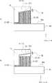
図1は、実施形態1に係る金属部材の製造方法において、金属部材及びサポート部材を例示した断面図である。 FIG. 1 is a cross-sectional view illustrating a metal member and a support member in the metal member manufacturing method according to the first embodiment.
図1に示すように、本実施形態では、金属部材10の製造過程において、金属部材10と共に、金属部材10におけるオーバーハング部11を支持するためのサポート部材20を形成する。なお、図1では、金属部材10におけるオーバーハング部11を含む部分のみが図示されており、金属部材10における他の部位については省略されている。 As shown in FIG. 1, in the present embodiment, in the manufacturing process of the
なお、オーバーハング部11とは、金属部材10において、下面11aが水平面に対して所定の角度以下、例えば、30°以下となる部分であり、金属部材10の3Dプリンタによる製造過程において、サポート部材20により下方から支持することが必要な部分である。 The
本実施形態に係る金属部材10の製造方法を、金属部材10及びサポート部材20の形成方法、並びに、サポート部材20の除去方法に分けて説明する。まず、金属部材10及びサポート部材20の形成方法を説明する。 The method for manufacturing the
金属部材10及びサポート部材20の製造方法では、まず、図1に示すように、台座40(ベースともいう。)を準備する。台座40は、例えば、板状の部材である。台座40の上面40aは水平である。図1において、説明の便宜上、XYZ直交座標系を導入する。Z方向が鉛直方向であり、台座40の上面40aと垂直な方向である。X方向及びY方向が水平方向であり、台座40の上面40aと平行な方向である。 In the manufacturing method of the
次に、台座40上に金属部材10の原料となる金属粉末を層状に敷き詰める。金属粉末は、例えば、マルエージング鋼、インコネル718等である。リコータを用いて台座40上に金属粉末を薄く、例えば、0.04mmの厚さの層状にして緻密に敷き詰める。そして、台座40上に敷き詰めた金属粉末層の所定領域に光ビームを照射し、選択的に溶融・凝固させた造形層を形成する。 Next, the metal powder used as the raw material of the
溶融・凝固させた造形層には、金属部材10及びサポート部材20のうちの少なくともいずれか1つの部材の断面形状が形成される。溶融・凝固させる部分は、STL形式の3Dデータをもとに、3Dプリンタにより制御する。溶融・凝固しない部分には、原料の金属粉末が残留する。 A cross-sectional shape of at least one of the
次に、造形層及び未溶融・未凝固の金属粉末上に、金属粉末を敷き詰める。そして、所定領域に光ビームを照射して造形層を形成する。このように、金属粉末の敷き詰め、及び、光ビームの照射を繰り返して造形層を積層させる。数十ミクロン単位で上方に造形層を積み上げる。所定の高さまで造形層を積み上げる。造形層を繰り返し形成することによって、オーバーハング部11を有する金属部材10を、オーバーハング部11を支持するサポート部材20と共に造形する。 Next, the metal powder is spread on the modeling layer and the unmelted / unsolidified metal powder. And a modeling layer is formed by irradiating a predetermined area with a light beam. In this way, the modeling layer is laminated by repeating the spreading of the metal powder and the irradiation of the light beam. Stack the modeling layer upwards in units of several tens of microns. The modeling layer is stacked up to a predetermined height. By repeatedly forming the modeling layer, the
本実施形態では、台座40上に造形層を積み上げて、金属部材10及びサポート部材20を形成するにあたって、まず、台座40の上面40a上に、正方ハニカム構造のサポート部材21を層状に形成する。正方ハニカム構造のサポート部材21は、上方に延びた複数個の中空の角柱が正方ハニカム構造となるように配列して一体形成されたものである。各角柱の一辺の長さは、例えば、1mmである。 In the present embodiment, when the modeling layer is stacked on the
次に、層状に形成したサポート部材21上に、金属部材10及び中実のサポート部材22を形成する。中実のサポート部材22は、内部に中空の部分を含まないサポート部材20である。なお、サポート部材20とは、ハニカム構造のサポート部材21及び中実のサポート部材22を総称したものをいう。 Next, the
中実のサポート部材22は、金属部材10のオーバーハング部11を支えるように、予め、オーバーハング部11の下方に位置するように形成する。この場合にも、中実のサポート部材22の形成位置を、STL形式の3Dデータをもとに、3Dプリンタにより制御する。このようにして、金属部材10の製造過程において、中実のサポート部材22を、台座40とオーバーハング部11との間に形成する。 The
オーバーハング部11の形成においては、オーバーハング部11とサポート部材20との境界面の略全体に0.3〜0.8mmのギャップ30を設ける。すなわち、オーバーハング部11の下面11aと、オーバーハング部11の下方に位置するサポート部材22の上面22aとの間の略全体に0.3〜0.8mmのギャップ30を設ける。ギャップ30が小さいため、ギャップ30は原料である金属粉末によって満たされている。金属粉末は未溶融・未凝固のままで残留している。したがって、オーバーハング部11は、未溶融・未凝固の金属粉末により支持される。このため、オーバーハング部11が殆ど傾くことがない。また、ギャップ30によりオーバーハング部11とサポート部材22とが分離されているため、サポート部材22を極めて容易に分離除去することができる。 In the formation of the
図2は、実施形態1に係るオーバーハング部の歪を例示したグラフであり、横軸は、オーバーハング部とサポート部材との間のギャップの設定値の大きさを示し、縦軸は、オーバーハング部の歪によるギャップの変化量を示す。位置1及び位置2は、オーバーハング部11における2つの異なる位置におけるギャップ30の変化量を示している。 FIG. 2 is a graph illustrating the distortion of the overhang portion according to the first embodiment, where the horizontal axis indicates the size of the set value of the gap between the overhang portion and the support member, and the vertical axis indicates the overhang portion. The amount of change of the gap due to distortion of the hang part is shown.
図2に示すように、オーバーハング部11とサポート部材20との間のギャップ30の設定値が大きくなるほど、オーバーハング部11の歪によるギャップ30の変化量が大きくなっている。逆に、ギャップ30の設定値が小さくなると、オーバーハング部11の歪によるギャップ30の変化量が小さくなる。 As shown in FIG. 2, as the set value of the
通常、金属粉末の粒径は数十μmである。ギャップ30における金属粉末の層の厚さが小さければ、ギャップ30内の金属粉末の層は、オーバーハング部11の造形時に、溶融部分の重力による下方への移動を抑制することができる。よって、ギャップ30の変化量を小さくすることができる。オーバーハング部11の歪による変形量(形状の変位、すなわち、3Dデータの設定値からのズレ)の許容値は、金属部材10全体の寸法精度との関係から、300μm以下が好ましい。よって、図2に示すように、オーバーハング部11とサポート部材20との間のギャップ30は、0.8mm以下が好ましい。 Usually, the particle size of the metal powder is several tens of μm. If the thickness of the metal powder layer in the
一方、オーバーハング部11とサポート部材20との間のギャップ30の設定値が0.3mmよりも小さいと、オーバーハング部11の造形時の溶融熱により、オーバーハング部11がサポート部材20に焼き付いてしまう。これにより、サポート部材20をオーバーハング部11から分離除去することが困難となる。よって、オーバーハング部11とサポート部材20との境界面の略全体に設けるギャップは、0.3〜0.8mmが好ましい。 On the other hand, when the set value of the
ギャップの設定値は、形成条件(金属粉末の金属の種類、粒度、レーザ出力、スキャン速度等)に応じて事前テストにより設定する。例えば、金属粉末がマルエージング鋼の場合には、平均粒径は、例えば30μmであり、レーザ出力は、例えば195Wである。ビーム径は、例えばφ0.1mmであり、レーザビームのスキャン速度は、例えば750mm/secである。 The set value of the gap is set by a preliminary test according to the forming conditions (metal type, particle size, laser output, scan speed, etc. of the metal powder). For example, when the metal powder is maraging steel, the average particle size is, for example, 30 μm, and the laser output is, for example, 195 W. The beam diameter is, for example, φ0.1 mm, and the scanning speed of the laser beam is, for example, 750 mm / sec.
このように、台座40上に敷き詰めた金属粉末層の所定領域に光ビームを照射して、選択的に溶融・凝固させた造形層を繰り返し形成することによって、オーバーハング部11を有する金属部材10を、オーバーハング部11を支持するサポート部材20と共に造形する。これにより、金属部材10及びサポート部材20を台座40上に形成することができる。 In this way, the
次に、サポート部材20の除去方法を説明する。まず、未溶融・未凝固の金属粉末を台座40上の金属部材10及びサポート部材20から払い出す。次に、金属部材10及びサポート部材20を台座40から切り離す。例えば、台座40の上面40aに沿ってバンドソー(平鋸)を配置させる。そして、バンドソーを、台座40の上面40aに沿って移動させる。これにより、一体形成された金属部材10及びサポート部材20を台座40から切り離す。次に、金属部材10からサポート部材20を分離除去する。例えば、把持用のペンチでサポート部材20を把持して引き剥がす。このようにして金属部材10が製造される。 Next, a method for removing the
本実施形態によれば、オーバーハング部11とサポート部材22との境界面の略全体に0.3〜0.8mmのギャップ30を設けるようにしている。ギャップ30が小さいため、金属粉末によりオーバーハング部11を支持することができる。そのため、オーバーハング部11が傾くことがない。また、ギャップ30により、オーバーハング部11とサポート部材22とが分離されているため、サポート部材22を極めて容易に分離除去することができる。 According to the present embodiment, the
また、本実施形態では、サポート部材22を、金属部材10と同じ金属粉末層から形成している。したがって、金属部材10及びサポート部材22を連続的に一体形成することができる。 In the present embodiment, the
さらに、本実施形態では、ギャップ30を挟んでオーバーハング部11と対向するサポート部材20を中実のサポート部材22としている。よって、ギャップ30を満たす金属粉末を、中実のサポート部材22の上面22aで支持している。中実のサポート部材22の上面22aには、未溶融・未凝固の金属粉末の部分が少ないので、ギャップ30内の金属粉末の流動を抑制することができる。よって、オーバーハング部11の造形時に溶融部分が重力によって下方に移動し、オーバーハング部11が変形することを抑制することができる。 Furthermore, in this embodiment, the
さらに、正方ハニカム構造のサポート部材21を、台座40と金属部材10との間に形成している。これにより、金属部材10及びサポート部材20を台座40から容易に切り離すことができる。 Further, a
(変形例1)
次に、実施形態1の変形例1に係る金属部材10の製造方法を説明する。
図3(a)は、実施形態1の変形例1に係る金属部材の製造方法おいて、金属部材及びサポート部材を例示した断面図である。実施形態1において、オーバーハング部11を支持するサポート部材20は、中実のサポート部材22であったが、本変形例1では、オーバーハング部11を支持するサポート部材20は、正方ハニカム構造のサポート部材21としている。(Modification 1)
Next, a method for manufacturing the
FIG. 3A is a cross-sectional view illustrating a metal member and a support member in the method for manufacturing a metal member according to the first modification of the first embodiment. In the first embodiment, the
本変形例1の金属部材10の製造方法において、台座40の上面40a上に、正方ハニカム構造のサポート部材21を層状に形成することは、実施形態1と同様である。次に、層状に形成したサポート部材21上に、金属部材10及び正方ハニカム構造のサポート部材21を形成する。 In the method for manufacturing the
正方ハニカム構造のサポート部材21は、金属部材10のオーバーハング部11を支えるように、予め、オーバーハング部11の下方に位置するように形成する。この場合にも、STL形式の3Dデータをもとに、3Dプリンタにより制御する。 The
このようにして、正方ハニカム構造のサポート部材21を、台座40とオーバーハング部11との間に形成する。そして、オーバーハング部11とサポート部材21との境界面の略全体に0.3〜0.8mmのギャップ30を設ける。 In this way, the
ハニカム構造のサポート部材21は、中実のサポート部材22に比べて、金属粉末をレーザで照射して溶融させる部分を小さくすることができる。よって、レーザの照射時間を短縮することができる。これにより、変形例1においては、製造に要する時間を短縮することができる。 Compared to the
サポート部材20を正方ハニカム構造のサポート部材21とすることにより、サポート部材21に、剛性を持たせ、オーバーハング部11を支持させることができる。それと同時に、サポート部材21を除去しやすいものとすることができる。 By using the
なお、正方ハニカム構造を細かなもの(角柱の一辺の長さを1mm以下)とすれば、ギャップ30内の金属粉末の流動を、中実のサポート部材22の場合と同様程度まで抑制することができる。そして、オーバーハング部11の造形時に溶融部分が重力によって下方に移動し、オーバーハング部11が変形することを抑制することができる。その他の効果は、実施形態1と同様である。 If the square honeycomb structure is made fine (the length of one side of the prism is 1 mm or less), the flow of the metal powder in the
(変形例2)
次に、実施形態1の変形例2に係る金属部材10の製造方法を説明する。
図3(b)は、実施形態1の変形例2に係る金属部材の製造方法おいて、金属部材及びサポート部材を例示した断面図である。実施形態1において、オーバーハング部11を支持するサポート部材20は、中実のサポート部材22であった。しかしながら、図3(b)に示すように、本変形例2では、オーバーハング部11を支持するサポート部材20は、正方ハニカム構造のサポート部材21と、中実のサポート部材22とを含んでいる。ギャップ30を挟んでオーバーハング部11と対向する部分には、中実のサポート部材22を配置する。これにより、オーバーハング部11の造形時に溶融部分が重力によって下方に移動し、ギャップ30内の金属粉末が流動すること、及び、オーバーハング部11が変形することを抑制することができる。(Modification 2)
Next, a method for manufacturing the
FIG. 3B is a cross-sectional view illustrating the metal member and the support member in the method for manufacturing the metal member according to the second modification of the first embodiment. In the first embodiment, the
一方、ギャップ30を挟んでオーバーハング部11と対向する部分以外の部分、例えば、中実のサポート部材22の下方には、正方ハニカム構造のサポート部材21を形成する。これにより、製造に要する時間を短縮することができる。その他の効果は、実施形態1と同様である。 On the other hand, a
(実施形態2)
次に、実施形態2に係る金属部材10の製造方法を説明する。本実施形態は、中空部分を有する金属部材の製造方法についてのものである。中空部分の上方にもオーバーハング部11が形成されている。(Embodiment 2)
Next, a method for manufacturing the
図4は、実施形態2に係る金属部材の製造方法において、金属部材及びサポート部材を例示した図であり、(a)は、斜視図であり、(b)は、上面図であり、(c)は、側面図である。 4A and 4B are diagrams illustrating a metal member and a support member in the metal member manufacturing method according to the second embodiment, wherein FIG. 4A is a perspective view, FIG. 4B is a top view, and FIG. ) Is a side view.
図4(a)〜(c)に示すように、金属部材10は、中空部分12を有している。中空部分12は、例えば、中心軸がY軸方向に延びた円柱の形状となっている。中空部分12の上方には、オーバーハング部11が形成されている。なお、図4(a)〜(c)では、金属部材10におけるオーバーハング部11を含む部分のみが図示されており、金属部材10における他の部位については省略されている。 As shown in FIGS. 4A to 4C, the
中空部分12の内部には、中実のサポート部材22が設けられている。サポート部材22は、上面22a及び下面が、中空部分12の内面に嵌合した略直方体の形状をしている。サポート部材22は、オーバーハング部11の下方に配置されている。サポート部材22の+X軸方向側及び−X軸方向側は中空のままとなっている。サポート部材22の上面22aは、ギャップ30を介してオーバーハング部11の下面11aに対向している。オーバーハング部11とサポート部材22との境界面の略全体に0.3〜0.8mmのギャップが設けられている。オーバーハング部11とサポート部材22と間のギャップ30は、金属粉末で満たされている。 A
また、サポート部材22と、中空部分12の下方の金属部材10との間にもギャップ32が設けられている。ギャップ32は、例えば、0.3〜0.8mmとなっている。ギャップ32は、例えば、ハニカム構造もしくはハニカム構造以外の任意の構造のサポート部材20を含むアンカー膜(図示せず)により構成されている。 A
図4(b)に示すように、サポート部材22には、Y軸方向に垂直な面で構成された4つの分割溝31が設けられている。分割溝31は、0.3〜0.8mm、例えば、0.5mmのギャップ30となっている。これにより、サポート部材22は上方から見て5つの部分23に分割されている。このように、各部分23は、分割溝31を介して層状に形成されている。 As shown in FIG. 4B, the
さらに、図4(a)及び(c)に示すように、分割された各部材23は、上部23a、中部23b、下部23cにそれぞれ分割溝31により分割されている。中部23bは、正面側(−Y軸方向側)から取り出しやすいように、正面側の面が、奥側(+Y軸方向側)の面よりも広くなった楔形の形状となっている。上部23a及び下部23cは、奥側の面が正面側の面より広くなった台形の形状となっている。上部23a、中部23b、下部23cにおいて、+X軸方向側の面及び−X軸方向側の面には、引き剥がし用のフランジ24が設けられている。 Further, as shown in FIGS. 4A and 4C, each divided
次に、実施形態2に係る金属部材10の製造方法を説明する。まず、金属部材10及びサポート部材22の形成方法を説明する。図4(a)〜(c)に示すように、造形層を繰り返し形成することによって、中空部分12及びオーバーハング部11を有する金属部材10を、オーバーハング部11を支持するサポート部材22と共に造形する。これにより、台座40上に、金属部材10及びサポート部材22を形成する。サポート部材22を形成する際には、分割溝31を含むように形成する。このようにして、サポート部材22を複数に分割して形成する。上述の実施形態1と同様に、STL形式の3Dデータをもとに、3Dプリンタにより制御する。 Next, a method for manufacturing the
次に、サポート部材22の除去方法を説明する。まず、未溶融・未凝固の金属粉末を台座40上の金属部材10及びサポート部材20から払い出す。次に、金属部材10及びサポート部材20を台座40から切り離す。次に、金属部材10からサポート部材20を分離除去する。なお、中空部分12の内部のサポート部材22を金属部材10から分離除去した後に、金属部材10及びサポート部材20を台座40から切り離してもよい。 Next, a method for removing the
図5(a)〜(c)は、実施形態2に係るサポート部材の除去方法を例示した側面図である。 FIGS. 5A to 5C are side views illustrating a method for removing a support member according to the second embodiment.
図4(a)及び図5(a)に示すように、サポート部材22の+X軸方向側及び−X軸方向側の隙間より、把持用のペンチで中部23bに設けられたフランジ24を掴み、中部23bをサポート部材22から引き剥がす。中部23bを一つ引き剥がすと、その部分が隙間となる。 As shown in FIG. 4A and FIG. 5A, the
次に、図5(b)に示すように、中部23bを引き剥がした後は、同様に、上部23aのフランジ24を把持用のペンチで掴み、上部23aを引き剥がす。その後で、図5(c)に示すように、下部23cのフランジ24を把持用のペンチで掴み、下部23cを引き剥がす。なお、上部23aと下部23cとの引き剥がす順番を逆にしてもよい。 Next, as shown in FIG. 5B, after the
本実施形態によれば、中空部分12を有する金属部材10を、3Dプリンタにより形成することができる。また、中空部分12の上方に位置するオーバーハング部11を、オーバーハング部11を支持するサポート部材22と共に形成することができる。 According to this embodiment, the
例えば、指向性エネルギー堆積法(Direct Metal Deposition)で焼成しながら、焼成体を、専用機のB軸及びC軸で変位させ、オーバーハング状態にならないように焼成させる方法がある。しかし、そのような方法では、中空部分12を有する金属部材10や、立体交差を有する金属部材10を形成することができない。 For example, there is a method in which a fired body is displaced by the B-axis and C-axis of a dedicated machine and fired so as not to be overhanged while being fired by a directional energy deposition method (Direct Metal Deposition). However, such a method cannot form the
しかしながら、本実施形態では、上述のように、中空部分12を有する金属部材10を形成することができ、この製造方法を応用すれば、立体交差を有する金属部材10も形成することができる。自動車部品等では、機能上、中空部分12や立体交差形状が必要となるので、本実施形態を、自動車部品の製造に適用することができる。 However, in the present embodiment, as described above, the
また、本実施形態では、サポート部材22を複数に分割して形成している。すなわち、サポート部材22を、分割溝31により、小さな部分23に分割している。そして、正面側の部分23から、順番に引き剥がすことにより、サポート部材22を小さな部分23として引き剥がすことができる。よって、サポート部材22の分離除去をさらに容易にすることができる。また、引き剥がす際に必要な力を小さくすることができる。これ以外の効果は、実施形態1と同様である。 In the present embodiment, the
(実施形態3)
図6は、実施形態3に係る金属部材の製造方法において、金属部材及びサポート部材を例示した図であり、(a)は、正面図であり、(b)は、(a)におけるAの拡大図であり、(c)は、上面図であり、(d)は、側面図である。(Embodiment 3)
FIG. 6 is a diagram illustrating a metal member and a support member in the method for manufacturing a metal member according to Embodiment 3, wherein (a) is a front view, and (b) is an enlarged view of A in (a). It is a figure, (c) is a top view, (d) is a side view.
図6(a)〜(d)に示すように、金属部材10は、中央に中空部分12を有し、中空部分12の上方には、オーバーハング部11が形成されている。中空部分12の内部には、中実のサポート部材22が設けられている。 As shown in FIGS. 6A to 6D, the
オーバーハング部11とサポート部材22との境界面の略全体には、0.3〜0.8mmのギャップ30が設けられている。オーバーハング部11とサポート部材22と間のギャップ30は、金属粉末で満たされている。 A
サポート部材22と、中空部分12の下方の金属部材10との間にもギャップ32が設けられている。ギャップ32は、例えば、0.3〜0.8mmとなっている。ギャップ32は、例えば、ハニカム構造もしくはハニカム構造以外の任意の構造のサポート部材20を含むアンカー膜25により構成されている。 A
図6(c)及び(d)に示すように、サポート部材22は、実施形態2と同様に、分割溝31により、上方から見て5つの部分23に分割されている。図6(a)及び(d)に示すように、分割された各部材23は、分割溝31によって、上部23aと下部23cとに分割されている。上部23a及び下部23cにはフランジ24が設けられていない。 As shown in FIGS. 6C and 6D, the
しかしながら、上部23a及び下部23cの正面側の面には凹部26が設けられている。凹部26は正面から見て、例えば、四角形の形状をしている。四角形の対角線がX軸方向及びZ軸方向を向いている。よって、凹部26の側面の内、下方に向いた面26aと、水平面との角度は、例えば、30°以上となっており、オーバーハング部11とならないようになっている。その他の構成は実施形態2と同様である。なお、凹部26の形状は、四角形に限らない。六角穴、星型穴でもよい。 However, a
次に、実施形態3に係る金属部材10の製造方法を説明する。まず、金属部材10及びサポート部材22の形成方法を説明する。図6(a)〜(d)に示すように、造形層を繰り返し形成することによって、中空部分12及びオーバーハング部11を有する金属部材10を、オーバーハング部11を支持するサポート部材22と共に造形する。これにより、台座40上に、金属部材10及びサポート部材22を形成する。サポート部材22を形成する際には、分割溝31及び凹部26を含むように形成する。本実施形態でも、サポート部材22を複数に分割して形成する。上述の実施形態1と同様に、STL形式の3Dデータをもとに、3Dプリンタにより制御する。 Next, a method for manufacturing the
次に、サポート部材22の除去方法を説明する。まず、未溶融・未凝固の金属粉末を台座40上の金属部材10及びサポート部材20から払い出し、金属部材10及びサポート部材20を台座40から切り離すまでは実施形態2と同様である。 Next, a method for removing the
次に、金属部材10からサポート部材20を分離除去する。サポート部材22に形成された凹部26にレンチ等を挿入する。そして、レンチを捩ることにより、サポート部材22を金属部材10から分離除去する。なお、中空部分12の内部のサポート部材22を金属部材10から分離除去した後に、金属部材10及びサポート部材20を台座40から切り離してもよい。 Next, the
本実施形態によれば、サポート部材22に形成させた凹部26にレンチ等を挿入し、レンチを捩ることにより、サポート部材22の各部分を分離除去することができる。よって、サポート部材22を極めて容易に分離除去することができる。また、フランジ24を形成する必要がないので、製造時間を短縮することができる。それ以外の効果は、実施形態1及び2と同様である。 According to this embodiment, each part of the
以上、本発明に係る金属部材の製造方法についての実施の形態を説明したが、上記の構成に限らず、本発明の技術的思想を逸脱しない範囲で、変更することが可能である。 As mentioned above, although embodiment about the manufacturing method of the metal member which concerns on this invention was described, it can change in the range which does not deviate not only from said structure but the technical idea of this invention.
例えば、サポート部材20として、ハニカム構造のサポート部材21及び中実のサポート部材22を示したが、これらに限らない。オーバーハング部11を支持できれば、任意の形状のサポート部材20を用いてもよい。また、上述の実施形態において、ハニカム構造のサポート部材21の代わりに、中実のサポート部材22を用いてもよいし、その逆でもよい。 For example, as the
10 金属部材
11 オーバーハング部
11a 下面
12 中空部分
20、21、22 サポート部材
22a 上面
23 部分
23a 上部
23b 中部
23c 下部
24 フランジ
25 アンカー膜
26 凹部
26a 面
30、32 ギャップ
31 分割溝
40 台座
40a 上面DESCRIPTION OF
Claims (2)
Translated fromJapanese前記オーバーハング部と前記サポート部材との境界面の略全体に0.3〜0.8mmのギャップを設ける、
金属部材の製造方法。By irradiating a predetermined region of the metal powder layer spread on the pedestal with a light beam and repeatedly forming a molding layer that is selectively melted and solidified, a metal member having an overhang portion is formed by replacing the overhang portion with the overhang portion. A method for manufacturing a metal member, which is shaped together with a supporting member to be supported,
A gap of 0.3 to 0.8 mm is provided in substantially the entire boundary surface between the overhang portion and the support member.
A method for producing a metal member.
Priority Applications (1)
| Application Number | Priority Date | Filing Date | Title |
|---|---|---|---|
| JP2016009670AJP6504064B2 (en) | 2016-01-21 | 2016-01-21 | Method of manufacturing metal member |
Applications Claiming Priority (1)
| Application Number | Priority Date | Filing Date | Title |
|---|---|---|---|
| JP2016009670AJP6504064B2 (en) | 2016-01-21 | 2016-01-21 | Method of manufacturing metal member |
Publications (2)
| Publication Number | Publication Date |
|---|---|
| JP2017128770Atrue JP2017128770A (en) | 2017-07-27 |
| JP6504064B2 JP6504064B2 (en) | 2019-04-24 |
Family
ID=59395429
Family Applications (1)
| Application Number | Title | Priority Date | Filing Date |
|---|---|---|---|
| JP2016009670AExpired - Fee RelatedJP6504064B2 (en) | 2016-01-21 | 2016-01-21 | Method of manufacturing metal member |
Country Status (1)
| Country | Link |
|---|---|
| JP (1) | JP6504064B2 (en) |
Cited By (9)
| Publication number | Priority date | Publication date | Assignee | Title |
|---|---|---|---|---|
| CN108161007A (en)* | 2017-12-29 | 2018-06-15 | 广州瑞通激光科技有限公司 | A kind of metal parts optimization method of SLM moldings overhung structure |
| CN108746617A (en)* | 2018-06-18 | 2018-11-06 | 重庆恩光科技有限公司 | Selective laser melting device with electromagnetic location power spreading device |
| WO2019111347A1 (en)* | 2017-12-06 | 2019-06-13 | 株式会社Fuji | Method for forming supporting member and method for forming structure |
| WO2019124296A1 (en)* | 2017-12-18 | 2019-06-27 | 日立金属株式会社 | Additively manufactured article, method for manufacturing same, and metal powder for additive manufacturing |
| CN112059185A (en)* | 2020-11-11 | 2020-12-11 | 中国航发上海商用航空发动机制造有限责任公司 | Molded article with cantilever structure and method of molding the same |
| JP2022060683A (en)* | 2020-10-05 | 2022-04-15 | 株式会社荏原製作所 | Information processing systems, methods and programs |
| US11370030B2 (en) | 2019-04-05 | 2022-06-28 | Sodick Co., Ltd. | Manufacturing method for three-dimensional molded object, lamination molding apparatus, and three-dimensional molded object |
| JP2023011787A (en)* | 2018-01-23 | 2023-01-24 | ローカル モーターズ アイピー,エルエルシー | Additively manufactured structure and method for forming the same |
| EP4321281A1 (en)* | 2022-08-11 | 2024-02-14 | Rolls-Royce plc | A method of manufacturing a component |
Families Citing this family (1)
| Publication number | Priority date | Publication date | Assignee | Title |
|---|---|---|---|---|
| CN112059186B (en)* | 2020-11-11 | 2021-01-15 | 中国航发上海商用航空发动机制造有限责任公司 | Molded article with inclined surface and molding method thereof |
Citations (1)
| Publication number | Priority date | Publication date | Assignee | Title |
|---|---|---|---|---|
| JP2015009495A (en)* | 2013-06-28 | 2015-01-19 | シーメット株式会社 | Three-dimensional structure and support forming method |
- 2016
- 2016-01-21JPJP2016009670Apatent/JP6504064B2/ennot_activeExpired - Fee Related
Patent Citations (1)
| Publication number | Priority date | Publication date | Assignee | Title |
|---|---|---|---|---|
| JP2015009495A (en)* | 2013-06-28 | 2015-01-19 | シーメット株式会社 | Three-dimensional structure and support forming method |
Cited By (17)
| Publication number | Priority date | Publication date | Assignee | Title |
|---|---|---|---|---|
| WO2019111347A1 (en)* | 2017-12-06 | 2019-06-13 | 株式会社Fuji | Method for forming supporting member and method for forming structure |
| JPWO2019111347A1 (en)* | 2017-12-06 | 2020-10-22 | 株式会社Fuji | Method of forming a support member and method of forming a structure |
| CN111448020B (en)* | 2017-12-18 | 2022-07-12 | 日立金属株式会社 | Layered product, method for producing same, and metal powder for layered product |
| JPWO2019124296A1 (en)* | 2017-12-18 | 2019-12-19 | 日立金属株式会社 | Laminated object and method of manufacturing the same |
| CN111448020A (en)* | 2017-12-18 | 2020-07-24 | 日立金属株式会社 | Layered structure, method for producing same, and metal powder for layered structure |
| WO2019124296A1 (en)* | 2017-12-18 | 2019-06-27 | 日立金属株式会社 | Additively manufactured article, method for manufacturing same, and metal powder for additive manufacturing |
| US11643711B2 (en) | 2017-12-18 | 2023-05-09 | Hitachi Metals, Ltd. | Laminate shaped article, method for manufacturing the same, and metal powder for laminate shaping |
| CN108161007A (en)* | 2017-12-29 | 2018-06-15 | 广州瑞通激光科技有限公司 | A kind of metal parts optimization method of SLM moldings overhung structure |
| JP2023011787A (en)* | 2018-01-23 | 2023-01-24 | ローカル モーターズ アイピー,エルエルシー | Additively manufactured structure and method for forming the same |
| CN108746617A (en)* | 2018-06-18 | 2018-11-06 | 重庆恩光科技有限公司 | Selective laser melting device with electromagnetic location power spreading device |
| US11370030B2 (en) | 2019-04-05 | 2022-06-28 | Sodick Co., Ltd. | Manufacturing method for three-dimensional molded object, lamination molding apparatus, and three-dimensional molded object |
| JP2022060683A (en)* | 2020-10-05 | 2022-04-15 | 株式会社荏原製作所 | Information processing systems, methods and programs |
| JP7550593B2 (en) | 2020-10-05 | 2024-09-13 | 株式会社荏原製作所 | Information processing system, method and program |
| WO2022100397A1 (en)* | 2020-11-11 | 2022-05-19 | 中国航发上海商用航空发动机制造有限责任公司 | Forming part having cantilever structure and forming method therefor |
| CN112059185B (en)* | 2020-11-11 | 2021-01-15 | 中国航发上海商用航空发动机制造有限责任公司 | Molded article with cantilever structure and method of molding the same |
| CN112059185A (en)* | 2020-11-11 | 2020-12-11 | 中国航发上海商用航空发动机制造有限责任公司 | Molded article with cantilever structure and method of molding the same |
| EP4321281A1 (en)* | 2022-08-11 | 2024-02-14 | Rolls-Royce plc | A method of manufacturing a component |
Also Published As
| Publication number | Publication date |
|---|---|
| JP6504064B2 (en) | 2019-04-24 |
Similar Documents
| Publication | Publication Date | Title |
|---|---|---|
| JP6504064B2 (en) | Method of manufacturing metal member | |
| JP6500047B2 (en) | Method for additive manufacturing and connection support | |
| JP6496758B2 (en) | Method and conformal support for additive manufacturing | |
| EP2986406B1 (en) | Build platform, apparatus and method for additive manufacturing | |
| JP6420855B2 (en) | Method for additive manufacturing | |
| EP3626370B1 (en) | Methods and keyway supports for additive manufacturing | |
| US10046524B2 (en) | Substrate for additive manufacturing | |
| US11173668B2 (en) | Methods and rail supports for additive manufacturing | |
| US10357828B2 (en) | Methods and leading edge supports for additive manufacturing | |
| JP6358206B2 (en) | Method for manufacturing metal member | |
| US9789540B2 (en) | Method of forming an article | |
| JP5119123B2 (en) | Manufacturing method of three-dimensional shaped object | |
| WO2015133138A1 (en) | Method for producing three-dimensionally shaped object | |
| JP2018095946A (en) | Manufacturing method of three-dimensional structure and three-dimensional modeling apparatus | |
| CN105834421B (en) | Method for producing a component and component | |
| US10792906B2 (en) | Additive manufacturing | |
| JP2018031037A (en) | Method for molding metallic component | |
| JP4639133B2 (en) | 3D modeling method | |
| JP7215964B2 (en) | Anisotropic composite material molding method, mold using anisotropic composite material |
Legal Events
| Date | Code | Title | Description |
|---|---|---|---|
| A621 | Written request for application examination | Free format text:JAPANESE INTERMEDIATE CODE: A621 Effective date:20180214 | |
| A977 | Report on retrieval | Free format text:JAPANESE INTERMEDIATE CODE: A971007 Effective date:20181122 | |
| A131 | Notification of reasons for refusal | Free format text:JAPANESE INTERMEDIATE CODE: A131 Effective date:20181211 | |
| A521 | Request for written amendment filed | Free format text:JAPANESE INTERMEDIATE CODE: A523 Effective date:20181220 | |
| TRDD | Decision of grant or rejection written | ||
| A01 | Written decision to grant a patent or to grant a registration (utility model) | Free format text:JAPANESE INTERMEDIATE CODE: A01 Effective date:20190226 | |
| A61 | First payment of annual fees (during grant procedure) | Free format text:JAPANESE INTERMEDIATE CODE: A61 Effective date:20190311 | |
| R151 | Written notification of patent or utility model registration | Ref document number:6504064 Country of ref document:JP Free format text:JAPANESE INTERMEDIATE CODE: R151 | |
| LAPS | Cancellation because of no payment of annual fees |