JP2017123995A - High-frequency treatment instrument for endoscope - Google Patents
High-frequency treatment instrument for endoscopeDownload PDFInfo
- Publication number
- JP2017123995A JP2017123995AJP2016004573AJP2016004573AJP2017123995AJP 2017123995 AJP2017123995 AJP 2017123995AJP 2016004573 AJP2016004573 AJP 2016004573AJP 2016004573 AJP2016004573 AJP 2016004573AJP 2017123995 AJP2017123995 AJP 2017123995A
- Authority
- JP
- Japan
- Prior art keywords
- knife
- tip
- frequency
- wire
- endoscope
- Prior art date
- Legal status (The legal status is an assumption and is not a legal conclusion. Google has not performed a legal analysis and makes no representation as to the accuracy of the status listed.)
- Granted
Links
- 238000011282treatmentMethods0.000titleclaimsabstractdescription106
- 238000003780insertionMethods0.000claimsdescription5
- 230000037431insertionEffects0.000claimsdescription5
- 210000004400mucous membraneAnatomy0.000description35
- 238000000034methodMethods0.000description25
- 238000000576coating methodMethods0.000description18
- 239000007788liquidSubstances0.000description18
- 239000011248coating agentSubstances0.000description17
- 230000003373anti-fouling effectEffects0.000description15
- 206010040844Skin exfoliationDiseases0.000description13
- 239000007924injectionSubstances0.000description12
- 238000002347injectionMethods0.000description12
- 230000003902lesionEffects0.000description11
- 230000023597hemostasisEffects0.000description10
- XLYOFNOQVPJJNP-UHFFFAOYSA-NwaterSubstancesOXLYOFNOQVPJJNP-UHFFFAOYSA-N0.000description9
- 230000000740bleeding effectEffects0.000description8
- 210000004877mucosaAnatomy0.000description7
- 238000004299exfoliationMethods0.000description5
- 239000002184metalSubstances0.000description5
- 102000004169proteins and genesHuman genes0.000description5
- 108090000623proteins and genesProteins0.000description5
- 230000005855radiationEffects0.000description5
- 238000010586diagramMethods0.000description4
- 230000009854mucosal lesionEffects0.000description4
- 239000000243solutionSubstances0.000description4
- 238000005406washingMethods0.000description4
- 208000025865UlcerDiseases0.000description3
- 238000004140cleaningMethods0.000description3
- 238000012277endoscopic treatmentMethods0.000description3
- 230000012447hatchingEffects0.000description3
- 230000002093peripheral effectEffects0.000description3
- 231100000397ulcerToxicity0.000description3
- 238000012323Endoscopic submucosal dissectionMethods0.000description2
- VYPSYNLAJGMNEJ-UHFFFAOYSA-NSilicium dioxideChemical compoundO=[Si]=OVYPSYNLAJGMNEJ-UHFFFAOYSA-N0.000description2
- 230000002439hemostatic effectEffects0.000description2
- 239000000463materialSubstances0.000description2
- -1polytetrafluoroethylenePolymers0.000description2
- 229920001343polytetrafluoroethylenePolymers0.000description2
- 239000004810polytetrafluoroethyleneSubstances0.000description2
- 230000001105regulatory effectEffects0.000description2
- 239000000126substanceSubstances0.000description2
- 210000004876tela submucosaAnatomy0.000description2
- 210000001519tissueAnatomy0.000description2
- OKTJSMMVPCPJKN-UHFFFAOYSA-NCarbonChemical compound[C]OKTJSMMVPCPJKN-UHFFFAOYSA-N0.000description1
- 206010009944Colon cancerDiseases0.000description1
- 208000001333Colorectal NeoplasmsDiseases0.000description1
- 208000000461Esophageal NeoplasmsDiseases0.000description1
- 102000001554HemoglobinsHuman genes0.000description1
- 108010054147HemoglobinsProteins0.000description1
- 206010030155Oesophageal carcinomaDiseases0.000description1
- 239000004809TeflonSubstances0.000description1
- 229920006362Teflon®Polymers0.000description1
- 230000004308accommodationEffects0.000description1
- 238000005452bendingMethods0.000description1
- 210000004369bloodAnatomy0.000description1
- 239000008280bloodSubstances0.000description1
- 238000005219brazingMethods0.000description1
- 229910052799carbonInorganic materials0.000description1
- 239000004020conductorSubstances0.000description1
- 238000003618dip coatingMethods0.000description1
- 239000003814drugSubstances0.000description1
- 229940079593drugDrugs0.000description1
- 230000000694effectsEffects0.000description1
- 201000004101esophageal cancerDiseases0.000description1
- 150000002222fluorine compoundsChemical class0.000description1
- 239000003550markerSubstances0.000description1
- 239000008155medical solutionSubstances0.000description1
- 201000011591microinvasive gastric cancerDiseases0.000description1
- 238000012986modificationMethods0.000description1
- 230000004048modificationEffects0.000description1
- 150000003961organosilicon compoundsChemical class0.000description1
- 239000002504physiological saline solutionSubstances0.000description1
- 229920001296polysiloxanePolymers0.000description1
- 238000003825pressingMethods0.000description1
- 239000011347resinSubstances0.000description1
- 229920005989resinPolymers0.000description1
- 238000000926separation methodMethods0.000description1
- 239000000377silicon dioxideSubstances0.000description1
- 229910052814silicon oxideInorganic materials0.000description1
- 238000004528spin coatingMethods0.000description1
- 239000007921spraySubstances0.000description1
- 238000005507sprayingMethods0.000description1
- 238000003466weldingMethods0.000description1
Images


Classifications
- A—HUMAN NECESSITIES
- A61—MEDICAL OR VETERINARY SCIENCE; HYGIENE
- A61B—DIAGNOSIS; SURGERY; IDENTIFICATION
- A61B18/00—Surgical instruments, devices or methods for transferring non-mechanical forms of energy to or from the body
- A61B18/04—Surgical instruments, devices or methods for transferring non-mechanical forms of energy to or from the body by heating
- A61B18/12—Surgical instruments, devices or methods for transferring non-mechanical forms of energy to or from the body by heating by passing a current through the tissue to be heated, e.g. high-frequency current
- A61B18/14—Probes or electrodes therefor
Landscapes
- Health & Medical Sciences (AREA)
- Surgery (AREA)
- Engineering & Computer Science (AREA)
- Life Sciences & Earth Sciences (AREA)
- Biomedical Technology (AREA)
- Otolaryngology (AREA)
- Nuclear Medicine, Radiotherapy & Molecular Imaging (AREA)
- Plasma & Fusion (AREA)
- Physics & Mathematics (AREA)
- Heart & Thoracic Surgery (AREA)
- Medical Informatics (AREA)
- Molecular Biology (AREA)
- Animal Behavior & Ethology (AREA)
- General Health & Medical Sciences (AREA)
- Public Health (AREA)
- Veterinary Medicine (AREA)
- Surgical Instruments (AREA)
Abstract
Description
Translated fromJapanese本発明は、内視鏡の処置具挿通チャンネルに挿入されて使用される内視鏡用高周波処置具に関する。 The present invention relates to an endoscope high-frequency treatment instrument that is used by being inserted into a treatment instrument insertion channel of an endoscope.
早期食道癌、早期胃癌、早期大腸癌等の広範囲に及ぶ病変部を内視鏡を用いて確実に一括切除することが可能な方法として、内視鏡的粘膜下層剥離術(Endoscopic Submucosal Dissection(以下、「ESD」という。)が知られている。ESDの手技は、(1)病変部の切除範囲にマーキングを施し(マーキング)、(2)粘膜下層に薬液を局所注射して粘膜病変部を隆起させ(局注)、(3)マーキングに従って粘膜病変部の周囲を切開した後、粘膜下層を剥離し(切開・剥離)、(4)剥離した潰瘍面や切開、剥離時に発生した出血を止血する(止血)、といった処置(工程)よりなる。ESDの各工程では、専用のディスポーザブル内視鏡用処置具が使用される。例えば特許文献1に記載されているように、切開・剥離の工程では、高周波電流を通電して粘膜等を切除するニードルナイフ等を備えた内視鏡用処置具が使用される。 Endoscopic submucosal dissection (hereinafter referred to as endoscopic submucosal dissection) is a method that can reliably remove a wide range of lesions such as early esophageal cancer, early gastric cancer, and early colorectal cancer using an endoscope. The ESD technique consists of (1) marking the excision area of the lesion (marking), and (2) locally injecting a drug solution into the submucosa to remove the mucosal lesion. Protrusions (local injection), (3) Incision around the mucosal lesion according to the marking, then exfoliate the submucosal layer (incision / exfoliation), and (4) stop bleeding from the ulcer surface, incision, and exfoliation In each ESD process, a dedicated disposable endoscope treatment tool is used, for example, an incision / exfoliation process as described in
ESDは、広範囲の病変部を一括切除する治療方法であるため、治療時間が長く、手技的難易度も高い。そのため、粘膜等の切除を行う際、出血を伴うことが多い。術者は、手技中に出血が生じると、切開・剥離用の内視鏡用処置具を体腔内から一旦取り出し、止血用の内視鏡用処置具に差し替えて、内視鏡的止血術を行う必要がある。すなわち、ESDでは、用途に応じた(各工程に応じた)複数のディスポーザブル専用処置具が必要であり、また、予期せぬ出血等があるとそれに応じた対処が必要となる。そのため、コスト及び手技時間の観点から、複数の処置(工程)に対応できる内視鏡用処置具が望まれていた。 ESD is a treatment method for excision of a wide range of lesions in a lump, so that the treatment time is long and the technical difficulty is high. Therefore, bleeding is often accompanied when excising the mucous membrane. When bleeding occurs during the procedure, the operator temporarily removes the endoscopic treatment tool for incision and detachment from the body cavity and replaces it with an endoscopic treatment tool for hemostasis to perform endoscopic hemostasis. There is a need to do. In other words, ESD requires a plurality of disposable treatment tools according to the application (according to each process), and if there is an unexpected bleeding or the like, it is necessary to take measures accordingly. Therefore, from the viewpoint of cost and procedure time, an endoscope treatment tool that can cope with a plurality of treatments (steps) has been desired.
そこで、特許文献2において、ESDの複数の処置に使用することが可能な内視鏡用高周波処置具が提案されている。 Therefore, Patent Document 2 proposes an endoscopic high-frequency treatment instrument that can be used for a plurality of ESD treatments.
特許文献2に記載の内視鏡用高周波処置具は、可撓性シースの先端面からの突出量が変化するナイフ部を備えている。ナイフ部は、前進操作されると、突出量が切開や剥離の処置に適した2mm程度となる位置で停止し、後退操作されると、突出量がマーキングや止血の処置に適した0.5mm程度となる位置で停止する。ナイフ部の突出量をESDの各処置に応じて変化させることにより、これらの処置中に内視鏡用処置具を差し替える必要がなくなる。そのため、手技の作業性が高められて、手技時間が短縮される。 The endoscope high-frequency treatment tool described in Patent Literature 2 includes a knife portion that changes the amount of protrusion from the distal end surface of the flexible sheath. When the knife part is operated forward, it stops at a position where the protruding amount is about 2 mm suitable for incision and peeling treatment, and when it is retracted, the protruding amount is 0.5 mm suitable for marking and hemostasis treatment. Stop at the appropriate position. By changing the protruding amount of the knife portion in accordance with each treatment of ESD, it is not necessary to replace the endoscope treatment tool during these treatments. Therefore, the workability of the procedure is improved and the procedure time is shortened.
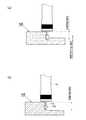
図11(a)は、特許文献2に記載の内視鏡用高周波処置具を用いて粘膜病変部の周囲を切開している状態を示す図である。図11(a)に示されるように、特許文献2に記載の内視鏡用高周波処置具では、突起部材によって粘膜が押されることにより、ナイフ部の先端部分に粘膜が接触しないことがある。ナイフ部の先端部分が粘膜に接触しない場合、先端部分による粘膜の切開が行われないため、切開される粘膜の深さが浅くなる。ナイフ部の先端部分で切開できなかった粘膜を切開するには、ナイフ部を前回よりも深い位置に差し込んだうえで同様の作業を繰り返す必要がある。そのため、切開の回数が増えて、手技時間が長くなるという問題が指摘される。この問題を解決するため、ナイフ部の全長を長くすることが考えられる。しかし、この場合、粘膜穿孔等が発生する虞があるため、ナイフ部の全長を長くすることは難しい。 FIG. 11A is a diagram showing a state in which the periphery of the mucosal lesion is incised using the endoscope high-frequency treatment tool described in Patent Document 2. FIG. As shown in FIG. 11A, in the endoscope high-frequency treatment instrument described in Patent Document 2, the mucous membrane may not come into contact with the distal end portion of the knife portion when the mucous membrane is pushed by the protruding member. When the tip of the knife part does not contact the mucous membrane, the incision of the mucous membrane by the tip is not performed, so that the depth of the mucosa to be cut is shallow. In order to incise the mucous membrane that could not be incised at the tip of the knife part, it is necessary to repeat the same operation after inserting the knife part deeper than the previous time. Therefore, the problem that the number of incisions increases and the procedure time becomes long is pointed out. In order to solve this problem, it is conceivable to increase the overall length of the knife portion. However, in this case, mucosal perforation or the like may occur, and it is difficult to increase the overall length of the knife portion.
本発明は上記の事情に鑑みてなされたものであり、その目的とするところは、ナイフ部の全長が長くなるのを抑えつつ切開回数の増加も抑えるのに好適な内視鏡用高周波処置具を提供することである。 The present invention has been made in view of the above circumstances, and an object of the present invention is to provide an endoscopic high-frequency treatment tool suitable for suppressing an increase in the number of incisions while suppressing an increase in the overall length of the knife portion. Is to provide.
本発明の一実施形態に係る内視鏡用高周波処置具は、内視鏡の処置具挿通チャンネル内に挿入可能な可撓性シースと、可撓性シースの先端に嵌入された導電性を持つ先端部材と、可撓性シース内部に挿通された導電性を持つワイヤと、ワイヤの先端に接続されており、操作部によって該ワイヤが可撓性シース内で進退されることにより、可撓性シースの先端面からの突出量が変化する、導電性を持つロッド状のナイフ部と、ワイヤを介して先端部材及びナイフ部に高周波電流を流すための高周波電源を接続可能な接点部とを備える構成としてもよい。この構成において、ナイフ部は、その最も先端から所定量後退した位置に、該ナイフの側面から突出する突起部材が設けられており、ワイヤと共に後退されると、突起部材が先端部材に当接して、ナイフ部の先端部分が該先端部材の先端面から所定量突出した位置で停止する。また、突起部材は、先端側が先細り形状となっている。 An endoscope high-frequency treatment instrument according to an embodiment of the present invention has a flexible sheath that can be inserted into a treatment instrument insertion channel of an endoscope, and a conductive material that is fitted into the distal end of the flexible sheath. A tip member, a conductive wire inserted into the flexible sheath, and a wire connected to the tip of the wire. A rod-shaped knife portion having conductivity that changes the amount of protrusion from the distal end surface of the sheath, and a contact portion to which a high-frequency power source for flowing a high-frequency current to the tip member and the knife portion can be connected via a wire. It is good also as a structure. In this configuration, the knife portion is provided with a protruding member protruding from the side surface of the knife at a position retracted by a predetermined amount from the tip, and when the knife portion is retracted together with the wire, the protruding member contacts the tip member. The distal end portion of the knife portion stops at a position protruding a predetermined amount from the distal end surface of the distal end member. Further, the protruding member has a tapered shape on the tip side.
また、本発明の一実施形態において、突起部材は、例えば、先端側がテーパ形状又は面取りされた形状となっている。 Moreover, in one Embodiment of this invention, the protrusion member becomes a taper shape or the shape where the front end side was chamfered, for example.
また、本発明の一実施形態において、突起部材は、基端側がナイフ部の側面に対して段差をなす形状を持つ構成としてもよい。 Moreover, in one Embodiment of this invention, a protrusion member is good also as a structure which has a shape in which a base end side makes a level | step difference with respect to the side surface of a knife part.
また、本発明の一実施形態において、先端部材は、その先端側に突起部材を収容する収容部を有する構成としてもよい。この構成において、ナイフ部がワイヤと共に後退されると、突起部材が収容部内に収容されて該収容部を規定する壁部に当接して停止すると共に、該ナイフ部の先端部分が先端部材の先端面から所定量突出した位置で停止する。 Moreover, in one Embodiment of this invention, a front-end | tip member is good also as a structure which has an accommodating part which accommodates a protrusion member in the front end side. In this configuration, when the knife portion is retracted together with the wire, the projecting member is accommodated in the accommodating portion and stopped by contacting the wall portion defining the accommodating portion, and the distal end portion of the knife portion is the distal end of the distal end member. Stops at a position protruding a predetermined amount from the surface.
また、本発明の一実施形態において、上記の所定量は、例えば、0.3mm〜0.7mmの範囲内である。 Moreover, in one Embodiment of this invention, said predetermined amount exists in the range of 0.3 mm-0.7 mm, for example.
本発明の一実施形態によれば、ナイフ部の全長が長くなるのを抑えつつ切開回数の増加も抑えるのに好適な内視鏡用高周波処置具が提供される。 According to an embodiment of the present invention, an endoscopic high-frequency treatment instrument suitable for suppressing an increase in the number of incisions while suppressing an increase in the overall length of the knife portion is provided.
以下、本発明の実施形態について図面を参照しながら説明する。なお、以下においては、本発明の一実施形態として内視鏡用高周波処置具を例に取り説明する。 Hereinafter, embodiments of the present invention will be described with reference to the drawings. In the following description, an endoscope high-frequency treatment instrument will be described as an embodiment of the present invention.
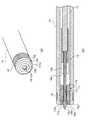
図1(a)、図1(b)は、それぞれ、本発明の一実施形態に係る内視鏡用高周波処置具1の構成を示す外観図、断面図である。概説すると、図1に示されるように、内視鏡用高周波処置具1は、高周波ナイフ12、高周波ナイフ12に接続されたワイヤ13、ナイフ12及びワイヤ13が挿通されたシース15、ワイヤ13及びシース15を操作するための操作部20等を備えており、シース15が不図示の内視鏡の処置具挿通チャンネルから体腔内に挿入されてESDの手技に使用される。 FIG. 1A and FIG. 1B are an external view and a cross-sectional view, respectively, showing the configuration of an endoscope high-
高周波ナイフ12は、SUS等のロッド状(例示的には丸棒状)の金属製部材であり、体腔内組織の切開・剥離処理等のため、高周波電流が通電される。高周波ナイフ12は、操作部20の操作によって進退されることにより、シース15の先端面からの突出量が変化するように構成されている。 The high-
図2及び図3は、内視鏡用高周波処置具1の先端部近傍の構成を示す拡大図である。図2(a)、図2(b)は、それぞれ、操作部20によって高周波ナイフ12を所定の前進位置(ナイフ前進位置)に移動させたときの状態を示す拡大斜視図、拡大断面図である。図3(a)、図3(b)は、それぞれ、操作部20によって高周波ナイフ12を所定の後退位置(ナイフ後退位置)に移動させたときの状態を示す拡大斜視図、拡大断面図である。 2 and 3 are enlarged views showing the configuration in the vicinity of the distal end portion of the endoscope high-
図2及び図3に示されるように、高周波ナイフ12は、その先端面(ナイフ先端面12a)近傍に、高周波ナイフ12の側面から突出する突起部材12bが設けられている。高周波ナイフ12は、その基端部が接続部材14を介してワイヤ13に電気的及び機械的に接続されている。 As shown in FIGS. 2 and 3, the high-
突起部材12bは、中心部分に貫通孔を有する錐状の金属製部材である。突起部材12bの先端側は、先細り形状となっており、具体的には、図2及び図3に示されるように、放物線テーパ形状となっている。また、突起部材12bの基端側は、フラットな基端面を持つ形状となっている。 The protruding
突起部材12bは、高周波ナイフ12がその貫通孔に挿通されて、ナイフ先端面12aから所定量後退した位置(例えばナイフ先端面12aから0.5mm後方の位置)で溶接されている。これにより、突起部材12bの先端側では、高周波ナイフ12と突起部材12bとが段差無く(高周波ナイフ12の側面と突起部材12bの放射線テーパ形状面とが鈍角をなして)接続され、突起部材12bの基端側では、高周波ナイフ12と突起部材12bとが段差をなして(高周波ナイフ12の側面と突起部材12bの基端面とが直角をなして)接続される。なお、高周波ナイフ12の外径は、高周波電流の密度を高めるため、約0.3mmと極力細く形成されている。また、突起部材12bの外径(最外径)は、約0.6mmに形成されている。 The protruding
本発明の一実施形態では、高周波ナイフ12と突起部材12bが別々の部材で構成されているが、別の実施形態では、高周波ナイフ12と突起部材12bが一体の部材で形成されてもよい。 In one embodiment of the present invention, the high-
ワイヤ13は、SUS等の金属製ワイヤである。ワイヤ13は、その先端が接続部材14によって高周波ナイフ12の基端と接続された状態でシース15に挿通されている。ワイヤ13の基端は、操作部20まで延びている。術者が操作部20を操作してシース15内でワイヤ13を進退させることにより、高周波ナイフ12がワイヤ13と一体となって進退して、シース15の先端面(シース先端面15a)に対する高周波ナイフ12の突出量が変化する。 The
接続部材14は、高周波ナイフ12及びワイヤ13の外径よりも大きく、且つシース15の内径よりも小さな外径を有する円筒状の金属製部材である。接続部材14の中心には、高周波ナイフ12の長手方向に沿って延びる貫通孔が形成されている。接続部材14の貫通孔は、先端側(高周波ナイフ12側)の径が高周波ナイフ12の外径よりも僅かに大きくなっており、また、基端側(ワイヤ13側)の径がワイヤ13の外径よりも僅かに大きくなっている。高周波ナイフ12、ワイヤ13は、それぞれ、接続部材14の貫通孔の先端側、基端側から挿入された後、ロー付けやレーザ溶接等によって接続部材14に固定されている。 The
図4は、図2のA−A断面図である。図2〜図4に示されるように、接続部材14には、その先端面(接続部材先端面14a)から基端側に延びる断面十字形状のスリット14bが形成されている。スリット14bは、シース15内に液体が注入されたときにシース先端面15aに液体を供給するための送水チャンネルの一部として機能する。 4 is a cross-sectional view taken along line AA in FIG. As shown in FIGS. 2 to 4, the connecting
シース15は、PTFE(polytetrafluoroethylene)等の樹脂からなる絶縁性及び可撓性を有する管状部材である。シース15は、体腔内に対する内視鏡用高周波処置具1の進入の度合いについて内視鏡による視認性を向上させるため、シース先端面15a近傍の外周面に周方向に亘ってマーカ16が設けられている。 The
シース先端面15aの外周端部(エッジ部)は、手技中のシース15の動作によって体腔内の粘膜が傷つくことの無いように面取りされている(面取り部15bが形成されている。)。 The outer peripheral end portion (edge portion) of the sheath
シース先端面15a近傍には、SUS等の金属製のストッパ17が固定されている。具体的には、ストッパ17は、シース15の内径と略同一の外径を有する円筒状部材であり、その外周面に抜け止め突起が形成されている。ストッパ17は、シース先端面15aからシース15内に圧入されてシース15の内面と嵌合し、ストッパ17の先端面(ストッパ先端面17a)がシース先端面15aと略同一面となる位置で固定されている。 A
ストッパ17には、高周波ナイフ12の外径よりも大きく、突起部材12bの外径よりも小さな径を有する貫通孔17cが高周波ナイフ12の長手方向(進退方向)に沿って形成されている。貫通孔17cには、高周波ナイフ12が挿通されている。また、ストッパ17のストッパ先端面17a側には、突起部材12bを収容する突起部材収容部17dが形成されている。 A through
図2に示されるように、操作部20を操作して高周波ナイフ12をワイヤ13と共に前進させると、接続部材先端面14aがストッパ17の基端面(ストッパ基端面17b)に当接する。これにより、高周波ナイフ12の突出量が規制され(高周波ナイフ12がナイフ前進位置で停止し)、高周波ナイフ12が必要以上にシース先端面15aから突出することはない。 As shown in FIG. 2, when the high-
図2に示されるように、高周波ナイフ12をナイフ前進位置まで前進させると、高周波ナイフ12の突出量が最大となる。本発明の一実施形態では、高周波ナイフ12の最大突出量が2mmに設定されている。高周波ナイフ12をナイフ前進位置まで前進させた状態で高周波ナイフ12に高周波電流を通電することにより、体腔内粘膜の切開・剥離処置を行うことができる。 As shown in FIG. 2, when the high-
また、シース15内に液体(例えば、薬液や生理食塩水等の洗浄水)が供給されると、スリット14bを通して、貫通孔17c(ストッパ17と高周波ナイフ12との間の隙間)に液体が供給されて、シース先端面15aから外部に噴射される。すなわち、貫通孔17cは、シース先端面15aから外部に液体を噴射させるための送水チャンネルの一部として機能する。 Further, when a liquid (for example, cleaning water such as a chemical solution or physiological saline) is supplied into the
図3に示されるように、操作部20を操作して高周波ナイフ2をワイヤ13と共に後退させると、突起部材12bが突起部材収容部17dに収容されて、突起部材12bの基端面が突起部材収容部17dを規定する壁部に当接し、突起部材12bが停止する。これにより、高周波ナイフ12とストッパ17とが電気的に接続されると共に、高周波ナイフ12の位置が規制され(高周波ナイフ12がナイフ後退位置で停止し)、突起部材12bの最も先端がストッパ先端面17aと略同一面上の位置となる。すなわち、ナイフ後退位置では、高周波ナイフ12の先端部分がシース先端面15a(言い換えると、ストッパ先端面17a)から0.5mmだけ突出した状態となる。 As shown in FIG. 3, when the operating
なお、ストッパ17は、高周波ナイフ12の位置に拘わらず、高周波ナイフ12と摺動可能に常に接触していてもよい。すなわち、ストッパ17は、高周波ナイフ12がナイフ前進位置以外の位置にあっても通電されるように構成されていてもよい。 The
ストッパ先端面17aの露出面積は、高周波ナイフ12や突起部材12bの外形と比べて遥かに大きい。そのため、突起部材12bを突起部材収容部17dに収容した状態で、高周波ナイフ12及びストッパ17に高周波電流を通電することにより、広い面積を焼灼することができ、具体的には、マーキング処置及び止血処置を行うことができる。 The exposed area of the
図1に示されるように、操作部20は、シース15が固定された本体22と、ワイヤ13の基端が固定されたスライダ24を備えている。本体22は、棒状部材であり、スライダ24を摺動させるためのガイド溝22aが軸方向に延設されている。本体22の基端側には、操作時に指を掛けるためのリング22bが設けられている。また、本体22の先端側には、シース15をガイドし、折れを防止する折れ止めチューブ30が設けられている。 As shown in FIG. 1, the
スライダ24は、本体22の外周を取り囲む筒状部24aと、操作時に指を掛けるハンドル24bを有している。また、スライダ24には、図示しない高周波電源と接続されるプラグ26が取付けられている。ワイヤ13の基端部は、筒状部24aの内部で、ネジ26aによってプラグ26と接続固定されている。 The
すなわち、スライダ24及びワイヤ13は、ガイド溝22aに沿って、高周波ナイフ12及びワイヤ13の長手方向に摺動可能に本体22に装着されている。従って、術者が内視鏡用高周波処置具1のスライダ24をリング22b側に移動させると、高周波ナイフ12が後退して、突起部材12bが突起部材収容部17dに収容され(図3参照)、内視鏡用高周波処置具1のスライダ24をシース先端面15a側に移動させると、高周波ナイフ12が前進する(図2参照)。また、高周波電源から通電される高周波電流は、導電性のプラグ26、ワイヤ13、接続部材14を介して高周波ナイフ12に供給される。 That is, the
折れ止めチューブ30の基端側(本体22側)には、液体注入口32が設けられている。不図示のシリンジや給水装置等が液体注入口32と接続されて、薬液や洗浄水等の液体が液体注入口32に注入されることにより、シース15内に液体が供給される。 A
シース15内に供給された液体は、シース15内を通りシース先端面15a側に送られて、接続部材14に形成されたスリット14b、貫通孔17c(ストッパ17と高周波ナイフ12との間の隙間)に供給される。高周波ナイフ12をナイフ後退位置(図3参照)から突出させると、貫通孔17cの先端が開放されるため、シース先端面15aから液体が噴射される。シース先端面15aから噴射される液体は、体腔内粘膜の切開・剥離処置中の高周波ナイフ12の洗浄や局注処置の局注液として用いられる。 The liquid supplied into the
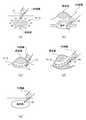
次に、本発明の一実施形態に係る内視鏡用高周波処置具1を用いたESDの手技について説明する。図5は、内視鏡用高周波処置具1を用いて行われるESDの各処置を説明する図である。 Next, an ESD procedure using the endoscope high-
[マーキング]
図5(a)は、本発明の一実施形態に係る内視鏡用高周波処置具1を用いて行われるマーキング処置を説明する図である。マーキング処置は、内視鏡の先端部を患者の体腔内に挿入し、ESDの切開対象となる病変部周辺に切開範囲の目印を付す工程である。[marking]
Fig.5 (a) is a figure explaining the marking process performed using the high
術者は、内視鏡の先端部を患者の体腔内に挿入した状態で、内視鏡の処置具挿通チャンネルにシース15を挿通し、内視鏡先端部からシース15を突出させる。術者は、内視鏡画像によってシース先端面15aと病変部の位置を確認しながら、高周波ナイフ12をナイフ後退位置(図3参照)まで後退させた状態で、シース先端面15aを病変部周辺の粘膜に押し当て、高周波ナイフ12に高周波電流を通電する。 The operator inserts the
ナイフ後退位置では、高周波ナイフ12に供給される高周波電流がストッパ17にも供給される。そのため、主に、ストッパ先端面17aの露出部分と接触した粘膜が焼灼されてマーキング痕が形成される。 At the knife retracted position, the high frequency current supplied to the
なお、ナイフ後退位置では、高周波ナイフ12の先端部分がシース先端面15aから0.5mm突出している。従って、シース先端面15aが病変部周辺の粘膜に押し当てられると、高周波ナイフ12が粘膜内に僅かに差し込まれる。これにより、高周波ナイフ12が粘膜表面で滑らないため、術者は、狙った位置にマーキング痕を形成することができる。 At the knife retracted position, the tip portion of the high-
術者は、上記の作業を複数回繰り返して、病変部の外縁を把握できる程度の個数のマーキング痕を形成し、マーキング処置を終了する。 The surgeon repeats the above operation a plurality of times to form marking marks as many as the outer edge of the lesioned part can be grasped, and ends the marking procedure.
なお、マーキング処置中、シース先端面15aが粘膜に押し当てられた状態で高周波ナイフ12に高周波電流が通電されると、高周波電流が通電される被通電部材のうち粘膜と接触する部分(主に、ストッパ先端面17a)に、例えば、焼灼によって熱凝固したヘモグロビンや蛋白質等の付着物が付着する可能性がある。 When a high-frequency current is applied to the high-
そこで、内視鏡用高周波処置具1は、ESDの処置中に粘膜に押し当てられる可能性のある部材の表面に、焦げ付き防止用の防汚コーティングが施されている。具体的には、内視鏡用高周波処置具1は、高周波ナイフ12、突起部材12b及びストッパ17のうち外観に現れる主な表面領域に、防汚コーティングが施されている。コーティング法としては、例えば、スピンコート法、ディップコート法、スプレーコート法等が挙げられる。 Accordingly, the endoscope high-
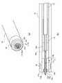
図9(a)、図9(b)は、それぞれ、高周波ナイフ12をナイフ前進位置に移動させたときの、内視鏡用高周波処置具1の先端部近傍の構成を示す拡大斜視図、拡大断面図である。図9において、ハッチングで示される領域が、防汚コーティングが施されている表面領域である。なお、図9(及び後述の図10)においては、防汚コーティングが施されている表面領域を明示する都合上、この表面領域以外(例え断面であっても)にハッチングを用いない。 9 (a) and 9 (b) are an enlarged perspective view and an enlarged view showing the configuration in the vicinity of the distal end portion of the endoscope high-
防汚コーティングの材料には、例えば、体腔内組織が焼灼によって炭化したときに発生するカーボンとの親和性が低いものが使用される。例示的には、フッ素化合物(テフロン(登録商標))や酸化ケイ素化合物(シリカ)、有機ケイ素化合物(シリコーン)等が使用される。 As the material for the antifouling coating, for example, a material having a low affinity with carbon generated when tissue in the body cavity is carbonized by cauterization is used. Illustratively, a fluorine compound (Teflon (registered trademark)), a silicon oxide compound (silica), an organosilicon compound (silicone), or the like is used.
図9に示される領域に防汚コーティングを施すことにより、マーキング処置中、蛋白質等の付着物が内視鏡用高周波処置具1に付着し難くなる。これにより、付着物によって処置が阻害され難くなるため、術者は、適切な処置を行いやすくなる。また、シース先端面15aから噴射される洗浄水によって除去し切れなかった付着物については、シース15を内視鏡から抜去して洗浄する必要がある。防汚コーティングによって付着物が付着し難くなることにより、この作業の回数が減るため、手技時間が短縮される。 By applying the antifouling coating to the region shown in FIG. 9, during the marking treatment, it becomes difficult for deposits such as proteins to adhere to the endoscope high-
なお、防汚コーティングは、高周波ナイフ12、突起部材12b、ストッパ17の全ての部材の表面領域に施されていなくてもよい。粘膜との接触面積が広い高周波ナイフ12とストッパ17のうち外観に現れる少なくとも一部の表面領域(その中でも特にストッパ先端面17a)に防汚コーティングが施されていれば、付着物の付着抑制の効果が得られる。 Note that the antifouling coating may not be applied to the surface regions of all members of the high-
[局注]
図5(b)は、本発明の一実施形態に係る内視鏡用高周波処置具1を用いて行われる局注処置を説明する図である。局注処置は、切開対象となる病変部の粘膜下層に液体を局所注射して、切開対象である病変部の粘膜を浮き上がらせる工程である。[Local note]
FIG.5 (b) is a figure explaining the local injection treatment performed using the high
術者は、内視鏡画像によってシース先端面15aと病変部の位置を確認しながら、高周波ナイフ12をナイフ前進位置(図2参照)まで前進させた状態で高周波電流を通電させ、シース先端面15aを粘膜下層に差し込むための孔を穿つ。術者は、次いで、高周波ナイフ12をナイフ後退位置(図3参照)まで後退させた状態で、シース先端面15aを粘膜下層に差し込む。術者は、シース先端面15aを粘膜下層に差し込むと、液体注入口32から薬液を注入し、この状態でスライダ24を操作して、高周波ナイフ12を僅かに前進させる。 While confirming the position of the sheath
[切開]
図5(c)は、本発明の一実施形態に係る内視鏡用高周波処置具1を用いて行われる切開処置を説明する図である。切開処置は、切開対象となる病変部の周囲をマーキング痕に沿って切開する工程である。[Incision]
FIG.5 (c) is a figure explaining the incision treatment performed using the endoscope high
術者は、内視鏡画像によってシース先端面15aとマーキング痕の位置を確認しながら、高周波ナイフ12をナイフ前進位置(図2参照)まで前進させ、高周波電流を通電させた状態で、シース先端面15aをマーキング痕に沿って移動させて全周切開を行う。 The surgeon advances the high-
図11(b)は、本発明の一実施形態に係る内視鏡用高周波処置具1を用いて粘膜病変部の周囲を切開している状態を示す図である。図11(b)に示されるように、突起部材12bは、基端面が高周波ナイフ12の側面と直交し、段差をなしている。この段差が粘膜内に嵌まり込み、一種の抜け止めとして機能する。そのため、切開中(ナイフ先端面12aを粘膜内に埋没させた状態で移動させている間)、ナイフ先端面12aが不用意に粘膜から抜けることがない。 FIG. 11B is a diagram showing a state in which the periphery of the mucosal lesion is incised using the endoscope high-
また、図11(b)に示されるように、突起部材12bの先端側は、高周波ナイフ12と段差無く(高周波ナイフ12の側面と突起部材12bの放射線テーパ形状面とが鈍角をなして)接続されている。そのため、切開中、高周波ナイフ12の側面と突起部材12bの放射線テーパ形状面との境界付近まで粘膜が接触する。そのため、シース先端面15aから突出する高周波ナイフ12の突出部分の全長(2mm)の深さの粘膜が切開される。すなわち、本発明の一実施形態によれば、高周波ナイフ12の全長を長くすることなく必要な深さ(ここでは2mm)を切開することができる。そのため、粘膜穿孔等の発生が防がれると共に切開の回数が抑えられ、延いては、手技の長時間化が抑えられる。 Further, as shown in FIG. 11B, the tip side of the protruding
切開処置では、出血を伴うことが多い。出血した場合、術者は、後述の止血処置を行う。また、切開処置では、粘膜や血液等が高周波ナイフ12に付着することにより、ナイフとしての機能が低下することがある。この場合、術者は、高周波ナイフ12を一旦粘膜から引き抜き、液体注入口32から液体を注入してナイフ先端面12aを洗浄する。すなわち、本発明の一実施形態によれば、内視鏡用高周波処置具1を取り出すことなくナイフ先端面12aを洗浄することが可能であり、また、止血処置を行うことが可能である。 Incision procedures are often accompanied by bleeding. In the case of bleeding, the surgeon performs the hemostasis treatment described below. In the incision procedure, mucous membranes, blood, and the like adhere to the high-
局注・切開処置中も、防汚コーティングにより、蛋白質等の付着物が内視鏡用高周波処置具1に付着し難い。局注・切開処置中は、主に、高周波ナイフ12や突起部材12bが粘膜と接触する。高周波ナイフ12や突起部材12bに付着物が付着した場合であっても、これらの部材には、洗浄水を直接噴射させやすい。そのため、局注・切開処置中、付着物に対しては、洗浄水による除去が有効である。 Even during the local injection / incision treatment, due to the antifouling coating, deposits such as proteins are unlikely to adhere to the endoscope high-
なお、高周波ナイフ12に施されている防汚コーティングの厚みは、ストッパ17に施されている防汚コーティングの厚みよりも薄い。高周波ナイフ12に対するコート厚を薄くすることにより、ナイフ前進位置における高周波ナイフ12の突出部分の全長(2mm)への影響(すなわち、コート厚の分だけ全長が長くなってしまうこと)が抑えられる。これは、粘膜穿孔等の発生を防ぐ観点から好適である。 In addition, the thickness of the antifouling coating applied to the
[剥離]
図5(d)は、本発明の一実施形態に係る内視鏡用高周波処置具1を用いて行われる剥離処置を説明する図である。剥離処置は、切開した病変部を少しずつ剥ぎ取る工程である。[Peeling]
FIG.5 (d) is a figure explaining the peeling treatment performed using the high
術者は、高周波ナイフ12をナイフ前進位置(図2参照)まで前進させ、高周波電流を通電させた状態で、切開した病変部を持ち上げながら、切開した病変部の粘膜下層を焼灼して剥離していく。剥離処置中も切開処置中と同様に、突起部材12bが粘膜内に適度に引っ掛かる。そのため、高周波ナイフ12が滑って粘膜から不用意に抜けることがない。 The surgeon advances the high-
剥離置中も、防汚コーティングにより、蛋白質等の付着物が内視鏡用高周波処置具1に付着し難い。剥離処置中も、局注・切開処置中と同様に、主に、高周波ナイフ12や突起部材12bが粘膜と接触する。そのため、付着物に対しては、洗浄水による除去が有効である。 Even during peeling, due to the antifouling coating, it is difficult for deposits such as proteins to adhere to the endoscope high-
[止血]
図5(e)は、本発明の一実施形態に係る内視鏡用高周波処置具1を用いて行われる止血処置を説明する図である。止血処置は、病変部を剥離した後の潰瘍部や切開、剥離処置中に出血した出血箇所を焼灼して止血する処理である。[Hemostasis]
FIG. 5 (e) is a diagram illustrating hemostasis treatment performed using the endoscope high-
術者は、高周波ナイフ12をナイフ後退位置(図3参照)まで後退させた状態で、シース先端面15aを出血した潰瘍部や粘膜に押し当て、高周波ナイフ12に高周波電流を通電して焼灼する。マーキング処置と同様に、ナイフ後退位置では、高周波ナイフ12に供給される高周波電流がストッパ17にも供給される。そのため、ストッパ先端面17aの露出部分と接触した比較的広い面積の粘膜が一度に焼灼されて止血処置される。 The surgeon presses the sheath
また、ナイフ後退位置では、高周波ナイフ12の先端部分がシース先端面15aから0.5mm突出している。従って、シース先端面15aが病変部周辺の粘膜に押し当てられると、高周波ナイフ12が粘膜内に僅かに差し込まれる。これにより、高周波ナイフ12が粘膜表面で滑らないため、術者は、狙った位置を的確に止血することができる。 Further, at the knife retracted position, the distal end portion of the high-
止血処置中も、防汚コーティングにより、蛋白質等の付着物が内視鏡用高周波処置具1に付着し難い。そのため、付着物によって処置が阻害され難くなり、術者は、適切な処置を行いやすくなる。 Even during the hemostatic treatment, due to the antifouling coating, deposits such as proteins hardly adhere to the endoscope high-
術者は、必要に応じて上述の動作(処置)を継続し、最終的に、病変部を一括切除し、鉗子を有する他の処置具等を用いて切除後の粘膜を回収し、ESDの手技を終了する。 The surgeon continues the above operation (procedure) as necessary, finally excision of the lesion part at once, collects the mucous membrane after excision using another treatment tool having forceps, etc. End the procedure.
以上が本発明の例示的な実施形態の説明である。本発明の実施形態は、上記に説明したものに限定されず、本発明の技術的思想の範囲において様々な変形が可能である。例えば明細書中に例示的に明示される実施形態等又は自明な実施形態等を適宜組み合わせた内容も本発明の実施形態に含まれる。例えば、上記の実施形態では、突起部材12bは、ナイフ先端面12aから0.5mm基端側に設けられているが、本発明はこれに限らない。別の実施形態では、突起部材12bは、ナイフ先端面12aから0.3mm〜0.7mmの範囲内に設けられていてもよい。 The above is the description of the exemplary embodiments of the present invention. Embodiments of the present invention are not limited to those described above, and various modifications are possible within the scope of the technical idea of the present invention. For example, the embodiment of the present invention also includes contents appropriately combined with embodiments or the like clearly shown in the specification or obvious embodiments. For example, in the above-described embodiment, the protruding
また、上記の実施形態では、突起部材12bの先端側の先細り形状として放射線テーパ形状を例示したが、本発明はこれに限らない。図6〜図8に、他の先細り形状を持つ突起部材12bの側面図を示す。図6に示されるように、突起部材12bは、線形テーパ状の先細り形状を持つ錐状部材であってもよい。また、図7、図8のそれぞれに示されるように、突起部材12bは、円盤状部材であり、先端面側がR面取り、C面取りされることにより、実質的に先細りに形成されたものであってもよい。 Moreover, in said embodiment, although the radiation taper shape was illustrated as a taper shape at the front end side of the
また、突起部材12bの先細り形状は、放射線テーパ形状や線形テーパ形状、面取りされた形状に限らない。例示的には、突起部材12bの先細り形状は、指数関数テーパ形状や他の関数によって定義可能な形状であってもよく、また、このような関数に近似する形状であってもよい。 Further, the tapered shape of the protruding
また、図10に、別の実施形態に係る内視鏡用高周波処置具1の先端部近傍の構成を拡大図で示す。図10においては、高周波ナイフ12をナイフ後退位置に移動させた状態を示す。 Moreover, in FIG. 10, the structure of the front-end | tip part vicinity of the high
図10に示されるように、別の実施形態に係る突起部材12bは、円盤状に形成されている。高周波ナイフ12をナイフ後退位置に移動させると、突起部材収容部17dに収容された突起部材12bの先端面とストッパ先端面17aとが略同一面上に位置する。すなわち、別の実施形態では、マーキング処置及び止血処置中、粘膜との接触面積の広いストッパ先端面17aと略同一面上に、同じく粘膜との接触面積の広い突起部材12bの先端面が位置する。そのため、これらの面に対する付着物の付着が懸念される。そこで、別の実施形態では、図10中、ハッチングで示される表面領域に対して防汚コーティングが施されている。これにより、図10のような、粘膜との接触面積が広い構成であっても、付着物の付着が好適に抑えられる。 As FIG. 10 shows, the
1 内視鏡用高周波処置具
12 高周波ナイフ
12a ナイフ先端面
12b 突起部材
13 ワイヤ
14 接続部材
14a 接続部材先端面
14b スリット
15 シース
15a シース先端面
15b 面取り
16 マーカ
17 ストッパ
17a ストッパ先端面
17b ストッパ基端面
17c 貫通孔
17d 突起部材収容部
20 操作部
22 本体
22a ガイド溝
22b リング
24 スライダ
24a 筒状部
24b ハンドル
26 プラグ
26a ネジ
30 折れ止めチューブ
32 液体注入口DESCRIPTION OF
Claims (5)
Translated fromJapanese前記可撓性シースの先端に嵌入された導電性を持つ先端部材と、
前記可撓性シース内部に挿通された導電性を持つワイヤと、
前記ワイヤの先端に接続されており、操作部によって該ワイヤが前記可撓性シース内で進退されることにより、前記可撓性シースの先端面からの突出量が変化する、導電性を持つロッド状のナイフ部と、
前記ワイヤを介して前記先端部材及び前記ナイフ部に高周波電流を流すための高周波電源を接続可能な接点部と、
を備え、
前記ナイフ部は、
前記ナイフ部の最も先端から所定量後退した位置に、該ナイフ部の側面から突出する突起部材が設けられており、
前記ワイヤと共に後退されると、前記突起部材が前記先端部材に当接して、前記ナイフ部の先端部分が該先端部材の先端面から所定量突出した位置で停止し、
前記突起部材は、
先端側が先細り形状となっている、
内視鏡用高周波処置具。A flexible sheath that can be inserted into a treatment instrument insertion channel of an endoscope;
A conductive tip member inserted into the tip of the flexible sheath;
A conductive wire inserted through the flexible sheath;
A conductive rod that is connected to the tip of the wire, and that changes in the amount of protrusion from the tip of the flexible sheath when the wire is advanced and retracted in the flexible sheath by the operating portion. A knife-shaped part,
A contact part capable of connecting a high-frequency power source for flowing a high-frequency current to the tip member and the knife part via the wire;
With
The knife portion is
A protruding member protruding from the side surface of the knife part is provided at a position retracted by a predetermined amount from the most distal end of the knife part,
When retracted together with the wire, the protruding member comes into contact with the tip member and stops at a position where the tip portion of the knife portion protrudes from the tip surface of the tip member by a predetermined amount,
The protruding member is
The tip side is tapered,
High-frequency treatment tool for endoscope.
先端側がテーパ形状又は面取りされた形状となっている、
請求項1に記載の内視鏡用高周波処置具。The protruding member is
The tip side is tapered or chamfered,
The high-frequency treatment tool for endoscope according to claim 1.
基端側が前記ナイフ部の側面に対して段差をなす形状を持つ、
請求項1又は請求項2に記載の内視鏡用高周波処置具。The protruding member is
The base end side has a shape forming a step with respect to the side surface of the knife part,
The high-frequency treatment instrument for endoscope according to claim 1 or 2.
前記先端部材の先端側に前記突起部材を収容する収容部
を有し、
前記ナイフ部が前記ワイヤと共に後退されると、前記突起部材が前記収容部内に収容されて該収容部を規定する壁部に当接して停止すると共に、該ナイフ部の先端部分が前記先端部材の先端面から所定量突出した位置で停止する、
請求項1から請求項3の何れか一項に記載の内視鏡用高周波処置具。The tip member is
A housing portion for housing the protruding member on the distal end side of the distal member;
When the knife portion is retracted together with the wire, the projecting member is accommodated in the accommodating portion and comes into contact with a wall portion defining the accommodating portion and stops, and the tip portion of the knife portion is Stop at a position protruding a predetermined amount from the tip surface,
The high-frequency treatment instrument for an endoscope according to any one of claims 1 to 3.
0.3mm〜0.7mmの範囲内である、
請求項1から請求項4の何れか一項に記載の内視鏡用高周波処置具。The predetermined amount is
Within a range of 0.3 mm to 0.7 mm,
The high-frequency treatment tool for endoscopes according to any one of claims 1 to 4.
Priority Applications (3)
| Application Number | Priority Date | Filing Date | Title |
|---|---|---|---|
| JP2016004573AJP6655398B2 (en) | 2016-01-13 | 2016-01-13 | High frequency treatment tool for endoscope |
| CN201790000013.6UCN207666692U (en) | 2016-01-13 | 2017-01-10 | Endoscope-use high-frequency treatment instrument |
| PCT/JP2017/000395WO2017122607A1 (en) | 2016-01-13 | 2017-01-10 | High-frequency treatment device for endoscope |
Applications Claiming Priority (1)
| Application Number | Priority Date | Filing Date | Title |
|---|---|---|---|
| JP2016004573AJP6655398B2 (en) | 2016-01-13 | 2016-01-13 | High frequency treatment tool for endoscope |
Publications (2)
| Publication Number | Publication Date |
|---|---|
| JP2017123995Atrue JP2017123995A (en) | 2017-07-20 |
| JP6655398B2 JP6655398B2 (en) | 2020-02-26 |
Family
ID=59312084
Family Applications (1)
| Application Number | Title | Priority Date | Filing Date |
|---|---|---|---|
| JP2016004573AActiveJP6655398B2 (en) | 2016-01-13 | 2016-01-13 | High frequency treatment tool for endoscope |
Country Status (3)
| Country | Link |
|---|---|
| JP (1) | JP6655398B2 (en) |
| CN (1) | CN207666692U (en) |
| WO (1) | WO2017122607A1 (en) |
Cited By (1)
| Publication number | Priority date | Publication date | Assignee | Title |
|---|---|---|---|---|
| US12108975B2 (en) | 2018-04-23 | 2024-10-08 | Micro-Tech (Nanjing) Co., Ltd. | Multifunctional high-frequency electric knife |
Families Citing this family (1)
| Publication number | Priority date | Publication date | Assignee | Title |
|---|---|---|---|---|
| JP2023067784A (en)* | 2021-10-29 | 2023-05-16 | オリンパスメディカルシステムズ株式会社 | Endoscopic treatment tool |
Citations (10)
| Publication number | Priority date | Publication date | Assignee | Title |
|---|---|---|---|---|
| JPS6250610U (en)* | 1985-09-17 | 1987-03-28 | ||
| JP2005270240A (en)* | 2004-03-24 | 2005-10-06 | Pentax Corp | Endoscopic treatment tool for endoscope |
| JP2005279126A (en)* | 2004-03-31 | 2005-10-13 | Pentax Corp | Endoscopic treatment tool for endoscope |
| JP2007044393A (en)* | 2005-08-12 | 2007-02-22 | Fujinon Corp | High-frequency treatment instrument |
| JP2008272204A (en)* | 2007-04-27 | 2008-11-13 | Naohisa Yahagi | Endoscopic treatment tool |
| JP2008272365A (en)* | 2007-05-07 | 2008-11-13 | Olympus Medical Systems Corp | Endoscopic treatment tool |
| JP2009090003A (en)* | 2007-10-11 | 2009-04-30 | Fujinon Corp | High-frequency treatment instrument for endoscope |
| JP2010035668A (en)* | 2008-08-01 | 2010-02-18 | Hoya Corp | Treatment tool for endoscope |
| JP2010213946A (en)* | 2009-03-18 | 2010-09-30 | Fujifilm Corp | High frequency treatment instrument |
| JP2013111308A (en)* | 2011-11-30 | 2013-06-10 | Hoya Corp | High frequency treatment instrument for endoscope |
- 2016
- 2016-01-13JPJP2016004573Apatent/JP6655398B2/enactiveActive
- 2017
- 2017-01-10CNCN201790000013.6Upatent/CN207666692U/enactiveActive
- 2017-01-10WOPCT/JP2017/000395patent/WO2017122607A1/ennot_activeCeased
Patent Citations (10)
| Publication number | Priority date | Publication date | Assignee | Title |
|---|---|---|---|---|
| JPS6250610U (en)* | 1985-09-17 | 1987-03-28 | ||
| JP2005270240A (en)* | 2004-03-24 | 2005-10-06 | Pentax Corp | Endoscopic treatment tool for endoscope |
| JP2005279126A (en)* | 2004-03-31 | 2005-10-13 | Pentax Corp | Endoscopic treatment tool for endoscope |
| JP2007044393A (en)* | 2005-08-12 | 2007-02-22 | Fujinon Corp | High-frequency treatment instrument |
| JP2008272204A (en)* | 2007-04-27 | 2008-11-13 | Naohisa Yahagi | Endoscopic treatment tool |
| JP2008272365A (en)* | 2007-05-07 | 2008-11-13 | Olympus Medical Systems Corp | Endoscopic treatment tool |
| JP2009090003A (en)* | 2007-10-11 | 2009-04-30 | Fujinon Corp | High-frequency treatment instrument for endoscope |
| JP2010035668A (en)* | 2008-08-01 | 2010-02-18 | Hoya Corp | Treatment tool for endoscope |
| JP2010213946A (en)* | 2009-03-18 | 2010-09-30 | Fujifilm Corp | High frequency treatment instrument |
| JP2013111308A (en)* | 2011-11-30 | 2013-06-10 | Hoya Corp | High frequency treatment instrument for endoscope |
Cited By (1)
| Publication number | Priority date | Publication date | Assignee | Title |
|---|---|---|---|---|
| US12108975B2 (en) | 2018-04-23 | 2024-10-08 | Micro-Tech (Nanjing) Co., Ltd. | Multifunctional high-frequency electric knife |
Also Published As
| Publication number | Publication date |
|---|---|
| WO2017122607A1 (en) | 2017-07-20 |
| JP6655398B2 (en) | 2020-02-26 |
| CN207666692U (en) | 2018-07-31 |
Similar Documents
| Publication | Publication Date | Title |
|---|---|---|
| JP5755121B2 (en) | Endoscopic high-frequency treatment instrument | |
| JP5415727B2 (en) | Endoscopic treatment tool | |
| KR100595803B1 (en) | High-frequency knife and endoscopic apparatus | |
| JP4109092B2 (en) | High frequency knife | |
| KR101099912B1 (en) | High frequency knife | |
| US9610120B2 (en) | High-frequency treatment tool for endoscope | |
| JP4870710B2 (en) | High frequency knife and high frequency knife system | |
| CN100528095C (en) | High-frequency treatment tool | |
| US20140207134A1 (en) | High-frequency knife | |
| JPH08299355A (en) | High frequency knife | |
| JP2008029667A (en) | High-frequency treatment instrument | |
| WO2016029201A1 (en) | Attachment for electrosurgical system | |
| CN115068100B (en) | Endoscopic surgical tool | |
| CN108523986B (en) | High-frequency cutter with injection needle for endoscope | |
| CN111658128A (en) | Multifunctional high-frequency cutter | |
| JP2010213946A (en) | High frequency treatment instrument | |
| JP2023067784A (en) | Endoscopic treatment tool | |
| CN206809326U (en) | High-frequency processing tools for endoscopes | |
| JP4965416B2 (en) | High frequency treatment tool | |
| JP2009090003A (en) | High-frequency treatment instrument for endoscope | |
| JP6655398B2 (en) | High frequency treatment tool for endoscope | |
| US9168095B2 (en) | High-frequency treatment device | |
| CN206007354U (en) | Endoscope-use scalpel | |
| JP7497515B2 (en) | Endoscopic treatment tools | |
| KR20150106671A (en) | High-frequency treatment device formed insulation |
Legal Events
| Date | Code | Title | Description |
|---|---|---|---|
| RD04 | Notification of resignation of power of attorney | Free format text:JAPANESE INTERMEDIATE CODE: A7424 Effective date:20170718 | |
| A621 | Written request for application examination | Free format text:JAPANESE INTERMEDIATE CODE: A621 Effective date:20181228 | |
| A131 | Notification of reasons for refusal | Free format text:JAPANESE INTERMEDIATE CODE: A131 Effective date:20191017 | |
| A521 | Request for written amendment filed | Free format text:JAPANESE INTERMEDIATE CODE: A523 Effective date:20191205 | |
| TRDD | Decision of grant or rejection written | ||
| A01 | Written decision to grant a patent or to grant a registration (utility model) | Free format text:JAPANESE INTERMEDIATE CODE: A01 Effective date:20200114 | |
| A61 | First payment of annual fees (during grant procedure) | Free format text:JAPANESE INTERMEDIATE CODE: A61 Effective date:20200203 | |
| R150 | Certificate of patent or registration of utility model | Ref document number:6655398 Country of ref document:JP Free format text:JAPANESE INTERMEDIATE CODE: R150 | |
| R250 | Receipt of annual fees | Free format text:JAPANESE INTERMEDIATE CODE: R250 | |
| R250 | Receipt of annual fees | Free format text:JAPANESE INTERMEDIATE CODE: R250 | |
| R250 | Receipt of annual fees | Free format text:JAPANESE INTERMEDIATE CODE: R250 |