JP2017116682A - Projection device - Google Patents
Projection deviceDownload PDFInfo
- Publication number
- JP2017116682A JP2017116682AJP2015250857AJP2015250857AJP2017116682AJP 2017116682 AJP2017116682 AJP 2017116682AJP 2015250857 AJP2015250857 AJP 2015250857AJP 2015250857 AJP2015250857 AJP 2015250857AJP 2017116682 AJP2017116682 AJP 2017116682A
- Authority
- JP
- Japan
- Prior art keywords
- light
- light source
- diffusion plate
- microlens array
- plate
- Prior art date
- Legal status (The legal status is an assumption and is not a legal conclusion. Google has not performed a legal analysis and makes no representation as to the accuracy of the status listed.)
- Pending
Links
Images


Classifications
- G—PHYSICS
- G03—PHOTOGRAPHY; CINEMATOGRAPHY; ANALOGOUS TECHNIQUES USING WAVES OTHER THAN OPTICAL WAVES; ELECTROGRAPHY; HOLOGRAPHY
- G03B—APPARATUS OR ARRANGEMENTS FOR TAKING PHOTOGRAPHS OR FOR PROJECTING OR VIEWING THEM; APPARATUS OR ARRANGEMENTS EMPLOYING ANALOGOUS TECHNIQUES USING WAVES OTHER THAN OPTICAL WAVES; ACCESSORIES THEREFOR
- G03B21/00—Projectors or projection-type viewers; Accessories therefor
- G03B21/14—Details
- G03B21/20—Lamp housings
- G03B21/208—Homogenising, shaping of the illumination light
- G—PHYSICS
- G02—OPTICS
- G02B—OPTICAL ELEMENTS, SYSTEMS OR APPARATUS
- G02B27/00—Optical systems or apparatus not provided for by any of the groups G02B1/00 - G02B26/00, G02B30/00
- G02B27/10—Beam splitting or combining systems
- G02B27/14—Beam splitting or combining systems operating by reflection only
- G02B27/141—Beam splitting or combining systems operating by reflection only using dichroic mirrors
- G—PHYSICS
- G02—OPTICS
- G02B—OPTICAL ELEMENTS, SYSTEMS OR APPARATUS
- G02B27/00—Optical systems or apparatus not provided for by any of the groups G02B1/00 - G02B26/00, G02B30/00
- G02B27/10—Beam splitting or combining systems
- G02B27/14—Beam splitting or combining systems operating by reflection only
- G02B27/145—Beam splitting or combining systems operating by reflection only having sequential partially reflecting surfaces
- G—PHYSICS
- G02—OPTICS
- G02B—OPTICAL ELEMENTS, SYSTEMS OR APPARATUS
- G02B3/00—Simple or compound lenses
- G02B3/0006—Arrays
- G—PHYSICS
- G02—OPTICS
- G02B—OPTICAL ELEMENTS, SYSTEMS OR APPARATUS
- G02B5/00—Optical elements other than lenses
- G02B5/02—Diffusing elements; Afocal elements
- G02B5/0273—Diffusing elements; Afocal elements characterized by the use
- G02B5/0278—Diffusing elements; Afocal elements characterized by the use used in transmission
- G—PHYSICS
- G03—PHOTOGRAPHY; CINEMATOGRAPHY; ANALOGOUS TECHNIQUES USING WAVES OTHER THAN OPTICAL WAVES; ELECTROGRAPHY; HOLOGRAPHY
- G03B—APPARATUS OR ARRANGEMENTS FOR TAKING PHOTOGRAPHS OR FOR PROJECTING OR VIEWING THEM; APPARATUS OR ARRANGEMENTS EMPLOYING ANALOGOUS TECHNIQUES USING WAVES OTHER THAN OPTICAL WAVES; ACCESSORIES THEREFOR
- G03B21/00—Projectors or projection-type viewers; Accessories therefor
- G03B21/14—Details
- G03B21/20—Lamp housings
- G03B21/2006—Lamp housings characterised by the light source
- G03B21/2033—LED or laser light sources
Landscapes
- Physics & Mathematics (AREA)
- General Physics & Mathematics (AREA)
- Optics & Photonics (AREA)
- Projection Apparatus (AREA)
- Transforming Electric Information Into Light Information (AREA)
Abstract
Translated fromJapaneseDescription
Translated fromJapanese本発明は、投影装置に関する。 The present invention relates to a projection apparatus.
今日、パーソナルコンピュータの画面やビデオ画像、更にメモリカード等に記憶されている画像データによる画像等をスクリーンに投影する画像投影装置としてのデータプロジェクタが多用されている。このプロジェクタは、光源から射出された光をDMD(デジタル・マイクロミラー・デバイス)や液晶板などの表示素子に集光させ、スクリーン上にカラー画像を表示する。 2. Description of the Related Art Today, data projectors are widely used as image projection apparatuses that project a screen of a personal computer, a video image, an image based on image data stored in a memory card or the like onto a screen. This projector condenses light emitted from a light source on a display element such as a DMD (digital micromirror device) or a liquid crystal plate, and displays a color image on a screen.
このデータプロジェクタでは、例えばレーザ光源から射出されたレーザ光は、コリメータレンズを透過し拡散板で広がりマイクロレンズアレイに入射される。レーザ光は、拡散板によりマイクロレンズアレイに広く当たるように入射される。その後、レーザ光は集光レンズにより集光され、プリズムを介して表示素子へ照射される。表示素子で形成された画像光は、投影光学系よりスクリーンに投影される。 In this data projector, for example, laser light emitted from a laser light source passes through a collimator lens, spreads by a diffusion plate, and enters a microlens array. The laser light is incident so as to widely hit the microlens array by the diffusion plate. Thereafter, the laser light is condensed by a condenser lens and irradiated to the display element through a prism. Image light formed by the display element is projected onto the screen by the projection optical system.
特許文献1には、レーザ光を拡散板により拡散させた後、集光レンズにより集光させて表示素子に照射するプロジェクタが開示されている。また、特許文献1には、拡散板を透過した光をインテグレータ光学系とする複数のレンズを有するレンズアレイを透過させて集光レンズにより集光することも開示されている。この構成によれば、光源装置から射出されたコヒーレント光は拡散板により拡散され、インテグレータ光学系としたレンズアレイにより均一な照度分布の光束とされて表示素子に照射することができる。 Patent Document 1 discloses a projector that irradiates a display element by diffusing laser light with a diffusion plate and then condensing the laser light with a condenser lens. Patent Document 1 also discloses that light transmitted through a diffuser plate is transmitted through a lens array having a plurality of lenses using an integrator optical system and condensed by a condensing lens. According to this configuration, the coherent light emitted from the light source device is diffused by the diffusion plate, and can be irradiated to the display element as a light flux having a uniform illuminance distribution by the lens array as the integrator optical system.
また、特許文献2には、光源ユニットが、所定波長帯域光を射出する励起光源と、表面を反射面とし、励起光源からの射出光を励起光として所定波長帯域光を射出する蛍光体層が敷設された蛍光発光部、及び、励起光源からの射出光を拡散反射させる拡散部、を有した発光板と、を備えるプロジェクタが開示されている。発光板と励起光源との間には、TIRプリズム(Total Internal Reflection Prism)が配置され、発光板からの光は、TIRプリズムを通りマイクロレンズアレイ、集光レンズ及びRTIRプリズム(Reverse Total Internal Reflection Prism)を介して表示素子に照射され、表示素子からのオン光は、再度RTIRプリズムに入射されて投影光学系を介してスクリーンに投影される。 Further, in Patent Document 2, a light source unit includes an excitation light source that emits light of a predetermined wavelength band, and a phosphor layer that emits light of a predetermined wavelength band using a surface as a reflection surface and light emitted from the excitation light source as excitation light. A projector is disclosed that includes a fluorescent plate that is laid and a light-emitting plate that has a diffuser that diffuses and reflects light emitted from an excitation light source. A TIR prism (Total Internal Reflection Prism) is disposed between the light-emitting plate and the excitation light source, and light from the light-emitting plate passes through the TIR prism, a microlens array, a condenser lens, and an RTIR prism (Reverse Total Internal Reflection Prism). ), And the ON light from the display element is incident on the RTIR prism again and projected onto the screen via the projection optical system.
しかし、従来技術や特許文献1,2に開示された技術は、レーザ光がマイクロレンズアレイに楕円形の断面形状で入射し、入射範囲が少ない場合、投影画面は左右で輝度バランスが悪くなり、中央は明るいけれど隅が暗くなり、またマイクロレンズアレイによる回折の影響で格子状の模様が現れてしまうという問題があった。 However, in the prior art and the techniques disclosed in Patent Documents 1 and 2, when the laser light is incident on the microlens array with an elliptical cross-sectional shape and the incident range is small, the luminance balance on the left and right of the projection screen becomes poor, Although the center is bright, the corners are dark, and there is a problem that a lattice-like pattern appears due to the influence of diffraction by the microlens array.
本発明の目的は、マイクロレンズアレイの出射側に拡散板を配置することにより、投影画面上の照度の分布や格子模様を拡散して均一にすることができる光源装置と、この光源装置を備える投影装置を提供する。 An object of the present invention is to provide a light source device capable of diffusing and uniforming the illuminance distribution and the lattice pattern on the projection screen by disposing a diffusion plate on the emission side of the microlens array, and the light source device. A projection device is provided.
本発明に係る投影装置は、レーザ発光素子による光源と、前記光源からの出射光が入射される第1の拡散板と、前記第1の拡散板を透過した光が入射されるマイクロレンズアレイと、前記マイクロレンズアレイを透過した光を拡散させる第2の拡散板と、を有することを特徴とする。 A projection apparatus according to the present invention includes a light source using a laser light emitting element, a first diffuser plate on which light emitted from the light source is incident, and a microlens array on which light transmitted through the first diffuser plate is incident. And a second diffusing plate for diffusing the light transmitted through the microlens array.
本発明によれば、マイクロレンズアレイの出射側に拡散板を配置することにより、投影画面上の照度の分布や格子模様を拡散して均一にすることができる。 According to the present invention, by arranging the diffusion plate on the emission side of the microlens array, the illuminance distribution and the lattice pattern on the projection screen can be diffused and made uniform.
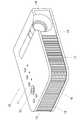
以下、本発明の実施形態を図に基づいて説明する。図1は、投影装置10の外観斜視図である。なお、本実施形態において、投影装置10における左右とは投影方向に対しての左右方向を示し、前後とは投影装置10のスクリーン側方向及び光線束の進行方向に対しての前後方向を示す。 Hereinafter, embodiments of the present invention will be described with reference to the drawings. FIG. 1 is an external perspective view of the
そして、投影装置10の筐体は、図1に示すように、略直方体形状であって、正面板12、背面板13、左側板14及び右側板15からなる側面板と、上面板11と下面板16とにより形成されている。投影装置10は、正面板12の左側方に投影部を有する。さらに、正面板12には、複数の吸排気孔17が設けられている。そして、投影装置10は、図示しないが、リモートコントローラからの制御信号を受信するIr受信部を備えている。 As shown in FIG. 1, the housing of the
また、上面板11にはキー/インジケータ部37が設けられる。このキー/インジケータ部37には、電源スイッチキーや電源のオン又はオフを報知するパワーインジケータ、投影のオン、オフを切りかえる投影スイッチキー、光源装置や表示素子又は制御回路等が過熱したときに報知をする過熱インジケータ等のキーやインジケータが配置されている。 The
さらに、背面板13には、図示しないUSB端子やアナログRGB映像信号が入力される映像信号入力用のD−SUB端子、S端子、RCA端子、音声出力端子等を設ける入出力コネクタ部及び電源アダプタプラグ等の各種端子が設けられている。また、背面板13には、複数の吸気孔が形成されている。 Further, the
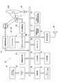
次に、投影装置10の投影装置制御手段とする投影装置制御部について図2の機能ブロック図を用いて述べる。投影装置制御部は、制御部38、入出力インターフェース22、画像変換部23、表示エンコーダ24、表示駆動部26等から構成される。 Next, a projection device control unit serving as a projection device control unit of the
この制御部38は、投影装置10内の各回路の動作制御を司るものであって、CPU、各種セッティング等の動作プログラムを固定的に記憶したROM及びワークメモリとして使用されるRAM等により構成されている。 The
そして、この投影装置制御部により、入出力コネクタ部21から入力された各種規格の画像信号は、入出力インターフェース22、システムバス(SB)を介して画像変換部23で表示に適した所定のフォーマットの画像信号に統一するように変換された後、表示エンコーダ24に出力される。 The image signal of various standards input from the input /
また、表示エンコーダ24は、入力された画像信号をビデオRAM25に展開記憶させた上でこのビデオRAM25の記憶内容からビデオ信号を生成して表示駆動部26に出力する。 The
表示駆動部26は、表示素子制御手段として機能するものであり、表示エンコーダ24から出力された画像信号に対応して適宜フレームレートで空間的光変調素子(SOM)である表示素子51を駆動するものである。そして、この投影装置10は、光源装置60から出射された光線束を、光源側光学系を介して表示素子51に照射することにより、表示素子51の反射光で光像(画像光)を形成し、投影側光学系を介して図示しないスクリーンに画像を投影表示する。なお、この投影側光学系の可動レンズ群は、レンズモータ45によりズーム調整やフォーカス調整のための駆動が行われる。 The
また、画像圧縮/伸長部31は、画像信号の輝度信号及び色差信号をADCT及びハフマン符号化等の処理によりデータ圧縮して着脱自在な記録媒体とされるメモリカード32に順次書き込む記録処理を行う。 The image compression /
さらに、画像圧縮/伸長部31は、再生モード時にメモリカード32に記録された画像データを読み出し、一連の動画を構成する個々の画像データを1フレーム単位で伸長し、この画像データを、画像変換部23を介して表示エンコーダ24に出力し、メモリカード32に記憶された画像データに基づいて動画等の表示を可能とする処理を行う。 Further, the image compression /
そして、筐体の上面板11に設けられるメインキー及びインジケータ等により構成されるキー/インジケータ部37の操作信号は、直接に制御部38に送出され、リモートコントローラからのキー操作信号は、Ir受信部35で受信され、Ir処理部36で復調されたコード信号が制御部38に出力される。 Then, the operation signal of the key /
なお、制御部38にはシステムバス(SB)を介して音声処理部47が接続されている。この音声処理部47は、PCM音源等の音源回路を備えており、投影モード及び再生モード時には音声データをアナログ化し、スピーカ48を駆動して拡声放音させる。 Note that an
また、制御部38は、光源制御手段としての光源制御回路41を制御しており、この光源制御回路41は、画像生成時に要求される所定波長帯域の光が光源装置60から出射されるように、光源装置60の赤色、緑色及び青色の波長帯域光を発光させる個別の制御を行う。 Further, the
さらに、制御部38は、冷却ファン駆動制御回路43に光源装置60等に設けた複数の温度センサによる温度検出を行わせ、この温度検出の結果から冷却ファンの回転速度を制御させている。また、制御部38は、冷却ファン駆動制御回路43にタイマー等により投影装置本体の電源オフ後も冷却ファンの回転を持続させる、あるいは、温度センサによる温度検出の結果によっては投影装置10本体の電源をオフにする等の制御も行う。 Further, the
次に、この投影装置10の内部構造について述べる。図3は、投影装置10の内部構造を示す平面模式図である。投影装置10は、図3に示すように、中央部分に光源装置60としての光源ユニットを備え、光源ユニットの左側方に投影光学系が内装されたレンズ鏡筒225を備えている。また、投影装置10は、レンズ鏡筒225と背面板13との間に、左側板14と平行に配置されたDMD等の表示素子51を備えている。さらに、投影装置10は、光源ユニットと正面板12との間に主制御回路基板241を備え、レンズ鏡筒225と左側板14との間に電源制御回路基板242を備えている。 Next, the internal structure of the
また、投影装置10は、光源ユニットに集光レンズ172を備え、光源ユニットの出射光を集光レンズ172により集光してRTIRプリズム175を介して表示素子51に照射し、かつ、表示素子51で反射されたオン光の光軸を、RTIRプリズム175により投影光学系の光軸に一致させて投影光学系に向かって出射する。 In addition, the
集光レンズ172とRTIRプリズム175との間には、第2の拡散板302が設置され、第2の拡散板302は集光レンズ172を透過した光を拡散して表示素子51に照射できる。第2の拡散板302の拡散角度は、第1の拡散板301の拡散角度よりも小さくなっている。 A
また、光源ユニットと右側板15との間には、背面板13側から順に、電源コネクタ57、後述する青色光源141用のヒートシンク190、後述する赤色光源121及び蛍光板101で発生する熱をヒートシンク190へ導くヒートパイプ130、冷却ファン261を備えている。 Further, between the light source unit and the
光源ユニットは、マイクロレンズアレイ151の右側であって投影装置10の中央近傍に配置された励起光照射装置70及び冷却ファン261の近傍であって投影装置10の中央近傍に配置された蛍光発光装置100による緑色光源装置と、蛍光発光装置100の隣に配置された赤色光源装置120と、電源コネクタ57の近傍であって背面板13の近傍に配置された青色光源装置140と、を備えている。 The light source unit is located on the right side of the
励起光照射装置70は、背面板13の中央近傍に設置され、光軸が左側板14と平行とされて正面板12の方向に光を出射する励起光源71と、励起光源71の光軸上に配置されたコリメータレンズ73と、を備える。この励起光源71は、青色レーザ発光器であり、励起光照射装置70の前方に配置される第1のダイクロイックミラー155を介して蛍光発光装置100に向けて青色波長帯域のレーザ光を出射する。 The excitation
尚、コリメータレンズ73は、励起光源71からの出射光を略平行な光線束として僅かに拡散させるように照射する。また、励起光源71は、励起光源71と背面板13との間に設置されたヒートシンク80と接触しており、このヒートシンク80によって冷却される。 The
そして、蛍光発光装置100は、蛍光板101と蛍光板101の後方に配置される集光レンズ110を備える。蛍光板101は、表面が鏡面加工された方形状の平板であって、正面板12と平行に配置され、この鏡面上に方形状の緑色蛍光体層が敷設されている。この緑色蛍光体層は、耐熱性及び透光性の高いシリコン樹脂等のバインダと、このバインダに均一に散りばめられた緑色蛍光体と、から形成されている。 The fluorescent
この鏡面加工された平板の上に蛍光体層が敷設された蛍光板101は、励起光源71から出射されたレーザ光線を励起光とし、蛍光体層の蛍光体から緑色波長帯域の蛍光光を励起光の入射面と同一の面から出射する。また、この蛍光板101の緑色蛍光体層は、表示素子51と相似形状とされており、緑色蛍光体層から出射される光線束の断面形状は、表示素子51の形状に近似したものとなる。 The
赤色光源装置120は、光軸が右側板15と平行とされた赤色光源121と赤色光源121の光軸上に配置された集光レンズ125を備える。この赤色光源121は、赤色発光ダイオードであり、赤色光源121から出射される光は集光レンズ125により所定の拡散範囲に制限された光束とされて赤色光源装置120から出射されるものであり、赤色光源121はヒートシンク190によって冷却される。 The red
青色光源装置140は、光軸が背面板13と平行とされた青色光源141と青色光源141の光軸上に配置されたコリメータレンズ145を備える。この青色光源141は、青色レーザダイオードであり、青色光源141から出射される光はコリメータレンズ145により所定の拡散範囲に制限された光束とされて青色光源141から出射されるものであり、青色光源141はヒートシンク190によって冷却される。 The blue
コリメータレンズ145と第1のダイクロイックミラー155との間には、第1の拡散板301が設置され、第1の拡散板301は光を拡散してマイクロレンズアレイ151に出射する。 A
光源ユニットの光源光学系は、第1の拡散板301と第1のダイクロイックミラー155と第2のダイクロイックミラー161とマイクロレンズアレイ151と集光レンズ172と第2の拡散板302とを有している。第2の拡散板302は、マイクロレンズアレイ151と表示素子51との間に設けられており、第2の拡散板302は、マイクロレンズアレイ151よりも表示素子51側に位置するように配置されている。 The light source optical system of the light source unit includes a
第1の拡散板301は青色光源装置140から出射される光線束の光軸上に配置され、青色光源装置140から出射される青色波長帯域光を拡散させて、第1のダイクロイックミラー155と第2のダイクロイックミラー161を介してマイクロレンズアレイ151に青色波長帯域光を照射する。 The
第1のダイクロイックミラー155は、青色光源装置140から出射される光線束の光軸と赤色光源装置120から出射される光線束の光軸とが交わる位置に設置され、赤色光源装置120からの出射光を背面板13と平行として左側板14の方向に反射する。第2のダイクロイックミラー161は、青色光源装置140から出射される光線束の光軸と蛍光発光装置100から出射される光線束の光軸とが交わる位置に設置され、蛍光発光装置100からの出射光を背面板13と平行として左側板14の方向に向けて反射する。マイクロレンズアレイ151は、蛍光発光装置100、赤色光源装置120、青色光源装置140からの出射光を透過させる。 The first
この第1のダイクロイックミラー155は、赤色波長帯域光を反射し、青色波長帯域光を透過させる。また、第2のダイクロイックミラー161は、緑色波長帯域光を反射し、赤色波長帯域光や青色波長帯域光を透過させる。 The first
そして、青色光源装置140から出射されるレーザ光の青色波長帯域光は、第1の拡散板301、第1のダイクロイックミラー155、第2のダイクロイックミラー161及びマイクロレンズアレイ151を透過して集光レンズ172に入射される。 Then, the blue wavelength band light of the laser light emitted from the blue
また、赤色光源装置120から出射される非コヒーレントな光である赤色波長帯域光は、第1のダイクロイックミラー155により反射され、第2のダイクロイックミラー161及びマイクロレンズアレイ151を透過して集光レンズ172に入射される。 The red wavelength band light, which is non-coherent light emitted from the red
また、蛍光発光装置100から出射される非コヒーレントな光である緑色波長帯域光は、第2のダイクロイックミラー161で反射されて青色波長帯域光及び赤色波長帯域光の光軸と同一の光軸とされ、マイクロレンズアレイ151を透過して集光レンズ172に入射される。 Further, the green wavelength band light that is incoherent light emitted from the fluorescent
このように、マイクロレンズアレイ151を透過した各原色光は、集光レンズ172に入射され、集光レンズ172によりマイクロレンズアレイ151の各マイクロ凸レンズの像を重ねるように表示素子51の画像形成面に照射され、光密度の均一な光線束とされて第2の拡散板302を介して表示素子51に入射されることになる。 In this way, each primary color light transmitted through the
図4は、本発明の実施形態に係る投影装置の光学系を示す概略図である。青色光源装置140の青色光源141からのレーザ光はコリメータレンズ145を透過し、出射される。コリメータレンズ145のレーザ光進行方向に第1の拡散板301が設置され、レーザ光は第1の拡散板301で広がり、第1のダイクロイックミラー155と第2のダイクロイックミラー161とを透過し、マイクロレンズアレイ151に入射する。 FIG. 4 is a schematic diagram showing an optical system of the projection apparatus according to the embodiment of the present invention. The laser light from the blue
第1の拡散板301は、表面に出射する光の拡散角度を小さくするための微小な凹凸が形成されている。第1の拡散板301から出射する光の出射角を小さくすることにより、出射光が余り広がらないように抑制できる。第1の拡散板301の表面にはサイズの微小な凹凸が、完全にランダムな状態で形成されている。この微小な凹凸が設計通りの拡散角で透過光を屈折させる。第1の拡散板301は表面の凹凸が小さい場合、拡散角度が小さくなり、表面の凹凸が大きい場合、拡散角度が大きくなると共に、第1の拡散板301を透過することによりコヒーレント光は、そのコヒーレント性が低下され、または非コヒーレント化される。 The
また、赤色光源装置120の赤色光源121から出射された非コヒーレント光の赤色波長帯域光は、第1のダイクロイックミラー155で反射され、マイクロレンズアレイ151に入射される。 Further, the non-coherent red wavelength band light emitted from the
励起光照射装置70の励起光源71から出射された励起光は、第2のダイクロイックミラー161と集光レンズ110とを透過し、蛍光板101に照射される。蛍光板101で発光された非コヒーレント光の緑色波長帯域光は、第2のダイクロイックミラー161で反射され、マイクロレンズアレイ151に入射される。 Excitation light emitted from the
マイクロレンズアレイ151を透過した光は、集光レンズ172を透過後、RTIRプリズム175の入射前に画質改善用の第2の拡散板302を透過する。 The light transmitted through the
これにより、光の照度分布は均一に、または格子模様は拡散されてから表示素子51へ照射される。表示素子51に入射した光は、表示素子51の有効範囲とほぼ同一の範囲を照射している。表示素子51に入射した光は、表示素子51で反射され、矢印に示す方向にRTIRプリズム175で反射して投影レンズ側へ導かれる。 As a result, the light illuminance distribution is uniform or the lattice pattern is diffused before being applied to the
図5は、本発明の実施形態に係る表示素子51の有効範囲311に対する照射範囲312を示す図である。表示素子51の有効範囲311は長方形の範囲であり、照射範囲312は有効範囲311より少し大きい長方形の範囲である。有効範囲311の外側の照射範囲312はロスになるが、その面積が小さいので、投影画面での影響が小さい。 FIG. 5 is a diagram showing an
また、図4に示したマイクロレンズアレイ151と集光レンズ172との距離を変更するように集光レンズ172を移動させて調整することにより、集光レンズ172による透過光の焦点位置を変更することができるので、光が第2の拡散板302を透過しても有効範囲に近い範囲のみに照射させることができる。 Further, the focal position of the transmitted light by the
そして、集光レンズ172の位置と第2の拡散板302との位置を逆にしてもよい。もっとも、集光レンズ172で集光した光を第2の拡散板302に入射するように集光レンズ172をマイクロレンズアレイ151側に配置すれば、マイクロレンズアレイ151を透過した光線束の広がりを少なくして光源装置60の光学系を容易に小型化することができる。 The position of the
また、本実施の形態では、レーザ光を第1の拡散板301と第2の拡散板302とで拡散して表示素子51の全体に光源光を照射するため、第2の拡散板302を用いない場合に比較して第1の拡散板301の拡散率を小さくすることができる。 In the present embodiment, the
また、例えば、赤色光源装置120として赤色レーザダイオードを用いることもある。この場合、第1の拡散板301を第1のダイクロイックミラー155と第2のダイクロイックミラー161との間に配置し、赤色光源装置120からのレーザ光も第1の拡散板301を透過させ、マイクロレンズアレイ151に入射させる。 For example, a red laser diode may be used as the red
更に、励起光光源と蛍光発光装置100とを緑色レーザダイオードに変えることもある。この場合は、第2のダイクロイックミラー161とマイクロレンズアレイ151との間に第1の拡散板301を配置し、青色波長帯域光と共に緑色波長帯域光も第1の拡散板301を透過させ、マイクロレンズアレイ151に入射させる。 Further, the excitation light source and the fluorescent
以上のように、マイクロレンズアレイ151と表示素子51との間に、光を拡散する第2の拡散板302が設置されたことにより、投影画面上の照度の分布や格子模様を拡散して均一にすることができる光源装置60と、この光源装置60を備える投影装置10を提供することができる。 As described above, the
また、マイクロレンズアレイ151の入射側に、光軸合成器としての第1のダイクロイックミラー155と第2のダイクロイックミラー161とを有することにより、青色のレーザ光と異なる色の光をマイクロレンズアレイ151に入射し、異なる色の光を出射する光源装置を有する投影装置とすることができる。 Further, by having a first
また、第1のダイクロイックミラー155と第2のダイクロイックミラー161との2枚が配置されることにより、青色のレーザ光の他に赤色と緑色の光を入射し、三原色を出射する光源装置を有する投影装置とすることができる。 Further, by providing two sheets of the first
また、第1の拡散板301及び第2の拡散板302は、表面に微小な凹凸を有することにより、レーザ光を第1の拡散板301と第2の拡散板302とで拡散して表示素子51の全体に均一な光源光を照射することができる。また、第2の拡散板302を用いない場合に比較して第1の拡散板301の拡散率を小さくすることができる。ただし、第1の拡散板301の表面に形成される凹凸は、第2の拡散板302の表面に形成される凹凸より大きくなっており、第1の拡散板301から出射する光の出射角は第2の拡散板302から出射する光の出射角よりも大きくなっている。 Further, the
また、集光レンズ172は、マイクロレンズアレイ151と第2の拡散板302との間に設置し、集光レンズ172で集光した光を第2の拡散板302に入射させるように集光レンズ172をマイクロレンズアレイ151側に配置すれば、マイクロレンズアレイ151を透過した光線束の広がりを少なくして第2の拡散板302に入射させ、投影装置における光源装置60の光学系を容易に小型化し、小型の投影装置とすることが容易にできる。 The condensing
また、以上説明した実施形態は、例として提示したものであり、発明の範囲を限定することは意図していない。これら新規な実施形態は、その他の様々な形態で実施されることが可能であり、発明の趣旨を逸脱しない範囲で、種々の省略、置き換え、変更を行うことができる。これらの実施形態やその変形は、発明の範囲や要旨に含まれるとともに、特許請求の範囲に記載された発明とその均等の範囲に含まれる。 Further, the embodiment described above is presented as an example, and is not intended to limit the scope of the invention. These novel embodiments can be implemented in various other forms, and various omissions, replacements, and changes can be made without departing from the spirit of the invention. These embodiments and modifications thereof are included in the scope and gist of the invention, and are included in the invention described in the claims and the equivalents thereof.
以下に、本願出願の最初の特許請求の範囲に記載された発明を付記する。
[1]レーザ発光素子による光源と、
前記光源からの出射光が入射される第1の拡散板と、
前記第1の拡散板を透過した光が入射されるマイクロレンズアレイと、
前記マイクロレンズアレイを透過した光を拡散させる第2の拡散板と、
を有することを特徴とする投影装置。
[2]更に画像光を生成する表示素子を有し、
前記第2の拡散板は、前記マイクロレンズアレイと前記表示素子との間に設けられており、
前記第2の拡散板は、前記マイクロレンズアレイよりも前記表示素子側に位置することを特徴とする前記[1]に記載の投影装置。
[3]前記第1の拡散板の拡散角度は、前記第2の拡散板の拡散角度よりも大きいことを特徴とする前記[1]又は前記[2]に記載の投影装置。
[4]前記マイクロレンズアレイの入射側に、光軸合成器としてのダイクロイックミラーを更に有することを特徴とする前記[1]乃至前記[3]の何れかに記載の光源装置。
[5]前記ダイクロイックミラーは、2枚が配置されることを特徴とする前記[4]に記載の投影装置。
[6]前記第1の拡散板及び前記第2の拡散板は、表面に微小な凹凸を有することを特徴とする前記[1]乃至前記[5]の何れかに記載の投影装置。
[7]前記集光レンズは、前記マイクロレンズアレイと前記第2の拡散板との間に設置されることを特徴とする前記[1]乃至前記[6]の何れかに記載の投影装置。
[8]前記表示素子から出射された画像光をスクリーンに投影する投影側光学系と、
前記光源装置や前記表示素子を制御する投影装置制御手段と、
を有することを特徴とする前記[1]乃至前記[7]の何れかに記載の投影装置。The invention described in the first claim of the present application will be appended below.
[1] a light source by a laser light emitting element;
A first diffusion plate on which light emitted from the light source is incident;
A microlens array on which light transmitted through the first diffusion plate is incident;
A second diffusion plate for diffusing the light transmitted through the microlens array;
A projection apparatus comprising:
[2] It further has a display element that generates image light,
The second diffusion plate is provided between the microlens array and the display element,
The projection apparatus according to [1], wherein the second diffusion plate is positioned closer to the display element than the microlens array.
[3] The projection apparatus according to [1] or [2], wherein a diffusion angle of the first diffusion plate is larger than a diffusion angle of the second diffusion plate.
[4] The light source device according to any one of [1] to [3], further including a dichroic mirror as an optical axis combiner on the incident side of the microlens array.
[5] The projection apparatus according to [4], wherein two dichroic mirrors are arranged.
[6] The projection device according to any one of [1] to [5], wherein the first diffusion plate and the second diffusion plate have minute irregularities on the surface.
[7] The projector according to any one of [1] to [6], wherein the condenser lens is installed between the microlens array and the second diffusion plate.
[8] A projection-side optical system that projects image light emitted from the display element onto a screen;
Projection device control means for controlling the light source device and the display element;
The projection apparatus according to any one of [1] to [7], including:
10 投影装置 11 上面板
12 正面板 13 背面板
14 右側板 15 左側板
16 下面板 17 吸排気孔
21 入出力コネクタ部 22 入出力インターフェース
23 画像変換部 24 表示エンコーダ
25 ビデオRAM 26 表示駆動部
31 画像圧縮/伸長部 32 メモリカード
35 Ir受信部 36 Ir処理部
37 キー/インジケータ部 38 制御部
41 光源制御回路 43 冷却ファン駆動制御回路
45 レンズモータ 47 音声処理部
48 スピーカ 51 表示素子
60 光源装置 70 励起光照射装置
71 青色レーザダイオード 73 コリメータレンズ
80 ヒートシンク 100 蛍光発光装置
101 蛍光板 110 集光レンズ
120 赤色光源装置 121 赤色光源
125 集光レンズ 130 ヒートパイプ
140 青色光源装置 141 青色光源
145 コリメータレンズ 151 マイクロレンズアレイ
155 第1のダイクロイックミラー 161 第2のダイクロイックミラー
172 集光レンズ 175 RTIRプリズム
190 ヒートシンク 225 固定レンズ群
241 制御回路基板 261 冷却ファン
301 第1の拡散板 302 第2の拡散板
311 有効範囲 312 照射範囲DESCRIPTION OF
Claims (8)
Translated fromJapanese前記光源からの出射光が入射される第1の拡散板と、
前記第1の拡散板を透過した光が入射されるマイクロレンズアレイと、
前記マイクロレンズアレイを透過した光を拡散させる第2の拡散板と、
を有することを特徴とする投影装置。A light source by a laser light emitting element;
A first diffusion plate on which light emitted from the light source is incident;
A microlens array on which light transmitted through the first diffusion plate is incident;
A second diffusion plate for diffusing the light transmitted through the microlens array;
A projection apparatus comprising:
前記第2の拡散板は、前記マイクロレンズアレイと前記表示素子との間に設けられており、
前記第2の拡散板は、前記マイクロレンズアレイよりも前記表示素子側に位置することを特徴とする請求項1に記載の投影装置。Furthermore, it has a display element that generates image light,
The second diffusion plate is provided between the microlens array and the display element,
The projection apparatus according to claim 1, wherein the second diffusion plate is located closer to the display element than the microlens array.
前記マイクロレンズアレイの入射側に、光軸合成器としてのダイクロイックミラーを更に有することを特徴とする請求項1乃至請求項3の何れかに記載の投影装置。The light transmitted through the microlens array passes through the condenser lens,
The projection apparatus according to claim 1, further comprising a dichroic mirror as an optical axis synthesizer on an incident side of the microlens array.
前記光源装置や前記表示素子を制御する投影装置制御手段と、
を有することを特徴とする請求項2に記載の投影装置。A projection-side optical system that projects image light emitted from the display element onto a screen;
Projection device control means for controlling the light source device and the display element;
The projection apparatus according to claim 2, further comprising:
Priority Applications (3)
| Application Number | Priority Date | Filing Date | Title |
|---|---|---|---|
| JP2015250857AJP2017116682A (en) | 2015-12-24 | 2015-12-24 | Projection device |
| US15/296,410US9971236B2 (en) | 2015-12-24 | 2016-10-18 | Projector having two diffusion plates |
| CN201611113723.8ACN106918979B (en) | 2015-12-24 | 2016-12-07 | Projection device |
Applications Claiming Priority (1)
| Application Number | Priority Date | Filing Date | Title |
|---|---|---|---|
| JP2015250857AJP2017116682A (en) | 2015-12-24 | 2015-12-24 | Projection device |
Publications (1)
| Publication Number | Publication Date |
|---|---|
| JP2017116682Atrue JP2017116682A (en) | 2017-06-29 |
Family
ID=59087180
Family Applications (1)
| Application Number | Title | Priority Date | Filing Date |
|---|---|---|---|
| JP2015250857APendingJP2017116682A (en) | 2015-12-24 | 2015-12-24 | Projection device |
Country Status (3)
| Country | Link |
|---|---|
| US (1) | US9971236B2 (en) |
| JP (1) | JP2017116682A (en) |
| CN (1) | CN106918979B (en) |
Families Citing this family (3)
| Publication number | Priority date | Publication date | Assignee | Title |
|---|---|---|---|---|
| JP6851029B2 (en)* | 2017-03-09 | 2021-03-31 | パナソニックIpマネジメント株式会社 | Projection light source device |
| CN108761973A (en)* | 2018-04-13 | 2018-11-06 | 郑州浩本科技有限公司 | Multifunctional projector |
| JP7463197B2 (en)* | 2020-06-11 | 2024-04-08 | 株式会社小糸製作所 | Image projection device and vehicle lighting fixture |
Citations (5)
| Publication number | Priority date | Publication date | Assignee | Title |
|---|---|---|---|---|
| JP2003098476A (en)* | 2001-08-27 | 2003-04-03 | Eastman Kodak Co | Laser projection display system |
| JP2010256573A (en)* | 2009-04-23 | 2010-11-11 | Olympus Corp | Projection type display |
| JP2014032371A (en)* | 2012-08-06 | 2014-02-20 | Oxide Corp | Speckle contrast generator and speckle contrast evaluation device |
| WO2014199485A1 (en)* | 2013-06-13 | 2014-12-18 | Necディスプレイソリューションズ株式会社 | Illumination optics, projector, and projector system |
| US20150286064A1 (en)* | 2014-04-08 | 2015-10-08 | Omnivision Technologies, Inc. | Reducing speckle in projected images |
Family Cites Families (3)
| Publication number | Priority date | Publication date | Assignee | Title |
|---|---|---|---|---|
| JP2001351425A (en)* | 2000-06-08 | 2001-12-21 | Fujitsu Ltd | Backlight device and liquid crystal display device |
| JP5534336B2 (en) | 2010-09-29 | 2014-06-25 | カシオ計算機株式会社 | Light source unit and projector |
| JP6318659B2 (en) | 2014-02-03 | 2018-05-09 | セイコーエプソン株式会社 | Lighting device and projector |
- 2015
- 2015-12-24JPJP2015250857Apatent/JP2017116682A/enactivePending
- 2016
- 2016-10-18USUS15/296,410patent/US9971236B2/enactiveActive
- 2016-12-07CNCN201611113723.8Apatent/CN106918979B/enactiveActive
Patent Citations (5)
| Publication number | Priority date | Publication date | Assignee | Title |
|---|---|---|---|---|
| JP2003098476A (en)* | 2001-08-27 | 2003-04-03 | Eastman Kodak Co | Laser projection display system |
| JP2010256573A (en)* | 2009-04-23 | 2010-11-11 | Olympus Corp | Projection type display |
| JP2014032371A (en)* | 2012-08-06 | 2014-02-20 | Oxide Corp | Speckle contrast generator and speckle contrast evaluation device |
| WO2014199485A1 (en)* | 2013-06-13 | 2014-12-18 | Necディスプレイソリューションズ株式会社 | Illumination optics, projector, and projector system |
| US20150286064A1 (en)* | 2014-04-08 | 2015-10-08 | Omnivision Technologies, Inc. | Reducing speckle in projected images |
Also Published As
| Publication number | Publication date |
|---|---|
| CN106918979A (en) | 2017-07-04 |
| US9971236B2 (en) | 2018-05-15 |
| US20170184952A1 (en) | 2017-06-29 |
| CN106918979B (en) | 2019-12-06 |
Similar Documents
| Publication | Publication Date | Title |
|---|---|---|
| JP6787261B2 (en) | Light source device and projection device | |
| JP6390922B2 (en) | Light source device and projection device | |
| JP6493739B2 (en) | Light source device and projection device | |
| JP5510732B2 (en) | Light source unit and projector | |
| JP6344596B2 (en) | Light source device and projection device | |
| JP6380813B2 (en) | Light source device and projection device | |
| JP2014062951A (en) | Light source device and projector | |
| JP2015166787A (en) | Light source device and projection device | |
| JP6402906B2 (en) | Light source device and projection device | |
| JP2013190591A (en) | Light source device and projector | |
| JP2017156619A (en) | Light source device and projection device | |
| JP2015038618A (en) | Light emitting unit and projector | |
| JP6425058B2 (en) | Light source device and projection device | |
| JP6938902B2 (en) | Light source device and projection device | |
| JP6820703B2 (en) | Light source device and projection device | |
| US9971236B2 (en) | Projector having two diffusion plates | |
| JP2014157361A (en) | Light source unit and projector | |
| JP6493721B2 (en) | Light source optical device and projector | |
| JP5618130B2 (en) | Light emitting unit and projector | |
| JP5812136B2 (en) | Illumination optical system, light source device and projector | |
| JP6701531B2 (en) | Light source device and projection device | |
| JP6270012B2 (en) | Light source device, lighting method of light source device, and projector | |
| JP2020160420A (en) | Electronic device, projection device, and cooling control method | |
| JP6332678B2 (en) | Light source device and projection device | |
| JP6432765B2 (en) | Light source device and projector |
Legal Events
| Date | Code | Title | Description |
|---|---|---|---|
| A131 | Notification of reasons for refusal | Free format text:JAPANESE INTERMEDIATE CODE: A131 Effective date:20170831 | |
| A521 | Request for written amendment filed | Free format text:JAPANESE INTERMEDIATE CODE: A523 Effective date:20171027 | |
| A02 | Decision of refusal | Free format text:JAPANESE INTERMEDIATE CODE: A02 Effective date:20180215 |