JP2017112973A - Combine - Google Patents
CombineDownload PDFInfo
- Publication number
- JP2017112973A JP2017112973AJP2015255294AJP2015255294AJP2017112973AJP 2017112973 AJP2017112973 AJP 2017112973AJP 2015255294 AJP2015255294 AJP 2015255294AJP 2015255294 AJP2015255294 AJP 2015255294AJP 2017112973 AJP2017112973 AJP 2017112973A
- Authority
- JP
- Japan
- Prior art keywords
- vertical
- grain
- frame
- posture
- conveyance unit
- Prior art date
- Legal status (The legal status is an assumption and is not a legal conclusion. Google has not performed a legal analysis and makes no representation as to the accuracy of the status listed.)
- Granted
Links
Images


Landscapes
- Threshing Machine Elements (AREA)
Abstract
Translated fromJapaneseDescription
Translated fromJapanese本発明は、コンバイン、詳しくは、刈取部によって刈取られた刈取穀稈を脱穀処理する脱穀装置と、前記脱穀装置によって得られた穀粒を貯留する穀粒タンクと、前記穀粒タンクに貯留された穀粒を機外へ排出する穀粒排出装置と、を備えたコンバインに関する。 The present invention relates to a combiner, more specifically, a threshing device for threshing a harvested cereal harvested by a reaping unit, a grain tank for storing the grain obtained by the threshing device, and the grain tank. The present invention relates to a combine equipped with a grain discharging device that discharges the dried grain to the outside of the machine.
上記したコンバインにおいて、穀粒タンクの下端部に接続されたL字形状の接続ケースが備えられ、穀粒排出装置に、接続ケースに接続されて上方向に延びる縦搬送部と、縦搬送部の上端部に接続されて横方向に延び、先端部に排出口を有する横搬送部と、を備え、穀粒排出装置は、縦搬送部の軸芯を旋回中心として、横搬送部が機体外側へ張り出す排出姿勢と、横搬送部が機体内側に格納されて穀粒タンクの上方に位置する格納姿勢とに亘り旋回可能であるものがある。これは、穀粒排出装置を排出姿勢にすることで、穀粒タンクの穀粒を、機体外に位置する運搬車の荷台などの供給先に排出することができ、穀粒排出装置を格納姿勢にすることで、横搬送部を機体内側に格納することができるものである。 In the above-described combine, an L-shaped connection case connected to the lower end of the grain tank is provided, the grain discharging device is connected to the connection case and extends upward, and the vertical transport unit And a horizontal transport unit that is connected to the upper end and extends in the horizontal direction and has a discharge port at the front end. There are some which can be swung between a protruding discharge posture and a storage posture in which the lateral conveyance unit is stored inside the machine body and located above the grain tank. This is because the kernel of the grain tank can be discharged to a supply destination such as a carrier bed located outside the fuselage by setting the grain discharging device to the discharging posture. By doing so, the lateral conveyance section can be stored inside the machine body.
この種のコンバインにおいて、従来、例えば特許文献1に示されるように、機体フレームに立設された縦フレームによって縦オーガ(縦搬送部に相当)が支持され、かつ、グレンタンクによって縦オーガが支持されるものがあった。特許文献1に示されるものでは、機体フレームに第1縦フレーム及び第2縦フレームが立設され、第1縦フレームと第2縦フレームとに亘って横フレームが架設され、第1縦フレームの上部に第1取付部材が設けられている。縦オーガの中間部を回動可能に保持する第2取付部材が第1取付部材に設けられている。また、縦オーガの上部を回動可能に保持する第3取付部材がグレンタンクに設けられている。 Conventionally, in this type of combine, a vertical auger (corresponding to a vertical transport unit) is supported by a vertical frame erected on a machine frame and a vertical auger is supported by a glen tank, as shown in
従来の支持構造を採用した場合、縦フレームを機体フレームに立設するので、縦フレームと縦搬送部とが離れがちとなり、縦フレームから張り出して縦搬送部をする支持部材の張り出し長さが長くなり、縦搬送部の揺れを抑制し難いなど、十分な支持効果を得難い。また、縦搬送部を一端側で支持する支持部材の他端側を穀粒タンクに連結するので、穀粒タンクに十分な補強を施す必要が生じがちである。 When the conventional support structure is adopted, the vertical frame is erected on the machine frame, so the vertical frame tends to be separated from the vertical conveyance unit, and the overhang length of the support member that protrudes from the vertical frame and forms the vertical conveyance unit is long. Therefore, it is difficult to obtain a sufficient support effect, such as it is difficult to suppress the shaking of the vertical conveyance unit. Moreover, since the other end side of the support member which supports a vertical conveyance part by one end side is connected with a grain tank, it is easy to arise that it is necessary to give sufficient reinforcement to a grain tank.
本発明は、縦搬送部をしっかり支持し易いコンバインを提供する。 The present invention provides a combine that is easy to firmly support a vertical conveyance unit.
本発明によるコンバインは、
刈取部によって刈取られた刈取穀稈を脱穀処理する脱穀装置と、前記脱穀装置によって得られた穀粒を貯留する穀粒タンクと、前記穀粒タンクに貯留された穀粒を機外へ排出する穀粒排出装置と、を備え、
前記穀粒タンクの下端部に接続されたL字形状の接続ケースが備えられ、
前記穀粒排出装置に、前記接続ケースに接続されて上方向に延びる縦搬送部と、前記縦搬送部の上端部に接続されて横方向に延び、先端部に排出口を有する横搬送部と、を備え、
前記穀粒排出装置は、前記縦搬送部の軸芯を旋回中心として、前記横搬送部が機体外側へ張り出す排出姿勢と、前記横搬送部が機体内側に格納されて前記穀粒タンクの上方に位置する格納姿勢とに亘り旋回可能であり、
前記縦搬送部に寄り添う状態で機体上下方向に沿って延び、前記縦搬送部を支持する縦フレームが備えられ、
前記縦フレームの下部が前記接続ケースに支持され、かつ、前記縦フレームの上部に前記縦搬送部が支持されている。The combine according to the present invention is:
A threshing device for threshing the harvested cereals harvested by the reaping unit, a grain tank for storing the grain obtained by the threshing device, and discharging the grain stored in the grain tank to the outside of the machine A grain discharging device,
An L-shaped connection case connected to the lower end of the grain tank is provided,
A vertical conveying unit connected to the connection case and extending upward in the grain discharging device, a horizontal conveying unit connected to the upper end of the vertical conveying unit and extending in the horizontal direction, and having a discharge port at the tip. With
The grain discharging device includes a discharging posture in which the horizontal conveying unit projects to the outside of the machine body with the axial center of the vertical conveying unit as a turning center, and the horizontal conveying unit is stored inside the machine body so as to be above the grain tank. Can be swung over the retracted position located at
A vertical frame is provided that extends along the vertical direction of the machine body in a state of snuggling up to the vertical conveyance unit and supports the vertical conveyance unit,
The lower part of the vertical frame is supported by the connection case, and the vertical transport unit is supported by the upper part of the vertical frame.
本構成によると、縦フレームが接続ケースに支持されるので、縦搬送部に近い箇所から縦搬送部を縦フレームによって支持させることができて、高い支持効果を得られる。穀粒タンクの下端部と縦搬送部とを接続すると共に縦搬送部を支持することで丈夫な接続ケースに縦フレームが支持されるので、縦フレームをしっかり支持させることができる。 According to this configuration, since the vertical frame is supported by the connection case, the vertical conveyance unit can be supported by the vertical frame from a location close to the vertical conveyance unit, and a high support effect can be obtained. Since the vertical frame is supported by the strong connection case by connecting the lower end portion of the grain tank and the vertical conveyance unit and supporting the vertical conveyance unit, the vertical frame can be firmly supported.
従って、縦搬送部の上端部から横方向に延びる横搬送部の荷重に抗して縦搬送部を縦フレームによってしっかり支持させることができ、穀粒排出装置をスムーズに旋回させることができる。また、供給先の上方に排出口を安定的に位置させることができて、穀粒を供給し易い。縦フレームによる縦搬送部の支持を縦搬送部に近い箇所から行わせられるので、縦フレームと縦搬送部とに亘る支持部材を小型にすることが可能になる。 Therefore, the vertical conveyance unit can be firmly supported by the vertical frame against the load of the horizontal conveyance unit extending in the horizontal direction from the upper end of the vertical conveyance unit, and the grain discharging device can be smoothly turned. Moreover, the outlet can be stably positioned above the supply destination, and it is easy to supply the grain. Since the vertical conveyance unit is supported by the vertical frame from a position close to the vertical conveyance unit, it is possible to reduce the size of the support member extending between the vertical frame and the vertical conveyance unit.
本発明においては、前記縦フレームは、第一縦フレームを備え、前記第一縦フレームは、前記縦搬送部に対して、前記穀粒排出装置が前記格納姿勢となったときの前記排出口とは反対側の位置に設けられていると好適である。 In the present invention, the vertical frame includes a first vertical frame, and the first vertical frame includes the discharge port when the grain discharge device is in the retracted position with respect to the vertical conveyance unit. Is preferably provided at the opposite position.
本構成によれば、穀粒排出装置が格納姿勢に旋回されると、横搬送部が機体内側に位置する延出状態で縦搬送部から延出し、この延出状態の横搬送部の荷重が縦搬送部に掛かる。このとき、第一縦フレームは、縦搬送部に対して排出口が位置する側と反対側、すなわち、横搬送部の延長線上に位置するので、第一縦フレームは横搬送部の荷重を効率良く受け止め、穀粒排出装置が横搬送部の荷重によって傾くことを効果的に防止できる。 According to this configuration, when the grain discharging device is turned to the retracted position, the horizontal conveyance unit extends from the vertical conveyance unit in the extended state positioned inside the machine body, and the load of the horizontal conveyance unit in the extended state is Hanging on the vertical transfer section. At this time, since the first vertical frame is located on the side opposite to the side where the discharge port is located with respect to the vertical conveyance unit, that is, on the extension line of the horizontal conveyance unit, the first vertical frame efficiently loads the load of the horizontal conveyance unit. It can be received well, and the grain discharging device can be effectively prevented from being tilted by the load of the lateral conveying section.
本発明においては、前記縦フレームは、第二縦フレームを備え、前記第二縦フレームは、前記縦搬送部に対して、前記穀粒排出装置が前記排出姿勢となったときの前記排出口とは反対側の位置に設けられていると好適である。 In this invention, the said vertical frame is equipped with the 2nd vertical frame, and the said 2nd vertical frame is the said discharge port when the said grain discharge apparatus becomes the said discharge attitude | position with respect to the said vertical conveyance part. Is preferably provided at the opposite position.
本構成によると、穀粒排出装置が排出姿勢に旋回されると、横搬送部が機体外側に向かって延出状態で縦搬送部から延出し、この延出状態の横搬送部の荷重が縦搬送部に掛かる。このとき、第二縦フレームは、縦搬送部に対して排出口が位置する側と反対側に位置するので、第二縦フレームは横搬送部の荷重を効率良く受け止め、穀粒排出装置が横搬送部の荷重によって傾くことを効果的に防止できる。 According to this configuration, when the grain discharging device is turned to the discharging posture, the horizontal conveyance unit extends from the vertical conveyance unit in the extended state toward the outside of the machine body, and the load of the horizontal conveyance unit in the extended state is vertical. Hang on the transport section. At this time, since the second vertical frame is located on the opposite side to the side where the discharge port is located with respect to the vertical conveyance unit, the second vertical frame efficiently receives the load of the horizontal conveyance unit, and the grain discharging device is It is possible to effectively prevent tilting due to the load of the transport unit.
本発明においては、前記第一縦フレームと前記第二縦フレームとを連結する連結フレームを備え、前記連結フレームは、前記縦搬送部に対して前記排出口の軌跡とは反対側の位置に設けられていると好適である。 In the present invention, a connection frame that connects the first vertical frame and the second vertical frame is provided, and the connection frame is provided at a position opposite to the trajectory of the discharge port with respect to the vertical conveyance unit. Preferably.
本構成によると、穀粒排出装置が旋回しているときの横搬送部の荷重を連結フレームが第一縦フレームと第二縦フレームとに分散し、横搬送部の荷重を第一縦フレームと第二縦フレームとで受け止められる。また、連結フレームによって第一縦フレームと第二縦フレームとを連結するので、縦フレーム構造として強固なものになる。 According to this configuration, the connecting frame distributes the load of the horizontal conveyance unit when the grain discharging device is swiveling to the first vertical frame and the second vertical frame, and the load of the horizontal conveyance unit is the first vertical frame. Received with the second vertical frame. Further, since the first vertical frame and the second vertical frame are connected by the connecting frame, the vertical frame structure is strong.
本発明においては、前記第二縦フレームに連結される支持フレームを備え、前記支持フレームは、前記第二縦フレームから、前記穀粒排出装置が前記排出姿勢となったときの前記排出口とは反対側に向けて延び、機体に支持された固定部に連結されていると好適である。 In the present invention, it comprises a support frame connected to the second vertical frame, the support frame from the second vertical frame is the discharge port when the grain discharging device is in the discharge posture It is preferable to extend toward the opposite side and to be connected to a fixed portion supported by the airframe.
本構成によると、縦搬送部を支持する第二縦フレームを支持フレームによって支持させるのに、第二縦フレームに掛かる支持反力に効果的に対抗する状態で支持させることができる。すなわち、第二縦フレームを支持フレームによってしっかり補強でき、第二縦フレームによって縦搬送部をよりしっかり支持させることができる。 According to this structure, in order to support the 2nd vertical frame which supports a vertical conveyance part by a support frame, it can be supported in the state which opposes the support reaction force concerning a 2nd vertical frame effectively. That is, the second vertical frame can be firmly reinforced by the support frame, and the vertical conveyance unit can be more firmly supported by the second vertical frame.
本発明においては、前記穀粒タンクを支持するタンクフレーム体と前記脱穀装置とが機体横方向に並ぶ状態で機体フレームに設けられ、前記穀粒タンクは、前記タンクフレーム体の上方と前記脱穀装置の上方とに亘って配置されており、前記タンクフレーム体から支柱フレームが立設され、前記支持フレームの延出端は前記脱穀装置に連結され、かつ、前記支持フレームの中途部は前記支柱フレームに支持されていると好適である。 In the present invention, the tank frame body that supports the grain tank and the threshing device are provided in the body frame in a state of being arranged in the lateral direction of the body, and the grain tank is disposed above the tank frame body and the threshing device. The support frame is erected from the tank frame body, the extending end of the support frame is connected to the threshing device, and the middle part of the support frame is the support frame It is preferable that it is supported by.
本構成によると、支持フレームは、丈夫な構造のタンクフレーム体によって安定的に支持される支柱フレームと、丈夫な構造の脱穀装置とに支持されるので、支持フレームを安定的に支持させられる。安定的に支持される支持フレームによって第二縦フレームを支持できるので、第二縦フレームを支持フレームよってしっかり補強でき、縦搬送部を横搬送部による荷重に抗して第二縦フレームによって支持させるのに、しっかり支持させることができる。 According to this configuration, since the support frame is supported by the support frame that is stably supported by the tank frame body having a strong structure and the threshing device having a strong structure, the support frame can be stably supported. Since the second vertical frame can be supported by the support frame that is stably supported, the second vertical frame can be firmly reinforced by the support frame, and the vertical conveyance unit is supported by the second vertical frame against the load of the horizontal conveyance unit. However, it can be supported firmly.
本発明においては、前記縦搬送部と機体側とに亘って水平姿勢で連結され、伸縮によって前記穀粒排出装置を旋回操作する油圧シリンダが備えられ、前記油圧シリンダの一端側は、前記縦搬送部の外周部に連結されていると好適である。 In the present invention, there is provided a hydraulic cylinder that is connected in a horizontal posture across the vertical conveyance unit and the machine body side, and that rotates the grain discharging device by expansion and contraction, and one end side of the hydraulic cylinder is provided with the vertical conveyance It is preferable that it is connected to the outer peripheral part of the part.
本構成によると、モータによる旋回構造を採用するのに比して、簡単かつ安価に旋回構造を構成できる。油圧シリンダが水平姿勢で縦搬送部の外周部に作用して穀粒排出装置を旋回操作するので、油圧シリンダと縦搬送部との間においても、油圧シリンダと機体側との間においてもこじれが生じず、穀粒排出装置をスムーズに旋回させられる。 According to this configuration, the swivel structure can be configured easily and at a lower cost than when a swivel structure using a motor is employed. Since the hydraulic cylinder acts on the outer peripheral part of the vertical conveying unit in a horizontal posture to turn the grain discharging device, it can be twisted between the hydraulic cylinder and the vertical conveying unit or between the hydraulic cylinder and the machine body side. It does not occur and the grain discharging device can be turned smoothly.
本発明においては、前記縦搬送部と機体側とに亘って水平姿勢で連結され、伸縮によって前記穀粒排出装置を旋回操作する油圧シリンダが備えられ、前記油圧シリンダの一端側は、前記縦搬送部の外周部に連結され、前記油圧シリンダの他端側が前記支持フレームに支持されていると好適である。 In the present invention, there is provided a hydraulic cylinder that is connected in a horizontal posture across the vertical conveyance unit and the machine body side, and that rotates the grain discharging device by expansion and contraction, and one end side of the hydraulic cylinder is provided with the vertical conveyance Preferably, the other end of the hydraulic cylinder is supported by the support frame.
本構成によると、油圧シリンダを旋回操作反力に抗して支持フレームによってしっかりと支持させることができ、穀粒排出装置をスムーズに旋回操作できる。 According to this configuration, the hydraulic cylinder can be firmly supported by the support frame against the turning operation reaction force, and the grain discharging apparatus can be smoothly turned.
本発明においては、前記穀粒タンクの上面に、前記穀粒排出装置が前記格納姿勢に旋回したときの前記横搬送部を下方から位置保持する保持部が設けれ、前記保持部は、前記横搬送部を両横側から挟む一対の上向き折曲げ突部を備え、上方向きの付勢力を発揮する板バネによって構成され、前記保持部は、一方の前記上向き折曲げ突部が遊端側となる状態で、前記保持部のうち他方の前記上向き折曲げ突部が位置する側の部分で前記穀粒タンクに支持され、前記穀粒排出装置が前記格納姿勢から前記排出姿勢側へ旋回するとき及び前記格納姿勢へ旋回するとき、前記横搬送部が前記一方の上向き折曲げ突部を下方へ押圧して、前記保持部の遊端側が下げ揺動操作されると好適である。 In the present invention, the upper surface of the grain tank is provided with a holding part that holds the horizontal conveying part from below when the grain discharging device is swung to the retracted posture. A pair of upward bent protrusions sandwiching the conveying part from both sides is provided, and is configured by a leaf spring that exerts an upward biasing force, and the holding part has one of the upward bent protrusions on the free end side. In the state where the other upward bending protrusion of the holding part is supported by the grain tank and the grain discharging device turns from the retracted position to the discharging position. And when turning to the retracted position, it is preferable that the lateral conveying portion presses the one upward bent protrusion downward and the free end side of the holding portion is swung down.
本構成によると、穀粒排出装置を格納姿勢に向けて旋回させると、横搬送部が一方の上向き折曲げ突部を下方へ押圧して保持部を弾性変形させつつ一対の上向き折曲げ突部の間へ移動する。穀粒搬出装置が格納姿勢になると、横搬送部が一対の上向き折曲げ突部の間に位置して、一対の上向き折曲げ突部によって両横側から挟まれる。穀粒排出装置を格納姿勢から旋回させると、横搬送部が一方の上向き折曲げ突部を下方へ押圧して保持部を弾性変形させつつ一対の上向き折曲げ突部の間から出ていく。 According to this configuration, when the grain discharging device is turned toward the retracted position, the pair of upward bent protrusions while the horizontal conveying portion presses one upward bent protrusion downward and elastically deforms the holding portion. Move between. When the grain unloading device is in the retracted posture, the lateral conveyance unit is positioned between the pair of upward bending protrusions and is sandwiched by the pair of upward bending protrusions from both sides. When the grain discharging device is swung from the retracted posture, the lateral conveyance unit presses one of the upward bending protrusions downward to elastically deform the holding part, and comes out between the pair of upward bending protrusions.
穀粒排出装置を格納姿勢にしたとき、横搬送部が一対の上向き折曲げ突部によって挟まれるので、横搬送部のずれ動きを防止したり、抑制したりできる。穀粒排出装置を格納姿勢及び排出姿勢に姿勢変更する際、横搬送部が保持部を弾性変形させて一対の上向き折曲げ突部の間に入ったり、一対の上向き折曲げ突部の間から出て行ったりするので、保持部を作用させたり、解除したりする特別な操作手間を掛ける必要がなくて楽である。 When the grain discharging device is set in the retracted posture, the lateral conveyance unit is sandwiched between the pair of upward bending protrusions, and therefore, the movement of the lateral conveyance unit can be prevented or suppressed. When changing the posture of the grain discharging device to the retracted posture and the discharging posture, the horizontal conveying portion elastically deforms the holding portion and enters between the pair of upward bending protrusions, or between the pair of upward bending protrusions. Since it goes out, there is no need to take any special operation effort to actuate or release the holding part.
本発明においては、前記穀粒排出装置は、水平旋回のみを行なうように構成され、前記排出口を開閉可能なシャッタと、前記シャッタを閉じ姿勢に付勢する付勢機構と、が備えられ、前記シャッタは、穀粒が排出されるとき、穀粒の搬送圧によって開き姿勢に切り換え操作されると好適である。 In the present invention, the grain discharging device is configured to perform only horizontal turning, and includes a shutter that can open and close the discharge port, and a biasing mechanism that biases the shutter to a closed posture, When the grain is discharged, the shutter is preferably switched to an open posture by the grain conveying pressure.
本構成によると、穀粒排出装置を排出姿勢に旋回させるとか、格納姿勢に旋回させるとき、シャッタが付勢機構によって閉じ姿勢に切り換えられているので、横搬送部に穀粒が残っていても、穀粒排出装置が水平旋回のみをすることや振動などに起因して穀粒が排出口からこぼれ出ることをシャッタによって防止できる。そして、穀粒を排出するとき、穀粒が搬送圧によってシャッタを開き姿勢に切り換えて排出口から出て行くので、シャッタを開き操作する特別な手間が不要で楽である。 According to this configuration, when the grain discharging device is turned to the discharging posture or turned to the retracted posture, the shutter is switched to the closed posture by the urging mechanism, so that even if the grain remains in the lateral conveyance unit The shutter can prevent the grain from spilling out from the outlet due to only the horizontal turning of the grain discharging device or vibration. And when discharging | emitting a grain, since a grain opens a shutter with a conveyance pressure, it switches to an attitude | position, and it comes out from a discharge port, the special effort which opens a shutter is unnecessary and is easy.
本発明においては、前記穀粒タンクの内部の下端部に、前記穀粒タンクから穀粒を排出する底スクリューが設けられ、前記穀粒タンクは、前記底スクリューのスクリュー軸芯を揺動中心として下降貯留姿勢と上昇排出姿勢とに亘って揺動昇降可能に支持されていると好適である。 In the present invention, a bottom screw for discharging the grain from the grain tank is provided at a lower end portion inside the grain tank, and the grain tank has a screw axis of the bottom screw as a swing center. It is preferable that the rocker is supported so as to be able to swing up and down over the descending and storing posture and the rising and discharging posture.
本構成によると、穀粒タンクを上昇排出姿勢にすることで、穀粒タンクのうち、底スクリューが位置する側と反対側の部位に位置する穀粒を底スクリュー側に自然流下させることができる。したがって、穀粒排出時にタンク内の穀粒をほぼ完全に排出することが可能となる。 According to this configuration, by setting the grain tank to the ascending discharge posture, the grain located in the part opposite to the side where the bottom screw is located in the grain tank can be naturally flowed down to the bottom screw side. . Therefore, the grain in the tank can be discharged almost completely when the grain is discharged.
以下、本発明の実施の形態を図面に基づいて説明する。
本発明の実施例に係るコンバインについて説明する。図1は、コンバインの全体を示す右側面図である。図2は、コンバインの全体を示す平面図である。図1及び図2に示す[F]の方向が走行機体の前側、[B]の方向が走行機体の後側、[L]の方向が走行機体の左側、[R]の方向が走行機体の右側と定義する。Hereinafter, embodiments of the present invention will be described with reference to the drawings.
The combine which concerns on the Example of this invention is demonstrated. FIG. 1 is a right side view showing the entire combine. FIG. 2 is a plan view showing the entire combine. 1 and 2, the direction [F] is the front side of the traveling aircraft body, the direction [B] is the rear side of the traveling aircraft body, the direction [L] is the left side of the traveling aircraft body, and the direction [R] is the traveling aircraft body. It is defined as the right side.
図1,2に示すように、コンバインは、機体フレーム1に左右一対の前車輪2及び左右一対の後車輪3が装備された走行機体4を備えている。走行機体4の前車輪2と後車輪3との間の部位にエンジン5が設けられている。走行機体4は、エンジン5から走行ミッション6に駆動力が伝達され、走行ミッション6によって左右の前車輪2が駆動されることで、自走する。走行機体4の前部に搭乗型の運転部7が設けられている。運転部7には、搭乗空間を覆うキャビン8が備えられている。走行機体4の前部に刈取部9が揺動昇降可能に連結されている。刈取部9は、地面近くに位置した状態の下降作業姿勢と、地面から上方に離れた状態の上昇非作業姿勢とに亘って昇降シリンダ10によって昇降操作される。走行機体4の後部に脱穀装置11及び穀粒タンク12が設けられている。脱穀装置11の前部と刈取部9の後部とに亘ってフィーダ13が設けられている。As shown in FIGS. 1 and 2, the combine includes a traveling
このコンバインでは、刈取部9を下降作業姿勢にした状態で走行機体4を走行させることにより、稲、麦などの収穫作業をできる。すなわち、刈取部9は、バリカン型の刈取装置9aによって植立穀稈の株元を切断して、植立穀稈を刈り取る。刈取穀稈の株元から穂先までの全体が横送りドラム9bによってフィーダ13へ搬送され、フィーダ13によって脱穀装置11に供給される。脱穀装置11は、刈取穀稈を回動する扱胴(図示せず)によって脱穀処理して穀粒を得る。脱穀装置11によって得られた穀粒が揚穀装置14によって穀粒タンク12へ搬送されて穀粒タンク12に貯留される。 In this combine, harvesting work such as rice and wheat can be performed by running the traveling
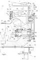
図3,4,5に示すように、機体フレーム1に、タンクフレーム体15が脱穀装置11と機体横方向に並んだ状態で立設されている。本実施例では、タンクフレーム体15は、脱穀装置11の機体右横側に位置している。タンクフレーム体15は、複数の支柱フレーム16と、上部フレーム17とを備えている。複数の支柱フレーム16は、機体前後方向に間隔を空けて並んだ状態で機体フレーム1に立設されている。上部フレーム17は、図5に示すように、第一上部フレーム部17aと、複数の第二上部フレーム部17bとを備えている。第一上部フレーム部117aは、機体前後方向に延びるフレーム部であって、複数の支柱フレーム16の上部に連結されている。複数の第二上部フレーム部17bは、第一上部フレーム部17aの機体前後方向での複数個所から機体横内側に機体横方向に延び、延出端部で脱穀装置11の機体横内側の側壁に連結されている。タンクフレーム体15の上部は、上部フレーム17によって脱穀装置11に連結されている。複数の支柱フレーム16のうちの最も前側の支柱フレーム16の上下方向での途中箇所と、脱穀装置11の機体横内側の側壁とが前連結フレーム18によって連結されている。 As shown in FIGS. 3, 4, and 5, a
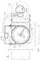
穀粒タンク12は、図4に示すように、タンクフレーム体15の上方と脱穀装置11の上方とに亘って配置されている。図3,5,6に示すように、穀粒タンク12の内部の下端部12aに、底スクリュー19が設けられている。穀粒タンク12の前壁部12fに、下端部12aに連通する排出口20が形成されている。穀粒タンク12の前壁部12fから円筒状の連結部21が前方向きに突設されている。連結部21は、排出口20の外周囲に位置している。穀粒タンク12の後壁部12rから支軸22が後方向きに突設されている。 As shown in FIG. 4, the
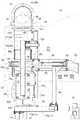
穀粒タンク12の前側において、図3,10に示すように、接続ケース23が上部フレーム17の前端部に支持されている。具体的には、接続ケース23の下端部に連結座部23aが一体的に成形されている。連結座部23aが第一上部フレーム部17aの前端部と、最も前側の第二上部フレーム部17bとに連結ボルトによって固定されている。接続ケース23は、L字形状に構成され、機体前後方向に延びる軸芯を有した筒状の第一ケース部23bと、機体上下方向に延びる軸芯を有した筒状の第二ケース部23cとを備えている。第一ケース部23bは、後方向きに開口している。第二ケース部23cは、上方向きに開口している。接続ケース23は、全体に亘って鋳造によって作製されている。連結部21が、第一ケース部23bの後端部の内周部に嵌合され、接続ケース23に相対回転可能に支持されている。 As shown in FIGS. 3 and 10, the
穀粒タンク12の後側において、図3に示すように、支持部材24が第二上部フレーム部17bから上方向きに突設されている。支軸22が支持部材24の上端部に相対回転可能に支持されている。 On the rear side of the
穀粒タンク12は、底スクリュー19の機体前後方向に延びる軸芯Pを揺動中心として上下揺動可能にタンクフレーム体15に支持されている。複数の支柱フレーム16のうちの一つの支柱フレーム16と穀粒タンク12の下部とに亘ってタンク昇降シリンダ25(図3,5参照)が連結されている。タンク昇降シリンダ25は、油圧シリンダによって構成されている。穀粒タンク12をタンク昇降シリンダ25によって軸芯Pを揺動昇降中心として下降貯留姿勢と上昇排出姿勢とに亘って昇降操作できる。 The
穀粒タンク12を下降貯留姿勢にすると、穀粒タンク12は、左端側が脱穀装置11の上端近くに下降した状態となって、穀粒タンク12の供給口と揚穀装置14の吐出口とが連通し、揚穀装置14によって供給される穀粒を穀粒タンク12に貯留できる。穀粒タンク12を上昇排出姿勢にすると、穀粒タンク12は、左端側が下端部12aよりも上昇した傾斜状態となり、貯留された穀粒を自然流下によって下端部12aへ移動させて底スクリュー19に供給できる。 When the
図4,6に示すように、穀粒タンク12の内部に流下ガイド28が設けられている。流下ガイド28は、底スクリュー19の上方に位置している。流下ガイド28は、穀粒を左右の傾斜ガイド部28aによって底スクリュー19の両横側に分れて流下するように案内する。流下ガイド28は、多量の穀粒が底スクリュー19に一気に流下しなしように穀粒の流下量を傾斜ガイド部28aとタンク壁との隙間によって規制する。 As shown in FIGS. 4 and 6, a
左右の傾斜ガイド部28aの下端部に、穀粒タンク12の前後方向に間隔を空けて並ぶ複数の切欠き部29が設けられている。穀粒タンク壁の内面に補強フレーム30が設けられている。補強フレーム30を切欠き部29に入り込ませることで、傾斜ガイド部28aの先端とタンク壁との隙間の大きさが穀粒の流下量を所定量に規制するための大きさに設定されている。 A plurality of
図7に示すように、傾斜ガイド部28aの先端部28bは、基端部に連結ボルトによって締め付け連結されている。先端部28bのボルト孔28cが長孔に形成されている。先端部28bの基端部への取付け位置をボルト孔28cの長孔形状によって変更することで、先端部28bが基端部から突出する長さを調節でき、傾斜ガイド部28aの先端とタンク壁との隙間を広く調節したり、狭く調節したりできる。 As shown in FIG. 7, the
流下ガイド28の前端側及び後端側は、図6,7に示す取付け構造に基づいて穀粒タンク12の前壁部12fまたは後壁部12rに連結されている。すなわち、流下ガイド28の支軸28dの端部に取付プレート31が固定されている。取付プレート31よりも穀粒タンク内側において、固定プレート32が切欠き部32aによって支軸28dに上方から装着されている。固定プレート32に固定された左右一対の取付ボルト33の先端側が取付プレート31のボルト孔31a、及び前壁部12fまたは後壁部12rのボルト孔を通して穀粒タンク12の外部に突出されている。穀粒タンク12の外部において、各取付ボルト33にネジ部材34が装着されている。ネジ部材34の締め付け力によって固定プレート32が前壁部12fまたは後壁部12rの内面に引き寄せられ、取付プレート31が固定プレート32によって前壁部12fまたは後壁部12rに押し付け固定されている。 The front end side and the rear end side of the
穀粒タンク12は、下降貯留姿勢から40度上昇揺動されると、上昇限界となる。穀粒タンク12が下降貯留姿勢から20度上昇揺動されたとき、流下ガイド28の支軸28dの軸芯と底スクリュー19の回転軸芯とを通る直線が鉛直線となり、左右の傾斜ガイド部28aの鉛直線に対する傾斜角が同じに又はほぼ同じになる。 When the
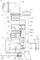
図3に示すように、接続ケース23から機体上方向きに延出された縦搬送部41と、縦搬送部41の上端部から横向きに延出された横搬送部45とによって、穀粒排出装置40が構成されている。穀粒タンク12に貯留された穀粒を穀粒排出装置40によって機外へ排出できる。穀粒排出装置40は、次の如く構成されている。縦搬送部41は、機体横外側からカバー39(図1,2参照)によって覆われている。カバー39には、機体横外側に膨らんだ突部39a(図1,2参照)が備えられている。後述するモータ55とカバー39との間隙を突部39aによって形成でき、カバー39を縦搬送部41に寄せても、カバー39がモータ55に接触ことを回避できる。 As shown in FIG. 3, the grain discharging device includes a
縦搬送部41は、図10,16に示すように、機体上下方向に延びる搬送筒42と、搬送筒42の内部に回転駆動可能に設けられた縦スクリュー43とを備えている。搬送筒42の下端部が第二ケース部23cの上端部における内周部に嵌入され、縦搬送部41は、接続ケース23を介して穀粒タンク12の下端部12aに接続されている。 As shown in FIGS. 10 and 16, the
横搬送部45は、図3に示すように、搬送筒46と、搬送筒46の内部に回転駆動可能に設けられた横スクリュー47とを備えている。縦搬送部41の上端部にL字形状の連結ケース部44が設けられている。搬送筒46が連結ケース部44から横向きに延出されている。横搬送部45の搬送筒46が連結ケース部44を介して縦搬送部41の搬送筒42に連通している。図8,9に示すように、搬送筒46の先端部に排出口48が備えられている。排出口48に連通した吐出筒49が搬送筒46の先端部から下向きに延出されている。 As shown in FIG. 3, the
搬送筒46の先端部の内部にシャッタ50が支軸51を介して支持されている。シャッタ50は、支軸51の水平方向に延びる軸芯を揺動中心として揺動昇降されることによって排出口48を開閉する。シャッタ50は、スプリング52によって閉じ姿勢に揺動付勢されている。スプリング52は、穀粒が排出されるとき、シャッタ50に作用する穀粒の搬送圧によって弾性変形され、シャッタ50が搬送圧によって開き姿勢に切り換え操作されることを許容する。本実施例では、シャッタ50を閉じ姿勢に付勢する付勢機構としてスプリング52を採用している。スプリング52に限らず、ウエイト、ゴム材など、各種の部材を採用してもよい。 A
図5,10に示すように、接続ケース23にモータ55が支持されている。モータ55と底スクリュー19とが接続ケース23を介して連動連結されている。具体的には、接続ケース23に動力伝達機構56が装備され、モータ55と底スクリュー19とは、接続ケース23及び動力伝達機構56を介して連動連結されている。底スクリュー19をモータ55によって駆動できる。 As shown in FIGS. 5 and 10, the
具体的には、図10に示すように、底スクリュー19の底スクリュー軸60には、スクリュー羽根19aが設けられた軸本体61と、接続ケース23の内部に軸本体61と一直線状に並んで位置する軸端部62とが備えられている。軸端部62は、両端側部分で軸受部材63を介して接続ケース23に回転可能に支持されている。軸端部62の軸本体側の部分に非円形部62aが設けられている。非円形部62aと軸本体61の端部とが相対回転不能に係合しており、軸端部62と軸本体61とが一体的に回転する。軸端部62の軸本体61と反対側の端部に、底スクリュー19の入力軸64が一体的に形成されている。 Specifically, as shown in FIG. 10, the
動力伝達機構56は、図10,11に示すように、動力伝達ケース57と、動力伝達ケース57の入力側部に収容された入力回転体58と、動力伝達ケース57の出力側部に収容された出力回転体59とを備えている。入力回転体58は、モータ55の出力軸55aと一体的に回転する状態で出力軸55aに設けられている。出力回転体59は、底スクリュー19の入力軸64と一体的に回転する状態で入力軸64に設けられている。入力回転体58と出力回転体59とは、無端チェーン59aによって連動連結されている。 As shown in FIGS. 10 and 11, the
動力伝達機構56は、軸端部62の両端側部分のうち、軸本体61とは反対側の端側部分にモータ55を連動連結している。動力伝達ケース57を取り外して、軸端部62とモータ55との連動連結を解除しても、軸端部62は、軸受部材63を介して接続ケース23に支持されているので、底スクリュー19の芯ずれを防止できる。 The
動力伝達ケース57は、図10,11,13に示すように、出力側部で接続ケース23に支持されている。動力伝達ケース57は、接続ケース23に対して穀粒タンク12が位置する側と反対側に配置されている。動力伝達ケース57が接続ケース23と穀粒タンク12との間に位置するのに比べ、接続ケース23を穀粒タンク12に近付けられる。動力伝達ケース57は、入力側部が接続ケース23よりも機体右横外側に位置する状態で接続ケース23に支持されている。モータ55は、動力伝達ケース57の入力側部に支持されることで接続ケース23に支持されている。モータ55は、接続ケース23の機体右横外側に配置されている。機体の横外側からモータ55に手が届き易い。モータ55は、動力伝達ケース57の入力側部から穀粒タンク側へ突出する状態で動力伝達ケース57に片持ち支持されている。穀粒タンク12の後端から接続ケース23の前端までの距離を短くしつつ、モータ55を装備できる。 The
縦搬送部41は、接続ケース23を介して底スクリュー19に連動連結されている。具体的には、図10に示すように、軸端部62にベベルギヤ67が相対回転不能に支持されている。このベベルギヤ67に噛み合っているベベルギヤ68が縦スクリュー軸43aの下端部のうち、接続ケース23の内部に位置する部分に相対回転不能に支持されている。接続ケース23の内部において、縦搬送部41の搬送軸としての縦スクリュー軸43aが底スクリュー19の底スクリュー軸60に連動連結されている。 The
縦スクリュー43と横スクリュー47とが連結ケース部44の内部でギヤ機構(図示せず)を介して連動連結されている。 The
図3に示すように、タンクフレーム体15の支柱フレーム16に油圧ポンプ65が支持されている。油圧ポンプ65から油圧ホース66が支柱フレーム16に沿って上向きに延出され、上向きの延出端部から上部フレーム17のうちの第一上部フレーム部17aに沿って前向きに延出されてモータ55に接続されている。モータ55は、油圧ポンプ65によって油圧ホース66を介して給排される作動油によって駆動される。タンクフレーム体15を油圧ホース66のガード部材に活用したガード構造によって油圧ホース66を保護できる。 As shown in FIG. 3, a
図10に示すように、縦搬送部41の搬送筒42の下端部が第二ケース部23cの上端部に相対回転可能に嵌入されている。穀粒排出装置40は、縦搬送部41の縦スクリュー43の軸芯Yを旋回中心として水平旋回のみ可能に接続ケース23に支持されている。搬送筒42と接続ケース23とに亘って抜止め装置70が設けられている。縦搬送部41が接続ケース23から抜け外れることを抜止め装置70によって防止されている。 As shown in FIG. 10, the lower end part of the
抜止め装置70は、具体的には、図10,11に示す如く構成されている。すなわち、抜止め装置70には、搬送筒42の外周部に備えられたフランジ71と、搬送筒42の外周囲に分散した複数のローラ72とが備えられている。ローラ72は、軸受部材によって構成されている。フランジ71は、搬送筒42の外周部に固定され、搬送筒42と一体に回転する。各ローラ72は、支持部材73の延出端部に支軸74を介して支持されている。支持部材73は、第二ケース部23cから上方へ延出されている。 Specifically, the retaining
抜止め装置70は、ローラ72がフランジ71を上方から押圧することで、縦搬送部41を接続ケース23から抜け外れないように支持している。搬送筒42が回転したとき、ローラ72は、フランジ71との接触によって支軸74の搬送筒42の径方向に延びる軸芯を回転中心として回転しつつフランジ71を上方から押圧する。 The retaining
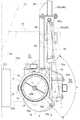
図11〜15に示すように、縦搬送部41の外周部に操作部76が設けられている。操作部76に油圧シリンダ78が連結されている。具体的には、油圧シリンダ78のロッド79の端部79aが操作部76に連結されている。本実施例では、操作部76にロッド79が連結されているが、操作部76にチューブ80を連結してもよい。油圧シリンダ78は、複動型の油圧シリンダによって構成されている。操作部76が油圧シリンダ78の伸縮によって押し引き操作されることで穀粒排出装置40が旋回操作され、穀粒排出装置40を油圧シリンダ78によって排出姿勢H(図16参照)と格納姿勢N(図1,2,16参照)とに亘って旋回操作できる。 As shown in FIGS. 11 to 15, an
穀粒排出装置40が排出姿勢Hになると、横搬送部45が走行機体の右横外側へ張り出た状態になる。穀粒排出装置40が格納姿勢Nになると、横搬送部45が機体内側に格納された状態になる。本実施例では、穀粒排出装置40が格納姿勢Nになると、横搬送部45は、穀粒タンク12の上方に機体後方向に延びた状態で位置する。このとき、図1に示すように、吐出筒49がエンジン冷却部38の吸気塔38aよりも後方に位置する。 When the
作業走行及び移動走行をする場合、運転部7において操作装置(図示せず)によってタンク昇降シリンダ25の制御弁(図示せず)を操作し、穀粒タンク12をタンク昇降シリンダ25によって下降貯留姿勢に姿勢変更することで、穀粒タンク12に穀粒を貯留できる。操作装置によって油圧シリンダ78の制御弁(図示せず)を操作し、穀粒排出装置40を油圧シリンダ78によって格納姿勢Nに旋回操作することで、横搬送部45を機体内側へ格納できる。 When working and moving, the
穀粒タンク12に貯留された穀粒を走行機体の横側に位置する運搬車の荷台などの供給先に排出する場合、操作装置によって油圧シリンダ78の制御弁を操作し、穀粒排出装置40を油圧シリンダ78によって排出姿勢Hに旋回操作し、操作装置によってタンク昇降シリンダ25の制御弁を操作し、穀粒タンク12をタンク昇降シリンダ25によって上昇排出姿勢に姿勢変更し、操作装置(図示せず)によってモータ55の制御弁(図示せず)を操作し、底スクリュー19をモータ55によって駆動することで、穀粒を供給先に排出できる。 When the grains stored in the
すなわち、穀粒タンク12の下端部12aに位置する穀粒が底スクリュー19によって機体前方側へ搬送されて排出口20から排出される。底スクリュー19による穀粒排出が進むに伴い、穀粒タンク12の左端側に位置する穀粒が自然流下によって下端部12aへ流動して底スクリュー19によって排出口20から排出される。底スクリュー19の駆動力によって縦搬送部41が駆動され、縦搬送部41の駆動力によって横搬送部45が駆動され、穀粒タンク12から排出された穀粒が縦搬送部41によって横搬送部45へ搬送され、横搬送部45によって排出口48へ搬送される。排出口48へ搬送された穀粒がシャッタ50をスプリング52に抗して押し開けて吐出筒49に入り、吐出筒49から供給先へ吐出される。 That is, the grain located at the
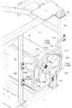
図12,14に示すように、油圧シリンダ78のチューブ80がロッド79よりも機体横内側に配置されている。油圧シリンダ78を機体横外側に突出しないように配備できる。チューブ80は、図11,13,14に示すように、機体側の支持部材としての支持フレーム85に連結されて支持されている。具体的には、支持フレーム85における中途部86に、基端部86aと、基端部86aから縦搬送部側に延出する支持部86bとが備えられている。支持部86bに、チューブ80の端部80aが連結されている。 As shown in FIGS. 12 and 14, the
図4に示すように、支持フレーム85のうち、油圧シリンダ78の端部80aから機体横内側に延出している下端側部87における延出端87aが入力ケース88に連結されている。入力ケース88は、脱穀装置11に固定されている。脱穀装置11は、機体フレーム1に支持されている。つまり、支持フレーム85は、入力ケース88及び脱穀装置11を介して機体フレーム1に連結されるので、機体側の支持部材となる。入力ケース88は、エンジン5からの駆動力を扱胴などに伝達するギヤ機構(図示せず)を収容している。 As shown in FIG. 4, in the
平面視において、支持フレーム85の下端側部87は、油圧シリンダ78の端部80aが位置する部位から機体横内側に向かって油圧シリンダ78の伸縮方向に沿って延びている。下端側部87の延出端87aが入力ケース88に連結されている。入力ケース88は、脱穀装置11に固定されているので、支持フレーム85の延出端87aは、脱穀装置11に連結されることになる。脱穀装置11は、機体フレーム1に固定されているので、支持フレーム85の延出端87aは、機体に支持された固定部に連結されていることになる。油圧シリンダ78を旋回操作反力に抗して支持フレーム85に支持させるのに、旋回操作反力の方向に沿った方向で支持させられる。 In plan view, the lower
支持フレーム85は、図4,13,14に示すように、中途部86における支持部86bにおいて、支持フレーム用の支柱フレーム89に支持されている。支柱フレーム89は、タンクフレーム体15から立設されている。詳しくは、支柱フレーム89は、タンクフレーム体15の第二上部フレーム部17bから立設されている。支柱フレーム89は、丈夫な構造のタンクフレーム体15によって安定的に支持されつつ支持フレーム85し、支持フレーム85は、安定的に支持される。支持フレーム85によって油圧シリンダ78を支持させるのに、旋回操作反力に抗してしっかり支持させられる。 As shown in FIGS. 4, 13, and 14, the
操作部76は、図12に示すように、縦搬送部41の外周部に沿った水平姿勢の円弧形状に形成されている。油圧シリンダ78によって操作部76に付与される旋回操作力を縦搬送部41の周方向での広い範囲に分散させて縦搬送部41に作用させられる。操作部76は、上下一対の水平プレート部76aと、縦プレート部76bとを備えている。上下の水平プレート部76aのうち、油圧シリンダ78に連結されている側の端部どうしが縦プレート部76bによって連結されている。上下の水平プレート部76aが縦搬送部41の外周部に沿った円弧形状に形成されている。操作部76は、当て板77を介して搬送筒42の外周部に連結されている。 As illustrated in FIG. 12, the
油圧シリンダ78は、操作部76と支持フレーム85とに水平姿勢で支持されている。油圧シリンダ78の端部79aが操作部76に連結ピン81を介して回転可能に連結されている。油圧シリンダ78の端部80aが支持部86bに連結ピン82を介して回転可能に連結されている。穀粒排出装置40を旋回操作するとき、操作部76と端部79aとの間のこじれ、及び支持部86bと端部80aとの間のこじれを発生させずに、油圧シリンダ78の操作力を操作部76に作用させられる。 The
油圧シリンダ78は、縦搬送部41に対して穀粒タンク12が位置する側と反対側において、穀粒タンク12のうち油圧シリンダ78が対向する対向面12s(図12参照)に沿う状態で設けられている。油圧シリンダ78は、対向面12sに沿って伸縮する状態で支持されている。油圧シリンダ78が穀粒タンク12と縦搬送部41との間に位置するのに比べ、縦搬送部41を穀粒タンク12に近付けられる。 The
図12に示すように、穀粒排出装置40を排出姿勢Hと格納姿勢Nとに亘って旋回操作するとき、油圧シリンダ78と操作部76との連結点X(連結ピン81の軸芯)が移動範囲Sを移動する。連結点Xが移動範囲Sの中央に位置したとき、油圧シリンダ78の軸芯78aが、縦搬送部41の外周部に沿う曲線Kの連結点Xにおける接線Lに沿う状態で油圧シリンダ78が配備されている。油圧シリンダ78の操作力を操作部76に旋回操作力として効率良く作用させつつ、穀粒排出装置40を排出姿勢Hと格納姿勢Nとにわたって旋回操作できる。 As shown in FIG. 12, when the
図4に示すように、穀粒タンク12の上面12tに保持部90が設けられている。穀粒排出装置40を格納姿勢Nにしたとき、横搬送部45を保持部90によってずれ動き難いように保持できる。 As shown in FIG. 4, a holding
すなわち、保持部90は、図4に示すように、折り曲げ状態の板バネによって構成され、機体横方向に間隔を空けて並ぶ一対の上向き折曲げ突部91,92と、機体横内側の上向き折曲げ突部91の下部に連なった取付部93とを備えている。取付部93が穀粒タンク12の上面12tに連結されていることで、保持部90は、機体横内側の上向き折曲げ突部92が位置する側の部分で上面12tに支持され、保持部90のうち、機体横外側の上向き折曲げ突部91が遊端側となる。 That is, as shown in FIG. 4, the holding
穀粒排出装置40が格納姿勢Nに向けて旋回するとき、横搬送部45は、機体横外側の上向き折曲げ突部91を上方から押圧し、上向き折曲げ突部91の側が上向き折曲げ突部92の側を揺動支点側にして下降揺動する状態に保持部90を弾性変形させつつ機体横内側へ移動する。穀粒排出装置40が格納姿勢Nになると、横搬送部45が一対の上向き折曲げ突部91,92の間に位置し、保持部90は、先の弾性変形によって備えた上方向きの付勢力を発揮して下降していた上向き折曲げ突部91を元の位置に上昇させ、横搬送部45を一対の上向き折曲げ突部91,92によって両横側から挟む。 When the
穀粒排出装置40が格納姿勢Nから排出姿勢Hへ旋回するとき、横搬送部45は、機体横外側の上向き折曲げ突部91を上方から押圧し、上向き折曲げ突部91の側が上向き折曲げ突部92の側を揺動支点側にして下降揺動する状態に保持部90を弾性変形させつつ機体横外側へ移動し、保持部90から機体右横外側へ抜け出る。 When the
機体横外側の上向き折曲げ突部91の下方において、取付部93からストッパー94が上向きに突設されている。ストッパー94は、下降揺動した上向き折曲げ突部91の側を下方から受け止めて、上向き折曲げ突部91の下降限界を設定する。 A
図5,12,14に示すように、縦搬送部41の近くに、機体上下方向に延びる縦フレーム95が縦搬送部41に寄り沿う状態で設けられている。縦フレーム95の下部が接続ケース23に支持され、縦フレーム95の上部に縦搬送部41が支持されている。縦搬送部41が横搬送部45の荷重によって傾斜することを縦フレーム95によって防止できる。 As shown in FIGS. 5, 12, and 14, a
縦フレーム95は、具体的には、図5及び図12から15に示す如く構成されている。
縦フレーム95は、第一縦フレーム96及び第二縦フレーム97を備えている。第一縦フレーム96は、図16に示すように、縦搬送部41に対して、穀粒排出装置40が格納姿勢となったときの排出口48とは反対側の位置に設けられている。第一縦フレーム96の下部96dに板状の連結部98が設けられている。連結部98は、複数本の連結ボルトによって接続ケース23に連結され、第一縦フレーム96の下部96dを接続ケース23に支持させている。第一縦フレーム96の上部96uにバンド状の支持部99が設けられている。支持部99は、縦搬送部41の上部における外周部に嵌合され、縦搬送部41の上部を第一縦フレーム96の上部96uに回転可能に支持させている。Specifically, the
The
穀粒排出装置40が格納姿勢Nに旋回されると、縦搬送部41の上端部から後方向きに延出した状態になった横搬送部45の荷重が縦搬送部41に掛かる。このとき、第一縦フレーム96は、縦搬送部41に対して排出口48が位置する側と反対側に位置するので、第一縦フレーム96が横搬送部45によって掛かる荷重に効果的に対抗する状態で縦搬送部41を支持する。 When the
第二縦フレーム97は、図16に示すように、縦搬送部41に対して、穀粒排出装置40が排出姿勢Hとなったときの排出口48とは反対側の位置に設けられている。第二縦フレーム97の下部97dに板状の連結部100が設けられている。連結部100は、複数本の連結ボルトによって接続ケース23に連結され、第二縦フレーム97の下部97dを接続ケース23に支持させている。第二縦フレーム97の上部97uにバンド状の支持部101が設けられている。支持部101は、縦搬送部41の上部における外周部に嵌合され、縦搬送部41の上部を第二縦フレーム97の上部97uに回転可能に支持させている。 As shown in FIG. 16, the second
穀粒排出装置40が排出姿勢Hに旋回されると、縦搬送部41の上端部から機体横外側へ延出した状態となった横搬送部45の荷重が縦搬送部41に掛かる。このとき、第二縦フレーム97は、縦搬送部41に対して排出口48が位置する側と反対側に位置するので、第二縦フレーム97が横搬送部45によって掛かる荷重に効果的に対抗する状態で縦搬送部41を支持する。 When the
図4,14,15に示すように、第一縦フレーム96の上端部と第二縦フレーム97の上端部とが連結フレーム102によって連結されている。連結フレーム102は、図16に示すように、縦搬送部41に対して、穀粒排出装置40が旋回されたときの排出口48の軌跡とは反対側の位置に設けられている。連結フレーム102は、第一縦フレーム96の支持部99よりも上方で、第二縦フレーム97の支持部101よりも下方に位置している。 As shown in FIGS. 4, 14, and 15, the upper end portion of the first
穀粒排出装置40が排出姿勢Hと格納姿勢Nとの一方から他方へ移動するときなど、穀粒排出装置40が排出姿勢Hと格納姿勢Nとの間に位置すると、横搬送部45が排出姿勢Hのときの延出方向と、格納姿勢Nのときの延出方向との間の延出方向に延出する状態で縦搬送部41から延出し、この延出状態の横搬送部45の荷重が縦搬送部41に掛かる。このとき、横搬送部45の荷重を連結フレーム102によって第一縦フレーム96と第二縦フレーム97とに分散させることができる。 When the
図5,12,15に示すように、縦フレーム95のうちの第一縦フレーム96と接続ケース23との間に空間103が形成されている。動力伝達機構56が第一縦フレーム96と接続ケース23との間に配置されている。詳しくは、動力伝達機構56のうち、底スクリュー19への出力する部分が第一縦フレーム96と接続ケース23との間に位置している。油圧シリンダ78は、空間103のうち、動力伝達機構56よりも上方に位置する上方領域において、縦搬送部41に連結されている。油圧シリンダ78が伸縮するとき、ロッド79が空間103の上方領域を通過して操作部76を操作する。動力伝達機構56及び油圧シリンダ78に石などが当たることを防止するガード機能を第一縦フレーム96に備えさせられる。 As shown in FIGS. 5, 12, and 15, a
図4,12,14に示すように、支持フレーム85は、第二縦フレーム97から脱穀装置側に向かって延びて入力ケース88に連結されて、脱穀装置11に支持されている。支持フレーム85は、タンクフレーム体15によって安定的に支持されている支柱フレーム89と、脱穀装置11とに支持され、安定的に支持されている。支持フレーム85が第二縦フレーム97から延出する方向が、穀粒排出装置40が排出姿勢となったときの排出口48とは反対側に向かう方向になっている。第二縦フレーム97を支持フレーム85によって支持させるのに、第二縦フレーム97に掛かる支持反力に効果的に対抗する状態で支持させることができる。第二縦フレーム97が縦搬送部41を横搬送部45による荷重に抗してしっかり支持するように、第二縦フレーム97を支持フレーム85によってしっかり補強できる。 As shown in FIGS. 4, 12, and 14, the
図15に示すように、第一縦フレーム96の近くを吸気管104が第一縦フレーム96に沿って機体上下方向に延びている。吸気管104は、エンジン5とプレエアクーナ105とを接続している。吸気管104は、図15,16に示すように、第一縦フレーム96に対向する部分104aを内側に凹入された状態で備え、第一縦フレーム96と吸気管104との間隔をあまり狭くならないように設定している。 As shown in FIG. 15, an
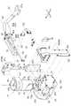
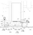
図17,18に示すように、エンジン5は、走行機体4の右横端部に設けられている。走行機体4の右横側部にカバー107(図1参照)が設けられている。カバー107は、上下揺動可能なリンク機構(図示せず)を介して走行機体4に支持されている。カバー107は、下降閉じ姿勢と上昇開き姿勢とに亘って昇降操作できる。カバー107を下降閉じ姿勢にすることで、カバー107によってエンジン5を機体横外方側から覆い、エンジン5に土埃などが入ることをカバー107によって防止したり、抑制したりできる。カバー107を上昇開き姿勢にすることで、エンジン5の機体横外側を開放できる。 As shown in FIGS. 17 and 18, the
エンジン5とカバー107との間に、ファン108及び風ガイド部材109が設けられている。ファン108は、エンジン5に回転可能に支持されている。ファン108が備えるプーリと、エンジン5の出力軸が備えるプーリ110とに亘って無端ベルト111が装着されている。ファン108は、エンジン5が出力する駆動力によって回転駆動される。風ガイド部材109は、ファン108の外周を覆っている。 A
ファン108の送風作用により、機体外の空気がカバー107の吸気孔部107a(図18参照)を介してカバー107の内側に吸引されて風が発生され、発生した風が風ガイド部材109によって案内されてエンジン5に供給される。エンジン5を風によって冷却できる。エンジン5に飛んで来たワラ屑などの塵埃を風によって除去できる。 Due to the blowing action of the
図18に示すように、エンジン5とカバー107との間にエンジンガード113が設けられている。走行機体4の横外側に位置した運搬車がカバー107に当たるなどにより、カバー107が変形や破損されて機体内側に入り込むことがあっても、カバー107は、エンジン5の機体横外側でエンジンガード113によって受け止められる。機体内側に入り込んだカバー107がエンジン5に当たることを回避し易いように、エンジン5がエンジンガード113によって保護される。 As shown in FIG. 18, an
エンジンガード113は、具体的には、次の如く構成されている。
エンジンガード113は、図17,18に示すように、走行機体4の上下方向に延びる前縦ガード114と、走行機体4の上下方向に延びる後縦ガード115と、走行機体の前後方向に延びる横ガード116とを備えている。Specifically, the
As shown in FIGS. 17 and 18, the
前縦ガード114は、エンジン5の前部の機体横外側に位置している。後縦ガード115は、エンジン5の後部の機体横外側に位置している。横ガード116は、エンジン5の上部の機体横外側に位置している。 The front
タンクフレーム体15は、穀粒タンク12をエンジン5の上方に位置させて支持している。タンクフレーム体15において機体前後方向に隣り合っている二つの支柱フレーム16がエンジン5の前後に振り分けて立設されている。前後の支柱フレーム16にエンジンガード113が支持されている。 The
具体的には、図17に示すように、横ガード116の前端部から上前連結アーム117が延出され、横ガード116の後端部から上後連結アーム118が延出されている。上前連結アーム117及び上後連結アーム118は、横ガード116に一体的に形成されている。前縦ガード114と後縦ガード115とが横ガード116によって連結されている。具体的には、前縦ガード114の上端側と、後縦ガード115の上端側とが横ガード116によって連結されている。前縦ガード114の下端部から下前連結アーム119が延出されている。下前連結アーム119は、前縦ガード114に一体的に形成されている。後縦ガード115の下端部から下後連結アーム120が延出されている。下後連結アーム120は、後縦ガード115に一体的に形成されている。 Specifically, as shown in FIG. 17, the upper
上前連結アーム117の延出端部が前の支柱フレーム16に連結ボルトによって連結されている。上後連結アーム118の延出端部が後の支柱フレーム16に連結ボルトによって連結されている。下前連結アーム119の延出端部が前の支柱フレーム16に連結ボルトによって連結されている。下後連結アーム120の延出端部が後の支柱フレーム16に連結ボルトによって連結されている。 The extended end of the upper
エンジンガード113の機体横外側端部113aがファン108の機体横外側端部108aよりも機体横外方側に配置されている。カバー107が機体内側に入り込んでも、カバー107は、ファン108の機体横外側でエンジンガード113によって受け止められる。機体内側に入り込んだカバー107がファン108に当たることを回避し易いように、ファン108がエンジンガード113によって保護される。 An airframe lateral
すなわち、図17,18に示すように、前縦ガード114の機体横外側端部114a、後縦ガード115の機体横外側端部115a、及び横ガード116の機体横外側端部116aによってエンジンガード113の機体横外側端部113aが形成されている。前縦ガード114の機体横外側端部114a、後縦ガード115の機体横外側端部115a、及び横ガード116の機体横外側端部116aがファン108の機体横外側端部108aよりも機体横外方側に位置している。 That is, as shown in FIGS. 17 and 18, the
風ガイド部材109は、前縦ガード114と後縦ガード115との間に配置され、横ガード116に吊り下げ支持されている。具体的には、図17に示すように、横ガード116の前後方向での二箇所から上支持部材121が下方向きに延出されている。前の上支持部材121の延出端部、及び後の上支持部材121の延出端部に風ガイド部材109の上部が連結されている。 The
風ガイド部材109の前部が前縦ガード114に支持され、風ガイド部材109の後部が後縦ガード115に支持されている。具体的には、前縦ガード114から前支持部材122が後向きに延出されている。前支持部材122の延出端部に風ガイド部材109の前部が連結されている。後縦ガード115から後支持部材123が前向きに延出されている。後支持部材123の延出端部に風ガイド部材109の後部が連結されている。 The front portion of the
〔別実施形態〕
(1)上記した実施例では、縦搬送部41をオーガ式に構成した例を示したが、バケットコンベヤ式に構成して実施してもよい。[Another embodiment]
(1) In the above-described embodiment, an example in which the
(2)上記した実施例では、横搬送部45を機体の右横外側へ張り出すよう構成した例を示したが、機体の左横外側あるいは機体の後外側へ張り出すよう構成して実施してもよい。(2) In the above-described embodiment, an example in which the
(3)上記した実施例では、穀粒排出装置40を格納姿勢ンにしたとき、横搬送部45が機体前後向きに延びる姿勢になるよう構成した例を示したが、機体前後方向に対して傾斜した姿勢になるよう構成してもよい。(3) In the above-described embodiment, when the
(4)上記した実施例では、穀粒タンク12を上昇排出姿勢と下降貯留姿勢とに揺動昇降可能に支持し、穀粒タンク12を上昇排出姿勢にすることで穀粒を底スクリュー19に流動させる例を示したが、姿勢変更不能とし、穀粒タンクの傾斜であるとか、底壁の傾斜などによって穀粒を底スクリュー19に流動させるよう構成してもよい。(4) In the above-described embodiment, the
(5)上記した実施例では、底スクリュー19を設けた例を示したが、底スクリュー19を設けず、穀粒タンクの傾斜であるとか、底壁の傾斜などによって穀粒を穀粒タンクから排出するよう構成してもよい。(5) Although the example which provided the
(6)上記した実施例では、穀粒排出装置40が水平旋回のみ行う例を示した、横搬送部45が縦搬送部41から上下揺動可能に延びるよう構成して実施してもよい。(6) In the above-described embodiment, the example in which the
(7)上記した実施例では、穀粒排出装置40を油圧シリンダ78によって旋回操作する例を示したが、モータによって旋回操作するよう構成して実施してもよい(7) In the above-described embodiment, the example in which the
(8)上記した実施例では、底スクリュー19を油圧モータ55によって駆動する例を示したが、底スクリュー19をエンジン5の駆動力によって駆動するよう構成して実施してもよい。(8) In the above-described embodiment, the example in which the
(9)上記した実施例では、第一縦フレーム96及び第二縦フレーム97を設けた例を示したが、いずれか一方だけを設けて実施してもよい。(9) In the above-described embodiment, the example in which the first
(10)上記した実施例では、連結フレーム102を設けた例を示したが、第一縦フレーム96及び第二縦フレーム97を設けても、連結フレーム102を設けずに実施してもよい。(10) In the above-described embodiment, an example in which the
(11)上記した実施例では、支持フレーム85を設けた例を示したが、支持フレーム85を設けずに実施してもよい。(11) In the above-described embodiment, the example in which the
(12)上記した実施例では、支柱フレーム89を設けた例を示したが、支柱フレーム89を設けずに実施してもよい。(12) In the above-described embodiment, an example in which the
(13)上記した実施例では、シャッタ50を設けた例を示したが、シャッタ50を設けずに実施してもよい。(13) In the above-described embodiment, an example in which the
本発明は、走行装置として車輪2,3を備えたものに限らず、クローラ走行装置を備えたもの、あるいは、ミニクローラと車輪とを備えたものにも利用可能である。 The present invention is not limited to the traveling device provided with the
1 機体フレーム
9 刈取部
11 脱穀装置
12 穀粒タンク
12a 下端部
12t 上面
23 接続ケース
40 穀粒排出装置
41 縦搬送部
45 横搬送部
48 排出口
50 シャッタ
52 付勢機構(スプリング)
78 油圧シリンダ
85 支持フレーム
86 中途部
87a 延出端
88 固定部(入力ケース)
89 支柱フレーム
90 保持部
91 上向き折曲げ突部
92 上向き折曲げ突部
95 縦フレーム
96 第一縦フレーム
97 第二縦フレーム
102 連結フレーム
H 排出姿勢
N 格納姿勢
P 軸芯
Y 軸芯DESCRIPTION OF
78
89
Claims (12)
Translated fromJapanese前記穀粒タンクの下端部に接続されたL字形状の接続ケースが備えられ、
前記穀粒排出装置に、前記接続ケースに接続されて上方向に延びる縦搬送部と、前記縦搬送部の上端部に接続されて横方向に延び、先端部に排出口を有する横搬送部と、を備え、
前記穀粒排出装置は、前記縦搬送部の軸芯を旋回中心として、前記横搬送部が機体外側へ張り出す排出姿勢と、前記横搬送部が機体内側に格納されて前記穀粒タンクの上方に位置する格納姿勢とに亘り旋回可能であり、
前記縦搬送部に寄り添う状態で機体上下方向に沿って延び、前記縦搬送部を支持する縦フレームが備えられ、
前記縦フレームの下部が前記接続ケースに支持され、かつ、前記縦フレームの上部に前記縦搬送部が支持されているコンバイン。A threshing device for threshing the harvested cereals harvested by the reaping unit, a grain tank for storing the grain obtained by the threshing device, and discharging the grain stored in the grain tank to the outside of the machine A grain discharging device,
An L-shaped connection case connected to the lower end of the grain tank is provided,
A vertical conveying unit connected to the connection case and extending upward in the grain discharging device, a horizontal conveying unit connected to the upper end of the vertical conveying unit and extending in the horizontal direction, and having a discharge port at the tip. With
The grain discharging device includes a discharging posture in which the horizontal conveying unit projects to the outside of the machine body with the axial center of the vertical conveying unit as a turning center, and the horizontal conveying unit is stored inside the machine body so as to be above the grain tank. Can be swung over the retracted position located at
A vertical frame is provided that extends along the vertical direction of the machine body in a state of snuggling up to the vertical conveyance unit and supports the vertical conveyance unit,
A combine in which the lower part of the vertical frame is supported by the connection case, and the vertical transport unit is supported by the upper part of the vertical frame.
前記第一縦フレームは、前記縦搬送部に対して、前記穀粒排出装置が前記格納姿勢となったときの前記排出口とは反対側の位置に設けられている請求項1に記載のコンバイン。The vertical frame includes a first vertical frame,
The combine according to claim 1, wherein the first vertical frame is provided at a position opposite to the discharge port when the grain discharge device is in the retracted position with respect to the vertical conveyance unit. .
前記第二縦フレームは、前記縦搬送部に対して、前記穀粒排出装置が前記排出姿勢となったときの前記排出口とは反対側の位置に設けられている請求項1に記載のコンバイン。The vertical frame includes a second vertical frame,
The combine according to claim 1, wherein the second vertical frame is provided at a position opposite to the discharge port when the grain discharge device is in the discharge posture with respect to the vertical conveyance unit. .
前記第二縦フレームは、前記縦搬送部に対して、前記穀粒排出装置が前記排出姿勢となったときの前記排出口とは反対側の位置に設けられている請求項2に記載のコンバイン。The vertical frame includes a second vertical frame,
The combine according to claim 2, wherein the second vertical frame is provided at a position opposite to the discharge port when the grain discharge device is in the discharge posture with respect to the vertical conveyance unit. .
前記連結フレームは、前記縦搬送部に対して前記排出口の軌跡とは反対側の位置に設けられている請求項4に記載のコンバイン。A connection frame connecting the first vertical frame and the second vertical frame;
The combine according to claim 4, wherein the connection frame is provided at a position opposite to the trajectory of the discharge port with respect to the vertical conveyance unit.
前記支持フレームは、前記第二縦フレームから、前記穀粒排出装置が前記排出姿勢となったときの前記排出口とは反対側に向けて延び、機体に支持された固定部に連結されている請求項3〜5のいずれか一項に記載のコンバイン。A support frame connected to the second vertical frame;
The support frame extends from the second vertical frame toward the opposite side of the discharge port when the grain discharge device is in the discharge posture, and is connected to a fixed portion supported by the machine body. The combine as described in any one of Claims 3-5.
前記穀粒タンクは、前記タンクフレーム体の上方と前記脱穀装置の上方とに亘って配置されており、
前記タンクフレーム体から支柱フレームが立設され、
前記支持フレームの延出端は前記脱穀装置に連結され、かつ、前記支持フレームの中途部は前記支柱フレームに支持されている請求項6に記載のコンバイン。The tank frame body that supports the grain tank and the threshing device are provided in the body frame in a state of being aligned in the lateral direction of the body,
The grain tank is disposed over the tank frame body and over the threshing device,
A support frame is erected from the tank frame body,
The combine according to claim 6, wherein an extended end of the support frame is connected to the threshing device, and a middle part of the support frame is supported by the support frame.
前記油圧シリンダの一端側は、前記縦搬送部の外周部に連結されている請求項1〜6のいずれか一項に記載のコンバイン。A hydraulic cylinder that is connected in a horizontal posture across the vertical conveying unit and the machine body side, and that rotates the grain discharging device by expansion and contraction is provided,
The combiner according to any one of claims 1 to 6, wherein one end side of the hydraulic cylinder is connected to an outer peripheral portion of the vertical conveyance unit.
前記油圧シリンダの一端側は、前記縦搬送部の外周部に連結され、
前記油圧シリンダの他端側が前記支持フレームに支持されている請求項7に記載のコンバイン。A hydraulic cylinder that is connected in a horizontal posture across the vertical conveying unit and the machine body side, and that rotates the grain discharging device by expansion and contraction is provided,
One end side of the hydraulic cylinder is connected to an outer peripheral portion of the vertical conveying unit,
The combine according to claim 7, wherein the other end side of the hydraulic cylinder is supported by the support frame.
前記保持部は、前記横搬送部を両横側から挟む一対の上向き折曲げ突部を備え、上方向きの付勢力を発揮する板バネによって構成され、
前記保持部は、一方の前記上向き折曲げ突部が遊端側となる状態で、前記保持部のうち他方の前記上向き折曲げ突部が位置する側の部分で前記穀粒タンクに支持され、
前記穀粒排出装置が前記格納姿勢から前記排出姿勢側へ旋回するとき及び前記格納姿勢へ旋回するとき、前記横搬送部が前記一方の上向き折曲げ突部を下方へ押圧して、前記保持部の遊端側が下げ揺動操作される請求項1〜9のいずれか一項に記載のコンバイン。On the upper surface of the grain tank, there is provided a holding part that holds the lateral conveying part from below when the grain discharging device turns to the retracted position,
The holding portion includes a pair of upward bent protrusions sandwiching the lateral conveying portion from both lateral sides, and is configured by a leaf spring that exerts an upward biasing force,
The holding portion is supported by the grain tank at a portion of the holding portion on the side where the other upward bent protrusion is located, with one of the upward bent protrusions on the free end side.
When the grain discharging device is swung from the retracted posture to the discharging posture and when it is swung to the retracted posture, the horizontal conveying portion presses the one upward bent protrusion downward, and the holding portion The combine according to any one of claims 1 to 9, wherein the free end side of the sway is lowered and swung.
前記排出口を開閉可能なシャッタと、前記シャッタを閉じ姿勢に付勢する付勢機構と、が備えられ、
前記シャッタは、穀粒が排出されるとき、穀粒の搬送圧によって開き姿勢に切り換え操作される請求項10に記載のコンバイン。The grain discharging device is configured to perform only horizontal turning,
A shutter capable of opening and closing the discharge port, and a biasing mechanism for biasing the shutter to a closed posture,
The combine according to claim 10, wherein when the grain is discharged, the shutter is operated to be switched to an open position by a conveying pressure of the grain.
前記穀粒タンクは、前記底スクリューのスクリュー軸芯を揺動中心として下降貯留姿勢と上昇排出姿勢とに亘って揺動昇降可能に支持されている請求項1〜11のいずれか一項に記載のコンバイン。A bottom screw for discharging the grain from the grain tank is provided at the lower end inside the grain tank,
The said grain tank is supported so that rocking | fluctuation raising / lowering is possible over the fall storage attitude | position and a raise discharge attitude | position with the screw shaft center of the said bottom screw as a rocking | swiveling center. Combine.
Priority Applications (3)
| Application Number | Priority Date | Filing Date | Title |
|---|---|---|---|
| JP2015255294AJP6532400B2 (en) | 2015-12-25 | 2015-12-25 | Combine |
| CN201621329763.1UCN207321982U (en) | 2015-12-25 | 2016-12-06 | Combine harvester |
| CN201611110477.0ACN106982588B (en) | 2015-12-25 | 2016-12-06 | Combine harvester |
Applications Claiming Priority (1)
| Application Number | Priority Date | Filing Date | Title |
|---|---|---|---|
| JP2015255294AJP6532400B2 (en) | 2015-12-25 | 2015-12-25 | Combine |
Publications (2)
| Publication Number | Publication Date |
|---|---|
| JP2017112973Atrue JP2017112973A (en) | 2017-06-29 |
| JP6532400B2 JP6532400B2 (en) | 2019-06-19 |
Family
ID=59231143
Family Applications (1)
| Application Number | Title | Priority Date | Filing Date |
|---|---|---|---|
| JP2015255294AExpired - Fee RelatedJP6532400B2 (en) | 2015-12-25 | 2015-12-25 | Combine |
Country Status (1)
| Country | Link |
|---|---|
| JP (1) | JP6532400B2 (en) |
Citations (10)
| Publication number | Priority date | Publication date | Assignee | Title |
|---|---|---|---|---|
| JPS6062914A (en)* | 1983-09-16 | 1985-04-11 | 井関農機株式会社 | Auger controller of combine |
| JPS61128945U (en)* | 1985-01-31 | 1986-08-13 | ||
| JPS61227708A (en)* | 1985-04-01 | 1986-10-09 | 井関農機株式会社 | Combine grain storage device |
| JPS632445U (en)* | 1986-06-21 | 1988-01-09 | ||
| JPH05207815A (en)* | 1992-01-30 | 1993-08-20 | Iseki & Co Ltd | Thresher in agricultural combine |
| JPH09187160A (en)* | 1996-01-09 | 1997-07-22 | Iseki & Co Ltd | Combine Glen Tank |
| US6012272A (en)* | 1998-03-18 | 2000-01-11 | Dillon; Ben N. | Articulated combine |
| JP2000217420A (en)* | 1999-01-29 | 2000-08-08 | Iseki & Co Ltd | Work vehicle grain discharger |
| JP2001204235A (en)* | 2000-01-25 | 2001-07-31 | Iseki & Co Ltd | Combine discharging device |
| JP2013192474A (en)* | 2012-03-16 | 2013-09-30 | Kubota Corp | Combine harvester |
- 2015
- 2015-12-25JPJP2015255294Apatent/JP6532400B2/ennot_activeExpired - Fee Related
Patent Citations (10)
| Publication number | Priority date | Publication date | Assignee | Title |
|---|---|---|---|---|
| JPS6062914A (en)* | 1983-09-16 | 1985-04-11 | 井関農機株式会社 | Auger controller of combine |
| JPS61128945U (en)* | 1985-01-31 | 1986-08-13 | ||
| JPS61227708A (en)* | 1985-04-01 | 1986-10-09 | 井関農機株式会社 | Combine grain storage device |
| JPS632445U (en)* | 1986-06-21 | 1988-01-09 | ||
| JPH05207815A (en)* | 1992-01-30 | 1993-08-20 | Iseki & Co Ltd | Thresher in agricultural combine |
| JPH09187160A (en)* | 1996-01-09 | 1997-07-22 | Iseki & Co Ltd | Combine Glen Tank |
| US6012272A (en)* | 1998-03-18 | 2000-01-11 | Dillon; Ben N. | Articulated combine |
| JP2000217420A (en)* | 1999-01-29 | 2000-08-08 | Iseki & Co Ltd | Work vehicle grain discharger |
| JP2001204235A (en)* | 2000-01-25 | 2001-07-31 | Iseki & Co Ltd | Combine discharging device |
| JP2013192474A (en)* | 2012-03-16 | 2013-09-30 | Kubota Corp | Combine harvester |
Also Published As
| Publication number | Publication date |
|---|---|
| JP6532400B2 (en) | 2019-06-19 |
Similar Documents
| Publication | Publication Date | Title |
|---|---|---|
| KR101974222B1 (en) | Crawler traveling device of working machine | |
| WO2018092764A1 (en) | Harvester | |
| JP2007037460A (en) | Combine | |
| CN207321982U (en) | Combine harvester | |
| JP3959101B2 (en) | Combine | |
| JP5451431B2 (en) | Crawler travel device | |
| JP6532399B2 (en) | Combine | |
| JP2010042031A (en) | Combine | |
| JP2017112973A (en) | Combine | |
| JP6635786B2 (en) | Combine | |
| JP5608131B2 (en) | Combine | |
| JP2015128413A (en) | Combine | |
| CN105451541A (en) | Combine Harvesters and Harvesters | |
| JP2014079222A (en) | Grain discharge structure of combine harvester | |
| JP6280785B2 (en) | Combine grain discharging device | |
| JP5975632B2 (en) | Combine grain discharge structure | |
| JP2012235762A (en) | Combine harvester | |
| JP5426862B2 (en) | Crawler travel device | |
| JP3841745B2 (en) | Combine | |
| JP5320804B2 (en) | Combine | |
| JP2015029455A (en) | Combine | |
| JP3652694B2 (en) | Combine | |
| JP6073057B2 (en) | Combine grain discharge structure | |
| JP3821770B2 (en) | Combine | |
| KR102310109B1 (en) | Work machine and combine |
Legal Events
| Date | Code | Title | Description |
|---|---|---|---|
| A621 | Written request for application examination | Free format text:JAPANESE INTERMEDIATE CODE: A621 Effective date:20171222 | |
| A977 | Report on retrieval | Free format text:JAPANESE INTERMEDIATE CODE: A971007 Effective date:20180829 | |
| A131 | Notification of reasons for refusal | Free format text:JAPANESE INTERMEDIATE CODE: A131 Effective date:20180925 | |
| A521 | Request for written amendment filed | Free format text:JAPANESE INTERMEDIATE CODE: A523 Effective date:20181122 | |
| TRDD | Decision of grant or rejection written | ||
| A01 | Written decision to grant a patent or to grant a registration (utility model) | Free format text:JAPANESE INTERMEDIATE CODE: A01 Effective date:20190423 | |
| A61 | First payment of annual fees (during grant procedure) | Free format text:JAPANESE INTERMEDIATE CODE: A61 Effective date:20190521 | |
| R150 | Certificate of patent or registration of utility model | Ref document number:6532400 Country of ref document:JP Free format text:JAPANESE INTERMEDIATE CODE: R150 | |
| LAPS | Cancellation because of no payment of annual fees |