JP2017112833A - Storage system and storage system control method - Google Patents
Storage system and storage system control methodDownload PDFInfo
- Publication number
- JP2017112833A JP2017112833AJP2017029513AJP2017029513AJP2017112833AJP 2017112833 AJP2017112833 AJP 2017112833AJP 2017029513 AJP2017029513 AJP 2017029513AJP 2017029513 AJP2017029513 AJP 2017029513AJP 2017112833 AJP2017112833 AJP 2017112833A
- Authority
- JP
- Japan
- Prior art keywords
- power
- storage battery
- mode
- charging
- supplied
- Prior art date
- Legal status (The legal status is an assumption and is not a legal conclusion. Google has not performed a legal analysis and makes no representation as to the accuracy of the status listed.)
- Pending
Links
Images


Classifications
- H—ELECTRICITY
- H02—GENERATION; CONVERSION OR DISTRIBUTION OF ELECTRIC POWER
- H02J—CIRCUIT ARRANGEMENTS OR SYSTEMS FOR SUPPLYING OR DISTRIBUTING ELECTRIC POWER; SYSTEMS FOR STORING ELECTRIC ENERGY
- H02J7/00—Circuit arrangements for charging or depolarising batteries or for supplying loads from batteries
- H02J7/34—Parallel operation in networks using both storage and other DC sources, e.g. providing buffering
- H02J7/35—Parallel operation in networks using both storage and other DC sources, e.g. providing buffering with light sensitive cells
- H—ELECTRICITY
- H02—GENERATION; CONVERSION OR DISTRIBUTION OF ELECTRIC POWER
- H02J—CIRCUIT ARRANGEMENTS OR SYSTEMS FOR SUPPLYING OR DISTRIBUTING ELECTRIC POWER; SYSTEMS FOR STORING ELECTRIC ENERGY
- H02J11/00—Circuit arrangements for providing service supply to auxiliaries of stations in which electric power is generated, distributed or converted
- H—ELECTRICITY
- H02—GENERATION; CONVERSION OR DISTRIBUTION OF ELECTRIC POWER
- H02J—CIRCUIT ARRANGEMENTS OR SYSTEMS FOR SUPPLYING OR DISTRIBUTING ELECTRIC POWER; SYSTEMS FOR STORING ELECTRIC ENERGY
- H02J7/00—Circuit arrangements for charging or depolarising batteries or for supplying loads from batteries
- H02J7/02—Circuit arrangements for charging or depolarising batteries or for supplying loads from batteries for charging batteries from AC mains by converters
- H—ELECTRICITY
- H02—GENERATION; CONVERSION OR DISTRIBUTION OF ELECTRIC POWER
- H02J—CIRCUIT ARRANGEMENTS OR SYSTEMS FOR SUPPLYING OR DISTRIBUTING ELECTRIC POWER; SYSTEMS FOR STORING ELECTRIC ENERGY
- H02J9/00—Circuit arrangements for emergency or stand-by power supply, e.g. for emergency lighting
- H02J9/04—Circuit arrangements for emergency or stand-by power supply, e.g. for emergency lighting in which the distribution system is disconnected from the normal source and connected to a standby source
- H02J9/06—Circuit arrangements for emergency or stand-by power supply, e.g. for emergency lighting in which the distribution system is disconnected from the normal source and connected to a standby source with automatic change-over, e.g. UPS systems
- H02J9/061—Circuit arrangements for emergency or stand-by power supply, e.g. for emergency lighting in which the distribution system is disconnected from the normal source and connected to a standby source with automatic change-over, e.g. UPS systems for DC powered loads
- H—ELECTRICITY
- H02—GENERATION; CONVERSION OR DISTRIBUTION OF ELECTRIC POWER
- H02B—BOARDS, SUBSTATIONS OR SWITCHING ARRANGEMENTS FOR THE SUPPLY OR DISTRIBUTION OF ELECTRIC POWER
- H02B1/00—Frameworks, boards, panels, desks, casings; Details of substations or switching arrangements
- H02B1/26—Casings; Parts thereof or accessories therefor
- H02B1/40—Wall-mounted casings; Parts thereof or accessories therefor
- H02B1/42—Mounting of devices therein
- H—ELECTRICITY
- H02—GENERATION; CONVERSION OR DISTRIBUTION OF ELECTRIC POWER
- H02J—CIRCUIT ARRANGEMENTS OR SYSTEMS FOR SUPPLYING OR DISTRIBUTING ELECTRIC POWER; SYSTEMS FOR STORING ELECTRIC ENERGY
- H02J7/00—Circuit arrangements for charging or depolarising batteries or for supplying loads from batteries
- H02J7/0042—Circuit arrangements for charging or depolarising batteries or for supplying loads from batteries characterised by the mechanical construction
- H02J7/0045—Circuit arrangements for charging or depolarising batteries or for supplying loads from batteries characterised by the mechanical construction concerning the insertion or the connection of the batteries
- Y—GENERAL TAGGING OF NEW TECHNOLOGICAL DEVELOPMENTS; GENERAL TAGGING OF CROSS-SECTIONAL TECHNOLOGIES SPANNING OVER SEVERAL SECTIONS OF THE IPC; TECHNICAL SUBJECTS COVERED BY FORMER USPC CROSS-REFERENCE ART COLLECTIONS [XRACs] AND DIGESTS
- Y02—TECHNOLOGIES OR APPLICATIONS FOR MITIGATION OR ADAPTATION AGAINST CLIMATE CHANGE
- Y02B—CLIMATE CHANGE MITIGATION TECHNOLOGIES RELATED TO BUILDINGS, e.g. HOUSING, HOUSE APPLIANCES OR RELATED END-USER APPLICATIONS
- Y02B10/00—Integration of renewable energy sources in buildings
- Y02B10/70—Hybrid systems, e.g. uninterruptible or back-up power supplies integrating renewable energies
Landscapes
- Engineering & Computer Science (AREA)
- Power Engineering (AREA)
- Business, Economics & Management (AREA)
- Emergency Management (AREA)
- Charge And Discharge Circuits For Batteries Or The Like (AREA)
- Stand-By Power Supply Arrangements (AREA)
- Supply And Distribution Of Alternating Current (AREA)
- Distribution Board (AREA)
- Secondary Cells (AREA)
- Battery Mounting, Suspending (AREA)
Abstract
Description
Translated fromJapanese本発明は、系統電源から供給される電力を建物に設けられる負荷に供給する制御を行う切替装置および切替装置の制御方法に関する。 The present invention relates to a switching device that performs control for supplying power supplied from a system power supply to a load provided in a building, and a control method for the switching device.
近年、太陽光発電(PV)システムまたは燃料電池(FC)等が、一般住宅にも普及し始めている。特許文献1には、停電時において、燃料電池システムを自立運転させる自立運転支援装置が示されている。 In recent years, photovoltaic power generation (PV) systems, fuel cells (FC), and the like have begun to spread to ordinary houses.
しかしながら、系統電源の電力を用いない自立状態への切り替えには、様々な装置の設置、および、それらの適切な制御が求められる。それらの制御のためには電力が必要となるが、従来の技術では、停電時において分電盤を動作させるための電力の確保が充分ではないという課題がある。 However, switching to a self-supporting state that does not use power from the system power supply requires installation of various devices and appropriate control thereof. Although electric power is required for those controls, the conventional technology has a problem that it is not sufficient to secure electric power for operating the distribution board in the event of a power failure.
また、例えば分電盤を動作させるための電力の確保した場合に、確保した電力の利用用途が限られるという課題がある。 In addition, for example, when the power for operating the distribution board is secured, there is a problem that the use of the secured power is limited.
そこで、本発明は、停電時において自分電盤を動作させるための電力を充分に確保することができる分電盤等を提供する。 Therefore, the present invention provides a distribution board or the like that can sufficiently secure power for operating its own board during a power failure.
また、自分電盤を動作させるために確保した電力の利用用途を広げることができる分電盤等を提供する。 Moreover, the distribution board etc. which can expand the utilization use of the electric power ensured in order to operate an own switchboard are provided.
本発明の一態様に係る切替装置は、1以上の蓄電池を備える蓄電部と、外部からの信号を取得する信号取得部と、系統電源から供給された交流電力を直流電力に変換し、当該直流電力を前記蓄電池に供給して当該蓄電池を充電する充電制御部と、系統電源から供給された交流電力を負荷に供給する第1のモードと、前記蓄電池に充電されている電力を用いて、前記負荷に電力を供給する第2のモードとを、前記信号取得部によって取得された前記信号に応じて切り替える切替制御部とを備える。 A switching device according to one embodiment of the present invention converts an AC power supplied from a power storage unit including one or more storage batteries, a signal acquisition unit that acquires an external signal, and a system power supply into DC power, and Using the charge control unit for supplying power to the storage battery to charge the storage battery, the first mode for supplying AC power supplied from a system power supply to the load, and the power charged in the storage battery, A switching control unit configured to switch a second mode for supplying power to the load according to the signal acquired by the signal acquisition unit.
上記態様によれば、更なる改善を実現することができる。 According to the said aspect, the further improvement is realizable.
(本発明の基礎となった知見)
本発明者らは、「発明が解決しようとする課題」の欄において記載した停電時において分電盤を動作させるための電力の確保が充分ではないという課題に対して、分電盤に蓄電池を備えることを想定した。そして、このように分電盤に蓄電池を備えた場合に、以下の問題が生じることを見出した。(Knowledge that became the basis of the present invention)
In response to the problem that securing of power for operating the distribution board at the time of a power failure described in the column of “Problems to be solved by the invention” is not sufficient, the inventors have installed a storage battery in the distribution board. We assumed to prepare. And when the storage battery was provided in the distribution board in this way, it discovered that the following problems arose.
系統電源から電力が供給されない停電は、通常頻繁に発生することはなく、まれに発生する。このような停電に備えて、蓄電池を常に満充電にしておくと、蓄電池の性能が劣化しやすく、蓄電池の寿命が短くなるという課題がある。 Power outages that are not supplied with power from the system power supply usually do not occur frequently and occur infrequently. In preparation for such a power failure, if the storage battery is always fully charged, there is a problem that the performance of the storage battery is likely to deteriorate and the life of the storage battery is shortened.
また、単に分電盤に蓄電池を備えただけでは、蓄電池の電力の利用用途が限られるという課題がある。 Moreover, there is a problem in that the use of power of the storage battery is limited simply by providing the storage panel with the storage battery.
このような問題を解決するために、本発明の一態様に係る分電盤は、系統電源から供給される電力を建物に設けられる負荷に供給する制御を行う分電盤であって、電力を充放電するための接続端子部を有する蓄電池パックであって前記分電盤とは異なる他の機器にも電力を供給可能な前記蓄電池パックを収納し、当該接続端子部との接続および接続解除が自在な接続部を有するパック収納部と、前記系統電源から供給される交流電力を直流電力に変換し、当該直流電力を前記パック収納部に収納された前記蓄電池パックに供給して当該蓄電池パックを充電する充電制御部と、を備える。 In order to solve such a problem, a distribution board according to one aspect of the present invention is a distribution board that performs control to supply power supplied from a system power supply to a load provided in a building, and A storage battery pack having a connection terminal for charging / discharging, storing the storage battery pack capable of supplying power to another device different from the distribution board, and connecting and disconnecting from the connection terminal. A pack storage unit having a flexible connection unit; and AC power supplied from the system power supply is converted to DC power, and the DC power is supplied to the storage battery pack stored in the pack storage unit to A charge control unit for charging.
これにより、例えば停電時等において、蓄電池パックを分電盤より取り外して、必要な場所に持っていくことが可能になる。そして、例えばスマートフォン、タブレット端末等の他の機器に蓄電池パックから電力を供給することができる。 Thereby, for example, at the time of a power failure, the storage battery pack can be removed from the distribution board and taken to a necessary place. And electric power can be supplied from other storage devices, such as a smart phone and a tablet terminal, for example.
また、前記負荷は、通常負荷および非常用負荷を含み、前記分電盤は、さらに、前記接続部を介して供給された前記蓄電池パックの直流電力を交流電力に変換し、前記負荷に供給する放電制御部と、前記系統電源から供給された交流電力を少なくとも前記通常負荷に供給する系統連携モードと、前記接続部に接続された前記蓄電池パックに充電されている電力を、前記放電制御部を介して少なくとも前記非常用負荷に供給する自立運転モードとを切り替える切替制御部と、を備えてもよい。 Further, the load includes a normal load and an emergency load, and the distribution board further converts the DC power of the storage battery pack supplied through the connection unit into AC power and supplies the AC power to the load. A discharge control unit; a system linkage mode for supplying AC power supplied from the system power supply to at least the normal load; and a power charged in the storage battery pack connected to the connection unit. A switching control unit that switches between at least the self-sustained operation mode supplied to the emergency load.
これにより、例えば停電時等において、蓄電池パックに充電されている電力を、少なくとも非常用負荷に供給することができる。 Thereby, at the time of a power failure etc., the electric power charged by the storage battery pack can be supplied to at least the emergency load.
また、前記蓄電池パックは当該蓄電池パックの残存電力量を示す表示部を備え、前記パック収納部は、前記接続部に接続された前記蓄電池パックの前記表示部が視認可能となる向きに前記蓄電池パックを収納してもよい。 In addition, the storage battery pack includes a display unit that indicates a remaining power amount of the storage battery pack, and the pack storage unit has the storage battery pack in a direction in which the display unit of the storage battery pack connected to the connection unit is visible. May be stored.
これにより、蓄電池パックの残存電力量を容易に確認することができる。 Thereby, the residual electric energy of a storage battery pack can be confirmed easily.
また、前記分電盤は、複数の前記パック収納部を備え、前記分電盤に複数の蓄電池パックが収納されてもよい。 Further, the distribution board may include a plurality of pack storage units, and a plurality of storage battery packs may be stored in the distribution board.
また、前記切替制御部は、前記複数の蓄電池パックから前記非常用負荷に電力が供給されている期間中に前記複数の蓄電池パックの少なくとも1つが取り外された場合、残りの蓄電池パックを用いて前記非常用負荷への電力供給を継続してもよい。 Further, when at least one of the plurality of storage battery packs is removed during a period in which power is supplied from the plurality of storage battery packs to the emergency load, the switching control unit uses the remaining storage battery packs to The power supply to the emergency load may be continued.
これにより、例えば停電時等において、1つの蓄電池パックが取り外された場合であっても、残りの蓄電池パックを用いて非常用負荷への電力供給を継続することができる。 Thereby, for example, even when one storage battery pack is removed during a power failure or the like, the power supply to the emergency load can be continued using the remaining storage battery pack.
また、前記分電盤は、さらに、前記系統電源から電力が供給されているか否かを検知する検知部を備え、前記切替制御部は、前記検知部によって前記系統電源から前記分電盤に電力が供給されていることが検知されている場合には前記系統連携モードを選択し、前記検知部によって前記系統電源から前記分電盤に電力が供給されていないことが検知されている場合には前記自立運転モードを選択してもよい。 The distribution board further includes a detection unit that detects whether or not power is supplied from the system power supply, and the switching control unit is configured to supply power from the system power supply to the distribution board by the detection unit. If it is detected that power is being supplied, the system linkage mode is selected, and when the detection unit detects that power is not being supplied from the system power supply to the distribution board. The self-sustained operation mode may be selected.
これにより、停電時には自立運転モードに切り替え、復電時には系統連携モードに切り替えることができる。 Thereby, it can switch to self-sustained operation mode at the time of a power failure, and can switch to system cooperation mode at the time of a power recovery.
また、前記分電盤は、さらに、前記系統連携モードおよび前記自立運転モードのいずれかを選択するためのモードスイッチを備え、前記切替制御部は、前記モードスイッチによって選択されたモードに従って、前記系統連携モードおよび前記自立運転モードを切り替えてもよい。 The distribution board further includes a mode switch for selecting one of the grid cooperation mode and the independent operation mode, and the switching control unit is configured to switch the grid according to the mode selected by the mode switch. You may switch a cooperation mode and the said independent operation mode.
また、前記分電盤は、さらに、外部からの信号を取得する信号取得部を備え、前記切替制御部は、前記信号取得部によって取得された前記信号に応じて前記系統連携モードおよび前記自立運転モードを切り替えてもよい。 In addition, the distribution board further includes a signal acquisition unit that acquires an external signal, and the switching control unit is configured to perform the grid cooperation mode and the independent operation according to the signal acquired by the signal acquisition unit. The mode may be switched.
また、前記信号取得部によって取得された前記信号は、前記系統連携モードおよび前記自立運転モードのいずれのモードを選択するかを示す制御信号であり、前記切替制御部は、前記制御信号が示すモードに従って、前記系統連携モードおよび前記自立運転モードを切り替えてもよい。 The signal acquired by the signal acquisition unit is a control signal indicating which mode of the grid cooperation mode and the autonomous operation mode is selected, and the switching control unit is a mode indicated by the control signal. Accordingly, the grid cooperation mode and the independent operation mode may be switched.
また、前記信号取得部によって取得された前記信号は、電力を抑制することを求める電力抑制信号であり、前記切替制御部は、前記信号取得部によって前記電力抑制信号が取得された場合、前記系統連携モードから前記自立運転モードに切り替えてもよい。 In addition, the signal acquired by the signal acquisition unit is a power suppression signal for requesting to suppress power, and the switching control unit is configured such that when the power suppression signal is acquired by the signal acquisition unit, the system You may switch from cooperation mode to the said independent operation mode.
これにより、例えば手動による操作、リモコンによる操作、他の機器からの制御、および外部からの依頼等の各種状況に応じて、自立運転モードおよび系統連携モードを切り替えることができる。 Thereby, for example, the independent operation mode and the system linkage mode can be switched according to various situations such as a manual operation, a remote control operation, a control from another device, and an external request.
また、前記充電制御部は、前記蓄電池パックと通信して当該蓄電池パックの残存電力量に関する情報を取得し、前記系統連携モード時に、前記残存電力量が所定の閾値を下回っている場合、前記系統電源から供給される電力を前記蓄電池パックに供給して前記蓄電池パックを充電し、前記残存電力量が所定の閾値以上である場合は、前記系統電源から供給される電力を前記蓄電池パックに供給しなくてもよい。 In addition, the charge control unit communicates with the storage battery pack to obtain information on the remaining power amount of the storage battery pack, and when the remaining power amount is below a predetermined threshold value during the system linkage mode, The power supplied from the power source is supplied to the storage battery pack to charge the storage battery pack, and when the remaining power amount is equal to or greater than a predetermined threshold, the power supplied from the system power supply is supplied to the storage battery pack. It does not have to be.
これにより、蓄電池パックの残存電力量に応じて、蓄電池パックの充電を制御することができる。 Thereby, charge of a storage battery pack can be controlled according to the remaining electric energy of a storage battery pack.
また、前記蓄電池パックはUSBポートを備え、前記接続部から前記蓄電池パックが取り外されている状態で、前記USBポートを介して前記他の機器に前記蓄電池パックに充電されている電力を供給してもよい。 In addition, the storage battery pack includes a USB port, and supplies power charged in the storage battery pack to the other device via the USB port in a state where the storage battery pack is removed from the connection unit. Also good.
これにより、USBポートを備えた、例えばスマートフォン、タブレット端末等の他の機器に蓄電池パックから電力を供給することができる。 Thereby, electric power can be supplied from a storage battery pack to other apparatuses, such as a smart phone and a tablet terminal, which were provided with the USB port.
また、前記蓄電池パックは前記接続端子を介して前記他の機器と着脱可能に接続し、前記接続端子部を介して前記他の機器に前記蓄電池パックに充電されている電力を供給してもよい。 Further, the storage battery pack may be detachably connected to the other device via the connection terminal, and the power charged in the storage battery pack may be supplied to the other device via the connection terminal portion. .
これにより、接続端子と適合する端子を有する他の機器に蓄電池パックから電力を供給することができる。 Thereby, electric power can be supplied from the storage battery pack to other devices having terminals compatible with the connection terminals.
また、本発明の一態様に係る蓄電池パックは、系統電源から供給される電力を負荷に供給する分電盤に接続される蓄電池パックであって、1以上の蓄電池と、前記分電盤に対して機械的および電気的な接続と接続解除とが自在であり、電力を充放電するための接続端子部と、前記接続端子部を介して入力される前記系統電源の電力を用いて前記蓄電池を充電する充電回路部と、前記蓄電池から放電される電力を出力する放電回路部と、前記分電盤とは異なる他の機器と電気的に接続されることにより、前記放電回路部から出力される電力を前記他の機器に出力する電力供給部と、を備えてもよい。 Moreover, the storage battery pack according to an aspect of the present invention is a storage battery pack connected to a distribution board that supplies power supplied from a system power supply to a load, and the one or more storage batteries and the distribution board Mechanical and electrical connection and disconnection are free, and the storage battery is connected using a connection terminal portion for charging and discharging power, and the power of the system power source input through the connection terminal portion. A charging circuit unit for charging, a discharging circuit unit for outputting electric power discharged from the storage battery, and an electric device connected to another device different from the distribution board are output from the discharging circuit unit. And a power supply unit that outputs power to the other device.
これにより、例えば停電時等において、蓄電池パックを分電盤より取り外して、必要な場所に持っていくことが可能になる。そして、例えばスマートフォン、タブレット端末等の他の機器に蓄電池パックから電力を供給することができる。 Thereby, for example, at the time of a power failure, the storage battery pack can be removed from the distribution board and taken to a necessary place. And electric power can be supplied from other storage devices, such as a smart phone and a tablet terminal, for example.
また、前記蓄電池パックは、前記分電盤とは異なる他の機器に対して、前記接続端子部を介して前記接続と前記接続解除とが自在となるように接続され、前記放電回路部は、前記接続端子部が前記他の機器と電気的に接続されることにより、前記蓄電池から放電される電力を、前記接続端子部を介して前記他の機器に出力してもよい。 Further, the storage battery pack is connected to another device different from the distribution board so that the connection and the connection can be freely released via the connection terminal portion, and the discharge circuit portion is When the connection terminal portion is electrically connected to the other device, the electric power discharged from the storage battery may be output to the other device via the connection terminal portion.
これにより、接続端子と適合する端子を有する他の機器に蓄電池パックから電力を供給することができる。 Thereby, electric power can be supplied from the storage battery pack to other devices having terminals compatible with the connection terminals.
また、前記電力供給部は、USBポートとして構成されており、前記他の機器が前記USBポートに接続され、前記放電回路部は、前記USBポートを介して、前記蓄電池から放電される電力を前記他の機器に供給してもよい。 The power supply unit is configured as a USB port, the other device is connected to the USB port, and the discharge circuit unit supplies power discharged from the storage battery via the USB port. You may supply to another apparatus.
これにより、USBポートを備えた、例えばスマートフォン、タブレット端末等の他の機器に蓄電池パックから電力を供給することができる。 Thereby, electric power can be supplied from a storage battery pack to other apparatuses, such as a smart phone and a tablet terminal, which were provided with the USB port.
また、本発明の一態様に係る分電盤は、系統電源から供給される電力を建物に設けられる負荷に供給する制御を行う分電盤であって、前記系統電源から電力が供給されない状態である停電時に前記分電盤を動作させるための電力を供給する蓄電部と、前記系統電源から前記蓄電部へ充電する際、前記蓄電部の満充電時の総充電容量に対して低い所定の第1割合に前記蓄電部への充電を制御する通常充電と、前記通常充電における前記第1割合より大きい所定の第2割合に前記蓄電部への充電を制御する停電準備充電とを、切り替えて前記蓄電部への充電を行う充電制御部とを備える。 The distribution board according to one aspect of the present invention is a distribution board that performs control to supply power supplied from a system power supply to a load provided in a building, and in a state where power is not supplied from the system power supply. A power storage unit that supplies power for operating the distribution board during a power failure, and when charging the power storage unit from the system power supply, a predetermined first number that is lower than a total charge capacity when the power storage unit is fully charged Switching between normal charging for controlling charging to the power storage unit to 1 ratio and power failure preparation charging for controlling charging to the power storage unit to a predetermined second rate larger than the first rate in the normal charging, A charge control unit that charges the power storage unit.
これにより、系統電源から電力が供給されない停電時において、分電盤を動作させるための電力を充分に確保することができる。また、通常充電では満充電時の総充電容量に対して低い所定の第1割合に蓄電部への充電を抑制しているので、蓄電部の性能および寿命が劣化するのを防止し、蓄電部の寿命を延ばすことができる。これは、満充電(または充電容量が0)のままの状態を維持すると、蓄電部の性能および寿命が劣化するためである。また、通常充電と停電準備充電とを必要に応じて切り替えることにより、蓄電部の性能および寿命が劣化するのを防止するとともに、必要時には分電盤を動作させるための電力を充分に確保することができる。 Thereby, at the time of a power failure in which power is not supplied from the system power supply, sufficient power for operating the distribution board can be secured. Further, in normal charging, charging to the power storage unit is suppressed to a predetermined first ratio that is lower than the total charge capacity at the time of full charge, so that the performance and life of the power storage unit are prevented from being deteriorated. Can extend the lifespan. This is because if the state of full charge (or charge capacity is 0) is maintained, the performance and life of the power storage unit deteriorate. In addition, by switching between normal charging and power failure preparatory charging as necessary, it is possible to prevent the performance and life of the power storage unit from deteriorating, and to secure sufficient power to operate the distribution board when necessary. Can do.
また、前記充電制御部は、前記停電準備充電において、前記蓄電部への充電を前記総充電容量まで行ってもよい。 Further, the charge control unit may charge the power storage unit up to the total charge capacity in the power failure preparation charge.
これにより、停電準備充電を行う際に、充電の抑制制御を行う必要がなく、必要時には分電盤を動作させるための電力を充分に確保することができる。 Thereby, when performing power failure preparation charging, it is not necessary to perform charge suppression control, and sufficient power for operating the distribution board can be secured when necessary.
また、前記分電盤は、さらに、前記通常充電と前記停電準備充電とを切り替えるための停電準備スイッチを備え、前記充電制御部は、前記停電準備スイッチがオンされた場合に、前記停電準備充電に切り替えて前記蓄電部への充電を行い、前記停電準備スイッチがオフされた場合に、前記通常充電に切り替えて前記蓄電部への充電を行ってもよい。 The distribution board further includes a power failure preparation switch for switching between the normal charge and the power failure preparation charge, and the charge control unit is configured to charge the power failure preparation charge when the power failure preparation switch is turned on. When the power storage unit is charged by switching to, and the power failure preparation switch is turned off, switching to the normal charging may be performed to charge the power storage unit.
これにより、ユーザは、状況に応じて簡単に通常充電と停電準備充電とを切り替えることができる。 Thereby, the user can easily switch between normal charging and power failure preparation charging according to the situation.
また、前記充電制御部は、前記停電準備充電に切り替えて前記蓄電部への充電を行って、前記蓄電部への充電が完了した場合、前記停電準備スイッチをオフにしてもよい。 The charge control unit may switch to the power failure preparation charge to charge the power storage unit, and turn off the power failure preparation switch when charging to the power storage unit is completed.
これにより、ユーザが停電準備スイッチをオフにする、すなわち通常充電に戻すことを忘れることを防止することができる。 This can prevent the user from forgetting to turn off the power failure preparation switch, that is, return to normal charging.
また、前記分電盤は、さらに、ネットワークを介して停電の予定を示す停電情報を取得する停電情報取得部を備え、前記充電制御部は、前記停電情報取得部によって前記停電情報が取得された場合に、前記停電準備充電に切り替えて前記蓄電部への充電を行い、前記停電情報取得部によって前記停電情報が取得されていない場合に、前記通常充電に切り替えて前記蓄電部への充電を行ってもよい。 The distribution board further includes a power outage information acquisition unit that acquires a power outage information indicating a power outage schedule via a network, and the charge control unit has acquired the power outage information by the power outage information acquisition unit. If the power failure information is not acquired by the power failure information acquisition unit, the normal power charging is performed and the power storage unit is charged. May be.
これにより、停電情報に応じて、通常充電と停電準備充電とを、必要に応じて切り替えることにより、蓄電部の性能および寿命が劣化するのを防止するとともに、必要時には分電盤を動作させるための電力を充分に確保することができる。 As a result, according to the power outage information, switching between normal charging and power outage preparation charging as necessary prevents deterioration of the performance and life of the power storage unit and operates the distribution board when necessary. It is possible to secure sufficient power.
また、前記蓄電部は、蓄電池を複数有し、少なくとも1つの前記蓄電池は前記分電盤から着脱可能に設けられてもよい。 The power storage unit may include a plurality of storage batteries, and at least one of the storage batteries may be detachably provided from the distribution board.
これにより、停電時等において、蓄電池を分電盤より取り外して、必要な場所に持っていくことが可能になる。 This makes it possible to remove the storage battery from the distribution board and take it to the required place in the event of a power failure or the like.
また、前記分電盤は、さらに、外部に設けられる電力供給装置から供給される電力を前記負荷に供給するとともに、前記停電を検知する検知部と、前記検知部によって前記停電が検知された場合、前記蓄電部から供給される電力を用いて、前記電力供給装置から供給される電力が前記系統電源へ流れることを遮断する制御部とを備えてもよい。 Further, the distribution board further supplies power supplied from an external power supply device to the load, and detects the power failure when the power failure is detected by the detection unit and the detection unit. And a control unit that blocks power supplied from the power supply device from flowing to the grid power source using power supplied from the power storage unit.
これにより、停電時等において、系統電源と電力供給装置から供給される電力とを切り替えることができ、電力供給装置から供給される電力が系統電源へ流れることを遮断することができ、負荷に供給する電力を安定させることができる。 As a result, the system power supply and the power supplied from the power supply device can be switched in the event of a power failure, etc., and the power supplied from the power supply device can be blocked from flowing to the system power supply and supplied to the load. Power to be stabilized.
なお、これらの包括的または具体的な態様は、システム、方法、集積回路、コンピュータプログラムまたはコンピュータ読み取り可能なCD−ROMなどの記録媒体で実現されてもよく、システム、方法、集積回路、コンピュータプログラムまたは記録媒体の任意な組み合わせで実現されてもよい。 Note that these comprehensive or specific aspects may be realized by a system, a method, an integrated circuit, a computer program, or a recording medium such as a computer-readable CD-ROM, and the system, method, integrated circuit, and computer program. Alternatively, it may be realized by any combination of recording media.
以下、実施の形態について、図面を参照しながら説明する。 Hereinafter, embodiments will be described with reference to the drawings.
なお、以下で説明する実施の形態は、いずれも包括的または具体的な例を示すものである。以下の実施の形態で示される数値、形状、材料、構成要素、構成要素の配置位置及び接続形態、ステップ、ステップの順序などは、一例であり、本発明を限定する主旨ではない。また、以下の実施の形態における構成要素のうち、最上位概念を示す独立請求項に記載されていない構成要素については、任意の構成要素として説明される。 It should be noted that each of the embodiments described below shows a comprehensive or specific example. The numerical values, shapes, materials, constituent elements, arrangement positions and connecting forms of the constituent elements, steps, order of steps, and the like shown in the following embodiments are merely examples, and are not intended to limit the present invention. In addition, among the constituent elements in the following embodiments, constituent elements that are not described in the independent claims indicating the highest concept are described as optional constituent elements.
(実施の形態1)
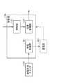
図1は、実施の形態1における分電盤を含む電力供給システムの構成を示す図である。(Embodiment 1)
FIG. 1 is a diagram showing a configuration of a power supply system including a distribution board in the first embodiment.
図1に示された電力供給システム10は、機器(通常負荷)124〜126および自立機器(非常用負荷)121〜123へ電力を供給する。以下に、図1に示された各構成要素を具体的に説明する。 The
分電盤100は、系統電源11と、太陽光発電パネル(PVパネル)13、燃料電池(FC)14、および蓄電池(SB)15等の電力供給装置とから供給される電力を建物に設けられる負荷(機器124〜126および自立機器121〜123)に供給する制御を行う分電盤である。特に、分電盤100は、系統電源11が電力を供給していない場合でも、自立機器121〜123のそれぞれへ電力を供給する。また、分電盤100は、図1に示すように主分電盤101、自立分電盤102、および自立切り替え器103を備えている。
主分電盤101は、分岐回路を有する分電盤であり、系統電源11、太陽光発電パネル13、燃料電池14、および蓄電池15から供給される電力を機器124〜126それぞれに供給する制御を行う。また、主分電盤101は、制御部104、蓄電部105、停電準備スイッチ106、ブレーカー134〜136、142、主幹ブレーカー141、リレー143、および変流器(CT)144を備えている。 The
自立分電盤102は、分岐回路を有する追加的な分電盤であり、自立切り替え器103から供給される電力を自立機器121〜123のそれぞれへ電力を供給する。すなわち、自立分電盤102は、太陽光発電パネル13、燃料電池14、および蓄電池15から供給される電力を自立機器121〜123のそれぞれへ電力を供給する。特に、自立分電盤102は、系統電源11が電力を供給していない場合でも、自立機器121〜123のそれぞれへ電力を供給する。また、自立分電盤102は、ブレーカー131〜133を備えている。 The independent distribution board 102 is an additional distribution board having a branch circuit, and supplies the electric power supplied from the independent switching device 103 to each of the
自立切り替え器103は、系統電源11および電力供給装置からの電力を供給するか、あるいは、電力供給装置からの電力だけを供給するかの切り替え器である。例えば、系統電源11が電力を供給している場合、系統電源11および電力供給装置からの電力が供給される。一方、系統電源11が電力を供給していない場合、電力供給装置からの電力だけが供給される。 The self-sustained switch 103 is a switch that supplies power from the
制御部104は、後述するように停電の検知および分電盤100の動作を制御する。 The
蓄電部105は、例えば蓄電池であり、系統電源11から供給される電力を充電する。そして、蓄電部105は、停電時に、分電盤100に含まれる各構成要素に電力を供給する。なお、蓄電部105は、停電時に、太陽光発電パネル13、燃料電池14、および蓄電池15から供給される電力を充電してもよい。 The
停電準備スイッチ106は、通常充電と停電準備充電とを切り替えるためのスイッチである。例えば、電力会社等からの情報により停電が予想される場合に、ユーザが停電準備スイッチ106をオンにすることにより、停電準備充電に切り替わる。 The power
リレー143は、スイッチの一種であり、電気信号によって電気回路の開閉を行う。具体的には、切替制御部153が、リレー143をオンまたはオフにする。リレー143は、オンにされた場合、接続状態を導通に切り替え、オフにされた場合、接続状態を非導通に切り替える。 The
ブレーカー131〜136、142、および、主幹ブレーカー141は、過電流または漏電等が検知された場合、回路を遮断する。変流器144は、主分電盤101における電流を測定するためのセンサである。 The
系統電源11は、電力会社が提供する電力供給システムである。太陽光発電パネル13および燃料電池14では、安定的かつ十分な電力が得られない場合がある。そのため、太陽光発電パネル13および燃料電池14が利用される場合でも、系統電源11が利用される。 The
パワーコンディショナー(PCS)12は、太陽光発電パネル13および燃料電池14から供給される電力を調整する。例えば、パワーコンディショナー12は、太陽光発電パネル13および燃料電池14から供給される電力を直流から交流に変換する。また、パワーコンディショナー12は、蓄電池15へ供給する電力、または、蓄電池15から供給される電力を調整する。例えば、パワーコンディショナー12は、蓄電池15へ供給する電力を交流から直流に、蓄電池15から供給される電力を直流から交流に変換する。さらに、パワーコンディショナー12は、変流器144によって測定された電流の状態に応じて、主分電盤101に電力を供給する。 The power conditioner (PCS) 12 adjusts the power supplied from the solar
太陽光発電パネル13は、ソーラーパネル、太陽電池パネルまたは太陽電池モジュールとも呼ばれ、太陽光を利用して発電する。例えば、太陽光発電パネル13は、パネル状に配置された複数の太陽電池で構成される。 The solar
燃料電池14は、燃料の化学反応を利用して発電する。例えば、燃料電池14は、水素と酸素とを反応させることによって発電する。 The
蓄電池15は、系統電源11、太陽光発電パネル13または燃料電池14から供給される電力を蓄積する。 The
自立コンセント111〜113は、電力供給システム10に自立機器121〜123を接続するためのインタフェースである。自立コンセント111〜113には、系統電源11から電力が供給されていない場合でも、太陽光発電パネル13等から電力が供給される。 The
コンセント114〜116は、電力供給システム10に機器124〜126を接続するためのインタフェースである。系統電源11から電力が供給されていない場合、コンセント114〜116には、どこからも電力が供給されない。 The
自立機器121〜123は、電力の供給を受けて動作する機器であり、例えば、電力が常に供給されるべき家電である。これらの代表的な例は、冷蔵庫である。 The self-supporting
機器124〜126は、電力の供給を受けて動作する機器であり、例えば、停止が許容される家電である。これらの代表的な例は、使用頻度の少ない部屋の照明機器である。 The
次に、制御部104の詳細な構成について説明する。図2は、実施の形態1における分電盤100の制御部104の詳細な構成を示すブロック図である。 Next, a detailed configuration of the
制御部104は、図2に示すように充電制御部151、検知部152、および切替制御部153を備えている。 As shown in FIG. 2, the
充電制御部151は、系統電源11から蓄電部105へ充電する際、蓄電部105の満充電時の総充電容量に対して低い所定の充電割合(第1割合)に蓄電部105への充電を抑制(制御)する通常充電と、蓄電部105への充電を総充電容量まで行う停電準備充電とを、切り替えて蓄電部105への充電を行う。また、充電制御部151は、停電準備スイッチ106がオンされた場合に、停電準備充電に切り替えて蓄電部105への充電を行い、停電準備スイッチ106がオフされた場合に、通常充電に切り替えて蓄電部105への充電を行う。 When charging the
検知部152は、系統電源11から電力が供給されない状態である停電を検知する。 The
切替制御部153は、検知部152で検知された情報に基づいて、リレー143および自立切り替え器103を制御する。 The switching
以下、系統電源11および電力供給装置からの電力を供給する場合、および、電力供給装置からの電力だけを供給する場合について、電力供給システム10の動作を具体的に説明する。 Hereinafter, the operation of the
まず、系統電源11および電力供給装置からの電力を供給する場合、系統電源11は、主分電盤101に電力を供給する。また、太陽光発電パネル13および燃料電池14も、パワーコンディショナー12を介して、主分電盤101に電力を供給する。さらに、主分電盤101から蓄電池15へ、または、蓄電池15から主分電盤101へ、電力がパワーコンディショナー12を介して供給される。 First, when supplying power from the
そして、主分電盤101は、機器124〜126に電力を供給する。また、主分電盤101は、自立切り替え器103を介して、自立分電盤102に電力を供給する。自立分電盤102は、自立機器121〜123に電力を供給する。 The
一方、電力供給装置からの電力だけを供給する場合、太陽光発電パネル13、燃料電池14、および蓄電池15は、主分電盤101に電力を供給しない。 On the other hand, when only the power from the power supply device is supplied, the solar
パワーコンディショナー12は、自立切り替え器103を介して自立分電盤102に電力を供給する。自立分電盤102は、自立機器121〜123に電力を供給する。 The
以上の構成および動作によって、電力供給システム10は、系統電源11が電力を供給している場合も、系統電源11が電力を供給していない場合も、自立機器121〜123に電力を供給することができる。 With the above configuration and operation, the
次に、上記のように構成された分電盤100において系統電源11から蓄電部105へ充電する際の動作について説明する。 Next, an operation when charging the
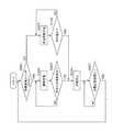
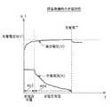
図3は、実施の形態1における系統電源11から蓄電部105へ充電する際の動作の流れを示すフローチャートである。また、図4Aおよび図4Bは、実施の形態1における充電特性を示す図であり、図4Aは通常充電における充電特性、図4Bは停電準備充電における充電特性を示す図である。 FIG. 3 is a flowchart showing a flow of operation when charging
充電制御部151は、停電準備スイッチ106がオフであるか否かを判定する(ステップS101)。この判定の結果、停電準備スイッチ106がオフである場合(ステップS101でYES)、充電制御部151は、蓄電部105の満充電時の総充電容量に対して低い所定の充電割合(第1割合)に蓄電部105への充電を抑制する通常充電で、蓄電部105への充電を行う(ステップS102)。充電制御部151は、総充電容量に対して低い所定の充電割合(例えば7割)に蓄電部105への充電を抑制するように、図4Aに示すように定電流充電401を行った後、充電電圧Aで定電圧充電402を行う。充電制御部151は、蓄電部105への充電が所定の充電割合(第1割合)になったか否かを判定する(ステップS103)。所定の充電割合になった場合(ステップS103でYES)、充電制御部151は、蓄電部105への充電を停止する(ステップS104)。所定の充電割合になっていない場合(ステップS103でNO)、充電制御部151は、通常充電で蓄電部105への充電を行う(ステップS102)。 The charging
一方、停電準備スイッチ106がオフでない、すなわちオンである場合(ステップS101でNO)、充電制御部151は、蓄電部105への充電を総充電容量まで行う停電準備充電で、蓄電部105への充電を行う(ステップS105)。充電制御部151は、充電の抑制を行わず、総充電容量まで充電を行うように、図4Bに示すように定電流充電403を行った後、充電電圧Bで定電圧充電404を行う。充電制御部151は、蓄電部105への充電が満充電になったか否かを判定する(ステップS106)。満充電になった場合(ステップS106でYES)、充電制御部151は、蓄電部105への充電を停止する(ステップS104)。満充電になっていない場合(ステップS106でNO)、充電制御部151は、停電準備充電で蓄電部105への充電を行う(ステップS105)。なお、ここでは、停電準備充電において、充電の抑制を行わず、総充電容量まで充電を行っているが、例えば、通常充電における所定の充電割合(第1割合:例えば7割)より大きい所定の充電割合(第2割合:例えば9割)に蓄電部105への充電を抑制しても構わない。 On the other hand, when the power
充電制御部151は、蓄電部105の充電容量が充電を必要とする所定の充電割合(例えば5割)まで低下したか否かを判定する(ステップS107)。この判定の結果、所定の充電割合まで低下している場合(ステップS107でYES)、停電準備スイッチ106がオフであるか否かの判定処理(ステップS101)に戻る。一方、所定の充電割合まで低下していない場合(ステップS107でNO)、所定の充電割合まで低下したか否かの判定処理(ステップS107)を繰り返す。 The charging
なお、本フローチャートでは、第1割合になっていない場合(ステップS103でNO)に、充電制御部151は、蓄電部105への充電が第1割合になるまで、通常充電で蓄電部105への充電を行っているが、これに限られるものではない。例えば、第1割合になっていない場合(ステップS103でNO)に、再度、停電準備スイッチ106がオフであるか否かの判定処理(ステップS101)に戻っても構わない。これにより、通常充電で蓄電部105へ充電を行っている途中に、停電準備スイッチ106がオンされた場合にも、充電制御部151は、停電準備充電に切り替えて蓄電部105への充電を行うことができる。 In this flowchart, when the first ratio is not reached (NO in step S103), the charging
次に、通常充電、停電準備充電、および自己放電のよる蓄電部105の充電容量の変化について説明する。 Next, changes in the charging capacity of
図5は、実施の形態1における通常充電、停電準備充電、および自己放電による充電容量の変化の一例を示す図である。 FIG. 5 is a diagram showing an example of changes in charge capacity due to normal charging, power failure preparation charging, and self-discharge in the first embodiment.
図5では、充電区間501において、通常充電により第1割合である充電容量bまで蓄電部105への充電が行われると、充電制御部151は蓄電部105への充電を停止する。そして、充電を行っていない待機区間502において、蓄電部105は自己放電し、充電容量が低下し、充電を必要とする所定の充電割合である充電容量cまで低下すると、充電制御部151は通常充電により蓄電部105への充電を開始する。次に、充電区間503において、通常充電により蓄電部105への充電が行われているときに、停電準備スイッチ106がオンにされると、充電区間504において、充電制御部151は、蓄電部105への充電を総充電容量まで行う停電準備充電で、蓄電部105への充電を行う。充電区間504において、停電準備充電により総充電容量である充電容量aまで蓄電部105への充電が行われると、充電制御部151は蓄電部105への充電を停止する。そして、充電を行っていない待機区間505において、蓄電部105は自己放電する。ここで、停電準備スイッチ106がオフにされたとする。待機区間505において、充電容量が低下し、充電を必要とする所定の充電割合である充電容量cまで低下すると、充電制御部151は通常充電により蓄電部105への充電を開始する。また、充電区間506において、通常充電により充電容量bまで蓄電部105への充電が行われると、充電制御部151は蓄電部105への充電を停止する。そして、充電を行っていない待機区間507において、蓄電部105は自己放電することになる。 In FIG. 5, when charging of the
以上のように、分電盤に蓄電部を備えているので、系統電源から電力が供給されない停電時において、分電盤を動作させるための電力を充分に確保することができる。また、所定の充電割合に蓄電部105への充電を抑制する通常充電と、充電の抑制を行わず、総充電容量まで充電を行う停電準備充電とを、必要に応じて切り替えることにより、蓄電部105の性能および寿命が劣化するのを防止するとともに、必要時には分電盤を動作させるための電力を充分に確保することができる。 As described above, since the power distribution unit is provided in the distribution board, it is possible to sufficiently secure power for operating the distribution board during a power failure when power is not supplied from the system power supply. In addition, the power storage unit can be switched by switching between normal charging that suppresses charging to the
なお、本実施の形態では、停電準備スイッチ106のオンオフをユーザが操作する構成としているが、これに限られるものではない。例えば、ユーザにより停電準備スイッチ106がオンされることで、充電制御部151が停電準備充電で蓄電部105への充電を行って、蓄電部105への充電が完了した場合、充電制御部151が停電準備スイッチ106をオフにする構成としても構わない。これにより、ユーザが停電準備スイッチ106をオフにする、すなわち通常充電に戻すことを忘れることを防止することができる。 In the present embodiment, the user operates to turn on / off the power
また、充電制御部151が、蓄電部105の故障および寿命レベル等を判定し、故障または所定の寿命レベルに達した場合等に、例えばアラーム等を鳴らすように構成しても構わない。 Further, the charging
更には、再び充電を開始する蓄電池容量cを、停電準備スイッチ106のオンオフに応じて異なる値としてもよい。例えば、停電準備スイッチ106がオフとオンのときに再び充電を開始する蓄電池容量を、それぞれcとc’とすると、c<c’<bを満たすように値を設定してもよい。 Furthermore, the storage battery capacity c at which charging is started again may be set to a different value depending on whether the power
(実施の形態2)
実施の形態1では、充電制御部は、停電準備スイッチ106のオンオフに応じて通常充電と停電準備充電との切り替えを行っているのに対して、本実施の形態2では、停電準備スイッチ106のオンオフに加え、電力会社等からの停電情報に応じて通常充電と停電準備充電との切り替えを行っている。ここで、本実施の形態2における分電盤の構成は図1に示す実施の形態1と同様であり、制御部104の構成が制御部200の構成となる。(Embodiment 2)
In the first embodiment, the charging control unit switches between normal charging and power failure preparation charging in accordance with the on / off state of the power
図6は、実施の形態2における分電盤の制御部200の詳細な構成を示すブロック図である。なお、実施の形態1と同様の構成については、同じ符号を付し、説明を省略する。 FIG. 6 is a block diagram showing a detailed configuration of
制御部200は、図6に示すように停電情報取得部201、充電制御部202、検知部152、および切替制御部153を備えている。 As illustrated in FIG. 6, the
停電情報取得部201は、ネットワークを介して例えば電力会社等から停電の予定を示す停電情報を取得する。 The power outage
充電制御部202は、系統電源11から蓄電部105へ充電する際、蓄電部105の満充電時の総充電容量に対して低い所定の充電割合(第1割合)に蓄電部105への充電を抑制する通常充電と、蓄電部105への充電を総充電容量まで行う停電準備充電とを、切り替えて蓄電部105への充電を行う。また、充電制御部202は、停電準備スイッチ106がオンされた場合に、停電準備充電に切り替えて蓄電部105への充電を行い、停電準備スイッチ106がオフされた場合に、通常充電に切り替えて蓄電部105への充電を行う。さらに、充電制御部202は、停電情報取得部201によって停電情報が取得された場合に、停電準備充電に切り替えて蓄電部105への充電を行い、停電情報取得部201によって停電情報が取得されていない場合に、通常充電に切り替えて蓄電部105への充電を行う。 When charging the
図7は、実施の形態2における系統電源11から蓄電部105へ充電する際の動作の流れを示すフローチャートである。 FIG. 7 is a flowchart showing an operation flow when charging
充電制御部202は、停電準備スイッチ106がオフであるか否かを判定する(ステップS101)。この判定の結果、停電準備スイッチ106がオフである場合(ステップS101でYES)、充電制御部202は、停電情報取得部201によって停電情報が取得されているか否かを判定する(ステップS201)。この判定の結果、停電情報が取得されていない場合(ステップS201でNO)、充電制御部202は、蓄電部105の満充電時の総充電容量に対して低い所定の充電割合(第1割合)に蓄電部105への充電を抑制する通常充電で、蓄電部105への充電を行う(ステップS102)。 The charging
一方、停電準備スイッチ106がオフでない、すなわちオンである場合(ステップS101でNO)および停電情報取得部201によって停電情報が取得されている場合(ステップS201でYES)、充電制御部202は、蓄電部105への充電を総充電容量まで行う停電準備充電で、蓄電部105への充電を行う(ステップS105)。 On the other hand, when power
通常充電および停電準備充電を行った場合ともに、以降の処理は上記実施の形態1と同様である。 In both cases of normal charging and power failure preparation charging, the subsequent processing is the same as in the first embodiment.
以上のように、停電情報を取得しているので、ユーザにより停電準備スイッチ106のオンオフが操作されなくても、所定の充電割合に蓄電部105への充電を抑制する通常充電と、充電の抑制を行わず、総充電容量まで充電を行う停電準備充電とを、必要に応じて切り替えることにより、蓄電部105の性能および寿命が劣化するのを防止するとともに、必要時には分電盤を動作させるための電力を充分に確保することができる。 As described above, since the power failure information is acquired, even if the user does not operate the power
なお、本実施の形態では、ユーザがオンオフを操作する停電準備スイッチ106を備える構成としているが、これに限られるものではない。例えば、停電準備スイッチ106を備えない構成としても構わない。 In addition, in this Embodiment, although it is set as the structure provided with the power
また、本実施の形態では、停電情報取得部201が、ネットワークを介して例えば電力会社等から停電の予定を示す停電情報を取得する構成としているが、これに限られるものではない。例えば、停電情報取得部201が台風シーズン等のカレンダ情報を取得し、充電制御部202が台風シーズンには停電準備充電を行い、台風シーズン以外には通常充電を行うように制御しても構わない。また、例えば、停電情報取得部201が雷や大雨などの警報もしくは注意報の情報を取得し、雷や大雨などの警報もしくは注意報が発令されていれば充電制御部202が停電準備充電を行い、警報および注意報が発令されていなければ通常充電を行うように制御しても構わない。 Moreover, in this Embodiment, although the power failure
(実施の形態3)
本実施の形態では、図1に示す分電盤100の主分電盤101の蓄電部105の構成について説明する。(Embodiment 3)
In the present embodiment, the configuration of
図8Aおよび図8Bは、実施の形態3における主分電盤101の外観構成を示す斜視図であり、図8Aは2つの蓄電池(蓄電池パック)を収容した状態、図8Bは1つの蓄電池(蓄電池パック)を取り出した状態を示す図である。なお、実施の形態1と同様の構成については、同じ符号を付し、説明を省略する。 8A and 8B are perspective views showing an external configuration of
蓄電部105は、図8Aに示すようにパック収納部165に収納された2つの蓄電池(蓄電池パック)により構成されている。また、蓄電部105は、図8Bに示すように1つの蓄電池(蓄電池パック)161aは主分電盤101より着脱可能に設けられる。 The
蓄電池161aには、例えばUSB端子等の端子162が設けられている。 The
主分電盤101には、接続端子160が設けられており、蓄電池161aの接続端子(図示せず)と接続されることにより、系統電源11から蓄電部105への充電が行われる。 The
このように構成されることによって、停電時等において、蓄電池161aを主分電盤101より取り外して、必要な場所に持っていくことが可能になる。そして、例えばUSBケーブル等のケーブル301を介して例えばスマートフォン、タブレット端末等の携帯機器300に充電を行うことが可能である。 By being configured in this way, it becomes possible to remove the
(実施の形態4)
図9は、実施の形態4における分電盤を含む電力供給システムの構成を示す図である。なお、図1に示す実施の形態1と同様の構成については、同じ符号を付し、説明を省略する。(Embodiment 4)
FIG. 9 is a diagram showing a configuration of a power supply system including a distribution board in the fourth embodiment. In addition, about the structure similar to
図9に示された電力供給システム20は、機器124〜126および自立機器121〜123へ電力を供給する。以下に、図9に示された各構成要素を具体的に説明する。 The
分電盤400は、系統電源11から供給される電力を建物に設けられる負荷(機器124〜126および自立機器121〜123)に供給する制御を行う分電盤である。また、分電盤400は、系統電源11が電力を供給していない場合に、蓄電部(蓄電池パック)から供給される電力を自立機器121〜123のそれぞれへ電力を供給する。また、分電盤400は、図9に示すように主分電盤401、自立分電盤402、および自立切り替え器403を備えている。 The
主分電盤401は、分岐回路を有する分電盤であり、系統電源11から供給される電力を機器124〜126それぞれに供給する制御を行う。また、主分電盤401は、制御部404、蓄電部405、モードスイッチ406、ブレーカー134〜136、および主幹ブレーカー141を備えている。 The
自立分電盤402は、分岐回路を有する追加的な分電盤であり、自立切り替え器403から供給される電力を自立機器121〜123のそれぞれへ電力を供給する。すなわち、自立分電盤402は、系統電源11から供給される電力または蓄電部(蓄電池パック)から供給される電力を自立機器121〜123のそれぞれへ電力を供給する。特に、自立分電盤402は、系統電源11が電力を供給していない場合でも、自立機器121〜123のそれぞれへ電力を供給する。また、自立分電盤402は、ブレーカー131〜133を備えている。 The
自立切り替え器403は、系統電源11からの電力を供給する(系統連携モード)か、あるいは、蓄電部(蓄電池パック)からの電力を供給する(自立運転モード)かの切り替え器である。例えば、系統電源11が電力を供給している場合、系統電源11からの電力が供給される。一方、系統電源11が電力を供給していない場合、蓄電部(蓄電池パック)からの電力が供給される。 The self-
制御部404は、後述するように外部からの信号の取得、停電の検知および分電盤400の動作を制御する。 The
モードスイッチ406は、系統連携モードおよび自立運転モードのいずれかを手動で選択するためのスイッチである。 The
蓄電部405は、例えば実施の形態3の図8Aに示したようにパック収納部165に収納された2つの蓄電池(蓄電池パック)161により構成されている。パック収納部165は、蓄電池パック161の接続端子(図示せず)との接続および接続解除が自在な接続部(図8Bに示す接続端子160)を有している。パック収納部165に蓄電池パック161が収納され、パック収納部165の接続端子160と蓄電池パック161の接続端子とが接続されることにより、系統電源11から蓄電部405(蓄電池パック161)への充電、および蓄電部405(蓄電池パック161)からの電力供給が行われる。なお、蓄電池(蓄電池パック)は、2つの限られるものではなく、例えば、3つ以上で構成されても構わない。 The
また、蓄電池パック161は、当該蓄電池パックの残存電力量を示す表示部(図8Bでは図示せず)を備えており、パック収納部165へは、接続端子160に接続された状態で、表示部が視認可能となる向きに収納される。 In addition, the
図10は、実施の形態4における蓄電池パック161の詳細な構成を示すブロック図である。 FIG. 10 is a block diagram showing a detailed configuration of
また、蓄電池パック161は、図10に示すように、1以上の蓄電池171、接続端子部172、充電回路部173、放電回路部174、電力供給部175、表示制御部176、および表示部177を備えている。 Further, as shown in FIG. 10, the
蓄電池171は、供給される電力を蓄積するとともに、蓄積した電力を放電する。 The
接続端子部172は、分電盤400に対して機械的および電気的な接続と接続解除とが自在であり、電力を充放電するための接続端子である。 The
充電回路部173は、接続端子部172を介して入力される系統電源11の電力を用いて蓄電池171を充電する。 The charging
放電回路部174は、蓄電池171から放電される電力を出力する。 The
電力供給部175は、例えば図8Bに示す携帯機器300等の他の機器と電気的に接続されることにより、放電回路部174から出力される電力を他の機器に出力する。具体的には、電力供給部175は、例えば図8Bに示すUSB端子(USBポート)等の端子162として構成される。 The
表示制御部176は、蓄電池171の残存電力量を取得し、表示部177に残存電力量を表示する。 The
表示部177は、例えば液晶表示装置(LCD(Liquid Crystal Display))、LED(Light Emitting Diode)表示等であり、蓄電池パック161(蓄電池171)の残存電力量を表示するために用いられる。 The
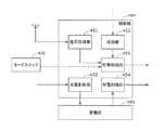
次に、制御部404の詳細な構成について説明する。図11は、実施の形態4における分電盤400の制御部404の詳細な構成を示すブロック図である。 Next, a detailed configuration of the
制御部404は、図11に示すように、信号取得部451、検知部452、充電制御部453、放電制御部454、および切替制御部455を備えている。 As shown in FIG. 11, the
信号取得部451は、例えば系統連携モードおよび自立運転モードのいずれのモードを選択するかを示す制御信号、および電力を抑制することを求める電力抑制信号等の外部からの信号を取得する。 The
検知部452は、系統電源11から電力が供給されない状態である停電を検知する。 The
充電制御部453は、系統電源から供給される交流電力を直流電力に変換し、直流電力を蓄電部405に供給して蓄電部405を充電する。すなわち、充電制御部453は、蓄電池パック161を充電する。具体的には、充電制御部453は、AC/DCコンバータを含んで構成される。
また、充電制御部453は、蓄電池パックと通信して蓄電池パックの残存電力量に関する情報を取得する。そして、充電制御部453は、系統連携モード時に、残存電力量が所定の閾値を下回っている場合、系統電源から供給される電力を蓄電池パックに供給して蓄電池パックを充電する。また、充電制御部453は、系統連携モード時に、残存電力量が所定の閾値以上である場合は、系統電源から供給される電力を蓄電池パックに供給しない。 In addition, the charging
放電制御部454は、蓄電部405から供給される直流電力を交流電力に変換し、自立切り替え器403に供給する。具体的には、放電制御部454は、DC/ACインバータを含んで構成される。 The
切替制御部455は、検知部452で検知された情報に基づいて、自立切り替え器103を制御し、系統連携モードと自立運転モードとを切り替える。すなわち、切替制御部455は、検知部452によって系統電源から電力が供給されていること(停電でないこと)が検知されている(停電でない)場合には系統連携モードを選択し、系統電源から電力が供給されていないこと(停電であること)が検知されている場合には自立運転モードを選択する。 The switching
また、切替制御部455は、モードスイッチ406によって選択されたモードに従って自立切り替え器103を制御し、系統連携モードと自立運転モードとを切り替える。 In addition, the switching
さらに、切替制御部455は、信号取得部451で取得された信号に基づいて、自立切り替え器103を制御し、系統連携モードと自立運転モードとを切り替える。例えば、信号取得部451で取得された信号が系統連携モードおよび自立運転モードのいずれのモードを選択するかを示す制御信号である場合、切替制御部455は、制御信号が示すモードに従って自立切り替え器103を制御し、系統連携モードと自立運転モードとを切り替える。また、信号取得部451で取得された信号が電力抑制信号である場合、切替制御部455は、自立切り替え器103を制御し、系統連携モードから自立運転モードへ切り替える。 Furthermore, the switching
また、切替制御部455は、自立運転モード時において、複数の蓄電池パックから自立機器(非常用負荷)に電力が供給されている期間中に複数の蓄電池パックの少なくとも1つが取り外された場合、残りの蓄電池パックを用いて自立機器への電力供給を継続する。 In addition, the switching
以下、系統電源11からの電力を供給する(系統連携モード)場合、および、蓄電部405(蓄電池パック)からの電力を供給する(自立運転モード)場合について、電力供給システム20の動作を具体的に説明する。 Hereinafter, the operation of the
まず、系統連携モードの場合、系統電源11は、主分電盤401に電力を供給する。そして、主分電盤401は、機器124〜126に電力を供給する。また、主分電盤401は、自立切り替え器403を介して、自立分電盤402に電力を供給する。自立分電盤402は、自立機器121〜123に電力を供給する。 First, in the system linkage mode, the
一方、自立運転モードの場合、蓄電部405(蓄電池パック)は、主分電盤101に電力を供給しない。蓄電部405(蓄電池パック)は、自立切り替え器103を介して自立分電盤102に電力を供給する。自立分電盤102は、自立機器121〜123に電力を供給する。 On the other hand, in the self-sustained operation mode, power storage unit 405 (storage battery pack) does not supply power to
以上のように、分電盤400に蓄電部405(蓄電池パック)を備えているので、電力供給システム20は、系統連携モードであっても、自立運転モードであっても、自立機器121〜123に電力を供給することができる。 As described above, since the electricity distribution unit 405 (storage battery pack) is provided in the
なお、本実施の形態では、充電制御部453と放電制御部454とを分けて構成しているが、これに限られるものではなく、一体として構成しても構わない。この場合、具体的には、交流電力から直流電力に変換、および直流電力から交流電力に変換する双方向コンバータを含んで構成される。 In the present embodiment, the
以上、一つまたは複数の態様に係る分電盤および蓄電池パックについて、実施の形態に基づいて説明したが、本発明は、この実施の形態に限定されるものではない。本発明の趣旨を逸脱しない限り、当業者が思いつく各種変形を本実施の形態に施したものや、異なる実施の形態における構成要素を組み合わせて構築される形態も、一つまたは複数の態様の範囲内に含まれてもよい。 As mentioned above, although the distribution board and storage battery pack which concern on one or several aspects were demonstrated based on embodiment, this invention is not limited to this embodiment. Unless it deviates from the gist of the present invention, various modifications conceived by those skilled in the art have been made in this embodiment, and forms constructed by combining components in different embodiments are also within the scope of one or more aspects. May be included.
本発明は、系統電源から電力が供給されない停電時において、分電盤を動作させるための電力を充分に確保し、確保した電力の利用用途を広げることができ、分電盤、蓄電池パック、分電盤を含む電力供給システム、および、分電盤を含む住宅設備等に用いるのに有用である。 The present invention can secure sufficient power for operating the distribution board in the event of a power failure when power is not supplied from the system power supply, and can expand the usage of the secured power. It is useful for use in a power supply system including a switchboard, and a housing facility including a distribution board.
10、20 電力供給システム
11 系統電源
12 パワーコンディショナー(PCS)
13 太陽光発電パネル(PVパネル)
14 燃料電池(FC)
15 蓄電池(SB)
100、400 分電盤
101、401 主分電盤
102、402 自立分電盤
103、403 自立切り替え器
104、200、404 制御部
105、405 蓄電部
106 停電準備スイッチ
111、112、113 自立コンセント
114、115、116 コンセント
121、122、123 自立機器
124、125、126 機器
131、132、133、134、135、136、142 ブレーカー
141 主幹ブレーカー
143 リレー
144 変流器(CT)
151、202、453 充電制御部
152、452 検知部
153、455 切替制御部
160 接続端子
161、161a、161b 蓄電池(蓄電池パック)
162 端子
165 パック収納部
171 蓄電池
172 接続端子部
173 充電回路部
174 放電回路部
175 電力供給部
176 表示制御部
177 表示部
201 停電情報取得部
300 携帯機器
301 ケーブル
406 モードスイッチ
451 信号取得部
454 放電制御部10, 20
13 Solar power generation panel (PV panel)
14 Fuel cell (FC)
15 Storage battery (SB)
100, 400
151, 202, 453
162
本発明は、系統電源から供給される電力を建物に設けられる負荷に供給する制御を行う蓄電システムおよび蓄電システムの制御方法に関する。The present invention relates to a powerstorage system that performs control to supply power supplied from a system power supply to a load provided in a building, and a control method for thepower storage system .
本発明の一態様に係る蓄電システムは、1以上の蓄電池を備える蓄電部と、外部からの信号を取得する信号取得部と、系統電源から供給された交流電力を直流電力に変換し、当該直流電力を前記蓄電池に供給して当該蓄電池を充電する充電制御部と、系統電源から供給された交流電力を負荷に供給する第1のモードと、前記蓄電池に充電されている電力を用いて、前記負荷に電力を供給する第2のモードとを、前記信号取得部によって取得された前記信号に応じて切り替える切替制御部とを備える。Apower storage system according to one embodiment of the present invention converts a power storage unit including one or more storage batteries, a signal acquisition unit that acquires a signal from the outside, and AC power supplied from a system power supply into DC power, and Using the charge control unit for supplying power to the storage battery to charge the storage battery, the first mode for supplying AC power supplied from a system power supply to the load, and the power charged in the storage battery, A switching control unit configured to switch a second mode for supplying power to the load according to the signal acquired by the signal acquisition unit.
Claims (12)
Translated fromJapanese外部からの信号を取得する信号取得部と、
系統電源から供給された交流電力を直流電力に変換し、当該直流電力を前記蓄電池に供給して当該蓄電池を充電する充電制御部と、
系統電源から供給された交流電力を負荷に供給する第1のモードと、前記蓄電池に充電されている電力を用いて、前記負荷に電力を供給する第2のモードとを、前記信号取得部によって取得された前記信号に応じて切り替える切替制御部とを備える
切替装置。A power storage unit comprising one or more storage batteries;
A signal acquisition unit for acquiring an external signal;
AC power supplied from a system power source is converted to DC power, and the DC power is supplied to the storage battery to charge the storage battery; and
A first mode for supplying AC power supplied from a system power source to a load and a second mode for supplying power to the load using the power charged in the storage battery by the signal acquisition unit. A switching device comprising: a switching control unit that switches according to the acquired signal.
前記切替制御部が前記第2のモードに切り替えているときは、前記蓄電池の放電電力を、前記放電制御部を介して前記負荷に供給する
請求項1に記載の切替装置。A discharge control unit for converting the DC power of the storage battery into AC power;
The switching device according to claim 1, wherein when the switching control unit is switching to the second mode, the discharge power of the storage battery is supplied to the load via the discharge control unit.
前記切替制御部は、前記制御信号が示すモードに従って、前記第1のモードおよび前記第2のモードを切り替える
請求項1または2に記載の切替装置。The signal acquired by the signal acquisition unit is a control signal indicating which mode of the first mode and the second mode is selected,
The switching device according to claim 1, wherein the switching control unit switches between the first mode and the second mode according to a mode indicated by the control signal.
前記切替制御部は、前記信号取得部によって前記電力抑制信号が取得されると、前記第1のモードから前記第2のモードに切り替える
請求項1または2に記載の切替装置。The signal acquired by the signal acquisition unit is a power suppression signal that seeks to suppress power,
The switching device according to claim 1, wherein the switching control unit switches from the first mode to the second mode when the power suppression signal is acquired by the signal acquisition unit.
請求項1−4のいずれか1項に記載の切替装置。In the first mode, when the remaining power amount of the storage battery is below a predetermined threshold, the charge control unit supplies the storage battery with power supplied from the system power supply to charge the storage battery, 5. The switching device according to claim 1, wherein when the remaining power amount is equal to or greater than the predetermined threshold, the power supplied from the system power supply is not supplied to the storage battery.
前記系統電源から電力が供給されているか否かを検知する検知部を備え、
前記切替制御部は、前記検知部によって前記系統電源から電力が供給されていることが検知されている場合には前記第1のモードを選択し、前記検知部によって前記系統電源から電力が供給されていないことが検知されている場合には前記第2のモードを選択する
請求項1に記載の切替装置。further,
A detection unit that detects whether or not power is supplied from the system power supply,
The switching control unit selects the first mode when the detection unit detects that power is supplied from the system power supply, and the detection unit supplies power from the system power supply. The switching device according to claim 1, wherein the second mode is selected when it is detected that the error has not occurred.
前記第1のモードおよび前記第2のモードのいずれかを選択するためのモードスイッチを備え、
前記切替制御部は、前記モードスイッチによって選択されたモードに従って、前記第1のモードおよび前記第2のモードを切り替える
請求項1に記載の切替装置。further,
A mode switch for selecting one of the first mode and the second mode;
The switching device according to claim 1, wherein the switching control unit switches the first mode and the second mode according to a mode selected by the mode switch.
前記蓄電池パックの接続端子部との接続および接続解除が自在な接続部と、
前記接続部が設けられ、かつ、前記蓄電池パックを収納するパック収納部と、を備える
請求項1−7のいずれか1項に記載の切替装置。The storage battery is a storage battery pack,
A connection part that can be freely connected to and disconnected from the connection terminal part of the storage battery pack, and
The switching device according to claim 1, further comprising: a pack storage unit provided with the connection unit and storing the storage battery pack.
前記パック収納部は、前記接続部に接続された前記蓄電池パックの前記表示部が視認可能となる向きに前記蓄電池パックを収納する
請求項8に記載の切替装置。The storage battery pack includes a display unit indicating a remaining power amount of the storage battery pack,
The switching device according to claim 8, wherein the pack storage unit stores the storage battery pack in a direction in which the display unit of the storage battery pack connected to the connection unit is visible.
複数の前記接続部のそれぞれに複数の前記蓄電池パックのそれぞれが接続される
請求項8または9に記載の切替装置。A plurality of the connecting portions;
The switching device according to claim 8 or 9, wherein each of the plurality of storage battery packs is connected to each of the plurality of connection portions.
請求項10に記載の切替装置。When at least one of the plurality of storage battery packs is removed during a period in which power is supplied to the load from the plurality of storage battery packs, the switching control unit uses the remaining storage battery pack to supply power to the load. The switching device according to claim 10, wherein the supply is continued.
系統電源から供給される交流電力を直流電力に変換し、当該直流電力を蓄電池に供給して当該蓄電池を充電する充電ステップと、
系統電源から供給された交流電力を負荷に供給する第1のモードと、前記蓄電池に充電されている電力を用いて、前記負荷に電力を供給する第2のモードとを、前記取得ステップにおいて取得された前記信号に応じて切り替える切替ステップと、を含む
切替装置の制御方法。An acquisition step of acquiring an external signal;
A charging step of converting AC power supplied from a system power source into DC power, supplying the DC power to a storage battery, and charging the storage battery;
In the acquisition step, a first mode in which AC power supplied from a system power supply is supplied to the load and a second mode in which power is supplied to the load using the power charged in the storage battery are acquired in the acquisition step. A switching step of switching according to the received signal.
Applications Claiming Priority (2)
| Application Number | Priority Date | Filing Date | Title |
|---|---|---|---|
| JP2012240938 | 2012-10-31 | ||
| JP2012240938 | 2012-10-31 |
Related Parent Applications (1)
| Application Number | Title | Priority Date | Filing Date |
|---|---|---|---|
| JP2014505304ADivisionJPWO2014068874A1 (en) | 2012-10-31 | 2013-10-15 | Distribution board and battery pack |
Publications (1)
| Publication Number | Publication Date |
|---|---|
| JP2017112833Atrue JP2017112833A (en) | 2017-06-22 |
Family
ID=50626826
Family Applications (4)
| Application Number | Title | Priority Date | Filing Date |
|---|---|---|---|
| JP2014505304APendingJPWO2014068874A1 (en) | 2012-10-31 | 2013-10-15 | Distribution board and battery pack |
| JP2014041076AActiveJP5867528B2 (en) | 2012-10-31 | 2014-03-03 | Distribution board and battery pack |
| JP2014041075AActiveJP5866494B2 (en) | 2012-10-31 | 2014-03-03 | Distribution board and battery pack |
| JP2017029513APendingJP2017112833A (en) | 2012-10-31 | 2017-02-20 | Storage system and storage system control method |
Family Applications Before (3)
| Application Number | Title | Priority Date | Filing Date |
|---|---|---|---|
| JP2014505304APendingJPWO2014068874A1 (en) | 2012-10-31 | 2013-10-15 | Distribution board and battery pack |
| JP2014041076AActiveJP5867528B2 (en) | 2012-10-31 | 2014-03-03 | Distribution board and battery pack |
| JP2014041075AActiveJP5866494B2 (en) | 2012-10-31 | 2014-03-03 | Distribution board and battery pack |
Country Status (4)
| Country | Link |
|---|---|
| US (3) | US9680334B2 (en) |
| JP (4) | JPWO2014068874A1 (en) |
| CN (2) | CN106992586B (en) |
| WO (1) | WO2014068874A1 (en) |
Families Citing this family (23)
| Publication number | Priority date | Publication date | Assignee | Title |
|---|---|---|---|---|
| JP5968719B2 (en)* | 2012-08-06 | 2016-08-10 | 京セラ株式会社 | Management system, management method, control device, and storage battery device |
| US10148088B2 (en)* | 2014-08-06 | 2018-12-04 | Philips Lighting Holding B.V. | Power distribution system |
| USD795804S1 (en) | 2015-01-05 | 2017-08-29 | Schneider Electric It Corporation | Uninterruptible power supply and mobile power bank |
| US9793729B2 (en)* | 2015-01-05 | 2017-10-17 | Schneider Electric It Corporation | Uninterruptible power supply having removable battery |
| US20180041824A1 (en)* | 2015-02-25 | 2018-02-08 | Kyocera Corporation | Power converting apparatus, distribution board, and operation switching method |
| WO2016155707A1 (en)* | 2015-03-30 | 2016-10-06 | sonnen GmbH | Energy supply system, setup method for setting up same, and energy supply method |
| US10566820B2 (en) | 2015-05-18 | 2020-02-18 | Sharp Kabushiki Kaisha | Control system, control device, server, and control method |
| JP5984229B1 (en)* | 2015-07-21 | 2016-09-06 | 享史 中村 | Repair request system with means for confirming that supply is stopped |
| JP6868792B2 (en)* | 2015-07-31 | 2021-05-12 | テンパール工業株式会社 | Distribution board |
| JP2017108482A (en)* | 2015-12-07 | 2017-06-15 | 日東工業株式会社 | Power distribution board system |
| US10348092B1 (en)* | 2016-01-19 | 2019-07-09 | Noel Diaz | Electrical power distribution control device |
| KR102564469B1 (en)* | 2016-04-14 | 2023-08-08 | 삼성전자주식회사 | Method and apparatus for protecting a battery |
| GB2554357A (en)* | 2016-09-21 | 2018-04-04 | Hager Engineering Ltd | Locking device for locking a switching cabinet |
| JP6778929B2 (en)* | 2017-02-24 | 2020-11-04 | パナソニックIpマネジメント株式会社 | Power storage system |
| JP6621892B2 (en)* | 2018-10-04 | 2019-12-18 | シャープ株式会社 | Control device, charge / discharge control system, and control method |
| US20220190615A1 (en)* | 2019-03-19 | 2022-06-16 | Microgreen Solar Inc. | Apparatus, system, and method for providing power |
| CN110876617B (en)* | 2019-08-28 | 2023-06-16 | 深圳市永康达电子科技有限公司 | Charging system of cardiovascular measuring device |
| KR102483972B1 (en)* | 2020-11-13 | 2023-01-03 | (주)에너캠프 | Charging and discharging control method of a power station equipped with multiple battery packs |
| US11817701B2 (en) | 2021-01-29 | 2023-11-14 | Eaton Intelligent Power Limited | Multi-port split-phase power system |
| US11495993B1 (en)* | 2021-05-11 | 2022-11-08 | Kitu Systems, Inc. | System and method for facilitating autonomous operation of a smart energy device |
| JP2024016572A (en)* | 2022-07-26 | 2024-02-07 | 株式会社東芝 | Power supplies, energy management systems and power systems |
| US12224594B2 (en) | 2022-07-29 | 2025-02-11 | Enphase Energy, Inc. | Portable energy system with ac input |
| KR102617698B1 (en)* | 2023-03-29 | 2023-12-27 | 유호전기공업주식회사 | Gas Insulated Switchgear with embedded rechargeable DC power supply |
Citations (7)
| Publication number | Priority date | Publication date | Assignee | Title |
|---|---|---|---|---|
| JP2002369380A (en)* | 2001-06-01 | 2002-12-20 | Osaka Gas Co Ltd | Power supply system and method for accounting power charge for the supply |
| US20050121979A1 (en)* | 2003-12-09 | 2005-06-09 | Matsushita Electric Industrial Co., Ltd. | Direct-current uninterruptible power source unit |
| JP2006254537A (en)* | 2005-03-08 | 2006-09-21 | Honda Motor Co Ltd | Power supply |
| JP2009089572A (en)* | 2007-10-03 | 2009-04-23 | Tdk-Lambda Corp | Backup power supply system |
| JP2009201275A (en)* | 2008-02-22 | 2009-09-03 | Okamura Corp | Portable power supply device |
| JP2010115008A (en)* | 2008-11-06 | 2010-05-20 | Tdk-Lambda Corp | Uninterruptible power supply apparatus |
| JP3171974U (en)* | 2011-09-14 | 2011-11-24 | 株式会社タカラレーベン | Power storage system |
Family Cites Families (33)
| Publication number | Priority date | Publication date | Assignee | Title |
|---|---|---|---|---|
| JP2701340B2 (en) | 1988-07-27 | 1998-01-21 | スズキ株式会社 | Regenerative braking control circuit for electric vehicles |
| JPH0241603U (en)* | 1988-09-14 | 1990-03-22 | ||
| JPH10285825A (en)* | 1997-03-31 | 1998-10-23 | Sumitomo Electric Ind Ltd | Power supply system |
| JP2001258176A (en) | 2000-03-13 | 2001-09-21 | Sanyo Electric Co Ltd | Power consumption control system |
| US7602073B2 (en)* | 2002-11-15 | 2009-10-13 | Sprint Communications Company L.P. | Power system with fuel cell and localized air-conditioning for computing equipment |
| JP4044501B2 (en)* | 2003-09-17 | 2008-02-06 | セイコーインスツル株式会社 | Charge / discharge control circuit and rechargeable power supply |
| US7339353B1 (en)* | 2004-03-10 | 2008-03-04 | Quallion Llc | Power system for managing power from multiple power sources |
| JP4160919B2 (en)* | 2004-03-24 | 2008-10-08 | シャープ株式会社 | Inverter device |
| JP4312160B2 (en)* | 2005-01-14 | 2009-08-12 | 三洋電機株式会社 | Uninterruptible power system |
| JP2007043802A (en)* | 2005-08-02 | 2007-02-15 | Tokyo Electric Power Co Inc:The | Uninterruptible power supply and distribution board |
| US8872474B2 (en)* | 2006-02-09 | 2014-10-28 | Karl F. Scheucher | Fail safe serviceable high voltage battery pack |
| JP4868883B2 (en) | 2006-02-23 | 2012-02-01 | Jx日鉱日石エネルギー株式会社 | Emergency power supply system using fuel cell and distribution board |
| JP2008022650A (en) | 2006-07-13 | 2008-01-31 | Univ Of Tsukuba | Self-sustained operation support device and power supply system |
| JP4850019B2 (en) | 2006-10-16 | 2012-01-11 | 東京瓦斯株式会社 | Storage battery equipment in private power generation equipment connected to power system and operation method of storage battery equipment |
| US8909273B2 (en)* | 2009-05-25 | 2014-12-09 | Sharp Kabushiki Kaisha | Wireless communication system, wireless communication method, terminal apparatus, and communication apparatus |
| JP5330941B2 (en)* | 2009-09-15 | 2013-10-30 | パナソニック株式会社 | Equipment control system |
| US9154000B2 (en)* | 2009-09-25 | 2015-10-06 | Toshiba Mitsubishi-Electric Industrial Systems Corporation | Uninterruptible power supply apparatus including a control circuit that executes a first mode when supply of a first AC electric power from a commercial AC power supply is resumed at a time of discharge end |
| JP5360990B2 (en) | 2009-10-02 | 2013-12-04 | パナソニック株式会社 | Power distribution device and power distribution system using the same |
| US9236790B2 (en)* | 2009-10-02 | 2016-01-12 | Panasonic Corporation | Power distribution device and power distribution system using same |
| KR101084216B1 (en)* | 2009-12-23 | 2011-11-17 | 삼성에스디아이 주식회사 | Energy storage system and its control method |
| JP5268973B2 (en) | 2010-03-08 | 2013-08-21 | 株式会社正興電機製作所 | Power supply system, power supply method and control device |
| KR101074785B1 (en)* | 2010-05-31 | 2011-10-19 | 삼성에스디아이 주식회사 | Energy storage systems, including battery management systems and control methods thereof, and battery management systems |
| CN101895138B (en)* | 2010-07-05 | 2013-01-16 | 邹美余 | Method and system for storage battery management |
| JP5599066B2 (en) | 2010-12-28 | 2014-10-01 | 東京瓦斯株式会社 | Distribution board with current management function |
| JP5594179B2 (en)* | 2011-02-21 | 2014-09-24 | 株式会社デンソー | Battery device |
| US8793086B2 (en)* | 2011-02-23 | 2014-07-29 | Blackberry Limited | Method and system for detecting power supply source electrical current capacity |
| US20140017528A1 (en)* | 2011-03-31 | 2014-01-16 | Yuji Uehara | Rack-mount power supply device and battery pack including detachable connector |
| KR101379837B1 (en)* | 2011-04-27 | 2014-04-01 | 히다치 막셀 가부시키가이샤 | Battery unit |
| JPWO2013001909A1 (en)* | 2011-06-30 | 2015-02-23 | パナソニック株式会社 | Power supply |
| JP5327407B2 (en)* | 2011-07-15 | 2013-10-30 | 日本電気株式会社 | Storage battery system and control method thereof |
| US9277298B2 (en)* | 2011-09-20 | 2016-03-01 | Samsung Sdi Co., Ltd. | Battery managing apparatus, battery pack, and energy storage system |
| US9425631B2 (en)* | 2012-02-27 | 2016-08-23 | Infineon Technologies Austria Ag | System and method for battery management |
| US20130326237A1 (en)* | 2012-05-30 | 2013-12-05 | Shani HOLDENGREBER | Uninterruptable pc power unit for use in personal computer and servers |
- 2013
- 2013-10-15USUS14/368,520patent/US9680334B2/enactiveActive
- 2013-10-15CNCN201710102471.7Apatent/CN106992586B/enactiveActive
- 2013-10-15WOPCT/JP2013/006120patent/WO2014068874A1/enactiveApplication Filing
- 2013-10-15CNCN201380004473.2Apatent/CN104025402B/enactiveActive
- 2013-10-15JPJP2014505304Apatent/JPWO2014068874A1/enactivePending
- 2014
- 2014-03-03JPJP2014041076Apatent/JP5867528B2/enactiveActive
- 2014-03-03JPJP2014041075Apatent/JP5866494B2/enactiveActive
- 2017
- 2017-02-20JPJP2017029513Apatent/JP2017112833A/enactivePending
- 2017-05-08USUS15/588,983patent/US10536008B2/enactiveActive
- 2019
- 2019-12-06USUS16/705,380patent/US20200112182A1/ennot_activeAbandoned
Patent Citations (8)
| Publication number | Priority date | Publication date | Assignee | Title |
|---|---|---|---|---|
| JP2002369380A (en)* | 2001-06-01 | 2002-12-20 | Osaka Gas Co Ltd | Power supply system and method for accounting power charge for the supply |
| US20050121979A1 (en)* | 2003-12-09 | 2005-06-09 | Matsushita Electric Industrial Co., Ltd. | Direct-current uninterruptible power source unit |
| JP2005176461A (en)* | 2003-12-09 | 2005-06-30 | Matsushita Electric Ind Co Ltd | DC uninterruptible power supply |
| JP2006254537A (en)* | 2005-03-08 | 2006-09-21 | Honda Motor Co Ltd | Power supply |
| JP2009089572A (en)* | 2007-10-03 | 2009-04-23 | Tdk-Lambda Corp | Backup power supply system |
| JP2009201275A (en)* | 2008-02-22 | 2009-09-03 | Okamura Corp | Portable power supply device |
| JP2010115008A (en)* | 2008-11-06 | 2010-05-20 | Tdk-Lambda Corp | Uninterruptible power supply apparatus |
| JP3171974U (en)* | 2011-09-14 | 2011-11-24 | 株式会社タカラレーベン | Power storage system |
Also Published As
| Publication number | Publication date |
|---|---|
| CN104025402B (en) | 2017-03-29 |
| CN106992586B (en) | 2020-05-22 |
| US9680334B2 (en) | 2017-06-13 |
| JPWO2014068874A1 (en) | 2016-09-08 |
| US20200112182A1 (en) | 2020-04-09 |
| US20170244260A1 (en) | 2017-08-24 |
| JP5867528B2 (en) | 2016-02-24 |
| JP5866494B2 (en) | 2016-02-17 |
| US20150015075A1 (en) | 2015-01-15 |
| JP2015146721A (en) | 2015-08-13 |
| CN106992586A (en) | 2017-07-28 |
| WO2014068874A1 (en) | 2014-05-08 |
| CN104025402A (en) | 2014-09-03 |
| JP2015144540A (en) | 2015-08-06 |
| US10536008B2 (en) | 2020-01-14 |
Similar Documents
| Publication | Publication Date | Title |
|---|---|---|
| JP5866494B2 (en) | Distribution board and battery pack | |
| US10511173B2 (en) | Power controller, power control method, and power control system | |
| JP6160481B2 (en) | Power supply device, power supply system, and power supply control method | |
| WO2016067603A1 (en) | Power supply device, power supply system, and method for controlling power supply device | |
| CN107370168B (en) | Electrical energy storage device | |
| JP2017117673A (en) | Power controller, power control method and fuel cell system | |
| JP2015015855A (en) | System linkage power supply device | |
| JP2012249390A (en) | Storage battery control system | |
| JP2012253842A (en) | Power supply system | |
| JP6145777B2 (en) | Power converter | |
| JP6931811B2 (en) | Storage battery unit | |
| EP3540897B1 (en) | Energy storage apparatus | |
| JP6272123B2 (en) | Power supply control device | |
| JP2015084625A (en) | Power supply system and power supply method | |
| JP2014073043A (en) | Control device, storage battery power conversion device, and power system | |
| KR101288723B1 (en) | Energy storage and supply system | |
| JP6120727B2 (en) | Power control apparatus, power control method, and power control system | |
| JP2018148792A (en) | Power control apparatus, power control method, and power control system | |
| WO2017033401A1 (en) | Power storage control device, power conversion device, power storage system, power storage control method, and program | |
| KR20150019821A (en) | Small type system for energy storage and distributed control |
Legal Events
| Date | Code | Title | Description |
|---|---|---|---|
| A521 | Request for written amendment filed | Free format text:JAPANESE INTERMEDIATE CODE: A523 Effective date:20170327 | |
| A977 | Report on retrieval | Free format text:JAPANESE INTERMEDIATE CODE: A971007 Effective date:20171222 | |
| A131 | Notification of reasons for refusal | Free format text:JAPANESE INTERMEDIATE CODE: A131 Effective date:20180109 | |
| A521 | Request for written amendment filed | Free format text:JAPANESE INTERMEDIATE CODE: A523 Effective date:20180306 | |
| A131 | Notification of reasons for refusal | Free format text:JAPANESE INTERMEDIATE CODE: A131 Effective date:20180410 | |
| A02 | Decision of refusal | Free format text:JAPANESE INTERMEDIATE CODE: A02 Effective date:20181009 |