JP2017103858A - Contactless power supply system - Google Patents
Contactless power supply systemDownload PDFInfo
- Publication number
- JP2017103858A JP2017103858AJP2015233463AJP2015233463AJP2017103858AJP 2017103858 AJP2017103858 AJP 2017103858AJP 2015233463 AJP2015233463 AJP 2015233463AJP 2015233463 AJP2015233463 AJP 2015233463AJP 2017103858 AJP2017103858 AJP 2017103858A
- Authority
- JP
- Japan
- Prior art keywords
- power
- power supply
- circuit
- supply device
- transmission circuit
- Prior art date
- Legal status (The legal status is an assumption and is not a legal conclusion. Google has not performed a legal analysis and makes no representation as to the accuracy of the status listed.)
- Pending
Links
Images


Classifications
- H—ELECTRICITY
- H02—GENERATION; CONVERSION OR DISTRIBUTION OF ELECTRIC POWER
- H02J—CIRCUIT ARRANGEMENTS OR SYSTEMS FOR SUPPLYING OR DISTRIBUTING ELECTRIC POWER; SYSTEMS FOR STORING ELECTRIC ENERGY
- H02J50/00—Circuit arrangements or systems for wireless supply or distribution of electric power
- H02J50/10—Circuit arrangements or systems for wireless supply or distribution of electric power using inductive coupling
- H02J50/12—Circuit arrangements or systems for wireless supply or distribution of electric power using inductive coupling of the resonant type
- H—ELECTRICITY
- H01—ELECTRIC ELEMENTS
- H01M—PROCESSES OR MEANS, e.g. BATTERIES, FOR THE DIRECT CONVERSION OF CHEMICAL ENERGY INTO ELECTRICAL ENERGY
- H01M10/00—Secondary cells; Manufacture thereof
- H01M10/42—Methods or arrangements for servicing or maintenance of secondary cells or secondary half-cells
- H01M10/44—Methods for charging or discharging
- H—ELECTRICITY
- H01—ELECTRIC ELEMENTS
- H01M—PROCESSES OR MEANS, e.g. BATTERIES, FOR THE DIRECT CONVERSION OF CHEMICAL ENERGY INTO ELECTRICAL ENERGY
- H01M10/00—Secondary cells; Manufacture thereof
- H01M10/42—Methods or arrangements for servicing or maintenance of secondary cells or secondary half-cells
- H01M10/46—Accumulators structurally combined with charging apparatus
- H—ELECTRICITY
- H02—GENERATION; CONVERSION OR DISTRIBUTION OF ELECTRIC POWER
- H02J—CIRCUIT ARRANGEMENTS OR SYSTEMS FOR SUPPLYING OR DISTRIBUTING ELECTRIC POWER; SYSTEMS FOR STORING ELECTRIC ENERGY
- H02J50/00—Circuit arrangements or systems for wireless supply or distribution of electric power
- H02J50/80—Circuit arrangements or systems for wireless supply or distribution of electric power involving the exchange of data, concerning supply or distribution of electric power, between transmitting devices and receiving devices
- H—ELECTRICITY
- H02—GENERATION; CONVERSION OR DISTRIBUTION OF ELECTRIC POWER
- H02J—CIRCUIT ARRANGEMENTS OR SYSTEMS FOR SUPPLYING OR DISTRIBUTING ELECTRIC POWER; SYSTEMS FOR STORING ELECTRIC ENERGY
- H02J7/00—Circuit arrangements for charging or depolarising batteries or for supplying loads from batteries
- H—ELECTRICITY
- H04—ELECTRIC COMMUNICATION TECHNIQUE
- H04B—TRANSMISSION
- H04B5/00—Near-field transmission systems, e.g. inductive or capacitive transmission systems
- H04B5/70—Near-field transmission systems, e.g. inductive or capacitive transmission systems specially adapted for specific purposes
- H04B5/79—Near-field transmission systems, e.g. inductive or capacitive transmission systems specially adapted for specific purposes for data transfer in combination with power transfer
- H—ELECTRICITY
- H04—ELECTRIC COMMUNICATION TECHNIQUE
- H04N—PICTORIAL COMMUNICATION, e.g. TELEVISION
- H04N23/00—Cameras or camera modules comprising electronic image sensors; Control thereof
- H04N23/60—Control of cameras or camera modules
- H—ELECTRICITY
- H04—ELECTRIC COMMUNICATION TECHNIQUE
- H04N—PICTORIAL COMMUNICATION, e.g. TELEVISION
- H04N23/00—Cameras or camera modules comprising electronic image sensors; Control thereof
- H04N23/60—Control of cameras or camera modules
- H04N23/65—Control of camera operation in relation to power supply
- H—ELECTRICITY
- H02—GENERATION; CONVERSION OR DISTRIBUTION OF ELECTRIC POWER
- H02J—CIRCUIT ARRANGEMENTS OR SYSTEMS FOR SUPPLYING OR DISTRIBUTING ELECTRIC POWER; SYSTEMS FOR STORING ELECTRIC ENERGY
- H02J7/00—Circuit arrangements for charging or depolarising batteries or for supplying loads from batteries
- H02J7/00032—Circuit arrangements for charging or depolarising batteries or for supplying loads from batteries characterised by data exchange
- H02J7/00034—Charger exchanging data with an electronic device, i.e. telephone, whose internal battery is under charge
- H—ELECTRICITY
- H02—GENERATION; CONVERSION OR DISTRIBUTION OF ELECTRIC POWER
- H02J—CIRCUIT ARRANGEMENTS OR SYSTEMS FOR SUPPLYING OR DISTRIBUTING ELECTRIC POWER; SYSTEMS FOR STORING ELECTRIC ENERGY
- H02J7/00—Circuit arrangements for charging or depolarising batteries or for supplying loads from batteries
- H02J7/00032—Circuit arrangements for charging or depolarising batteries or for supplying loads from batteries characterised by data exchange
- H02J7/00045—Authentication, i.e. circuits for checking compatibility between one component, e.g. a battery or a battery charger, and another component, e.g. a power source
- H—ELECTRICITY
- H02—GENERATION; CONVERSION OR DISTRIBUTION OF ELECTRIC POWER
- H02J—CIRCUIT ARRANGEMENTS OR SYSTEMS FOR SUPPLYING OR DISTRIBUTING ELECTRIC POWER; SYSTEMS FOR STORING ELECTRIC ENERGY
- H02J7/00—Circuit arrangements for charging or depolarising batteries or for supplying loads from batteries
- H02J7/0042—Circuit arrangements for charging or depolarising batteries or for supplying loads from batteries characterised by the mechanical construction
- H02J7/0045—Circuit arrangements for charging or depolarising batteries or for supplying loads from batteries characterised by the mechanical construction concerning the insertion or the connection of the batteries
- Y—GENERAL TAGGING OF NEW TECHNOLOGICAL DEVELOPMENTS; GENERAL TAGGING OF CROSS-SECTIONAL TECHNOLOGIES SPANNING OVER SEVERAL SECTIONS OF THE IPC; TECHNICAL SUBJECTS COVERED BY FORMER USPC CROSS-REFERENCE ART COLLECTIONS [XRACs] AND DIGESTS
- Y02—TECHNOLOGIES OR APPLICATIONS FOR MITIGATION OR ADAPTATION AGAINST CLIMATE CHANGE
- Y02E—REDUCTION OF GREENHOUSE GAS [GHG] EMISSIONS, RELATED TO ENERGY GENERATION, TRANSMISSION OR DISTRIBUTION
- Y02E60/00—Enabling technologies; Technologies with a potential or indirect contribution to GHG emissions mitigation
- Y02E60/10—Energy storage using batteries
Landscapes
- Engineering & Computer Science (AREA)
- Computer Networks & Wireless Communication (AREA)
- Signal Processing (AREA)
- Power Engineering (AREA)
- Multimedia (AREA)
- Chemical & Material Sciences (AREA)
- Manufacturing & Machinery (AREA)
- Chemical Kinetics & Catalysis (AREA)
- Electrochemistry (AREA)
- General Chemical & Material Sciences (AREA)
- Charge And Discharge Circuits For Batteries Or The Like (AREA)
- Studio Devices (AREA)
- Secondary Cells (AREA)
Abstract
Description
Translated fromJapanese本発明は、二つの装置間で非接触で電力伝送可能な非接触給電システムに関する。 The present invention relates to a non-contact power feeding system capable of non-contact power transmission between two devices.
従来より、金属の接点などを介さずに、空間を通じて電力を伝送する、いわゆる非接触給電(ワイヤレス給電とも呼ばれる)技術が研究されている。 2. Description of the Related Art Conventionally, so-called non-contact power feeding (also called wireless power feeding) technology that transmits power through a space without using a metal contact has been studied.
非接触給電技術の一つとして、磁界共鳴(磁界共振結合、あるいは磁気共鳴とも呼ばれる)方式が知られている(例えば、特許文献1を参照)。磁界共鳴方式では、送電側と受電側のそれぞれにコイルを含む共振回路が設けられ、それら共振回路の共振周波数を同調させることで、送電側のコイルと受電側のコイルとの間に磁界共鳴によるエネルギー伝送可能な磁界の結合状態が生じる。これにより、送電側のコイルから受電側のコイルへと、空間を介して電力が伝送される。磁界共鳴方式による非接触給電では、数10%程度のエネルギー伝送効率を達成することが可能であり、かつ、送電側のコイルと受電側のコイル間の距離を比較的大きくすることが可能である。例えば、各コイルが数10cm程度のサイズを有する場合、送電側のコイルと受電側のコイル間の距離を、数10cm〜1m以上とすることができる。 As one of non-contact power feeding techniques, a magnetic field resonance (also called magnetic resonance coupling or magnetic resonance) method is known (see, for example, Patent Document 1). In the magnetic field resonance method, a resonance circuit including a coil is provided on each of the power transmission side and the power reception side, and the resonance frequency of the resonance circuit is tuned so that magnetic resonance occurs between the power transmission side coil and the power reception side coil. A coupling state of magnetic fields capable of transmitting energy occurs. Thereby, electric power is transmitted from the coil on the power transmission side to the coil on the power reception side through the space. The contactless power supply using the magnetic field resonance method can achieve an energy transmission efficiency of about several tens of percent, and can relatively increase the distance between the coil on the power transmission side and the coil on the power reception side. . For example, when each coil has a size of about several tens of centimeters, the distance between the coil on the power transmission side and the coil on the power reception side can be several tens cm to 1 m or more.
一方、水中カメラのように、高い防水性が要求される装置が知られている。このような装置では、バッテリ及び装置本体に設けられる電気接点が水に触れると故障の原因となるため、バッテリ及び電気接点が水に触れることがないよう、バッテリごと密閉容器に収容される。しかしながら、バッテリ自体の蓄電容量は限られるため、バッテリは交換可能であることが求められる。そのため、密閉容器に、バッテリの着脱を可能とするための開閉機構を設ける必要が有り、防水性を低下させる要因となっている。 On the other hand, devices that require high waterproof properties, such as underwater cameras, are known. In such an apparatus, since the battery and the electrical contact provided on the apparatus main body may cause a failure if the battery and the electrical contact are in contact with water, the battery and the electrical contact are housed in a sealed container so that the battery and the electrical contact do not touch the water. However, since the storage capacity of the battery itself is limited, the battery is required to be replaceable. Therefore, it is necessary to provide an open / close mechanism for enabling the battery to be attached to and detached from the hermetic container, which is a factor of reducing waterproofness.
そこで、本発明は、水に触れても故障し難い非接触給電システムを提供することを目的とする。 Then, an object of this invention is to provide the non-contact electric power feeding system which is hard to fail even if it touches water.
本発明の一つの形態として、電源装置と、電源装置から非接触で伝送される電力により動作する電子装置とを有する非接触給電システムが提供される。この非接触給電システムにおいて、電源装置は、バッテリと、非接触で伝送された電力を受信し、その電力によりバッテリを充電する受電回路と、バッテリに蓄電された電力を利用して、非接触で電子装置へ電力を伝送する送電回路とを有する。 As one embodiment of the present invention, a non-contact power supply system including a power supply device and an electronic device that operates with electric power transmitted in a non-contact manner from the power supply device is provided. In this contactless power supply system, the power supply device receives the battery, the power transmitted in a contactless manner, charges the battery with the power, and uses the power stored in the battery in a contactless manner. A power transmission circuit that transmits electric power to the electronic device.
この非接触給電システムにおいて、電源装置は、バッテリと送電回路の間に接続されるスイッチをさらに有し、送電回路は、スイッチがオンになると電力伝送を開始することが好ましい。この場合において、電子装置は、電子装置の所定の位置に電源装置が取り付けられたときに、スイッチと対向する位置に設けられ、かつ、スイッチをオンにする起動機構をさらに有することが好ましい。 In this non-contact power supply system, it is preferable that the power supply device further includes a switch connected between the battery and the power transmission circuit, and the power transmission circuit starts power transmission when the switch is turned on. In this case, it is preferable that the electronic device further includes an activation mechanism that is provided at a position facing the switch when the power supply device is attached to a predetermined position of the electronic device and that turns on the switch.
また、この非接触給電システムにおいて、電子装置は、電源装置から電力が伝送されている間、所定の周期で無線信号を送信する送信回路をさらに有し、かつ、電源装置は、無線信号を受信する受信回路をさらに有することが好ましい。この場合において、電源装置の送電回路は、電子装置への電力供給を開始した後に、一定期間にわたって送信回路からの無線信号を受信できない場合に、電子装置への電力伝送を停止することが好ましい。 In this contactless power supply system, the electronic device further includes a transmission circuit that transmits a wireless signal at a predetermined period while power is transmitted from the power supply device, and the power supply device receives the wireless signal. It is preferable to further include a receiving circuit. In this case, it is preferable that the power transmission circuit of the power supply device stops power transmission to the electronic device when the wireless signal from the transmission circuit cannot be received for a certain period after the power supply to the electronic device is started.
さらに、この場合において、無線信号は、電子装置の識別情報を含み、電源装置の送電回路は、予め記憶した識別情報と、受信回路が受信した無線信号に含まれる識別情報とが一致しない場合、送信回路からの無線信号を受信していないと判定することが好ましい。 Further, in this case, the wireless signal includes the identification information of the electronic device, and the power transmission circuit of the power supply device, when the identification information stored in advance and the identification information included in the wireless signal received by the receiving circuit do not match, It is preferable to determine that a radio signal from the transmission circuit is not received.
さらに、この非接触給電システムにおいて、電子装置は、電源装置を着脱可能に支持する筐体をさらに有することが好ましい。 Furthermore, in this non-contact power supply system, the electronic device preferably further includes a housing that detachably supports the power supply device.
本発明に係る非接触給電システムは、水に触れても故障し難いという効果を奏する。 The non-contact power feeding system according to the present invention has an effect that even if it is in contact with water, it does not easily break down.
以下、本発明の一つの実施形態による非接触給電システムを、図を参照しつつ説明する。この非接触給電システムは、非接触給電方式により電力の送電及び受電が可能な電源装置と、電子装置とを有する。そして電子装置の所定位置に電源装置が取り付けられると、その電子装置は、電源装置から非接触給電方式により電力を受電し、その受電した電力を利用して動作する。また電源装置も、充電装置から、非接触給電方式により電力を受電して、内蔵のバッテリを充電する。これにより、電子装置本体及び電源装置において露出した電気接点を無くすことで、電子装置本体及び電源装置の防水性を向上する。 Hereinafter, a non-contact power feeding system according to an embodiment of the present invention will be described with reference to the drawings. The contactless power supply system includes a power supply device capable of transmitting and receiving power by a contactless power supply method, and an electronic device. When the power supply device is attached to a predetermined position of the electronic device, the electronic device receives power from the power supply device by a non-contact power feeding method, and operates using the received power. The power supply device also receives power from the charging device by a non-contact power feeding method and charges the built-in battery. Thereby, the waterproofness of the electronic device body and the power supply device is improved by eliminating the exposed electrical contacts in the electronic device body and the power supply device.
本実施形態において、非接触給電システムは、水中カメラに利用されるものとする。しかしこの非接触給電システムは、水中カメラに限られず、電子装置本体の防水性が要求される様々な装置に利用されてもよい。 In this embodiment, the non-contact power feeding system is used for an underwater camera. However, this non-contact power feeding system is not limited to the underwater camera, and may be used for various devices that require waterproofness of the electronic device main body.
図1は、本発明の一つの実施形態に係る非接触給電システムの概略構成図である。図1に示されるように、非接触給電システム1は、電子装置の一例である水中カメラ10と、電源装置20と、充電装置30とを有する。 FIG. 1 is a schematic configuration diagram of a non-contact power feeding system according to one embodiment of the present invention. As illustrated in FIG. 1, the non-contact
水中カメラ10内の所定の電源スペース内に電源装置20が収容されると、電源装置20は、非接触給電方式により、水中カメラ10への電力伝送を開始する。そして水中カメラ10は、電源装置20からの電力を受信し、その電力を利用して動作する。また、電源装置20は、水中カメラ10から取り外され、充電装置30から受電可能な位置に置かれると、充電装置30から非接触給電方式により電力を受信して、その電力を内蔵のバッテリに充電する。 When the
以下、非接触給電システム1が有する各装置について説明する。最初に、水中カメラ10について説明する。 Hereinafter, each apparatus which the non-contact electric
水中カメラ10は、筐体11と、撮像部12と、ユーザインターフェース13と、メモリ14と、制御回路15と、受電回路16と、送信回路17と、磁石18とを有する。さらに、水中カメラ10は、他の機器へ画像を出力するための通信インターフェース(図示せず)を有していてもよい。水中カメラ10が有するこれらの各部は、水中カメラ10の密閉可能な筐体11内に収容される。そして撮像部12、ユーザインターフェース13、メモリ14、制御回路15及び送信回路17は、受電回路16より電力供給を受けて動作する。 The
筐体11は、水中カメラ10の各部を収容する。また筐体11は、電源装置20を着脱可能に支持する。そのために、筐体11は、電源装置20を収容する電源スペース11aと、電源装置20を収容した状態で、電源装置20ごと密閉するための開閉可能な蓋(図示せず)を有する。さらに、電源スペース11aには、電源装置20を固定するためのラッチ、あるいは、電源装置20の外周に形成される突起部と係合する溝が形成されていてもよい。また電源スペース11a内に水が入ったとしても、水中カメラ10が故障しないように、例えば、電源スペース11aは、樹脂製の外壁で囲まれ、その外壁により、電源スペース11aと、メモリ14、制御回路15などが隔離される。 The
撮像部12は、例えば、C-MOSなどの固体撮像素子のアレイにより構成されるイメージセンサと、イメージセンサ上に被写体の像を結像する撮像光学系と、撮像光学系による焦点位置を調節するためのアクチュエータとを有する。そして撮像部12は、制御回路15からの撮影信号に応じて、被写体が写った画像を生成し、その画像を制御回路15へ出力する。また撮像部12は、制御回路15からの制御信号に応じて、焦点位置を調節したり、あるいは、絞りを調節する。 For example, the
ユーザインターフェース13は、例えば、水中カメラ10を操作するための1以上の操作ボタン、及び操作ダイヤルと、ディスプレイとを有する。そしてユーザインターフェース13は、ユーザの操作に応じた操作信号を生成し、その操作信号を制御回路15へ出力する。またユーザインターフェース13は、制御回路15から受け取った表示信号に応じたメッセージ、あるいは、メモリ14に保存されている画像などを表示する。 The
メモリ14は、例えば、不揮発性の読み出し専用のメモリ回路及び不揮発性の読み書き可能なメモリ回路とを有する。そしてメモリ14は、制御回路15で使用される様々なデータを記憶する。さらに、メモリ14は、撮像部12により生成された画像を記憶する。 The
制御回路15は、例えば、一つまたは複数のプロセッサと、その周辺回路とを有する。そして制御回路15は、水中カメラ10の各部を制御する。例えば、制御回路15は、撮像部12から受け取った画像をメモリ14に保存する。また、制御回路15は、ユーザインターフェース13から受け取った操作信号に応じて、撮影信号などを生成し、その撮影信号を撮像部12へ出力する。 The
受電回路16は、非接触給電方式により、電源装置20の送電回路23から伝送された電力を受け取り、直流電力に変換して、水中カメラ10の各部へ供給する。なお、受電回路16が利用する非接触給電方式は、磁界共鳴方式、あるいは、電磁誘導方式であってもよい。なお、受電回路16の詳細については、電源装置20の送電回路23の詳細とともに後述する。 The
送信回路17は、受電回路16から電力供給されている間、一定の周期(例えば、10秒間、あるいは1分間)ごとに、所定の近距離無線通信方式に従って、水中カメラ10の識別情報を含む無線信号を出力する。そのために、送信回路17は、例えば、RFIDにおけるアクティブタグを有していてもよい。あるいは、送信回路17は、例えば、ISO/IEC 18092に準拠した無線通信回路を有していてもよい。 While the power is supplied from the
磁石18は、起動機構の一例であり、筐体11の電源スペース11a内に、電源装置20のスイッチ24と対向する位置に設けられる。そして電源スペース11a内に電源装置20が収容されると、磁石18は、その磁力によりスイッチ24が有する磁石を吸引または反発させることで、スイッチ24をオンにさせ、電源装置20による電力供給を開始させる。 The
次に、電源装置20について説明する。
図1に示されるように、電源装置20は、受電回路21と、バッテリ22と、送電回路23と、スイッチ24と、受信回路25とを有する。そして受電回路21、バッテリ22、送電回路23、スイッチ24及び受信回路25は、電源装置20が水に浸かっても、電源装置20が故障しないように、例えば、密閉された樹脂製の筐体内に収容される。Next, the
As illustrated in FIG. 1, the
受電回路21は、非接触給電方式により、充電装置30の送電回路31から送られた電力を受け取り、直流電力に変換する。そして受電回路21は、その直流電力により、バッテリ22を充電する。なお、受電回路21が利用する非接触給電方式は、磁界共鳴方式、あるいは、電磁誘導方式であってもよい。 The
バッテリ22は、受電回路21から受け取った電力を蓄電する。そしてバッテリ22は、送電回路23が動作している間、直流電源として、送電回路23及び受信回路25に、スイッチ24を介して電力を供給する。そのために、バッテリ22は、例えば、リチウムイオン二次電池、あるいは、ニッケル・水素蓄電池といった2次電池を有する。 The
送電回路23は、スイッチ24がオンとなっている間、非接触給電方式により、バッテリ22から供給された直流電力を利用して、水中カメラ10の受電回路16へ電力供給する。上記のように、送電回路23は、非接触給電方式として、磁界共鳴方式及び電磁誘導方式の何れを利用してもよい。なお、受電回路21と充電装置30の送電回路31との間で利用される非接触給電方式と、送電回路23と水中カメラ10の受電回路16との間で利用される非接触給電方式とは同一であってもよい。この場合には、受電回路21と受電回路16とは、同様の構成を有していてもよい。また、送電回路31と送電回路23とは、同様の構成を有していてもよい。あるいは、受電回路21と送電回路31との間で利用される非接触給電方式と、送電回路23と受電回路16との間で利用される非接触給電方式とは互いに異なっていてもよい。例えば、電力伝送時の相対的な位置関係が一定でない可能性が有る送電回路31と受電回路21とは、磁界共鳴方式により電力伝送する回路を有していてもよく、一方、電力伝送時の相対的な位置関係が一定と想定される送電回路23と受電回路16とは、電磁誘導方式により電力伝送する回路を有していてもよい。 The
また送電回路23は、電力供給を開始してから、一定周期(例えば、10秒あるいは1分)ごとに、受信回路25を介して、水中カメラ10の識別情報を含む無線信号を受信したか否か判定する。例えば、送電回路23は、受信回路25から無線信号に含まれる識別情報を受信すると、その識別情報を一時的に保存する。そして送電回路23は、一定周期ごとの判定タイミングになると、その識別情報と、予め記憶しておいた、水中カメラ10の識別情報とを比較する。そしてその二つの識別情報が一致すれば、送電回路23は、水中カメラ10の識別情報を含む無線信号を受信したと判定する。一方、その二つの識別情報が一致しないか、あるいは、受信回路25から判定タイミングまでに識別情報を取得できなければ、送電回路23は、水中カメラ10の識別情報を含む無線信号の受信に失敗したと判定する。そして送電回路23は、判定後、一時的に記憶した、受信回路25から受け取った識別情報を破棄する。 In addition, the
送電回路23は、水中カメラ10の識別情報を含む無線信号を受信していれば、電力供給を継続する。一方、送電回路23は、連続して所定回(例えば、2〜3回)、水中カメラ10の識別情報を含む無線信号の受信に失敗した場合、すなわち、その所定回に相当する期間にわたって水中カメラ10の識別情報を含む無線信号の受信に失敗した場合、電力供給を停止する。
電力供給を停止した後、送電回路23は、スイッチ24がオフとなってバッテリ22からの電力供給が停止した後、再度スイッチ24がオンとなるまで、電力供給の停止を継続する。
これにより、電源装置20は、水中カメラ10に取り付けられていない場合に、何らかの理由でスイッチ24がオンとなった場合に、無駄な電力供給を継続することによる、バッテリ22の消耗を防止できる。If the
After stopping the power supply, the
Thereby, when the
スイッチ24は、電源装置20が水中カメラ10に収容されたときに、電源装置20が水中カメラ10へ電力供給を開始することを可能とする。そのために、スイッチ24は、電源装置20が水中カメラ10の電源スペース11aに収容された状態で、磁石18と対向する位置において、バッテリ22と送電回路23との間に接続される。 The
本実施形態では、スイッチ24は、磁石24aと、バッテリ22と接続された電気接点と送電回路23と接続された電気接点間を接続可能な導線24bとを有する。そして例えば、電源装置20が水中カメラ10の電源スペース11aに収容された状態で、磁石24aは、導線24b及び二つの電気接点を挟んで磁石18と対向する方向に沿って移動自在に設けられる。また磁石24aの磁石18と対向する側の面の磁極が、磁石18の磁石24aと対向する側の磁極と異なるように、磁石24aは取り付けられる。また、導線24bは、磁石24aとともに移動するように、磁石24aに固定的に取り付けられる。さらに、磁石24aと、磁石18側の筐体の壁面との間に、磁石18から離れる方向へ付勢するためのバネが設けられていてもよい。 In the present embodiment, the
電源装置20が水中カメラ10の電源スペース11aに収容されると、磁石24aは磁石18側へ引き寄せられて、磁石18側へ移動する。その結果、磁石24aに押下された導線24bも、磁石18側へ移動して、二つの電気接点間を接続し、スイッチ24はオンとなる。そしてバッテリ22から送電回路23へ電力が供給されるようになる。一方、電源装置20が水中カメラ10から取り出されると、バネの付勢力により、磁石24a及び導線24bは、電源装置20の内部側へ向けて移動する。その結果として、導線24bと二つの電気接点が離れ、スイッチ24はオフとなる。 When the
なお、磁石24a及び導線24bは、電源装置20が水中カメラ10の電源スペース11aに収容された状態で二つの電気接点よりも磁石18側に位置するように取り付けられてもよい。この場合には、磁石24aの磁石18と対向する側の面の磁極が、磁石18の磁石24aと対向する側の磁極と同一となるように、磁石24aは取り付けられればよい。そして磁石24aよりも内側に、磁石24a及び導線24bを端部側へ向けて付勢するバネが取り付けられればよい。この場合には、電源装置20が水中カメラ10の電源スペース11aに収容されると、磁石24aは磁石18に反発して、磁石18から離れる方向へ移動する。その結果、磁石24aに押下された導線24bも、磁石18から離れる方向へ移動して、二つの電気接点間を接続し、スイッチ24はオンとなる。一方、電源装置20が水中カメラ10から取り出されると、バネの付勢力により、磁石24a及び導線24bは、電源装置20の端部側へ向けて移動する。その結果として、導線24bと二つの電気接点が離れ、スイッチ24はオフとなる。 The
なお、起動機構は、上記の実施形態に限られない。例えば、磁石24aの代わりに鉄などの磁性体が用いられてもよい。また、水中カメラ10について、電源装置20が水中カメラ10の電源スペース11aに収容された状態で、電源スペース11a内のスイッチ24と対向する位置に、突起が形成されていてもよい。一方、電源装置20については、電源装置20が水中カメラ10の電源スペース11aに収容された状態で、スイッチ24とその突起の間に位置する外壁が、ゴムのような弾性部材で形成されていてもよい。そしてその弾性部材と、二つの電気接点との間に、導線24bが取り付けられていてもよいい。この場合には、電源装置20が水中カメラ10の電源スペース11aに収容されることにより、電源装置20の外壁の弾性部材が、電源スペース11aに設けられた突起により押下されることで、導線24bが二つの電気接点と接触し、スイッチ24がオンとなる。一方、電源装置20が水中カメラ10から取り出されると、外壁の弾性部材が元に戻ることにより、導線24bが二つの電気接点から離れて、スイッチ24がオフとなる。 The activation mechanism is not limited to the above embodiment. For example, a magnetic material such as iron may be used instead of the
受信回路25は、送電回路23が動作している間、送電回路23により駆動され、水中カメラ10の送信回路17からの無線信号を受信する。そのために、受信回路25は、送信回路17が準拠する近距離無線通信規格に準拠した通信回路とすることができる。そして受信回路25は、無線信号を受信する度に、その無線信号に含まれる識別情報を取出し、その識別情報を送電回路23へ出力する。 The
次に、充電装置30について説明する。
図1に示されるように、充電装置30は、送電回路31を有する。送電回路31は、例えば、商用電源と接続される。そして送電回路31は、電源装置20が充電装置30に対して給電可能な位置に存在している場合、商用電源から供給される電力を利用して、非接触給電方式により、電源装置20の受電回路21へ電力伝送する。上記のように、送電回路31は、非接触給電方式として、磁界共鳴方式及び電磁誘導方式の何れを利用してもよい。
なお、充電装置30は、電力伝送を行うか停止するかをユーザが操作するための操作ボタンなどを有していてもよい。Next, the charging
As shown in FIG. 1, the charging
Note that the charging
以下、水中カメラ10の受電回路16と、電源装置20の送電回路23について、その回路構成の一例及び非接触給電動作について説明する。 Hereinafter, an example of the circuit configuration and the non-contact power feeding operation of the
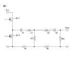
図2は、水中カメラ10の受電回路16と、電源装置20の送電回路23の回路構成の一例を示す図である。図2に示されるように、送電回路23は、電力供給回路41と、コンデンサ44及び送信コイル45を有する共振回路43と、電圧検出回路46と、ゲートドライバ47と、制御回路48とを有する。一方、受電回路16は、受信コイル51及びコンデンサ52を有する共振回路50と、整流平滑回路53とを有する。 FIG. 2 is a diagram illustrating an example of a circuit configuration of the
先ず、送電回路23について説明する。
電力供給回路41は、調節可能な動作周波数を持つ交流電力を共振回路43へ供給する。そのために、電力供給回路41は、二つのスイッチング素子42−1、42−2とを有する。First, the
The
二つのスイッチング素子42−1、42−2は、スイッチ24を介して、バッテリ22の正極側端子と負極側端子との間に直列に接続される。また本実施形態では、バッテリ22の正極側に、スイッチ24を介して、スイッチング素子42−1が接続され、一方、バッテリ22の負極側に、スイッチング素子42−1が接続される。なお、スイッチ24は、スイッチング素子42−2とバッテリ22の負極側端子間に接続されてもよい。各スイッチング素子42−1、42−2は、例えば、nチャネル型のMOSFETとすることができる。そしてスイッチング素子42−1のドレイン端子は、バッテリ22の正極側端子と接続され、スイッチング素子42−1のソース端子は、スイッチング素子42−2のドレイン端子と接続される。また、スイッチング素子42−2のソース端子は、バッテリ22の負極側端子と接続される。さらに、スイッチング素子42−1のソース端子、及び、スイッチング素子42−2のドレイン端子は、コンデンサ44を介して送信コイル45の一端に接続され、スイッチング素子42−2のソース端子は、送信コイル45の他端に直接接続される。 The two switching elements 42-1 and 42-2 are connected in series between the positive terminal and the negative terminal of the
また、各スイッチング素子42−1、42−2のゲート端子は、ゲートドライバ47を介して制御回路48と接続される。さらに、各スイッチング素子42−1、42−2のゲート端子は、オンとなる電圧が印加されたときにそのスイッチング素子がオンとなることを保証するために、それぞれ、抵抗R1、R2を介してソース端子と接続される。そして各スイッチング素子42−1、42−2は、制御回路48からの制御信号によって、交互にオン/オフが切り替えられる。これにより、バッテリ22から供給された直流電力は、コンデンサ44による充放電を介して交流電力に変換され、コンデンサ44及び送信コイル45からなる共振回路43に供給される。 The gate terminals of the switching elements 42-1 and 42-2 are connected to the
共振回路43は、コンデンサ44と送信コイル45とにより形成されるLC共振回路である。
コンデンサ44は、その一端がスイッチング素子42−1のソース端子、及び、スイッチング素子42−2のドレイン端子と接続され、他端が送信コイル45の一端と接続される。The
One end of the
送信コイル45の一端は、コンデンサ44の他端と接続され、送信コイル45の他端は、バッテリ22の負極側端子及びスイッチング素子42−2のソース端子と接続される。そして送信コイル45は、電力供給回路41から供給された交流電力により、送信コイル45自身を流れる電流に応じた磁場を生じさせる。そして送信コイル45と受信コイル51間の距離が共振可能なほど近い場合に、送信コイル45は、受信コイル51と共振して、空間を介して受信コイル51へ電力を伝送する。 One end of the
電圧検出回路46は、送信コイル45の両端子間に印加される交流電圧を所定の周期ごとに検出する。なお、所定の周期は、例えば、送信コイル45に供給される交流電力の動作周波数の想定される最小値に相当する周期よりも長く、例えば、50msec〜1secに設定される。また、電圧検出回路46は、検出する交流電圧として、例えば、その交流電圧のピーク値、あるいは、実効値を計測する。そして電圧検出回路46は、その交流電圧を表す電圧検出信号を制御回路48へ出力する。そのために、電圧検出回路46は、例えば、交流電圧を検出できる公知の様々な電圧検出回路の何れかとすることができる。 The
ゲートドライバ47は、制御回路48から、各スイッチング素子42−1、42−2のオン/オフを切り替える制御信号を受信し、その制御信号に応じて、各スイッチング素子42−1、42−2のゲート端子に印加する電圧を変化させる。すなわち、ゲートドライバ47は、スイッチング素子42−1をオンにする制御信号を受け取ると、スイッチング素子42−1のゲート端子に、スイッチング素子42−1がオンとなり、バッテリ22からの電流がスイッチング素子42−1を流れるようになる、相対的に高い電圧を印加する。一方、ゲートドライバ47は、スイッチング素子42−1をオフにする制御信号を受け取ると、スイッチング素子42−1のゲート端子に、スイッチング素子42−1がオフとなり、バッテリ22からの電流がスイッチング素子42−1を流れなくなる、相対的に低い電圧を印加する。ゲートドライバ47は、スイッチング素子42−2についても同様に、ゲート端子に印加する電圧を制御する。 The
制御回路48は、例えば、不揮発性のメモリ回路及び揮発性のメモリ回路と、演算回路と、他の回路と接続するためのインターフェース回路とを有し、電圧検出信号で示される送信コイル45に印加される交流電圧に応じて、電力供給回路41の動作周波数、すなわち、電力供給回路41が共振回路43に供給する交流電力の動作周波数を調節する。 The
そのために、本実施形態では、制御回路48は、スイッチング素子42−1とスイッチング素子42−2とが交互にオンとなり、かつ、動作周波数に対応する1周期内でスイッチング素子42−1がオンとなっている期間とスイッチング素子42−2がオンとなっている期間とが等しくなるように、各スイッチング素子42−1、42−2を制御する。なお、制御回路48は、スイッチング素子42−1とスイッチング素子42−2とが同時にオンとなり、バッテリ22が短絡されることを防止するために、スイッチング素子42−1とスイッチング素子42−2のオン/オフを切り替える際に、両方のスイッチング素子がオフとなるデッドタイムを設けてもよい。 For this reason, in the present embodiment, the
本実施形態では、制御回路48は、送信コイル45に印加される交流電圧が高くなる方向に、動作周波数、すなわち、各スイッチング素子42−1、42−2のオン/オフの切替周期を変化させる。さらに、制御回路48は、上述した、水中カメラ10からの無線信号を受信したか否かの判定を一定周期で行う。そして制御回路48は、水中カメラ10からの無線信号を所定回連続して受信できなかった場合、スイッチング素子42−1、42−2をオフにする。
なお、制御回路48による各スイッチング素子42−1、42−2の制御の詳細については後述する。In the present embodiment, the
Details of the control of the switching elements 42-1 and 42-2 by the
次に、受電回路16について説明する。
共振回路50は、受信コイル51とコンデンサ52とからなるLC共振回路である。そして共振回路50が有する受信コイル51は、その一端でコンデンサ52に接続されるとともに、他端で整流平滑回路53に接続される。Next, the
The
受信コイル51は、送電回路23の送信コイル45に流れる交流電流により生じる磁場と共鳴することで、送信コイル45と共振して、送信コイル45から電力を受信する。そして受信コイル51は、コンデンサ52を介して受信した電力を整流平滑回路53へ出力する。なお、受信コイル51の巻き数と、送電回路23の送信コイル45の巻き数は同一でもよく、あるいは、異なっていてもよい。また、共振回路50の共振周波数が送電回路23の共振回路43の共振周波数と等しくなるように、受信コイル51のインダクタンス及びコンデンサ52の静電容量は設定されることが好ましい。 The
コンデンサ52は、その一端で受信コイル51と接続され、他端で整流平滑回路53と接続される。そしてコンデンサ52は、受信コイル51にて受信した電力を、整流平滑回路53へ出力する。 The capacitor 52 is connected to the receiving
整流平滑回路53は、受信コイル51及びコンデンサ52により受信された電力を整流し、かつ、平滑化して、直流電力に変換する。そして整流平滑回路53は、その直流電力を、水中カメラ10の各部へ出力する。そのために、整流平滑回路53は、例えば、全波整流回路と平滑コンデンサとを有する。さらに、水中カメラ10が、動作電圧の異なる回路を含んでいる場合、整流平滑回路53は、各回路に適した直流電圧を持つ電力を供給できるようにDC-DCコンバータを含んでいてもよい。 The rectifying / smoothing
以下、送電回路23と受電回路16間の非接触給電動作の詳細について説明する。 Hereinafter, details of the non-contact power feeding operation between the
図3は、送電回路23と受電回路16の等価回路図である。ここで、L1、L3は、それぞれ、送電側、受電側の漏れインダクタンスであり、L2は、相互インダクタンスである。送信コイル45及び受信コイル51の自己インダクタンスをL0、送信コイル45と受信コイル51間の結合度をkとすると、L1=L3=(1-k)L0、L2=kL0となる。例えば、L0=30.5μH、k=0.731028とすると、L1=L3=8.205μH、L2=22.3μHとなる。結合度kは、一般に、送信コイル45と受信コイル51間の距離が狭いほど、大きな値となる。この場合、Fパラメータ解析により表される、伝送行列A(f)は、次式で表される。
図4は、図3に示した等価回路のインピーダンスの周波数特性の一例を示す図である。図4において、横軸は周波数を表し、縦軸は、インピーダンスを表す。なお、等価回路のインピーダンスは、2行2列で表される、(1)式の伝送行列A(f)における、左下の要素に対する左上の要素の比の絶対値として算出される。そしてグラフ400は、インピーダンスの周波数特性を表す。なお、グラフ400は、L0=30.5μH、k=0.731028とし、C1=C2=180nF、R1=R2=270mΩとして、(1)式に基づいて算出した。FIG. 4 is a diagram showing an example of frequency characteristics of impedance of the equivalent circuit shown in FIG. In FIG. 4, the horizontal axis represents frequency, and the vertical axis represents impedance. Note that the impedance of the equivalent circuit is calculated as the absolute value of the ratio of the upper left element to the lower left element in the transmission matrix A (f) of the equation (1) represented by 2 rows and 2 columns. The
図4に示されるように、結合度kが上記のように比較的大きな値となる場合、インピーダンスの周波数特性は、二つの極小値を持つ。すなわち、送信コイル45と受信コイル51とが共振する周波数が二つ存在し、各共振周波数においてインピーダンスが極小、すなわち、エネルギー伝送電力量が極大となる。したがって、送電回路23の共振回路43に供給される交流電力の動作周波数が、何れかの共振周波数に近いほど、送電側と受電側との間のインピーダンスが低下し、送信コイル45から受信コイル51へ伝送されるエネルギー伝送電力量を大きくできることになる。そのため、共振回路43に供給される交流電力の動作周波数が、何れかの共振周波数に近いほど、受電側の受信コイル51の両端子間の交流電圧も高くなる。 As shown in FIG. 4, when the degree of coupling k is a relatively large value as described above, the frequency characteristic of the impedance has two minimum values. That is, there are two frequencies at which the
また、受電側の交流電圧と送電側の交流電圧との関係は、以下の関係式で表される。
そこで、送電回路23の制御回路48は、電圧検出信号で示される、送信コイル45に印加される交流電圧が高くなる方向に、共振回路43に供給する交流電力の動作周波数、すなわち、各スイッチング素子42−1、42−2のオン/オフの切替周期を一定周期ごとに変化させる。 Therefore, the
例えば、制御回路48は、ある時点での動作周波数と送信コイル45に印加される交流電圧の値を、制御回路48が有するメモリ回路に保存しておく。そして制御回路48は、動作周波数を、所定量(例えば、10Hz〜100Hz)だけ高くなる方向、あるいは低くなる方向へ変化させる。そして制御回路48は、動作周波数の変更後において電圧検出回路46から取得した電圧検出信号で示される、最新の交流電圧の値と、記憶している直前の交流電圧の値とを比較する。最新の交流電圧の値の方が、直前の交流電圧の値よりも高い場合、制御回路48は、動作周波数を前回の変更方向と同じ方向に所定量変化させる。例えば、前回の動作周波数変更時において動作周波数を高くしており、かつ、最新の交流電圧の値の方が、直前の交流電圧の値よりも高い場合、制御回路48は、動作周波数をさらに所定量だけ高くする。逆に、最新の交流電圧の値の方が、直前の交流電圧の値よりも低い場合、制御回路48は、動作周波数を前回の変更方向とは逆方向に所定量変化させる。例えば、前回の動作周波数変更時において動作周波数を高くしており、かつ、最新の交流電圧の値が、直前の交流電圧の値よりも低い場合、制御回路48は、動作周波数を所定量だけ低くする。なお、制御回路48は、最新の交流電圧の値と直前の交流電圧の値とが等しい場合、動作周波数を何れの方向に変化させてもよい。これにより、制御回路48は、動作周波数を、送信コイル45と受信コイル51間の何れかの共振周波数に近づけることができる。
なお、制御回路18は、最新の交流電圧の値が所定の閾値以上となった場合、動作周波数の調整を停止し、その停止以降、動作周波数を一定に保ってもよい。そして制御回路18は、動作周波数の調整を停止した後に、最新の交流電圧の値が所定の閾値未満となった場合に、動作周波数の調整を再開してもよい。For example, the
The
また、制御回路48は、給電を開始してから最初の動作周波数の変更の際、動作周波数を高い方へ変更させてもよく、あるいは、動作周波数を低い方へ変更させてもよい。 In addition, the
また、送信コイル45と受信コイル51間の距離がある程度離れている場合、送信コイル45と受信コイル51間の磁気共鳴による共振周波数は一つとなり、その共振周波数は、共振回路43自身の共振周波数と等しくなる。そしてその一つの共振周波数は、送信コイル45と受信コイル51間の距離が近い場合に表れる二つの共振周波数の間に含まれる。そこで、制御回路48のメモリ回路に、予め、共振回路43自身の共振周波数を記憶しておき、制御回路48は、給電開始時の動作周波数を、共振回路43自身の共振周波数に設定してもよい。あるいは、制御回路48は、前回の給電終了時における動作周波数をメモリ回路に記憶しておき、その記憶した動作周波数を、次回の給電開始時における動作周波数としてもよい。このように給電開始時の動作周波数を設定することで、制御回路48は、動作周波数が送信コイル45と受信コイル51間の磁気共鳴による何れかの共振周波数に近づくまでに要する時間を短縮できる。 Further, when the distance between the
なお、動作周波数の下限値及び上限値は予め設定されていてもよい。そして制御回路48は、その動作周波数の下限値と上限値の間で動作周波数を調節してもよい。この場合、例えば、動作周波数の下限値及び上限値は、それぞれ、送信コイル45と受信コイル51間の磁気共鳴による共振周波数の想定される下限値及び上限値に設定される。 Note that the lower limit value and the upper limit value of the operating frequency may be set in advance. The
また、制御回路48は、電圧検出回路46から取得した電圧検出信号で示される、最新の交流電圧の値が所定の閾値以上である場合には、動作周波数を変更しなくてもよい。さらに、制御回路48は、最新の交流電圧の値と直前の交流電圧の値との差の絶対値が小さいほど、動作周波数の変更量も小さくしてもよい。 The
以上に説明してきたように、この非接触給電システムでは、電源装置が、非接触給電方式により電力供給可能な送電回路と非接触給電方式により受電可能な受電回路とバッテリとを有しているので、電源装置及び電源装置から伝送された電力により動作する電子装置の両方について外部に露出した電気接点を設けなくてよい。そのため、この非接触給電システムでは、電源装置及び電子装置の両方について、防水性を向上することができる。またこの非接触給電システムでは、電源装置が経年劣化あるいは故障した場合にも、電源装置だけを取り換えることが可能である。そのため、電源装置の寿命よりも電子装置を長期間使用することができる。さらに、この非接触給電システムでは、起動機構とスイッチとにより、電源装置が電子装置に取り付けられている場合に電力伝送が行われるので、電源装置のバッテリ持続時間を長くすることができる。さらに、この非接触給電システムは、電子装置と電源装置間の通信により、電力伝送を継続するか否かを判定するので、電源装置が誤って他の機器などに取り付けられても電源装置が動作し続けることを防止できる。 As described above, in this non-contact power feeding system, the power supply device has a power transmission circuit that can supply power by the non-contact power feeding method, a power receiving circuit that can receive power by the non-contact power feeding method, and a battery. In addition, it is not necessary to provide externally exposed electrical contacts for both the power supply device and the electronic device that operates with the power transmitted from the power supply device. Therefore, in this non-contact power feeding system, waterproofness can be improved for both the power supply device and the electronic device. Further, in this non-contact power supply system, even when the power supply device is aged or broken down, it is possible to replace only the power supply device. Therefore, the electronic device can be used for a longer period than the life of the power supply device. Furthermore, in this non-contact power feeding system, since the power transmission is performed when the power supply device is attached to the electronic device by the activation mechanism and the switch, the battery duration time of the power supply device can be increased. Furthermore, this non-contact power supply system determines whether or not to continue power transmission through communication between the electronic device and the power supply device, so that the power supply device operates even if it is accidentally attached to other devices. Can be prevented from continuing.
なお、変形例によれば、水中カメラ10の送信回路17及び電源装置20の受信回路25は省略されてもよい。この場合には、電源装置20は、水中カメラ10から取り外され、スイッチがオフとなることによってのみ、電力伝送を停止する。 According to the modification, the
また、電源装置20が水中カメラ10に取り付けられた状態では、水中カメラ10の受電回路16と、電源装置20の送電回路23の位置関係は一定に保たれる。そこで他の変形例によれば、電源装置20の送電回路23において、電圧検出回路46は省略されてもよい。そして送電回路23の制御回路48は、電源装置20が水中カメラ10に取り付けられた状態において想定される送信コイル45と受信コイル51間の距離に応じた共振周波数で各スイッチング素子42−1、42−2を交互にオン・オフ制御してもよい。 Further, in a state where the
このように、当業者は、本発明の範囲内で、実施される形態に合わせて様々な変更を行うことができる。 As described above, those skilled in the art can make various modifications in accordance with the embodiment to be implemented within the scope of the present invention.
1 非接触給電システム
10 水中カメラ(電子装置)
11 筐体
12 撮像部
13 ユーザインターフェース
14 メモリ
15 制御回路
16 受電回路
17 送信回路
18 磁石
20 電源装置
21 受電回路
22 バッテリ
23 送電回路
24 スイッチ
25 受信回路
30 充電装置
31 送電回路
42−1、42−2 スイッチング素子
43 共振回路
44 コンデンサ
45 送信コイル
46 電圧検出回路
47 ゲートドライバ
48 制御回路
50 共振回路
51 受信コイル
52 コンデンサ
53 整流平滑回路1 Non-contact
DESCRIPTION OF
Claims (5)
Translated fromJapanese前記電源装置は、
バッテリと、
非接触で伝送された電力を受信し、当該電力により前記バッテリを充電する受電回路と、
前記バッテリに蓄電された電力を利用して、非接触で前記電子装置へ電力を伝送する送電回路と、
を有する非接触給電システム。A non-contact power feeding system having a power supply device and an electronic device that operates with electric power transmitted in a non-contact manner from the power supply device,
The power supply device
Battery,
A power receiving circuit that receives power transmitted in a contactless manner and charges the battery with the power;
A power transmission circuit that transmits power to the electronic device in a non-contact manner using power stored in the battery;
A contactless power supply system.
前記電子装置は、前記電子装置の所定の位置に前記電源装置が取り付けられたときに、前記スイッチと対向する位置に設けられ、かつ、前記スイッチをオンにする起動機構をさらに有する、請求項1に記載の非接触給電システム。The power supply device further includes a switch connected between the battery and the power transmission circuit, and the power transmission circuit starts transmitting power when the switch is turned on,
The electronic device further includes an activation mechanism provided at a position facing the switch when the power supply device is attached to a predetermined position of the electronic device and turning on the switch. Contactless power supply system described in 1.
前記電源装置は、前記無線信号を受信する受信回路をさらに有し、
前記電源装置の前記送電回路は、前記電子装置への電力供給を開始した後に、一定期間にわたって前記送信回路からの前記無線信号を受信できない場合に、前記電子装置への電力伝送を停止する、請求項2に記載の非接触給電システム。The electronic device further includes a transmission circuit that transmits a radio signal at a predetermined cycle while power is transmitted from the power supply device,
The power supply apparatus further includes a receiving circuit that receives the wireless signal,
The power transmission circuit of the power supply device stops power transmission to the electronic device when the wireless signal from the transmission circuit cannot be received for a certain period of time after starting power supply to the electronic device. Item 3. The non-contact power feeding system according to Item 2.
前記電源装置の前記送電回路は、予め記憶した識別情報と、前記受信回路が受信した無線信号に含まれる前記識別情報とが一致しない場合、前記送信回路からの前記無線信号を受信していないと判定する、請求項3に記載の非接触給電システム。The wireless signal includes identification information of the electronic device,
When the power transmission circuit of the power supply device does not receive the wireless signal from the transmission circuit when the identification information stored in advance and the identification information included in the wireless signal received by the reception circuit do not match The non-contact electric power feeding system according to claim 3 which judges.
Priority Applications (5)
| Application Number | Priority Date | Filing Date | Title |
|---|---|---|---|
| JP2015233463AJP2017103858A (en) | 2015-11-30 | 2015-11-30 | Contactless power supply system |
| PCT/JP2016/081014WO2017094386A1 (en) | 2015-11-30 | 2016-10-19 | Non-contact power supply system |
| CN201680045955.6ACN107925269A (en) | 2015-11-30 | 2016-10-19 | Non-contact power supply system |
| DE112016005456.4TDE112016005456T5 (en) | 2015-11-30 | 2016-10-19 | Contactless power supply system |
| US15/893,839US10637297B2 (en) | 2015-11-30 | 2018-02-12 | Non-contact power feeding system |
Applications Claiming Priority (1)
| Application Number | Priority Date | Filing Date | Title |
|---|---|---|---|
| JP2015233463AJP2017103858A (en) | 2015-11-30 | 2015-11-30 | Contactless power supply system |
Publications (1)
| Publication Number | Publication Date |
|---|---|
| JP2017103858Atrue JP2017103858A (en) | 2017-06-08 |
Family
ID=58797033
Family Applications (1)
| Application Number | Title | Priority Date | Filing Date |
|---|---|---|---|
| JP2015233463APendingJP2017103858A (en) | 2015-11-30 | 2015-11-30 | Contactless power supply system |
Country Status (5)
| Country | Link |
|---|---|
| US (1) | US10637297B2 (en) |
| JP (1) | JP2017103858A (en) |
| CN (1) | CN107925269A (en) |
| DE (1) | DE112016005456T5 (en) |
| WO (1) | WO2017094386A1 (en) |
Cited By (1)
| Publication number | Priority date | Publication date | Assignee | Title |
|---|---|---|---|---|
| CN109088481A (en)* | 2018-10-16 | 2018-12-25 | 大连理工大学 | Wireless electric energy transmission device under cylindrical quadripolar plate constitution water based on field coupling |
Families Citing this family (2)
| Publication number | Priority date | Publication date | Assignee | Title |
|---|---|---|---|---|
| JP7105428B2 (en) | 2019-03-28 | 2022-07-25 | 株式会社エーオーアイ・ジャパン | A wireless power supply system having a battery-equipped device fitted with a power receiving device equipped with a light unit |
| CN110954837A (en)* | 2019-12-17 | 2020-04-03 | 常州格力博有限公司 | Battery pack diagnostic instrument |
Citations (8)
| Publication number | Priority date | Publication date | Assignee | Title |
|---|---|---|---|---|
| JPH10215530A (en)* | 1997-01-28 | 1998-08-11 | Matsushita Electric Works Ltd | Non-contact power transmission device |
| JP2001112191A (en)* | 1999-10-05 | 2001-04-20 | Sharp Corp | Non-contact power and signal transmission system |
| JP2010259172A (en)* | 2009-04-22 | 2010-11-11 | Panasonic Electric Works Co Ltd | Contactless power supply system |
| JP2011205830A (en)* | 2010-03-26 | 2011-10-13 | Panasonic Electric Works Co Ltd | Power supply system |
| WO2012036024A1 (en)* | 2010-09-17 | 2012-03-22 | ソニー株式会社 | Power supply method, charging control device and power supply system |
| JP2013078240A (en)* | 2011-09-30 | 2013-04-25 | Panasonic Corp | Contactless power transmission device, and power transmission device and power reception device thereof |
| JP2014039437A (en)* | 2012-08-20 | 2014-02-27 | Lequio Power Technology Corp | Charge and discharge device |
| JP2015171160A (en)* | 2014-03-04 | 2015-09-28 | パナソニックIpマネジメント株式会社 | non-contact charging system |
Family Cites Families (13)
| Publication number | Priority date | Publication date | Assignee | Title |
|---|---|---|---|---|
| CN101860089B (en) | 2005-07-12 | 2013-02-06 | 麻省理工学院 | wireless non-radiative energy transfer |
| CA2701394A1 (en)* | 2007-10-17 | 2009-04-23 | Access Business Group International Llc | Laptop and portable electronic device wireless power supply systems |
| US9013141B2 (en)* | 2009-04-28 | 2015-04-21 | Qualcomm Incorporated | Parasitic devices for wireless power transfer |
| US8427101B2 (en)* | 2009-11-18 | 2013-04-23 | Nokia Corporation | Wireless energy repeater |
| JP2011160505A (en)* | 2010-01-29 | 2011-08-18 | Sony Corp | Wireless charging apparatus and wireless charging system |
| CN202998741U (en)* | 2012-10-10 | 2013-06-12 | 罗天成 | Novel waterproof electronic product |
| JP2014203940A (en) | 2013-04-04 | 2014-10-27 | 日本電信電話株式会社 | Field-effect transistor |
| US9281720B2 (en)* | 2013-05-31 | 2016-03-08 | ConvenientPower HK Ltd. | Inductive power transfer using a relay coil |
| US9281119B2 (en)* | 2013-11-13 | 2016-03-08 | The Hong Kong Polytechnic University | Three-coil topology for wireless power transfer |
| US20160141908A1 (en)* | 2014-11-14 | 2016-05-19 | Motorola Solutions, Inc | Method and apparatus for efficiency compliance in wireless charging systems |
| US9614385B2 (en)* | 2014-11-14 | 2017-04-04 | Motorola Solutions, Inc. | Apparatus and method for full-orientation over-the-air charging in portable electronic devices |
| US20170060245A1 (en) | 2015-08-31 | 2017-03-02 | Fujitsu Ten Limited | Input device, integrated input system, input device control method, and program |
| JP6960716B2 (en)* | 2015-08-31 | 2021-11-05 | 株式会社デンソーテン | Input device, display device, input device control method and program |
- 2015
- 2015-11-30JPJP2015233463Apatent/JP2017103858A/enactivePending
- 2016
- 2016-10-19WOPCT/JP2016/081014patent/WO2017094386A1/ennot_activeCeased
- 2016-10-19CNCN201680045955.6Apatent/CN107925269A/enactivePending
- 2016-10-19DEDE112016005456.4Tpatent/DE112016005456T5/ennot_activeWithdrawn
- 2018
- 2018-02-12USUS15/893,839patent/US10637297B2/enactiveActive
Patent Citations (8)
| Publication number | Priority date | Publication date | Assignee | Title |
|---|---|---|---|---|
| JPH10215530A (en)* | 1997-01-28 | 1998-08-11 | Matsushita Electric Works Ltd | Non-contact power transmission device |
| JP2001112191A (en)* | 1999-10-05 | 2001-04-20 | Sharp Corp | Non-contact power and signal transmission system |
| JP2010259172A (en)* | 2009-04-22 | 2010-11-11 | Panasonic Electric Works Co Ltd | Contactless power supply system |
| JP2011205830A (en)* | 2010-03-26 | 2011-10-13 | Panasonic Electric Works Co Ltd | Power supply system |
| WO2012036024A1 (en)* | 2010-09-17 | 2012-03-22 | ソニー株式会社 | Power supply method, charging control device and power supply system |
| JP2013078240A (en)* | 2011-09-30 | 2013-04-25 | Panasonic Corp | Contactless power transmission device, and power transmission device and power reception device thereof |
| JP2014039437A (en)* | 2012-08-20 | 2014-02-27 | Lequio Power Technology Corp | Charge and discharge device |
| JP2015171160A (en)* | 2014-03-04 | 2015-09-28 | パナソニックIpマネジメント株式会社 | non-contact charging system |
Cited By (2)
| Publication number | Priority date | Publication date | Assignee | Title |
|---|---|---|---|---|
| CN109088481A (en)* | 2018-10-16 | 2018-12-25 | 大连理工大学 | Wireless electric energy transmission device under cylindrical quadripolar plate constitution water based on field coupling |
| CN109088481B (en)* | 2018-10-16 | 2024-01-02 | 大连理工大学 | Cylindrical quadrupole plate structure underwater wireless power transmission device based on electric field coupling |
Also Published As
| Publication number | Publication date |
|---|---|
| CN107925269A (en) | 2018-04-17 |
| US20180183270A1 (en) | 2018-06-28 |
| US10637297B2 (en) | 2020-04-28 |
| WO2017094386A1 (en) | 2017-06-08 |
| DE112016005456T5 (en) | 2018-08-16 |
Similar Documents
| Publication | Publication Date | Title |
|---|---|---|
| KR101524584B1 (en) | Power supply apparatus, method, and storage medium | |
| US9142999B2 (en) | Systems, methods, and apparatus for small device wireless charging modes | |
| JP5893285B2 (en) | Power supply apparatus and program | |
| US9595838B2 (en) | Electronic apparatus, control method and recording medium | |
| US9191075B2 (en) | Wireless power control method, system, and apparatus utilizing a wakeup signal to prevent standby power consumption | |
| KR102078073B1 (en) | Power supply apparatus | |
| US9825466B2 (en) | Power supply device, electronic device, control method, and recording medium | |
| CN102801219A (en) | Electronic device and control method thereof | |
| JP2011030294A (en) | Secondary battery device | |
| US9749018B2 (en) | Power transmission apparatus and method for controlling power transmission | |
| JP2012222946A (en) | Power supply device | |
| US9923605B2 (en) | Electronic apparatus | |
| JP5814858B2 (en) | Power transmission equipment | |
| JP2014007863A (en) | Power supply device, control method, and program | |
| JP2018148630A (en) | Control device, power receiving device, and electronic device | |
| US10637297B2 (en) | Non-contact power feeding system | |
| US20170064635A1 (en) | Power transmission apparatus and method for controlling power transmission | |
| US20130147282A1 (en) | Electronic apparatus, method, and storage medium | |
| US10404326B2 (en) | Power transmission apparatus | |
| JP2018133855A (en) | Power supply device | |
| US10389176B2 (en) | Electronic device | |
| JP2014217116A (en) | Electronic apparatus, electronic apparatus power transmission system and power reception control method | |
| CN110098645A (en) | The open loop tuning methods of electric toothbrush wireless charging system efficiency optimization | |
| KR20160034815A (en) | Electronic apparatus and power supply apparatus |
Legal Events
| Date | Code | Title | Description |
|---|---|---|---|
| A621 | Written request for application examination | Free format text:JAPANESE INTERMEDIATE CODE: A621 Effective date:20180907 | |
| A131 | Notification of reasons for refusal | Free format text:JAPANESE INTERMEDIATE CODE: A131 Effective date:20190820 | |
| A521 | Request for written amendment filed | Free format text:JAPANESE INTERMEDIATE CODE: A523 Effective date:20191017 | |
| A131 | Notification of reasons for refusal | Free format text:JAPANESE INTERMEDIATE CODE: A131 Effective date:20191119 | |
| A02 | Decision of refusal | Free format text:JAPANESE INTERMEDIATE CODE: A02 Effective date:20200526 |