JP2017100259A - Electric tool with vibration mechanism - Google Patents
Electric tool with vibration mechanismDownload PDFInfo
- Publication number
- JP2017100259A JP2017100259AJP2015236790AJP2015236790AJP2017100259AJP 2017100259 AJP2017100259 AJP 2017100259AJP 2015236790 AJP2015236790 AJP 2015236790AJP 2015236790 AJP2015236790 AJP 2015236790AJP 2017100259 AJP2017100259 AJP 2017100259A
- Authority
- JP
- Japan
- Prior art keywords
- vibration
- vibration mechanism
- cylindrical portion
- electric tool
- slit
- Prior art date
- Legal status (The legal status is an assumption and is not a legal conclusion. Google has not performed a legal analysis and makes no representation as to the accuracy of the status listed.)
- Granted
Links
- 210000000078clawAnatomy0.000claimsdescription12
- 230000000903blocking effectEffects0.000claims1
- 230000002265preventionEffects0.000abstractdescription4
- 230000000694effectsEffects0.000description5
- 230000002093peripheral effectEffects0.000description5
- 230000001105regulatory effectEffects0.000description3
- 230000004323axial lengthEffects0.000description2
- 238000001514detection methodMethods0.000description2
- 230000000717retained effectEffects0.000description2
- 125000006850spacer groupChemical group0.000description2
- 229910000831SteelInorganic materials0.000description1
- 239000000969carrierSubstances0.000description1
- 238000005336crackingMethods0.000description1
- 238000009413insulationMethods0.000description1
- 230000000149penetrating effectEffects0.000description1
- 230000003014reinforcing effectEffects0.000description1
- 239000010959steelSubstances0.000description1
Images


Classifications
- B—PERFORMING OPERATIONS; TRANSPORTING
- B25—HAND TOOLS; PORTABLE POWER-DRIVEN TOOLS; MANIPULATORS
- B25F—COMBINATION OR MULTI-PURPOSE TOOLS NOT OTHERWISE PROVIDED FOR; DETAILS OR COMPONENTS OF PORTABLE POWER-DRIVEN TOOLS NOT PARTICULARLY RELATED TO THE OPERATIONS PERFORMED AND NOT OTHERWISE PROVIDED FOR
- B25F3/00—Associations of tools for different working operations with one portable power-drive means; Adapters therefor
- B—PERFORMING OPERATIONS; TRANSPORTING
- B25—HAND TOOLS; PORTABLE POWER-DRIVEN TOOLS; MANIPULATORS
- B25B—TOOLS OR BENCH DEVICES NOT OTHERWISE PROVIDED FOR, FOR FASTENING, CONNECTING, DISENGAGING OR HOLDING
- B25B21/00—Portable power-driven screw or nut setting or loosening tools; Attachments for drilling apparatus serving the same purpose
- B25B21/02—Portable power-driven screw or nut setting or loosening tools; Attachments for drilling apparatus serving the same purpose with means for imparting impact to screwdriver blade or nut socket
- B25B21/023—Portable power-driven screw or nut setting or loosening tools; Attachments for drilling apparatus serving the same purpose with means for imparting impact to screwdriver blade or nut socket for imparting an axial impact, e.g. for self-tapping screws
- B—PERFORMING OPERATIONS; TRANSPORTING
- B23—MACHINE TOOLS; METAL-WORKING NOT OTHERWISE PROVIDED FOR
- B23B—TURNING; BORING
- B23B45/00—Hand-held or like portable drilling machines, e.g. drill guns; Equipment therefor
- B—PERFORMING OPERATIONS; TRANSPORTING
- B25—HAND TOOLS; PORTABLE POWER-DRIVEN TOOLS; MANIPULATORS
- B25D—PERCUSSIVE TOOLS
- B25D16/00—Portable percussive machines with superimposed rotation, the rotational movement of the output shaft of a motor being modified to generate axial impacts on the tool bit
- B25D16/006—Mode changers; Mechanisms connected thereto
- B—PERFORMING OPERATIONS; TRANSPORTING
- B25—HAND TOOLS; PORTABLE POWER-DRIVEN TOOLS; MANIPULATORS
- B25F—COMBINATION OR MULTI-PURPOSE TOOLS NOT OTHERWISE PROVIDED FOR; DETAILS OR COMPONENTS OF PORTABLE POWER-DRIVEN TOOLS NOT PARTICULARLY RELATED TO THE OPERATIONS PERFORMED AND NOT OTHERWISE PROVIDED FOR
- B25F5/00—Details or components of portable power-driven tools not particularly related to the operations performed and not otherwise provided for
- B25F5/001—Gearings, speed selectors, clutches or the like specially adapted for rotary tools
- B—PERFORMING OPERATIONS; TRANSPORTING
- B25—HAND TOOLS; PORTABLE POWER-DRIVEN TOOLS; MANIPULATORS
- B25D—PERCUSSIVE TOOLS
- B25D2211/00—Details of portable percussive tools with electromotor or other motor drive
- B25D2211/06—Means for driving the impulse member
- B25D2211/062—Cam-actuated impulse-driving mechanisms
- B25D2211/064—Axial cams, e.g. two camming surfaces coaxial with drill spindle
- B—PERFORMING OPERATIONS; TRANSPORTING
- B25—HAND TOOLS; PORTABLE POWER-DRIVEN TOOLS; MANIPULATORS
- B25D—PERCUSSIVE TOOLS
- B25D2216/00—Details of portable percussive machines with superimposed rotation, the rotational movement of the output shaft of a motor being modified to generate axial impacts on the tool bit
- B25D2216/0007—Details of percussion or rotation modes
- B25D2216/0023—Tools having a percussion-and-rotation mode
- B—PERFORMING OPERATIONS; TRANSPORTING
- B25—HAND TOOLS; PORTABLE POWER-DRIVEN TOOLS; MANIPULATORS
- B25D—PERCUSSIVE TOOLS
- B25D2216/00—Details of portable percussive machines with superimposed rotation, the rotational movement of the output shaft of a motor being modified to generate axial impacts on the tool bit
- B25D2216/0007—Details of percussion or rotation modes
- B25D2216/0038—Tools having a rotation-only mode
Landscapes
- Engineering & Computer Science (AREA)
- Mechanical Engineering (AREA)
- Drilling And Boring (AREA)
- Portable Power Tools In General (AREA)
Abstract
Description
Translated fromJapanese本発明は、震動ドライバドリル等、最終出力軸に軸方向の震動を付与する震動モードを選択可能な震動機構付き電動工具に関する。 The present invention relates to a power tool with a vibration mechanism capable of selecting a vibration mode that applies axial vibration to a final output shaft, such as a vibration driver drill.
震動機構付き電動工具として、例えば特許文献1には、モータからギヤアッセンブリを介して最終出力軸であるスピンドルにトルク伝達すると共に、震動機構を設けて、スピンドルに軸方向の震動を付与する震動モードを選択可能とした震動ドライバドリルが開示されている。この震動機構は、ギヤアッセンブリに設けられる前側のギヤケース内に、スピンドルに外装される2つのカムを設けて第1カムをスピンドルと一体に固着し、第2カムを、スピンドルと別体回転且つ軸方向へ移動可能に設けてギヤケースの前端に設けたスリット内に収容した震動切替レバーと係合させ、その震動切替レバーを、ギヤケースに外装したモードチェンジリングによって前後移動させることで、第2カムを第1カムと係合する位置と係合しない位置とに切り替えることで、震動モードの選択ができるようになっている。 As an electric tool with a vibration mechanism, for example, Patent Document 1 discloses a vibration mode in which torque is transmitted from a motor to a spindle as a final output shaft through a gear assembly, and a vibration mechanism is provided to impart a vibration in the axial direction to the spindle. A seismic driver drill that can be selected is disclosed. In this vibration mechanism, two cams mounted on the spindle are provided in a front gear case provided in the gear assembly so that the first cam is fixed integrally with the spindle, and the second cam is rotated and separated from the spindle. The second cam is moved forward and backward by a mode change ring externally mounted on the gear case, and is engaged with a vibration switching lever accommodated in a slit provided at the front end of the gear case. The vibration mode can be selected by switching between a position where the first cam is engaged and a position where the first cam is not engaged.
上記震動ドライバドリルにおいて、ギヤケースの前端には、モードチェンジリング等を抜け止めする平板状の止め板が前方からネジ止めされるのみであるため、震動ドライバドリルを落下等させた際、外部からの衝撃がギヤケースへダイレクトに伝わり、スリット部分からギヤケースがひび割れ等して破損が生じるおそれがある。ギヤケースの前端に破損防止用の補強部材を設けることも考えられるが、部品点数が増えてコストアップに繋がる上、軸方向の全長が長くなってコンパクト化を阻害してしまう。 In the above-mentioned vibration driver drill, a flat stop plate for retaining the mode change ring etc. is only screwed from the front at the front end of the gear case, so when dropping the vibration driver drill, etc. The impact is directly transmitted to the gear case, and there is a risk that the gear case cracks from the slit portion and breaks. Although it is conceivable to provide a reinforcing member for preventing breakage at the front end of the gear case, the number of parts increases, leading to an increase in cost, and the overall length in the axial direction becomes long, thereby obstructing compactization.
そこで、本発明は、破損防止用の別部材を用いることなく、簡単且つコンパクトな構成でギヤケースの破損を効果的に防止できる震動機構付き電動工具を提供することを目的としたものである。 Accordingly, an object of the present invention is to provide an electric tool with a vibration mechanism that can effectively prevent damage to a gear case with a simple and compact configuration without using a separate member for preventing damage.
上記目的を達成するために、請求項1に記載の発明は、ハウジングと、ハウジング内に収容されるモータと、モータの回転が伝達され、ギヤケースに収容される減速機構と、減速機構から回転が伝達され、ギヤケースの前端に設けた筒状部内に軸受を介して保持されて前方へ突出する最終出力軸と、筒状部内に設けられ、最終出力軸に軸方向の震動を付与可能な震動機構と、筒状部の前端へ軸方向に形成されたスリットに収容され、外部からの操作によってスリット内を前後移動することで震動機構の作動の有無を切り替える震動切替部材と、筒状部の前端に取り付けられてスリットを塞ぐ止め部材と、を含んでなる震動機構付き電動工具であって、
止め部材には、スリットが形成される筒状部の前端外周に当接して筒状部の前端の拡開を防止する拡開防止部が設けられていることを特徴とする。
請求項2に記載の発明は、請求項1の構成において、拡開防止部は、筒状部の前端に外側から嵌合するリング状の突条であることを特徴とする。
請求項3に記載の発明は、請求項1又は2の構成において、筒状部は、後側の大径部と、その大径部より小径でスリットが前端に形成される前側の小径部とからなり、小径部には、円盤状とした止め部材に抜け止めされる回転操作部材が外装されており、回転操作部材には、その回転操作に伴って止め部材に設けた複数の係合凹部へ弾性的に係合するクリック用の板バネが設けられて、板バネは、止め部材と回転操作部材との間に、回転操作部材の前面に沿って形成した爪部を差し込むことで抜け止め状態で取り付けられることを特徴とする。
請求項4に記載の発明は、請求項3の構成において、係合凹部は、止め部材の外周に設けられることを特徴とする。
請求項5に記載の発明は、請求項1乃至4の何れかの構成において、止め部材は、筒状部への取り付け状態で軸受の前方への移動を規制することを特徴とする。
請求項6に記載の発明は、請求項3又は4の構成において、回転操作部材は、最終出力軸のトルク調整用であることを特徴とする。In order to achieve the above object, the invention described in claim 1 is directed to a housing, a motor accommodated in the housing, a reduction mechanism that receives rotation of the motor and is accommodated in a gear case, and rotation from the reduction mechanism. A final output shaft that is transmitted and held in a cylindrical portion provided at the front end of the gear case via a bearing and protrudes forward, and a vibration mechanism that is provided in the cylindrical portion and can impart axial vibration to the final output shaft And a vibration switching member that is accommodated in a slit formed in the axial direction toward the front end of the cylindrical portion, and that switches the presence or absence of the vibration mechanism by moving back and forth in the slit by an external operation, and the front end of the cylindrical portion An electric tool with a vibration mechanism comprising:
The stop member is provided with an expansion preventing portion that abuts the outer periphery of the front end of the cylindrical portion where the slit is formed and prevents the front end of the cylindrical portion from expanding.
According to a second aspect of the present invention, in the configuration of the first aspect, the spread preventing portion is a ring-shaped protrusion that fits from the outside to the front end of the cylindrical portion.
According to a third aspect of the present invention, in the configuration of the first or second aspect, the cylindrical portion includes a rear-side large-diameter portion, and a front-side small-diameter portion having a smaller diameter than the large-diameter portion and a slit formed at the front end. The rotation operation member that is retained by the disk-shaped stop member is externally provided on the small diameter portion, and the rotation operation member includes a plurality of engagement recesses provided in the stop member in accordance with the rotation operation. A leaf spring for click that is elastically engaged is provided, and the leaf spring is retained by inserting a claw formed along the front surface of the rotation operation member between the stop member and the rotation operation member. It is attached in a state.
According to a fourth aspect of the present invention, in the configuration of the third aspect, the engaging recess is provided on the outer periphery of the stop member.
The invention according to
According to a sixth aspect of the present invention, in the configuration of the third or fourth aspect, the rotary operation member is for adjusting the torque of the final output shaft.
請求項1に記載の発明によれば、筒状部に取り付けられる止め部材に拡開防止部を設けたことで、破損防止用の別部材が不要となり、簡単且つコンパクトな構成でギヤケースの破損を効果的に防止することができる。
請求項2に記載の発明によれば、請求項1の効果に加えて、拡開防止部を、筒状部の前端に外側から嵌合するリング状の突条としたことで、筒状部に対する止め部材の取付位置を変えることなく突条による筒状部の拡開防止が可能となる。よって、拡開防止部を設けてもコンパクト化を阻害することがない。
請求項3に記載の発明によれば、請求項1又は2の効果に加えて、回転操作部材のクリック用の板バネを、止め部材と回転操作部材との間に、回転操作部材の前面と平行に形成した爪部を差し込むことで抜け止め状態で取り付けたことで、板バネを設けてもコンパクト化を阻害することがない。
請求項4に記載の発明によれば、請求項3の効果に加えて、係合凹部を止め部材の外周に設けているので、クリック音の発生機能を維持した状態で軸方向の長さを短縮することができる。
請求項5に記載の発明によれば、請求項1乃至4の何れかの効果に加えて、止め部材は、筒状部への取り付け状態で軸受の前方への移動を規制するので、止め部材を軸受の位置決め用に兼用した合理的な構成となり、軸受の組み付けが容易となって軸受の抜け止め部材も不要となる。
請求項6に記載の発明によれば、請求項3又は4の効果に加えて、回転操作部材をトルク調整用としたことで、トルク調整時にクリック音を発生させることができ、使用感が良好となる。According to the first aspect of the present invention, by providing the expansion preventing portion on the stopper member attached to the cylindrical portion, a separate member for preventing damage is unnecessary, and the gear case can be damaged with a simple and compact configuration. It can be effectively prevented.
According to the second aspect of the present invention, in addition to the effect of the first aspect, the expansion preventing portion is a ring-shaped protrusion that is fitted to the front end of the cylindrical portion from the outside, so that the cylindrical portion It is possible to prevent the tubular portion from expanding due to the ridge without changing the mounting position of the stopper member with respect to. Therefore, even if the spread prevention part is provided, the downsizing is not hindered.
According to the third aspect of the present invention, in addition to the effect of the first or second aspect, the leaf spring for clicking the rotation operation member is disposed between the front surface of the rotation operation member and the stop operation member. By attaching the claw portions formed in parallel so as to prevent them from coming off, even if a leaf spring is provided, downsizing is not hindered.
According to the fourth aspect of the invention, in addition to the effect of the third aspect, since the engaging recess is provided on the outer periphery of the stop member, the length in the axial direction is maintained in a state in which the click sound generation function is maintained. It can be shortened.
According to the fifth aspect of the present invention, in addition to the effect of any one of the first to fourth aspects, the stop member regulates the forward movement of the bearing in the state of being attached to the cylindrical portion. This is a rational configuration that also serves for positioning the bearing, facilitates assembly of the bearing, and eliminates the need for a retaining member for the bearing.
According to the sixth aspect of the invention, in addition to the effect of the third or fourth aspect, the rotation operation member is used for torque adjustment, so that a click sound can be generated at the time of torque adjustment, and the usability is good. It becomes.
以下、本発明の実施の形態を図面に基づいて説明する。
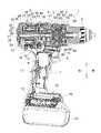
図1は、震動機構付き電動工具の一例である震動ドライバドリルの縦断面図、図2は本体部の拡大図である。この震動ドライバドリル1は、前後方向に延びる本体部2内の後方にブラシレスモータ3を収容し、ブラシレスモータ3から、前方に組み付けられるギヤアッセンブリ4を介して、ギヤアッセンブリ4から前方へ突出する最終出力軸としてのスピンドル5へトルク伝達するもので、スピンドル5の前端には、先端でビットを把持可能なドリルチャック6が設けられている。Hereinafter, embodiments of the present invention will be described with reference to the drawings.
FIG. 1 is a longitudinal sectional view of a vibration driver drill which is an example of an electric tool with a vibration mechanism, and FIG. 2 is an enlarged view of a main body. The vibration driver drill 1 accommodates a
本体部2の下方には、ハンドル7が下向きに形成されて、ハンドル7内の上側には、トリガ9を前方へ突出させたスイッチ8が設けられ、ハンドル7内の下端には、電源となるバッテリーパック11が装着されるバッテリー装着部10が形成されている。バッテリー装着部10内には、バッテリーパック11と電気的接続する端子台12が設けられると共に、その上方にコントローラ13が設けられている。14は、スイッチ8の上方に設けられたモータの正逆切替レバー、15はトリガ9の上方に設けられてドリルチャック6の前方を照射するLEDである。 A
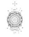
震動ドライバドリル1のハウジングは、ブラシレスモータ3を収容する筒状のモータハウジング16と、ハンドル7を形成してモータハウジング16と一体のハンドルハウジング17と、モータハウジング16の後方を閉塞するリヤカバー18とからなり、モータハウジング16とハンドルハウジング17とは、一体形成される左右一対の半割ハウジングをネジ19,19・・によって組み付けて形成される。モータハウジング16の前端には、図3に示すように、ギヤアッセンブリ4の後述する第2ギヤケース37が、前方から4本のネジ20,20・・によって固定される。 The housing of the vibration driver drill 1 includes a
ブラシレスモータ3は、筒状のステータ21とステータ21を貫通するロータ22とを有するインナロータ型で、ステータ21は、固定子鉄心23と、固定子鉄心23の前後に設けられる前絶縁部材24及び後絶縁部材25と、前絶縁部材24及び後絶縁部材25を介して固定子鉄心23に設けたティースに巻回される複数のコイル26,26・・とを有する。
ロータ22は、軸心に位置する回転軸27と、回転軸27の周囲に配置される筒状の回転子鉄心28と、回転子鉄心28に挿入された複数の永久磁石29,29・・とを有し、回転軸27の前端には、ピニオン30が取り付けられる。回転軸27の後端には、遠心ファン31が取り付けられて、当該後端はリヤカバー18に保持される軸受32によって支持されている。リヤカバー18の側面には、複数の排気口33,33・・が形成され、その前方でモータハウジング16の側面には図示しない吸気口が形成されている。34は、前絶縁部材24の前端に取り付けられるセンサ回路基板で、永久磁石29の位置を検出して回転検出信号を出力する3つの回転検出素子を搭載している。回転軸27における回転子鉄心28の前後には、バランスをとるためのバランス板35,35が固着されている。The
The
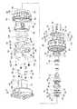
ギヤアッセンブリ4は、第1ギヤケース36と、その第1ギヤケース36の前方に組み付けられ、図4にも示すように、大径部38と筒状部としての小径部39との二段筒形状を有する第2ギヤケース37とを備える。第1ギヤケース36と大径部38との内部には、複数の遊星ギヤ41A〜41Cと、遊星ギヤ41A〜41Cを支持するキャリア42A〜42Cと、遊星ギヤ41A〜41Cの外周で噛合するインターナルギヤ43A〜43Cとを三段配置してなる減速機構40が収容されている。第1ギヤケース36の後端を閉塞するキャップ44には、回転軸27を軸支する軸受45が設けられて、ギヤアッセンブリ4の組み付け状態で、回転軸27のピニオン30は第1ギヤケース36内に突出して一段目の遊星ギヤ41Aと噛合している。 The
ここで、二段目のインターナルギヤ43Bは、二段目の遊星ギヤ41Bと噛合して第1ギヤケース36内で回転規制される前進位置と、二段目の遊星ギヤ41Bと一段目のキャリア42Aとに同時に噛合して回転フリーとなる後退位置との間で前後移動可能で、インターナルギヤ43Bの外周に係合して第1ギヤケース36の上方へ突出する連係部材46を介して、モータハウジング16の上面に設けられる操作ボタン47と連結されている。よって、操作ボタン47のスライド操作でインターナルギヤ43Bを前進位置に移動させれば、二段目の減速が機能する低速モードとなり、後退位置に移動させれば、一段目のキャリア42Aと二段目の遊星歯車41B及びキャリア42Bとが一体回転して二段目の減速がキャンセルされる高速モードとなる。 Here, the second-stage
スピンドル5は、その後端が三段目のキャリア42Cと一体のロックカム47にスプライン結合されると共に、第2ギヤケース37の小径部39内で前後の軸受48,49によって、軸方向へ前後移動可能且つ回転可能に保持されている。但し、スピンドル5は、その前方寄りに形成されたフランジ50と、前側の軸受48の前面に当接するワッシャー51との間で外装されたコイルバネ52によって、常態では軸受48の後方に設けたクリップ53が軸受48に当接する前進位置に付勢されている。 The
また、スピンドル5における軸受48,49間には、図4にも示すように、前方からリング状の第1カム55、第2カム56がそれぞれ同軸で外装されて震動機構54を形成している。第1カム55は、その後面に、複数のカム歯からなる第1カム面57を有し、軸受48の後方で小径部39内に保持されたスペーサ58内でスピンドル5と一体に固着されている。第2カム56は、前面に複数のカム歯からなる第2カム面59を、後面に周方向へ等間隔に配置される複数の爪60,60・・をそれぞれ有し、スピンドル5に遊挿されて回転可能となっている。一方、第2カム56の前後移動は、スペーサ58と、小径部39の内周に突設したストッパ部61に規制され、複数のスチールボール63,63・・を保持する一対のワッシャー62,62との間で規制されている。 Also, as shown in FIG. 4, a ring-shaped
さらに、小径部39には、前端から軸方向に沿ったスリット64,64が点対称に一対形成され、各スリット64内に、コイルバネ65と震動切替部材としての震動切替レバー66とが収容されている。各震動切替レバー66は、スリット64内で前後移動可能であるが、コイルバネ65によって前方へ付勢されている。各震動切替レバー66の後端内面側には、内側突起67が突設されて小径部39の内周側に突出し、震動切替レバー66の後述する前進位置で第2カム56の爪60に係合可能となっている。また、各震動切替レバー66の前端外面側には外側突起68が突設されて、小径部39の外周側に突出している。 Furthermore, a pair of
小径部39の前端には、止め部材としてのリテーナ69が、前方から4本のネジ70,70・・によって直交状に固定される。このリテーナ69は、中央に後述する中間リング76の嵌合孔71を有して小径部39よりも大径となる円盤状で、後面には、拡開防止部としてのリング状の突条72が突設されている。この突条72は、小径部39の前端外周に形成された切欠段部73に嵌合する内径形状を有し、小径部39の前端に突条72を外嵌した状態で、リテーナ69は切欠段部73によって後方への移動が規制されると共に、突条72の嵌合によって回転も規制される。リテーナ69の外周には、複数の係合凹部74,74・・が部分的に連続形成され、係合凹部74の非形成部分には、突起75が形成されている。 A
76は、リテーナ69の内側で小径部39の前端に挿入される短筒状の中間リングで、外面後部には、小径部39のスリット64,64に挿入する一対の規制突起77,77と、規制突起77,77と異なる位相で規制突起77よりも前後に長い一対の嵌合突起78,78とが形成され、各嵌合突起78の両側には切欠き79,79がそれぞれ形成されている。
この中間リング76は、後側にした規制突起77,77をスリット64,64に合わせて小径部39の前端に挿入すると、軸受48に当接する位置で後退が規制される。この状態でリテーナ69を組み付けると、図5,6に示すように、嵌合孔71に中間リング76が嵌合して前方へ突出し、規制突起77,77に当接する。よって、軸受48は、中間リング76を介してリテーナ69によって後方へ押圧されて抜け止めされる。また、嵌合孔71には、中間リング76の嵌合突起78,78が嵌合する嵌合凹部80,80が形成されると共に、切欠き79,79に係合する突出部81,81が設けられているため、リテーナ69は、小径部39内で回転規制される中間リング76によっても回転が規制される。76 is a short cylindrical intermediate ring that is inserted into the front end of the small-
The
一方、小径部39には、モータハウジング16と略同径の操作リング83と、操作リング83より小径でその前方に位置するカムリング84と、カムリング84の外周から軸方向に延設され、周方向に等間隔で配置されて両リング83,84を連結する3つの連結板85,85・・とからなるモードチェンジリング82が、大径部38とリテーナ69との間で回転可能に外装されている。このモードチェンジリング82のカムリング84の後端縁に、震動切替レバー66,66の外側突起68,68が当接して、コイルバネ65,65によって前方へ付勢される震動切替レバー66,66の前進を規制可能となっている。カムリング84の後端縁には、点対称位置に図示しないカム凹部が一対凹設されており、外側突起68,68の前方にカム凹部が位置するモードチェンジリング82の回転位置では、震動切替レバー66,66が前進位置に移動して、内側突起67,67を第2カム56の爪60,60に係合させる。外側突起68,68の前方にカム凹部が位置しないモードチェンジリング82の回転位置では、震動切替レバー66,66が後退位置に移動して、内側突起67,67を第2カム56の爪60,60から離脱させる。 On the other hand, the small-
86は、操作リング83の前方とリテーナ69との間で小径部39へ回転可能に外装された回転操作部材としての筒状のチェンジリングで、内周には雌ネジ部87が形成されている。小径部39には、モードチェンジリング82の連結板85,85・・の間から雄ネジ板89,89・・を突出させたスプリングホルダ88が、内径の突起90,90を小径部39の外周に設けた軸方向の溝91,91に係合させた状態で軸方向へ移動可能に外装されて、雄ネジ板89をチェンジリング86の雌ネジ部87に螺合させている。よって、チェンジリング86を回転操作すると、回転規制されるスプリングホルダ88は軸方向へネジ送りされることになる。
一方、小径部39の根元には、外周縁に周方向へ複数の外突起93,93・・を突設し、内周縁に複数の内突起94,94・・を突設したフラットワッシャ92が外装されると共に、フラットワッシャ92に連結リング95が外装されている。この連結リング95は、フラットワッシャ92の外突起93が嵌合する凹溝96,96・・を内周に備えて、フラットワッシャ92の前後移動を許容した状態で一体回転可能となっている。また、連結リング95は、操作リング83の後端内周に形成した段部97に嵌合し、前方に突設した係止爪98,98を操作リング83の内周に突設した係止突起99,99に係止させることで、フラットワッシャ92と共に操作リング83と一体回転可能に連結される。連結リング95の後面には、複数の円形凹部100,100・・が形成されて、大径部38には、円形凹部100と同心円上で3つのボール101,101・・が、コイルバネ102によって前方へ付勢された状態で設けられて連結リング95の後面に当接している。 On the other hand, a
小径部39の外周において、大径部38の前面から略フラットワッシャ92の厚み分だけ離れた位置より前方側には、フラットワッシャ92の内周形状と合致し、その合致位置以外では内突起94,94・・と軸方向で重なる突条103,103・・が軸方向に沿って突設されている。よって、フラットワッシャ92は、突条103のない小径部39の根元で回転可能で、それより前方側への移動は、内突起94が突条103と軸方向で干渉しない合致位置でのみ可能となる。
このフラットワッシャ92とスプリングホルダ88との間で小径部39には、コイルバネ104が外装されて、フラットワッシャ92を大径部38側へ押圧している。フラットワッシャ92の後方で大径部38内には、6本の押圧ピン105,105・・が周方向へ等間隔に保持されて、減速機構40の三段目で回転可能に設けられたインターナルギヤ43Cの前面に当接し、インターナルギヤ43Cの前面で周方向へ等間隔で突設された図示しないクラッチカムと周方向で係合可能となっている。On the outer periphery of the
Between the
こうして押圧ピン105及びフラットワッシャ92を介してコイルバネ104の付勢力が直接インターナルギヤ43Cへ伝わるため、インターナルギヤ43Cはコイルバネ104の付勢力によって回転規制され、チェンジリング86の回転操作に伴うスプリングホルダ88のネジ送りにより、コイルバネ104の軸方向長さを変化させることで、インターナルギヤ43Cへの付勢力が変更可能となる。チェンジリング86には、中間部内周に内フランジ106が設けられて、リテーナ69の後方でカムリング84の前端外側に位置している。この内フランジ106の前面でリテーナ69の外側には、板バネとしてのリーフスプリング107が設けられて、チェンジリング86の回転に伴って一体回転し、リテーナ69の係合凹部74と係合してクリック作用を生じさせるようになっている。 Thus, since the urging force of the
このリーフスプリング107は、図6にも示すように、帯状のバネ本体108の中央に、リテーナ69側へ突出する山形部109を形成し、バネ本体108の長手方向の両側には、リテーナ69側へバネ本体108と直交状に折曲される一対の爪部110,110を形成してなる。内フランジ106の前面には、チェンジリング86の内周に沿って規制段部111が突設されており、リーフスプリング107は、規制段部111に同形状で切り欠かれた位置決め凹部112に、内フランジ106の前面から立設させたバネ本体108を嵌合させることで、リテーナ69との接線方向に支持される。このとき爪部110,110は、図7,8に示すように、内フランジ106の前面と平行な向きとなってリテーナ69と内フランジ106との間に入り込んで、リーフスプリング107を前方へ抜け止めする。なお、規制段部111における周方向の両側には、チェンジリング86の回転に伴ってリテーナ69に突設された突起75に当接するストッパ113,113が形成されて、山形部109が係合凹部74と係合する範囲でチェンジリング86の回転を規制している。 As shown in FIG. 6, the
以上の如く構成された震動ドライバドリル1においては、以下に説明するように、モードチェンジリング82の回転位置と、それに伴う震動切替レバー66の前後移動及びフラットワッシャ92の回転とによって、3つの動作モードが選択可能となる。
まず、フラットワッシャ92の内突起94が軸方向で小径部39の突条103と干渉する位置となるモードチェンジリング82の第1の回転位置では、カムリング84のカム凹部は震動切替レバー66の前方から離れた位置にあるため、震動切替レバー66,66は図1,2のように後退位置にあって、内側突起67と第2カム56とは係合しない。よって、第2カム56は回転フリー状態、フラットワッシャ92は前方への移動が突条103によって規制されるドリルモードとなる。In the vibration driver drill 1 configured as described above, as described below, three operations are performed by the rotational position of the
First, in the first rotational position of the
このドリルモードでブラシレスモータ3を駆動させてスピンドル5を回転させると、スピンドル5への負荷にかかわらず、フラットワッシャ92で前方への移動が規制される押圧ピン105がインターナルギヤ43Cのクラッチカムを乗り越えることがないため、インターナルギヤ43Cの固定状態は変わらず、スピンドル5の回転は継続する。なお、ドリルビット等を被加工材に押し付けてスピンドル5が後退すると、第1カム55の第1カム面57が第2カム56の第2カム面59と噛合するが、第2カム56は回転フリー状態となっているため、第1カム55と共に回転し、スピンドル5に震動は発生しない。 When the
次に、ドリルモードからモードチェンジリング82を前方から見て所定角度左回転させた第2の回転位置では、カムリング84のカム凹部は未だ震動切替レバー66の前方になく、震動切替レバー66は後退位置のままであるが、フラットワッシャ92は回転して内突起94を小径部39の突条103の後方から移動させる。よって、フラットワッシャ92の前方への移動が許容されるクラッチモードとなる。
このクラッチモードでスピンドル5を回転させてネジ締めを行い、スピンドル5への負荷が、インターナルギヤ43Cを固定するコイルバネ104の押圧力を超えると、インターナルギヤ43Cのクラッチカムが押圧ピン105及びフラットワッシャ92を前方へ押し出してインターナルギヤ43Cを空転させ、ネジ締めを終了させる(クラッチ作動)。このときも第2カム56の回転フリー状態は変わらないため、スピンドル5に震動は発生しない。Next, in the second rotational position in which the
In this clutch mode, the
そして、クラッチモードからモードチェンジリング82をさらに所定角度左回転させた第3の回転位置では、カムリング84のカム凹部は震動切替レバー66の前方に位置し、震動切替レバー66の前進を許容して内側突起67を第2カム56の爪60と係合させる。一方、フラットワッシャ92の内突起94は再び小径部39の突条103の後方に移動する。よって、第2カム56の回転が規制される震動モードとなる。
この震動モードでスピンドル5を回転させた場合、スピンドル5が後退すると、スピンドル5と一体回転する第1カム55の第1カム面57が、震動切替レバー66で回転規制される第2カム56の第2カム面59と噛合するため、スピンドル5に軸方向の震動が発生する。なお、突条103によるフラットワッシャ92の固定状態は変わらないため、スピンドル5への負荷にかかわらずスピンドル5の回転は継続することになる。Then, in the third rotational position where the
When the
一方、震動ドライバドリル1を落下等させて第2ギヤケース37の小径部39に外部から衝撃が加わることがあっても、前端にはリテーナ69が、突条72を切欠段部73に外嵌させた状態で連結されているため、スリット64があっても小径部39の前端の拡開が抑えられ、スリット64,64の位置でひび割れが発生する等の破損が生じにくくなる。特に、リテーナ69に突条72を設けたことで、破損防止用の余分な部材を設ける必要がなく、部品点数やコストの増加が抑えられる。また、本体部2の全長が長くなることもない。 On the other hand, even when the vibration driver drill 1 is dropped or the like and an impact is applied to the
このように上記形態の震動ドライバドリル1によれば、リテーナ69に、スリット64,64が形成される小径部39の前端外周に当接して小径部39の前端の拡開を防止する拡開防止部(突条72)を設けたことで、破損防止用の別部材が不要となり、簡単且つコンパクトな構成で第2ギヤケース37の破損を効果的に防止することができる。
特にここでは、拡開防止部を、小径部39の前端に外側から嵌合するリング状の突条72としたことで、小径部39に対するリテーナ69の取付位置を変えることなく突条72による小径部39の拡開防止が可能となる。よって、拡開防止部を設けても本体部2のコンパクト化を阻害することがない。Thus, according to the vibration driver drill 1 of the said form, the expansion prevention which contacts the
In particular, here, the expansion preventing portion is a ring-shaped
また、チェンジリング86のクリック用のリーフスプリング107が、リテーナ69とチェンジリング86との間に、チェンジリング86の前面に沿って平行に形成した爪部110を差し込むことで抜け止め状態で取り付けられるので、リーフスプリング107を設けても本体部2のコンパクト化を阻害することがない。
さらに、係合凹部74を、リテーナ69の外周に設けているので、クリック音の発生機能を維持した状態で軸方向の長さを短縮することができる。
そして、リテーナ69は、小径部39への取り付け状態で中間リング76を介して軸受48の前方への移動を規制するので、リテーナ69を軸受48の位置決め用に兼用した合理的な構成となり、軸受48の組み付けが容易となって軸受48の抜け止め部材も不要となる。
加えて、チェンジリング86を、スピンドル5のトルク調整用としたことで、トルク調整時にクリック音を発生させることができ、使用感が良好となる。Further, the
Furthermore, since the engaging
Since the
In addition, since the
なお、拡開防止部としてはリング状の突条に限らず、スリットの外周側にのみ部分的に当接するようにリテーナへ同心円上で断続的に立設されるリブとしてもよい。また、突条やリブとする他、リテーナの背面に、小径部の前端が嵌合するリング状の溝を設けて拡開防止部とすることもできる。
さらに、上記形態ではリテーナが中間リングを介して前側の軸受の移動を間接的に規制する構造となっているが、中間リングをリテーナへ一体に設けて軸受の移動を直接規制することも可能である。The expansion preventing portion is not limited to the ring-shaped protrusion, and may be a rib that is intermittently provided on the retainer on a concentric circle so as to partially abut only on the outer peripheral side of the slit. In addition to the protrusions and ribs, a ring-shaped groove in which the front end of the small-diameter portion is fitted can be provided on the back surface of the retainer to form an expansion preventing portion.
Further, in the above embodiment, the retainer indirectly restricts the movement of the front bearing via the intermediate ring, but it is also possible to directly restrict the movement of the bearing by providing the intermediate ring integrally with the retainer. is there.
その他、モータとしてはインナロータ型のブラシレスモータに限らず、アウタロータ型であっても採用できるし、ブラシレスでなく整流子モータであっても本発明の採用に支障はない。また、震動ドライバドリルに限らず、震動機構の作動の有無を震動切替部材で切り替えるものであれば震動ドリル等の他の機種にも本発明は適用可能である。勿論DC工具でなくAC工具であっても差し支えない。さらに、板バネに係る発明は、震動ドライバドリルに限らず、ドライバドリルやスクリュードライバ、ハンマドリル、マルノコ、ジグソー、サンダ等、回転操作部材を用いてクリック作用を得る構造を具備するものであれば、他の工具にも適用できる。 In addition, the motor is not limited to the inner rotor type brushless motor, but may be an outer rotor type, or may be a commutator motor instead of a brushless, and there is no problem in adopting the present invention. In addition, the present invention is not limited to the vibration driver drill, and can be applied to other models such as a vibration drill as long as the vibration switching member switches the presence or absence of operation of the vibration mechanism. Of course, an AC tool may be used instead of a DC tool. Furthermore, the invention relating to the leaf spring is not limited to the vibration driver drill, but includes a driver drill, screw driver, hammer drill, marnoco, jigsaw, sander, etc., as long as it has a structure that obtains a click action using a rotary operation member, It can also be applied to other tools.
1・・震動ドライバドリル、2・・本体部、3・・ブラシレスモータ、4・・ギヤアッセンブリ、5・・スピンドル、27・・回転軸、36・・第1ギヤケース、37・・第2ギヤケース、38・・大径部、39・・小径部、40・・減速機構、48,49・・軸受、54・・震動機構、55・・第1カム、56・・第2カム、64・・スリット、66・・震動切替レバー、69・・リテーナ、71・・嵌合孔、72・・突条、76・・中間リング、77・・規制突起、78・・嵌合突起、82・・モードチェンジリング、86・・チェンジリング、92・・フラットワッシャ、104・・コイルバネ、106・・内フランジ、107・・リーフスプリング、108・・バネ本体、109・・山形部、110・・爪部。 1 ....
Claims (6)
Translated fromJapanese前記ハウジング内に収容されるモータと、
前記モータの回転が伝達され、ギヤケースに収容される減速機構と、
前記減速機構から回転が伝達され、前記ギヤケースの前端に設けた筒状部内に軸受を介して保持されて前方へ突出する最終出力軸と、
前記筒状部内に設けられ、前記最終出力軸に軸方向の震動を付与可能な震動機構と、
前記筒状部の前端へ軸方向に形成されたスリットに収容され、外部からの操作によって前記スリット内を前後移動することで前記震動機構の作動の有無を切り替える震動切替部材と、
前記筒状部の前端に取り付けられて前記スリットを塞ぐ止め部材と、を含んでなる震動機構付き電動工具であって、
前記止め部材には、前記スリットが形成される前記筒状部の前端外周に当接して前記筒状部の前端の拡開を防止する拡開防止部が設けられていることを特徴とする震動機構付き電動工具。A housing;
A motor housed in the housing;
A reduction mechanism that receives rotation of the motor and is housed in a gear case;
A rotation is transmitted from the speed reduction mechanism, a final output shaft that protrudes forward and is held in a cylindrical portion provided at a front end of the gear case via a bearing;
A vibration mechanism provided in the cylindrical portion and capable of imparting an axial vibration to the final output shaft;
A vibration switching member that is housed in a slit formed in the axial direction to the front end of the cylindrical portion, and switches the presence or absence of the vibration mechanism by moving back and forth in the slit by an external operation,
A stop member attached to the front end of the tubular portion and blocking the slit, and an electric tool with a vibration mechanism comprising:
The stop member is provided with an expansion preventing portion that abuts the outer periphery of the front end of the cylindrical portion where the slit is formed and prevents the front end of the cylindrical portion from expanding. Power tool with mechanism.
Priority Applications (4)
| Application Number | Priority Date | Filing Date | Title |
|---|---|---|---|
| JP2015236790AJP6675188B2 (en) | 2015-12-03 | 2015-12-03 | Power tool with vibration mechanism |
| US15/347,090US10245711B2 (en) | 2015-12-03 | 2016-11-09 | Electric power tool with vibration mechanism |
| DE102016123025.1ADE102016123025A1 (en) | 2015-12-03 | 2016-11-29 | ELECTRIC POWER TOOL MT VIBRATION MECHANISM |
| CN201611100355.3ACN106826699B (en) | 2015-12-03 | 2016-12-02 | Electric tool with vibration mechanism |
Applications Claiming Priority (1)
| Application Number | Priority Date | Filing Date | Title |
|---|---|---|---|
| JP2015236790AJP6675188B2 (en) | 2015-12-03 | 2015-12-03 | Power tool with vibration mechanism |
Publications (2)
| Publication Number | Publication Date |
|---|---|
| JP2017100259Atrue JP2017100259A (en) | 2017-06-08 |
| JP6675188B2 JP6675188B2 (en) | 2020-04-01 |
Family
ID=58722927
Family Applications (1)
| Application Number | Title | Priority Date | Filing Date |
|---|---|---|---|
| JP2015236790AActiveJP6675188B2 (en) | 2015-12-03 | 2015-12-03 | Power tool with vibration mechanism |
Country Status (4)
| Country | Link |
|---|---|
| US (1) | US10245711B2 (en) |
| JP (1) | JP6675188B2 (en) |
| CN (1) | CN106826699B (en) |
| DE (1) | DE102016123025A1 (en) |
Cited By (11)
| Publication number | Priority date | Publication date | Assignee | Title |
|---|---|---|---|---|
| JP2019209443A (en)* | 2018-06-06 | 2019-12-12 | 株式会社マキタ | Electric power tool and electric power trembling driver drill |
| CN111152164A (en)* | 2018-11-08 | 2020-05-15 | 株式会社牧田 | Electric tool |
| JP2020075332A (en)* | 2018-11-08 | 2020-05-21 | 株式会社マキタ | Electric power tool |
| JP2020075330A (en)* | 2018-11-08 | 2020-05-21 | 株式会社マキタ | Electric power tool |
| CN111482932A (en)* | 2019-01-28 | 2020-08-04 | 株式会社牧田 | Electric tool |
| KR20200102584A (en)* | 2019-02-21 | 2020-09-01 | 계양전기 주식회사 | Electric Power Tool that Enables Automatic Alignment of the Concentricity of the Gearbox |
| JP2021007989A (en)* | 2019-06-28 | 2021-01-28 | 株式会社マキタ | Electric power tool |
| DE102021103638A1 (en) | 2020-03-25 | 2021-09-30 | Makita Corporation | POWER TOOL |
| US11420310B2 (en) | 2019-01-10 | 2022-08-23 | Makita Corporation | Power tool |
| US11673240B2 (en) | 2019-08-06 | 2023-06-13 | Makita Corporation | Driver-drill |
| US11701767B2 (en) | 2019-11-08 | 2023-07-18 | Makita Corporation | Electric driver drill |
Families Citing this family (13)
| Publication number | Priority date | Publication date | Assignee | Title |
|---|---|---|---|---|
| US10328560B2 (en)* | 2015-02-23 | 2019-06-25 | Brian Romagnoli | Multi-mode drive mechanisms and tools incorporating the same |
| JP6669478B2 (en)* | 2015-11-27 | 2020-03-18 | 川崎重工業株式会社 | Rotation detection device |
| DE102016224226A1 (en)* | 2016-12-06 | 2018-06-07 | Robert Bosch Gmbh | Hand tool with a spindle locking device |
| CN107225538A (en)* | 2017-07-17 | 2017-10-03 | 群胜科技(苏州)有限公司 | Electric tool spindle locking device |
| JP7246202B2 (en)* | 2019-02-19 | 2023-03-27 | 株式会社マキタ | Power tool with vibration mechanism |
| JP7236921B2 (en)* | 2019-04-18 | 2023-03-10 | 株式会社マキタ | impact tool |
| US11509193B2 (en) | 2019-12-19 | 2022-11-22 | Black & Decker Inc. | Power tool with compact motor assembly |
| US11705778B2 (en) | 2019-12-19 | 2023-07-18 | Black & Decker Inc. | Power tool with compact motor assembly |
| US12059775B2 (en) | 2019-12-19 | 2024-08-13 | Black & Decker Inc. | Power tool with compact motor assembly |
| CN220348268U (en)* | 2020-02-24 | 2024-01-16 | 米沃奇电动工具公司 | Impact tool and rotary power tool |
| CN116171209A (en)* | 2020-09-24 | 2023-05-26 | 创科无线普通合伙 | Multifunctional Handheld Power Tools |
| JP2022158636A (en)* | 2021-04-02 | 2022-10-17 | 株式会社マキタ | Electric power tool and impact tool |
| EP4387812A4 (en)* | 2021-08-18 | 2025-06-18 | Milwaukee Electric Tool Corporation | CLUTCH ASSEMBLY FOR A POWER TOOL |
Citations (4)
| Publication number | Priority date | Publication date | Assignee | Title |
|---|---|---|---|---|
| JP2000233305A (en)* | 1999-02-15 | 2000-08-29 | Makita Corp | Vibration driver drill |
| JP2005512824A (en)* | 2001-12-20 | 2005-05-12 | ブラック アンド デッカー インク | Side handle on drill / driver |
| JP2005193361A (en)* | 2004-01-09 | 2005-07-21 | Makita Corp | Driver drill |
| US20130269461A1 (en)* | 2010-10-20 | 2013-10-17 | Joachim Hecht | Power drill |
Family Cites Families (13)
| Publication number | Priority date | Publication date | Assignee | Title |
|---|---|---|---|---|
| SU1461904A1 (en)* | 1986-12-23 | 1989-02-28 | Институт горного дела им.А.А.Скочинского | Percussive pneumatic machine |
| DE4305965C2 (en)* | 1993-02-26 | 1997-08-21 | Kress Elektrik Gmbh & Co | Switch device for spindle locking for power tools |
| CN2302078Y (en)* | 1997-10-24 | 1998-12-30 | 钟李杏枝 | Mainshaft locking device for electric drilling machine |
| US6196076B1 (en)* | 1998-10-29 | 2001-03-06 | Chung Lee Hsin-Chih | Knob switch device |
| JP4391921B2 (en)* | 2004-10-28 | 2009-12-24 | 株式会社マキタ | Vibration drill |
| RU2311282C2 (en)* | 2004-11-05 | 2007-11-27 | Хитачи Коки Ко., Лтд. | Driving tool with a device for preventing leak of oiling material (variants) |
| CN101918163A (en)* | 2007-09-06 | 2010-12-15 | 迪美科技控股有限公司 | Mechanical assembly of electric tool |
| TW201206656A (en)* | 2010-08-06 | 2012-02-16 | Top Gearbox Industry Co Ltd | Device incapable of generating vibration while reversely rotated |
| TWM394214U (en)* | 2010-08-10 | 2010-12-11 | Top Gearbox Industry Co Ltd | Device for unidirectional output of vibration and rotation power |
| CN204471332U (en)* | 2014-10-11 | 2015-07-15 | 浙江海王电器有限公司 | Electric tool and electric hammer target drill thereof and straight shank drill one permutation lock locking device |
| CN104400063B (en)* | 2014-11-12 | 2017-05-17 | 大连理工大学 | A hand-held ultrasonic electric drill |
| CN204640169U (en)* | 2015-03-30 | 2015-09-16 | 陆同五金机械有限公司 | Limiting sleeve structure |
| CN207807639U (en)* | 2017-12-19 | 2018-09-04 | 东莞百事得电动工具有限公司 | A percussion drill self-locking structure |
- 2015
- 2015-12-03JPJP2015236790Apatent/JP6675188B2/enactiveActive
- 2016
- 2016-11-09USUS15/347,090patent/US10245711B2/enactiveActive
- 2016-11-29DEDE102016123025.1Apatent/DE102016123025A1/enactiveGranted
- 2016-12-02CNCN201611100355.3Apatent/CN106826699B/enactiveActive
Patent Citations (4)
| Publication number | Priority date | Publication date | Assignee | Title |
|---|---|---|---|---|
| JP2000233305A (en)* | 1999-02-15 | 2000-08-29 | Makita Corp | Vibration driver drill |
| JP2005512824A (en)* | 2001-12-20 | 2005-05-12 | ブラック アンド デッカー インク | Side handle on drill / driver |
| JP2005193361A (en)* | 2004-01-09 | 2005-07-21 | Makita Corp | Driver drill |
| US20130269461A1 (en)* | 2010-10-20 | 2013-10-17 | Joachim Hecht | Power drill |
Cited By (25)
| Publication number | Priority date | Publication date | Assignee | Title |
|---|---|---|---|---|
| US11833644B2 (en) | 2018-06-06 | 2023-12-05 | Makita Corporation | Electric power tool and electric vibration driver drill |
| JP7049929B2 (en) | 2018-06-06 | 2022-04-07 | 株式会社マキタ | Power tools and electric vibration driver drills |
| JP2019209443A (en)* | 2018-06-06 | 2019-12-12 | 株式会社マキタ | Electric power tool and electric power trembling driver drill |
| CN111152164A (en)* | 2018-11-08 | 2020-05-15 | 株式会社牧田 | Electric tool |
| JP2020075332A (en)* | 2018-11-08 | 2020-05-21 | 株式会社マキタ | Electric power tool |
| JP2020075330A (en)* | 2018-11-08 | 2020-05-21 | 株式会社マキタ | Electric power tool |
| JP7154111B2 (en) | 2018-11-08 | 2022-10-17 | 株式会社マキタ | Electric tool |
| CN111152164B (en)* | 2018-11-08 | 2024-09-10 | 株式会社牧田 | Electric tool |
| US11267118B2 (en) | 2018-11-08 | 2022-03-08 | Makita Corporation | Electric power tool |
| US11420310B2 (en) | 2019-01-10 | 2022-08-23 | Makita Corporation | Power tool |
| US11890730B2 (en) | 2019-01-10 | 2024-02-06 | Makita Corporation | Power tool |
| JP2020116720A (en)* | 2019-01-28 | 2020-08-06 | 株式会社マキタ | Electric tool |
| JP7253397B2 (en) | 2019-01-28 | 2023-04-06 | 株式会社マキタ | Electric tool |
| CN111482932B (en)* | 2019-01-28 | 2023-08-29 | 株式会社牧田 | Electric tool |
| CN111482932A (en)* | 2019-01-28 | 2020-08-04 | 株式会社牧田 | Electric tool |
| US11498190B2 (en) | 2019-01-28 | 2022-11-15 | Makita Corporation | Power tool |
| KR20200102584A (en)* | 2019-02-21 | 2020-09-01 | 계양전기 주식회사 | Electric Power Tool that Enables Automatic Alignment of the Concentricity of the Gearbox |
| KR102224291B1 (en)* | 2019-02-21 | 2021-03-09 | 계양전기 주식회사 | Electric Power Tool that Enables Automatic Alignment of the Concentricity of the Gearbox |
| JP7263155B2 (en) | 2019-06-28 | 2023-04-24 | 株式会社マキタ | Electric tool |
| US11458610B2 (en) | 2019-06-28 | 2022-10-04 | Makita Corporation | Power tool |
| JP2021007989A (en)* | 2019-06-28 | 2021-01-28 | 株式会社マキタ | Electric power tool |
| US11673240B2 (en) | 2019-08-06 | 2023-06-13 | Makita Corporation | Driver-drill |
| US11911881B2 (en) | 2019-08-06 | 2024-02-27 | Makita Corporation | Driver-drill |
| US11701767B2 (en) | 2019-11-08 | 2023-07-18 | Makita Corporation | Electric driver drill |
| DE102021103638A1 (en) | 2020-03-25 | 2021-09-30 | Makita Corporation | POWER TOOL |
Also Published As
| Publication number | Publication date |
|---|---|
| JP6675188B2 (en) | 2020-04-01 |
| CN106826699B (en) | 2021-03-16 |
| DE102016123025A1 (en) | 2017-06-08 |
| US20170157753A1 (en) | 2017-06-08 |
| US10245711B2 (en) | 2019-04-02 |
| CN106826699A (en) | 2017-06-13 |
Similar Documents
| Publication | Publication Date | Title |
|---|---|---|
| JP2017100259A (en) | Electric tool with vibration mechanism | |
| JP7341289B2 (en) | impact tools | |
| JP6543480B2 (en) | Power tool with vibration mechanism | |
| JP6050110B2 (en) | Impact tools | |
| JP6320453B2 (en) | Electric tool set | |
| JP6596343B2 (en) | Electric tool | |
| CN105846634B (en) | electrical tools | |
| JP2020110857A (en) | Electric tool | |
| JP2019141984A (en) | Impact tools | |
| JP2022158638A (en) | Working tool and impact tool | |
| JP2022158637A (en) | Electric power tool | |
| WO2014136520A1 (en) | Electric tool | |
| JP6539513B2 (en) | Electric driver | |
| CN115194692A (en) | electrical tools | |
| JP6397594B2 (en) | Impact driver, driver drill, power tool | |
| JP6416664B2 (en) | Rotating hammer tool | |
| JP6803364B2 (en) | Electric tool | |
| JP2020026029A (en) | Power tool | |
| JP7426831B2 (en) | impact tools | |
| JP2022158636A (en) | Electric power tool and impact tool | |
| JP6615298B2 (en) | Power tools | |
| JP7129871B2 (en) | impact tools and power tools | |
| JP6668449B2 (en) | Impact tool | |
| JP6462825B2 (en) | Impact tools | |
| JP6249575B2 (en) | Impact tools |
Legal Events
| Date | Code | Title | Description |
|---|---|---|---|
| A621 | Written request for application examination | Free format text:JAPANESE INTERMEDIATE CODE: A621 Effective date:20180920 | |
| A977 | Report on retrieval | Free format text:JAPANESE INTERMEDIATE CODE: A971007 Effective date:20190719 | |
| A131 | Notification of reasons for refusal | Free format text:JAPANESE INTERMEDIATE CODE: A131 Effective date:20190730 | |
| A521 | Request for written amendment filed | Free format text:JAPANESE INTERMEDIATE CODE: A523 Effective date:20190911 | |
| TRDD | Decision of grant or rejection written | ||
| A01 | Written decision to grant a patent or to grant a registration (utility model) | Free format text:JAPANESE INTERMEDIATE CODE: A01 Effective date:20200212 | |
| A61 | First payment of annual fees (during grant procedure) | Free format text:JAPANESE INTERMEDIATE CODE: A61 Effective date:20200310 | |
| R150 | Certificate of patent or registration of utility model | Ref document number:6675188 Country of ref document:JP Free format text:JAPANESE INTERMEDIATE CODE: R150 | |
| R250 | Receipt of annual fees | Free format text:JAPANESE INTERMEDIATE CODE: R250 | |
| R250 | Receipt of annual fees | Free format text:JAPANESE INTERMEDIATE CODE: R250 | |
| R250 | Receipt of annual fees | Free format text:JAPANESE INTERMEDIATE CODE: R250 |