JP2017100082A - Liquid injection device, program and control unit - Google Patents
Liquid injection device, program and control unitDownload PDFInfo
- Publication number
- JP2017100082A JP2017100082AJP2015235446AJP2015235446AJP2017100082AJP 2017100082 AJP2017100082 AJP 2017100082AJP 2015235446 AJP2015235446 AJP 2015235446AJP 2015235446 AJP2015235446 AJP 2015235446AJP 2017100082 AJP2017100082 AJP 2017100082A
- Authority
- JP
- Japan
- Prior art keywords
- liquid
- filled
- state
- liquid chamber
- piezoelectric element
- Prior art date
- Legal status (The legal status is an assumption and is not a legal conclusion. Google has not performed a legal analysis and makes no representation as to the accuracy of the status listed.)
- Pending
Links
- 239000007788liquidSubstances0.000titleclaimsabstractdescription152
- 238000002347injectionMethods0.000titleclaimsabstractdescription17
- 239000007924injectionSubstances0.000titleclaimsabstractdescription17
- 238000001514detection methodMethods0.000claimsabstractdescription24
- 230000007704transitionEffects0.000claimsdescription9
- 239000000243solutionSubstances0.000abstractdescription3
- XLYOFNOQVPJJNP-UHFFFAOYSA-NwaterSubstancesOXLYOFNOQVPJJNP-UHFFFAOYSA-N0.000description31
- 238000000034methodMethods0.000description22
- 230000008569processEffects0.000description19
- 239000002184metalSubstances0.000description10
- 230000007246mechanismEffects0.000description6
- 230000005856abnormalityEffects0.000description5
- 239000002131composite materialSubstances0.000description4
- 238000003860storageMethods0.000description4
- 239000000853adhesiveSubstances0.000description3
- 230000001070adhesive effectEffects0.000description3
- 230000008602contractionEffects0.000description3
- 230000007423decreaseEffects0.000description3
- 230000000694effectsEffects0.000description3
- 238000004140cleaningMethods0.000description2
- 239000012530fluidSubstances0.000description2
- 239000000463materialSubstances0.000description2
- 230000004048modificationEffects0.000description2
- 238000012986modificationMethods0.000description2
- 238000005507sprayingMethods0.000description2
- 229910001220stainless steelInorganic materials0.000description2
- 239000010935stainless steelSubstances0.000description2
- 238000003466weldingMethods0.000description2
- 238000002679ablationMethods0.000description1
- 230000002159abnormal effectEffects0.000description1
- 230000008901benefitEffects0.000description1
- 230000015271coagulationEffects0.000description1
- 238000005345coagulationMethods0.000description1
- 238000005520cutting processMethods0.000description1
- 230000003111delayed effectEffects0.000description1
- 230000000994depressogenic effectEffects0.000description1
- 238000010586diagramMethods0.000description1
- 239000002504physiological saline solutionSubstances0.000description1
- 230000036316preloadEffects0.000description1
- 230000001954sterilising effectEffects0.000description1
- 238000004659sterilization and disinfectionMethods0.000description1
- 239000000126substanceSubstances0.000description1
- 239000000758substrateSubstances0.000description1
- 229920003002synthetic resinPolymers0.000description1
- 239000000057synthetic resinSubstances0.000description1
- 210000003813thumbAnatomy0.000description1
Images


Landscapes
- Reciprocating Pumps (AREA)
- Surgical Instruments (AREA)
- Coating Apparatus (AREA)
Abstract
Description
Translated fromJapanese本発明は、液体の噴射に関する。 The present invention relates to liquid ejection.
液体噴射装置の初期設定には、液体噴射装置の一部を構成する流路に、液体を充填することが含まれる。この初期設定として、液体が充填されていない流路に対する液体の供給を、所定時間、実行することで、上記充填を実現する手法が知られている(特許文献1)。 The initial setting of the liquid ejecting apparatus includes filling a liquid into a flow path constituting a part of the liquid ejecting apparatus. As this initial setting, a method is known in which the above filling is performed by supplying a liquid to a channel not filled with a liquid for a predetermined time (Patent Document 1).
上記先行技術の場合、部品や制御、周辺環境のばらつきを考慮し、所定時間を、流路への液体の充填が完了すると予測される時間に若干の余裕をもたせた時間を加えた時間として設定していた。この場合、加えた時間分、流路への液体の充填が完了した後に待ち時間が発生する可能性があった。本願発明は、上記先行技術を踏まえ、充填が完了したことの検出を解決課題とする。 In the case of the above prior art, taking into account variations in parts, control, and surrounding environment, the predetermined time is set as the time that is added to the time that is expected to complete the filling of the flow path with a slight margin Was. In this case, there is a possibility that a waiting time may occur after the liquid has been filled into the flow path for the added time. This invention makes it a solution subject to the detection that filling was completed based on the said prior art.
本発明は、上記課題を解決するためのものであり、以下の形態として実現できる。 SUMMARY An advantage of some aspects of the invention is to solve the above-described problems, and the invention can be implemented as the following forms.
本発明の一形態によれば、液体噴射装置が提供される。この液体噴射装置は;液体を噴射する噴射管と;前記噴射管に通じる液体室と;駆動信号が入力されると、前記液体室の容積を変更する圧電素子と;前記液体室に前記液体を供給するために回転するチューブポンプと;前記液体室に前記液体が充填されていない非充填状態から、前記液体室に前記液体が充填されている充填状態に移行したことを、前記駆動信号が入力された前記圧電素子から得られるフィードバック電流に基づき検出する充填検出を実行する制御装置と;を備える。この形態によれば、非充填状態から充填状態に移行したことを検出できる。 According to an aspect of the present invention, a liquid ejecting apparatus is provided. The liquid ejecting apparatus includes: an ejecting pipe that ejects liquid; a liquid chamber that communicates with the ejecting pipe; a piezoelectric element that changes a volume of the liquid chamber when a drive signal is input; and the liquid into the liquid chamber A tube pump that rotates to supply; the drive signal is input from the non-filled state in which the liquid chamber is not filled with the liquid to the filled state in which the liquid chamber is filled with the liquid And a control device that performs filling detection for detection based on a feedback current obtained from the piezoelectric element. According to this form, it can be detected that the state has shifted from the non-filled state to the filled state.
上記形態において、前記制御装置は、前記充填検出を連続的に実行してもよい。この形態によれば、非充填状態から充填状態に移行したことを、素早く検出できる。 In the above embodiment, the control device may continuously perform the filling detection. According to this embodiment, it is possible to quickly detect the transition from the unfilled state to the filled state.
上記形態において、前記制御装置は、前記充填検出を間欠的に実行してもよい。この形態によれば、充填検出のための駆動信号の入力を少なくすることができる。 In the above embodiment, the control device may intermittently execute the filling detection. According to this aspect, it is possible to reduce the input of drive signals for filling detection.
上記形態において、前記制御装置は、前記チューブポンプの回転が開始してから所定時間後に前記充填検出を開始してもよい。この形態によれば、充填検出のための駆動信号の入力を少なくすることができる。 In the above embodiment, the control device may start the filling detection after a predetermined time from the start of rotation of the tube pump. According to this aspect, it is possible to reduce the input of drive signals for filling detection.
上記形態において、前記制御装置は、前記充填状態から前記非充填状態に移行したことを、前記フィードバック電流に基づき検出してもよい。この形態によれば、充填状態から非充填状態に移行したことを検出できる。 The said form WHEREIN: The said control apparatus may detect based on the said feedback electric current that it shifted to the said non-filling state from the said filling state. According to this form, it can be detected that the state has shifted from the filled state to the unfilled state.
上記形態において、前記制御装置は、前記非充填状態から前記充填状態に移行したことを含む所定条件が満たされた場合、前記チューブポンプを停止させてもよい。この形態によれば、充填状態に移行したのにチューブポンプを駆動することを回避できる。 In the above aspect, the control device may stop the tube pump when a predetermined condition including transition from the non-filling state to the filling state is satisfied. According to this embodiment, it is possible to avoid driving the tube pump even though the state is shifted to the filling state.
上記形態において、前記制御装置は、前記非充填状態から前記充填状態に移行したことを含む所定条件が満たされた場合、前記充填状態に移行したことをユーザーに報知してもよい。この形態によれば、ユーザーは、充填状態に移行したことを知ることができる。 In the above embodiment, the control device may notify the user that the state has shifted to the filling state when a predetermined condition including the transition from the non-filling state to the filling state is satisfied. According to this form, the user can know that it has shifted to the filling state.
本発明は、上記以外の種々の形態で実現できる。例えば、方法や、この方法を実現するためのプログラム、このプログラムを記憶した一時的でない記憶媒体等の形態で実現できる。 The present invention can be realized in various forms other than the above. For example, the present invention can be realized in the form of a method, a program for realizing the method, a non-temporary storage medium storing the program, and the like.
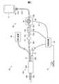
図1は、液体噴射装置20の構成を概略的に示す。液体噴射装置20は、医療機関において利用される医療機器であり、患部に対して液体を噴射することによって、患部を切除する機能を有する。 FIG. 1 schematically shows the configuration of the liquid ejecting
液体噴射装置20は、制御装置30と、アクチュエーター用ケーブル31と、ポンプ用ケーブル32、フットスイッチ35と、吸引装置40と、吸引チューブ41と、液体供給装置50と、ハンドピース100とを備える。 The
液体供給装置50は、給水バッグ51と、スパイク針52と、第1〜第5コネクター53a〜53eと、第1〜第4給水チューブ54a〜54dと、ポンプチューブ55と、閉塞検出機構56と、フィルター57とを備える。ハンドピース100は、ノズルユニット200と、アクチュエーターユニット300とを備える。ノズルユニット200は、噴射管205と、吸引管400とを備える。 The
給水バッグ51は、透明な合成樹脂製であり、内部に液体(具体的には生理食塩水)が充填されている。なお、本願では、水以外の液体が充填されていても、給水バッグ51と呼ぶ。スパイク針52は、第1コネクター53aを介して、第1給水チューブ54aに接続されている。給水バッグ51にスパイク針52が刺されると、給水バッグ51に充填された液体が第1給水チューブ54aに供給可能な状態になる。 The
第1給水チューブ54aは、第2コネクター53bを介して、ポンプチューブ55に接続されている。ポンプチューブ55は、第3コネクター53cを介して、第2給水チューブ54bに接続されている。チューブポンプ60は、ポンプチューブ55を、ステーターとローターとで挟み込んでいる。チューブポンプ60は、内蔵するモーターの回転によって、複数のローラーを回転させることで、ポンプチューブ55を扱(しご)く。このように扱かれることによって、ポンプチューブ55内の液体は、第1給水チューブ54a側から、第2給水チューブ54b側に送り出される。 The first
閉塞検出機構56は、第2給水チューブ54b内の圧力を測定することで、第1〜第4給水チューブ54a〜54d及びハンドピース100内の閉塞を検出する。閉塞検出機構56は、閉塞を検出すると、制御装置30に検出結果を入力する。 The
第2給水チューブ54bは、第4コネクター53dを介して、第3給水チューブ54cに接続されている。第3給水チューブ54cにはフィルター57が接続されている。フィルター57は、液体に含まれる異物を捕集する。 The second
第3給水チューブ54cは、第5コネクター53eを介して、第4給水チューブ54dに接続されている。第4給水チューブ54dは、ハンドピース100に接続されている。第4給水チューブ54dを通じてハンドピース100に供給された液体は、アクチュエーターユニット300の駆動によって、噴射管205の先端に設けられたノズル207から間欠的に噴射される。このように液体が間欠的に噴射されることによって、少ない流量で切除能力が確保できる。 The third
噴射管205及び吸引管400は、噴射管205を内管、吸引管400を外管とする二重管を構成する。吸引チューブ41は、ノズルユニット200に接続されている。吸引装置40は、吸引チューブ41を通じて、吸引管400内を吸引する。この吸引によって、吸引管400の先端付近の液体や切除片などが吸引される。 The
制御装置30は、CPUと記憶媒体とを備える。記憶媒体には、チューブポンプ60及び圧電素子360を制御するためのプログラムが記憶されている。制御装置30は、CPUがこのプログラムを実行することによって、フットスイッチ35が踏まれている間、アクチュエーター用ケーブル31を介して第1駆動信号を送信し、ポンプ用ケーブル32を介して第2駆動信号を送信する。第1駆動信号は、本実施形態においては400Hzの周期性を有し、アクチュエーターユニット300を駆動させる。第2駆動信号は、チューブポンプ60を駆動させる。よって、ユーザーがフットスイッチ35を踏んでいる間は液体が間欠的に噴射され、ユーザーがフットスイッチ35を踏んでいない間は液体の噴射が停止する。以下、単に駆動信号といえば、第1駆動信号のことを意味する。 The
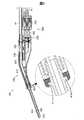
図2は、ハンドピース100の断面を示す。第4給水チューブ54dは、ハンドピースケース210内部でU字状に屈曲し、入口流路241に接続されている。入口流路241は、液体室240(図4参照)を介して、噴射管205に通じている。 FIG. 2 shows a cross section of the
入口流路241の流路径は、噴射管205の流路径よりも小さい。このため、液体室240内の圧力が変動しても(後述)、液体室240内の液体が入口流路241に逆流することが抑制される。 The channel diameter of the
ハンドピースケース210は、先端に凹部211を備える。吸引管400の装着は、凸部410が凹部211に嵌合することで実現される。装着された吸引管400は、吸引流路部230に通じている。吸引流路部230は、吸引力調整機構500を介して、吸引チューブ41に接続されている。 The
ユーザーは、孔522を利用して、吸引管400による吸引力の調整ができる。具体的には、孔522が開放されている面積を小さくすれば、孔522から流入する空気の流量も小さくなるので、吸引管400を介して吸引される流体(空気や液体等)の流量が大きくなる。つまり、吸引管400による吸引力が大きくなる。逆に、孔522が開放されている面積を大きくすれば、孔522から流入する空気の流量も大きくなるので、吸引管400による吸引力が小さくなる。通常、ユーザーは、孔522の開放面積の調整を、親指によって孔522を塞ぐ面積を調整することによって実現する。孔522が全く覆われていない状態では、吸引管400による吸引力が微小になるように、又は吸引力が全く作用しないように、孔522の形状が設計されている。本実施形態においては、吸引管400の流路面積が孔522の開口面積より大きいものの、吸引管400の長さを孔522の長さよりも長くすることで吸引管400の流路抵抗を孔522の流路抵抗よりも大きくしている。こうすることで孔522が全く覆われていない場合に、吸引管400による吸引力を微小とすることができる。 The user can adjust the suction force by the
アクチュエーターユニット300は、図2に示すように、ノズルユニット200のジョイント部250に取り付けられている。アクチュエーターユニット300は、ジョイント部250に対して脱着できるように構成されている。 As shown in FIG. 2, the
図3は、ジョイント部250及びアクチュエーターユニット300付近を拡大して示す断面図である。図4は、ジョイント部250の内部に設けられた液体室240付近を拡大した断面を示す。 FIG. 3 is an enlarged cross-sectional view showing the vicinity of the
駆動部350は、ハウジング351と、固定部材353と、圧電素子360と、可動板361とを備える。ハウジング351は、円筒状の部材である。可動板361は、ピストン362と、駆動側ダイヤフラム364とを含む。 The
圧電素子360は、積層型圧電素子である。圧電素子360は、伸縮する方向がハウジング351の長手方向に沿うように、ハウジング351内に配置されている。 The
固定部材353は、ハウジング351の一端に固定されている。圧電素子360は、固定部材353に接着剤によって固定されている。 The fixing
駆動側ダイヤフラム364の素材は、金属であり、具体的にはステンレス鋼であり、さらに具体的にはSUS304又はSUS316Lである。駆動側ダイヤフラム364は、圧電素子360のプリロードを実施するために厚めに形成される(例えば300μm)。また、圧電素子360が金属製で、且つ厚めに形成されているので、ピストン362に押された際に、滑らかに湾曲する。このため、液体室側ダイヤフラム260も滑らかに変形させることができる。 The material of the
駆動側ダイヤフラム364は、ハウジング351の他端を覆うように配置され、ハウジング351に溶接によって固定されている。 The
ピストン362は、圧電素子360の一端に接着剤によって固定されていると共に、駆動側ダイヤフラム364に接触するように配置されている。ピストン362は、異なる径の円柱が、同心円として積層したような形状をしている。小さい径の方が、駆動側ダイヤフラム364と接触している。このため、駆動側ダイヤフラム364は、端の方が押されず、溶接箇所には大きな力が作用しないようになっている。ピストン362及び駆動側ダイヤフラム364は、接着剤等によって固定されてはおらず、接触しているのみである。 The
ハウジング351の外周には、雄ネジ部351aが設けられている。雄ネジ部351aを、ジョイント部250に設けられた雌ネジに締め付けることで、ハウジング351がジョイント部250に固定されている。雌ネジを緩めることによって、ハウジング351をジョイント部250から取り外すことができる。 A
連結部310は、第1ケース311と、第2ケース312と、第3ケース313と、保持部材314と、金属板315と、第1ネジ316と、第2ネジ317と、第3ネジ318とを備える。なお金属板315は中継基板315と言い換えることもできる。 The connecting
第1ケース311は、第1ネジ316によって、固定部材353に固定されている。第2ケース312は、第2ネジ317と第3ネジ318とによって、第1ケース311に固定されている。2枚の金属板315は、第1ケース311内に挿入(収容)されている。 The
保持部材314は、アクチュエーター用ケーブル31の端部付近に加締められることによって固定されている。第3ケース313は、第2ケース312と保持部材314とを連結するための部材である。第3ケース313は、保持部材314の外径が膨らんだ部位を引っ掛けた状態で、第2ケース312に固定されている。 The holding
アクチュエーター用ケーブル31は、上記のように固定された状態で、2枚の金属板315と導通するように接続される。金属板315は、圧電素子360の正極、負極それぞれに、配線(図示しない)によって接続される。 The
圧電素子360は、アクチュエーター用ケーブル31、金属板315及び上記の配線を介して入力される駆動信号に応じて伸縮する。圧電素子360が伸縮すると、ピストン362が圧電素子360の長手方向に振動する。ピストン362が振動すると、駆動側ダイヤフラム364は、この振動に追従して変形する。 The
図4に示すように、液体室240は、窪み244に、液体室側ダイヤフラム260が覆い被さることで形成される。窪み244は、ジョイント部250において、薄く円形状に窪んだ部位である。液体室側ダイヤフラム260は、圧電素子360の伸縮に応じて変形しやすいように、駆動側ダイヤフラム364よりも薄く形成される(例えば50〜100μm)。液体室側ダイヤフラム260は、直径が13〜15mmであり、ジョイント部250に溶接によって固定されている。液体室側ダイヤフラム260の素材は、金属であり、具体的にはステンレス鋼であり、さらに具体的にはSUS304又はSUS316Lである。 As shown in FIG. 4, the
図4に示すように、液体室側ダイヤフラム260は、駆動側ダイヤフラム364に接触している。このため、先述したように駆動側ダイヤフラム364が変形すると、液体室側ダイヤフラム260も同様に変形する。 As shown in FIG. 4, the liquid
駆動側ダイヤフラム364が変形すると、液体室240の容積が変動する。この変動によって、液体室240内に満たされた液体の圧力が変動する。液体室240内の圧力が低下した際には、入口流路241から液体が液体室240に流入する。液体室240内の圧力が上昇した際には、液体が液体室240から噴射管205に流出する。噴射管205に流出した液体は、噴射管205の先端から噴射される。液体室240内の圧力が上昇するのは間欠的なので、噴射管205からの液体の噴射は間欠的に実施される。 When the
上記のように、液体室側ダイヤフラム260及び駆動側ダイヤフラム364は、一体となって変形する。つまり、液体室側ダイヤフラム260及び可動板361は、一体となって変形する。図4に示された符号460は、このように一体となって変形する液体室側ダイヤフラム260と可動板361とを合わせた合成ダイヤフラム460を示す。合成ダイヤフラム460は、1つのダイヤフラムと捉えることができる。 As described above, the liquid
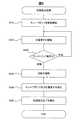
図5は、初期設定処理を示すフローチャートである。制御装置30は、内蔵する記憶媒体に記憶されたプログラムを実行することによって、初期設定処理を実行する。制御装置30は、初期設定の指示を受けたことを契機に、初期設定処理を実行する。制御装置30は、初期設定の指示を受けるための入力インターフェースとして、筐体の表面にボタンを備える。 FIG. 5 is a flowchart showing the initial setting process. The
まず、チューブポンプ60の駆動を開始する(S610)。次に、圧電素子360の駆動を開始する(S620)。続いて、判定期間のフィードバック電流の波形(以下、判定電流という)が、平坦なのか振動しているのかを判定する(S630)。 First, driving of the
圧電素子360等の電歪効果を有する素子においては、圧電素子360が伸縮した際に液体室240内の流体及び合成ダイヤフラム460から受ける反力に応じた逆起電力が発生する。その結果、圧電素子360には、入力された駆動信号と、反力に応じた逆起電力とによって決定される電流(電荷)が流れ込む。当然ながら、液体室240に液体が充填された状態と、充填されていない状態とでは圧電素子360が受ける反力は異なるから、発生する逆起電力も異なって、圧電素子360に流れ込む電流(フィードバック電流)も異なったものとなる。従って、液体室240に液体が充填された状態と、充填されていない状態とではフィードバック電流を検出した場合の電流波形が相違する。この電流波形の違いから、液体室240に液体が充填されたか否かを判定することができる。 In an element having an electrostrictive effect, such as the
本実施形態においては、圧電素子360の伸縮は、圧電素子360に駆動信号が入力された場合に発生するので、フィードバック電流は、駆動信号が入力された圧電素子360から得られる。制御装置30は、アクチュエーター用ケーブル31を介して、フィードバック電流を取得する。 In the present embodiment, the expansion and contraction of the
図6及び図7は、駆動信号の1周期分についての駆動信号の電圧値(以下、駆動電圧)及びフィードバック電流の変化を示す。図6は、判定電流が平坦である場合を示す。図7は、判定電流が振動している場合を示す。図6及び図7に示すように、上記の判定期間とは、駆動電圧の急激な下降が終了した後から所定時間後までの期間のことである。判定期間においては、駆動電圧の変動は小さい。 6 and 7 show changes in the voltage value of the drive signal (hereinafter referred to as drive voltage) and the feedback current for one cycle of the drive signal. FIG. 6 shows a case where the determination current is flat. FIG. 7 shows a case where the determination current is oscillating. As shown in FIGS. 6 and 7, the determination period is a period from the end of the rapid decrease in the drive voltage to a predetermined time. In the determination period, the fluctuation of the drive voltage is small.
図6及び図7に示すように、駆動電圧が大きく変動する期間においては、フィードバック電流は大きく振動する。駆動電圧が大きく変動する期間とは、駆動電圧が急激に上昇する期間と、急激に下降する期間とを含む期間である。 As shown in FIGS. 6 and 7, the feedback current greatly oscillates during the period in which the drive voltage varies greatly. The period in which the driving voltage fluctuates greatly is a period including a period in which the driving voltage rapidly increases and a period in which the driving voltage rapidly decreases.
一方、判定期間においては、フィードバック電流が平坦であったり、振動したりする。この差異をもたらすのは、圧電素子360の伸縮に対する反力の大きさの違いである。反力の大きさの違いをもたらす主な原因は、液体室240が充填状態なのか非充填状態なのかの違いである。充填状態とは、液体室240が液体で充填されている状態である。非充填状態とは、液体室240が液体で充填されていない状態である。液体室240に液体が充填されていれば反力が大きくなり、液体室240に液体が充填されていなければ反力は小さくなる。 On the other hand, in the determination period, the feedback current is flat or vibrates. This difference is caused by the difference in the magnitude of the reaction force with respect to the expansion and contraction of the
上記S630は、上記の現象を利用して、給水バッグ51から流出した液体が、液体室240に到達することで、非充填状態から充填状態に移行したことを検出するためのステップである。 S630 is a step for detecting that the liquid that has flowed out of the
S630の判定は、判定期間における電流値の最大値と最小値との差が基準値以上か否かという基準で実現する。 The determination in S630 is realized based on whether or not the difference between the maximum value and the minimum value of the current value in the determination period is greater than or equal to a reference value.
判定電流が平坦である場合(S630、平坦)、S620に戻る。この結果、判定電流が平坦である期間は、圧電素子360に対して連続的に駆動信号が入力され、S630の判定も連続的に実行される。 When the determination current is flat (S630, flat), the process returns to S620. As a result, during a period in which the determination current is flat, a drive signal is continuously input to the
一方、判定電流が振動している場合(S630、振動)、液体室240に液体が充填されたと推定し、泡除去運転を実施する(S640)。泡除去運転とは、液体室240に混入した気泡を除去するための運転である。具体的には、チューブポンプ60による供給流量を増大させ、圧電素子360の駆動信号の電圧値および周波数を増大させる。 On the other hand, when the determination current vibrates (S630, vibration), it is estimated that the
泡除去運転を一定時間、実施すると、所定条件が満たされる。所定条件とは、液体室240に液体が充填されたことと、泡除去運転の終了との両方が満たされることである。所定条件が満たされれば、液体室240だけでなく噴射管205の先端まで、ほぼ確実に液体が充填される。 When the bubble removal operation is performed for a certain time, the predetermined condition is satisfied. The predetermined condition is that both the
上記のようにして所定条件が満たされると、チューブポンプ60及び圧電素子360を停止させる(S650)。そして、初期設定が完了したことを、ユーザーに報知して(S660)、初期設定処理を終える。制御装置30は、上記報知として、音および光を出力する。音とは、「初期設定が完了しました」等の音声などである。光とは、制御装置30の表面に設けられたLEDランプの発光などである。このLEDランプの近傍には「初期設定完了」等の文字が記されている。 When the predetermined condition is satisfied as described above, the
図8は、異常検出処理を示すフローチャートである。制御装置30は、初期設定処理を終了した後、異常検出処理を開始する。 FIG. 8 is a flowchart showing the abnormality detection process. The
まず、フットスイッチ35がONである(踏まれている)かを判定する(S710)。フットスイッチ35が踏まれていない場合(S710,NO)、S710を繰り返す。 First, it is determined whether the
フットスイッチ35が踏まれている場合(S710,YES)、判定電流が、平坦なのか振動しているのかを判定する(S730)。判定電流が振動している場合(S730,振動)、S710に戻る。判定電流が振動している場合は充填状態であるので、初期設定処理後においては正常な状態である。 When the
判定電流が平坦である場合(S730,平坦)、圧電素子360を停止させる(S750)。判定電流が平坦である場合は非充填状態であるので、初期設定処理後においては異常な状態である。そこで、圧電素子360を停止させる(S750)。 If the determination current is flat (S730, flat), the
続いて、非充填状態であることをユーザーに報知して(S760)、異常検出処理を終える。上記報知として、音および光を出力する。音とは、「液体が供給されていません」等の音声などである。光とは、制御装置30の表面に設けられたLEDランプの発光である。このLEDランプの近傍には「異常発生」等の文字が記されている。 Subsequently, the user is informed that the state is not filled (S760), and the abnormality detection process is finished. Sound and light are output as the notification. The sound is a sound such as “no liquid is supplied”. The light is light emission of the LED lamp provided on the surface of the
以上に説明した実施形態によれば、初期設定による充填状態への移行を検出し次第、泡除去処理に移行できるので、必要十分な時間および液体の供給量で初期設定を完了できる。さらに、初期設定の完了をユーザーに報知するので、ユーザーは、初期設定が完了し次第、液体噴射装置20の使用を開始できる。
また、何らかの不具合で充填状態に移行できない場合にも、その状態をユーザーが認識することができる。According to the embodiment described above, since the transition to the bubble removal process can be performed as soon as the transition to the filling state by the initial setting is detected, the initial setting can be completed in the necessary and sufficient time and the liquid supply amount. Furthermore, since the completion of the initial setting is notified to the user, the user can start using the
In addition, even when it is not possible to shift to the filling state due to some trouble, the user can recognize the state.
実施形態2を説明する。実施形態2の説明は、主に実施形態1と異なる点を対象とする。よって、特に説明がない点については実施形態1と同じである。 A second embodiment will be described. The description of the second embodiment is mainly directed to differences from the first embodiment. Therefore, the points not specifically described are the same as those in the first embodiment.
図9は、実施形態2における初期設定処理を示すフローチャートである。実施形態2では、S615とS635とが追加されている。 FIG. 9 is a flowchart illustrating an initial setting process according to the second embodiment. In the second embodiment, S615 and S635 are added.
S615は、S610の後、所定時間、待機するステップである。S620は、S615による待機後に実行する。つまり、圧電素子の駆動(S620)及び充填状態かの判定(S630)を間欠的に実行する。 S615 is a step of waiting for a predetermined time after S610. S620 is executed after waiting in S615. That is, the driving of the piezoelectric element (S620) and the determination of whether or not it is filled (S630) are executed intermittently.
このようにS620の開始をS610の所定時間後にするのは、S610の直後は、液体室240が非充填状態である可能性が高いからである。従って、S610の直後にS620,S630を実行する必要性に乏しい。そこで、圧電素子360を無駄に駆動させることを避けるために、S615を実行する。 The reason for starting S620 in this way after the predetermined time of S610 is that there is a high possibility that the
S635は、S630で、判定電流が平坦であると判定した後、所定時間、待機するステップである。S635の所定時間は、S615の所定時間と同じ長さの時間でもよいし、異なる長さの時間でもよい。 S635 is a step of waiting for a predetermined time after determining that the determination current is flat in S630. The predetermined time of S635 may be the same time as the predetermined time of S615 or may be a different length of time.
このようにして、判定電流が平坦であると判定した後、S630を再び実行するまでの間隔を延ばすのは、判定電流が平坦であると判定した直後にS630を再び実行しても、判定結果は同じである可能性が高いからである。給水バッグ51から排出された液体が液体室240に到達するまでの時間は、駆動信号の周期に比べて十分に長い時間だからである。 In this way, after determining that the determination current is flat, the interval until S630 is executed again is increased even if S630 is executed again immediately after determining that the determination current is flat. Is likely to be the same. This is because the time until the liquid discharged from the
また、充填状態に移行したことの検出が、実際に充填状態に移行した時点から少し遅れても、特段の支障は無い。そこで、S635によって、圧電素子360の駆動と、フィードバック電流の検出との実行頻度を低下させる。 In addition, even if the detection of the transition to the filling state is slightly delayed from the time of the actual transition to the filling state, there is no particular problem. Therefore, in S635, the execution frequency of driving the
実施形態2によれば、実施形態1の効果に加え、非充填状態で圧電素子360を駆動する時間を短くできるので、圧電素子360の負荷を低減や節電を実現できる。 According to the second embodiment, in addition to the effects of the first embodiment, the time for driving the
なお、各実施形態においては判定期間のフィードバック電流が平坦なのか振動しているのかを判定することとしたが、これに限定されるものではない。充填状態または非充填状態に応じた特徴的な電流の大きさや形状を用いることができる場合には、それらの特徴量の検出有無を用いて判定を実行してもよい。例えば、判定期間における電流のピーク値を用いてもよいし、電流値が所定の値まで減衰するまでの時間を用いてもよい。 In each embodiment, it is determined whether the feedback current in the determination period is flat or oscillating, but the present invention is not limited to this. When characteristic current magnitudes and shapes according to the filling state or the non-filling state can be used, the determination may be performed using the presence / absence of detection of the feature amounts. For example, the peak value of the current in the determination period may be used, or the time until the current value decays to a predetermined value may be used.
本発明は、本明細書の実施形態や実施例、変形例に限られるものではなく、その趣旨を逸脱しない範囲において種々の構成で実現できる。例えば、発明の概要の欄に記載した各形態中の技術的特徴に対応する実施形態、実施例、変形例中の技術的特徴は、先述の課題の一部又は全部を解決するために、或いは、先述の効果の一部又は全部を達成するために、適宜、差し替えや、組み合わせを行うことができる。その技術的特徴が本明細書中に必須なものとして説明されていなければ、適宜、削除できる。例えば、以下のものが例示される。 The present invention is not limited to the embodiments, examples, and modifications of the present specification, and can be implemented with various configurations without departing from the spirit of the present invention. For example, the technical features in the embodiments, examples, and modifications corresponding to the technical features in the embodiments described in the summary section of the invention are to solve some or all of the above-described problems, or In order to achieve part or all of the effects described above, replacement or combination can be performed as appropriate. If the technical feature is not described as essential in this specification, it can be deleted as appropriate. For example, the following are exemplified.
上記実施形態において、ソフトウエアによって実現された機能及び処理の一部又は全部は、ハードウエアによって実現されてもよい。また、ハードウエアによって実現された機能及び処理の一部又は全部は、ソフトウエアによって実現されてもよい。ハードウエアとしては、例えば、集積回路、ディスクリート回路、または、それらの回路を組み合わせた回路モジュールなど、各種回路を用いることができる。 In the above embodiment, some or all of the functions and processes realized by software may be realized by hardware. In addition, some or all of the functions and processes realized by hardware may be realized by software. As the hardware, for example, various circuits such as an integrated circuit, a discrete circuit, or a circuit module obtained by combining these circuits can be used.
チューブポンプを停止させるため及びユーザーに報知するための所定条件は、泡除去運転の終了を含まなくてもよい。つまり、充填状態に移行したことを所定条件としてもよい。この後、泡除去運転を実行してもよいし、しなくてもよい。 The predetermined condition for stopping the tube pump and notifying the user may not include the end of the bubble removal operation. In other words, the transition to the filling state may be set as a predetermined condition. Thereafter, the bubble removal operation may or may not be executed.
ノズルユニットとアクチュエーターユニットとが一体に構成されていてもよい。このように一体となって構成されたものを、アクチュエーターユニットと捉えてもよいし、ハンドピースと捉えてもよい。 The nozzle unit and the actuator unit may be integrally formed. What is integrally configured as described above may be regarded as an actuator unit or a hand piece.
ノズルユニットは、滅菌処理することで、複数回使用してもよい。
噴射する液体は、純水でもよいし薬液でもよい。
液体噴射装置は、医療機器以外に利用されてもよい。
例えば、液体噴射装置は、噴射した液体によって汚れを除去する洗浄装置に利用されてもよいし、噴射した液体によって線などを描く描画装置に利用されてもよい。The nozzle unit may be used multiple times by sterilization.
The liquid to be ejected may be pure water or a chemical solution.
The liquid ejecting apparatus may be used other than medical equipment.
For example, the liquid ejecting apparatus may be used in a cleaning apparatus that removes dirt with the ejected liquid, or may be used in a drawing apparatus that draws a line or the like with the ejected liquid.
実施形態においては間欠的に液体を噴射する構成を採用したが、連続的に液体を噴射する機能を備えた構成を採用してもよい。例えば、間欠的な噴射と連続的な噴射とを使い分けることができる構成でもよい。実施形態のハードウエア構成を利用して連続的な噴射を実施するために、アクチュエーターの駆動を停止または低下させた状態でチューブポンプのみを駆動させてもよい。この構成の場合、間欠的な噴射を切除のために実施し、連続的な噴射を洗浄のために実施してもよい。
或いは、連続的な噴射のみが実施できる構成でもよい。この構成の場合、連続的な噴射によって切除を実施してもよい。
また、超音波を利用した超音波凝固切開装置や超音波吸引装置等の手術機器に用いられる液体噴射装置に適用しても良い。In the embodiment, the configuration in which the liquid is intermittently ejected is employed, but a configuration having a function of ejecting the liquid continuously may be employed. For example, the structure which can selectively use intermittent injection and continuous injection may be sufficient. In order to perform continuous injection using the hardware configuration of the embodiment, only the tube pump may be driven with the driving of the actuator stopped or reduced. In this configuration, intermittent spraying may be performed for excision and continuous spraying may be performed for cleaning.
Or the structure which can implement only continuous injection may be sufficient. In the case of this configuration, the ablation may be performed by continuous injection.
Further, the present invention may be applied to a liquid ejecting apparatus used for surgical equipment such as an ultrasonic coagulation / cutting apparatus and an ultrasonic suction apparatus using ultrasonic waves.
20…液体噴射装置、30…制御装置、31…アクチュエーター用ケーブル、32…ポンプ用ケーブル、35…フットスイッチ、40…吸引装置、41…吸引チューブ、50…液体供給装置、51…給水バッグ、52…スパイク針、53a…第1コネクター、53b…第2コネクター、53c…第3コネクター、53d…第4コネクター、53e…第5コネクター、54a…第1給水チューブ、54b…第2給水チューブ、54c…第3給水チューブ、54d…第4給水チューブ、55…ポンプチューブ、56…閉塞検出機構、57…フィルター、60…チューブポンプ、100…ハンドピース、200…ノズルユニット、205…噴射管、207…ノズル、210…ハンドピースケース、211…凹部、230…吸引流路部、240…液体室、241…入口流路、250…ジョイント部、260…液体室側ダイヤフラム、300…アクチュエーターユニット、310…連結部、311…第1ケース、312…第2ケース、313…第3ケース、314…保持部材、315…金属板、315…中継基板、316…第1ネジ、317…第2ネジ、318…第3ネジ、350…駆動部、351…ハウジング、351a…雄ネジ部、353…固定部材、360…圧電素子、361…可動板、362…ピストン、364…駆動側ダイヤフラム、400…吸引管、410…凸部、460…合成ダイヤフラム、500…吸引力調整機構、522…孔DESCRIPTION OF
Claims (9)
Translated fromJapanese前記噴射管に通じる液体室と、
駆動信号が入力されると、前記液体室の容積を変更する圧電素子と、
前記液体室に前記液体を供給するために回転するチューブポンプと、
前記液体室に前記液体が充填されていない非充填状態から、前記液体室に前記液体が充填されている充填状態に移行したことを、前記駆動信号が入力された前記圧電素子から得られるフィードバック電流に基づき検出する充填検出を実行する制御装置と、
を備える液体噴射装置。An injection tube for injecting liquid;
A liquid chamber leading to the jet tube;
When a drive signal is input, a piezoelectric element that changes the volume of the liquid chamber;
A tube pump that rotates to supply the liquid to the liquid chamber;
A feedback current obtained from the piezoelectric element to which the drive signal has been input indicates that the liquid chamber has changed from an unfilled state in which the liquid is not filled to a filled state in which the liquid chamber is filled with the liquid. A control device for performing filling detection based on
A liquid ejecting apparatus comprising:
請求項1に記載の液体噴射装置。The liquid ejecting apparatus according to claim 1, wherein the control device continuously performs the filling detection.
請求項1に記載の液体噴射装置。The liquid ejecting apparatus according to claim 1, wherein the control device intermittently executes the filling detection.
請求項1から請求項3までの何れか一項に記載の液体噴射装置。4. The liquid ejecting apparatus according to claim 1, wherein the control device starts the filling detection after a predetermined time from the start of rotation of the tube pump.
請求項1から請求項4までの何れか一項に記載の液体噴射装置。The liquid ejecting apparatus according to any one of claims 1 to 4, wherein the control device detects that the state has shifted from the filling state to the non-filling state based on the feedback current.
請求項1から請求項5までの何れか一項に記載の液体噴射装置。The liquid according to any one of claims 1 to 5, wherein the control device stops the tube pump when a predetermined condition including transition from the non-filling state to the filling state is satisfied. Injection device.
請求項1から請求項5までの何れか一項に記載の液体噴射装置。The said control apparatus alert | reports to a user that it shifted to the said filling state, when predetermined conditions including having shifted to the said filling state from the said non-filling state are satisfy | filled. The liquid ejecting apparatus according to one item.
前記液体室に液体を供給するために回転するチューブポンプと、
を制御する制御装置に実行させるためのプログラムであって、
前記液体室に前記液体が充填されていない非充填状態から充填されている充填状態に移行したことを、前記駆動信号が入力された前記圧電素子から得られるフィードバック電流に基づき検出する
ためのプログラム。When a driving signal is input, a piezoelectric element that changes the volume of the liquid chamber that communicates with the ejection tube;
A tube pump that rotates to supply liquid to the liquid chamber;
A program for causing a control device to control
A program for detecting, based on a feedback current obtained from the piezoelectric element to which the drive signal is input, that the liquid chamber is shifted from an unfilled state in which the liquid is not filled to a filled state in which the liquid is filled.
前記液体室に液体を供給するために回転するチューブポンプと、
を制御する制御装置であって、
前記液体室に前記液体が充填されていない非充填状態から充填されている充填状態に移行したことを、前記駆動信号が入力された前記圧電素子から得られるフィードバック電流に基づき検出する
制御装置。When a driving signal is input, a piezoelectric element that changes the volume of the liquid chamber that communicates with the ejection tube;
A tube pump that rotates to supply liquid to the liquid chamber;
A control device for controlling
A control device that detects, based on a feedback current obtained from the piezoelectric element to which the drive signal is input, that the liquid chamber has shifted from an unfilled state in which the liquid is not filled to a filled state in which the liquid is filled.
Priority Applications (1)
| Application Number | Priority Date | Filing Date | Title |
|---|---|---|---|
| JP2015235446AJP2017100082A (en) | 2015-12-02 | 2015-12-02 | Liquid injection device, program and control unit |
Applications Claiming Priority (1)
| Application Number | Priority Date | Filing Date | Title |
|---|---|---|---|
| JP2015235446AJP2017100082A (en) | 2015-12-02 | 2015-12-02 | Liquid injection device, program and control unit |
Publications (1)
| Publication Number | Publication Date |
|---|---|
| JP2017100082Atrue JP2017100082A (en) | 2017-06-08 |
Family
ID=59015263
Family Applications (1)
| Application Number | Title | Priority Date | Filing Date |
|---|---|---|---|
| JP2015235446APendingJP2017100082A (en) | 2015-12-02 | 2015-12-02 | Liquid injection device, program and control unit |
Country Status (1)
| Country | Link |
|---|---|
| JP (1) | JP2017100082A (en) |
Cited By (1)
| Publication number | Priority date | Publication date | Assignee | Title |
|---|---|---|---|---|
| CN117042369A (en)* | 2023-08-29 | 2023-11-10 | 浙江原启工程有限公司 | Wisdom road weak current equipment |
- 2015
- 2015-12-02JPJP2015235446Apatent/JP2017100082A/enactivePending
Cited By (2)
| Publication number | Priority date | Publication date | Assignee | Title |
|---|---|---|---|---|
| CN117042369A (en)* | 2023-08-29 | 2023-11-10 | 浙江原启工程有限公司 | Wisdom road weak current equipment |
| CN117042369B (en)* | 2023-08-29 | 2024-03-26 | 浙江原启工程有限公司 | Wisdom road weak current equipment |
Similar Documents
| Publication | Publication Date | Title |
|---|---|---|
| JP5082049B2 (en) | Fluid ejecting apparatus and surgical tool | |
| CN101991455B (en) | Fluid ejection device and method to control fluid ejection device | |
| JP4666094B2 (en) | PULSE FLOW GENERATION DEVICE, MEDICAL DEVICE, AND METHOD OF CONTROLLING PULSE FLOW GENERATION DEVICE | |
| JP5862020B2 (en) | Fluid ejection device | |
| JP5320906B2 (en) | Fluid ejection surgical instrument and fluid ejection method | |
| JP2015200287A (en) | Fluid injection device | |
| JP2010077948A (en) | Fluid injection device, and control method of fluid injection device | |
| JP2010059792A (en) | Fluid injection device, fluid injection unit, control device, method of controlling fluid injection device and operating device | |
| JP2015198861A (en) | Fluid ejecting apparatus and fluid ejecting method | |
| JP2017100082A (en) | Liquid injection device, program and control unit | |
| JP2010051896A (en) | Fluid jetting device, fluid jetting surgical device, and fluid jetting method | |
| JP6186831B2 (en) | Liquid ejector | |
| JP2017136224A (en) | Fluid injection device | |
| JP2015054026A (en) | Liquid injection device, medical equipment | |
| JP5782763B2 (en) | Fluid ejection device | |
| WO2016174873A1 (en) | Liquid supply device and medical device, and method for diagnosing failure in liquid supply device | |
| JP2017101598A (en) | Liquid ejecting device, program, control device | |
| US9566796B2 (en) | Liquid supply device and liquid ejection device | |
| JP2016176457A (en) | Actuator unit for liquid injection device and hand piece for liquid injection device | |
| JP2016174892A (en) | Liquid supply device, liquid ejection device | |
| JP2015198863A (en) | Fluid ejection device | |
| JP2015054029A (en) | Liquid injection device, medical equipment | |
| CN107126247A (en) | Operation handpiece, liquid injection apparatus, suction device | |
| JP5636809B2 (en) | Liquid ejector | |
| CN107126248A (en) | Operation handpiece, liquid injection apparatus, suction device |