JP2017093044A - Power converter and synchronous motor - Google Patents
Power converter and synchronous motorDownload PDFInfo
- Publication number
- JP2017093044A JP2017093044AJP2015216741AJP2015216741AJP2017093044AJP 2017093044 AJP2017093044 AJP 2017093044AJP 2015216741 AJP2015216741 AJP 2015216741AJP 2015216741 AJP2015216741 AJP 2015216741AJP 2017093044 AJP2017093044 AJP 2017093044A
- Authority
- JP
- Japan
- Prior art keywords
- field winding
- voltage
- synchronous motor
- temperature
- input
- Prior art date
- Legal status (The legal status is an assumption and is not a legal conclusion. Google has not performed a legal analysis and makes no representation as to the accuracy of the status listed.)
- Granted
Links
- 230000001360synchronised effectEffects0.000titleclaimsabstractdescription65
- 238000004804windingMethods0.000claimsabstractdescription115
- 238000006243chemical reactionMethods0.000claimsabstractdescription27
- 238000001514detection methodMethods0.000claimsabstractdescription17
- 238000012544monitoring processMethods0.000abstractdescription4
- 230000007274generation of a signal involved in cell-cell signalingEffects0.000description6
- 238000005096rolling processMethods0.000description6
- 238000009499grossingMethods0.000description5
- 230000002159abnormal effectEffects0.000description3
- 230000005856abnormalityEffects0.000description2
- 238000010586diagramMethods0.000description2
- 230000000694effectsEffects0.000description2
- RYGMFSIKBFXOCR-UHFFFAOYSA-NCopperChemical compound[Cu]RYGMFSIKBFXOCR-UHFFFAOYSA-N0.000description1
- XEEYBQQBJWHFJM-UHFFFAOYSA-NIronChemical group[Fe]XEEYBQQBJWHFJM-UHFFFAOYSA-N0.000description1
- 239000003990capacitorSubstances0.000description1
- 229910052802copperInorganic materials0.000description1
- 239000010949copperSubstances0.000description1
- 230000004907fluxEffects0.000description1
- 230000007257malfunctionEffects0.000description1
- 239000000463materialSubstances0.000description1
- 238000012986modificationMethods0.000description1
- 230000004048modificationEffects0.000description1
Images
Landscapes
- Control Of Ac Motors In General (AREA)
Abstract
Translated fromJapaneseDescription
Translated fromJapanese本発明の実施形態は、電力変換装置および同期電動機に関する。 Embodiments described herein relate generally to a power converter and a synchronous motor.
製鐵所の圧延プラントを構成する機器の一つに電動機があり、そのうち主機駆動用大形電動機は、圧延プラントにおける重要な電気設備である。主機駆動大形電動機は、一度大きな故障が発生すると、圧延を継続することができず、圧延プラント自体の操業が停止してしまう。このように、電動機の故障が圧延プラント全体に影響するため、安定した圧延プラントの操業のためには、各電動機の状態を監視することにより、電動機の異常を早期に発見する必要がある。電動機の異常を発見することができれば、電動機の故障を未然に防止することが可能になる。 One of the equipment that constitutes the rolling mill of a steelworks is an electric motor, and a large electric motor for driving a main machine is an important electrical facility in the rolling plant. Once a major failure occurs in the main motor-driven large electric motor, rolling cannot be continued and the operation of the rolling plant itself is stopped. Thus, since the failure of the electric motor affects the entire rolling plant, it is necessary to detect the abnormality of the electric motor early by monitoring the state of each electric motor for stable operation of the rolling plant. If the abnormality of the electric motor can be found, it becomes possible to prevent the electric motor from being broken.
主機駆動用大形電動機には、大形化が容易なことから同期電動機が用いられることが多い。一般的に、同期電動機の状態の監視を行う場合には、固定子巻線に取り付けられた温度検出器によって固定子巻線の温度を監視する。これによって、過負荷等により固定子巻線が異常な温度となっているかどうかを監視することができる。固定子巻線の温度は、同期電動機に供給される交流電流の増加に伴って上昇するので、固定子巻線の温度を監視することによって、固定子巻線に流れる交流電流を合わせて監視することもできる。 Synchronous motors are often used for large motors for driving main machines because they can be easily increased in size. Generally, when monitoring the state of the synchronous motor, the temperature of the stator winding is monitored by a temperature detector attached to the stator winding. This makes it possible to monitor whether the stator winding is at an abnormal temperature due to overload or the like. Since the temperature of the stator winding rises as the alternating current supplied to the synchronous motor increases, by monitoring the temperature of the stator winding, the alternating current flowing through the stator winding is also monitored. You can also.
同期電動機は、回転子に設けられた界磁巻線を有しており、同期電動機の異常状態の有無を把握するために、同期電動機の運転時において界磁巻線の温度監視することが望まれている。しかしながら、界磁巻線は、回転子に設けられているため、運転状態の同期電動機では、界磁巻線上に取り付けた温度検出器の配線を引き出すことができない。そのため、界磁巻線の温度検出を行う場合には同期電動機を停止させなければならず、プラント操業の円滑な運営の観点から実現することは困難である。 The synchronous motor has a field winding provided on the rotor, and it is desirable to monitor the temperature of the field winding during operation of the synchronous motor in order to grasp the presence or absence of an abnormal state of the synchronous motor. It is rare. However, since the field winding is provided in the rotor, the wiring of the temperature detector attached on the field winding cannot be pulled out by the synchronous motor in the operating state. Therefore, when detecting the temperature of the field winding, the synchronous motor must be stopped, which is difficult to realize from the viewpoint of smooth operation of the plant operation.
実施形態は、電動機運転時においても界磁巻線温度を適切に測定し、監視することができる電力変換装置および同期電動機を提供する。 The embodiment provides a power conversion device and a synchronous motor that can appropriately measure and monitor the field winding temperature even during motor operation.
実施形態に係る電力変換装置は、ブラシ付き同期電動機を駆動する電力変換装置である。この電力変換装置は、界磁巻線を流れる電流を検出する電流検出部と、前記界磁巻線の温度を計算するためのデータを格納する記憶部と、前記データ、前記電流検出部によって検出された前記電流、およびブラシを介して検出された前記界磁巻線の両端の電圧である第1電圧にもとづいて、前記界磁巻線の温度を計算する演算部と、を備える。 The power converter device which concerns on embodiment is a power converter device which drives the synchronous motor with a brush. The power converter includes a current detection unit that detects a current flowing through the field winding, a storage unit that stores data for calculating the temperature of the field winding, and the data and the current detection unit. And an arithmetic unit that calculates the temperature of the field winding based on the current and the first voltage that is the voltage across the field winding detected through the brush.
実施形態の電力変換装置では、ブラシを介して界磁巻線の両端電圧を検出し、検出された界磁巻線の電圧等にもとづいて界磁巻線温度を計算する演算部を備えているので、同期電動機の運転状態における界磁巻線温度を監視することができる。そのため、より安全な運転を継続させることができる。 The power conversion device according to the embodiment includes a calculation unit that detects the voltage across the field winding via a brush and calculates the field winding temperature based on the detected voltage of the field winding. Therefore, the field winding temperature in the operating state of the synchronous motor can be monitored. Therefore, safer driving can be continued.
以下、図面を参照しつつ、本発明の実施形態について説明する。
なお、図面は模式的または概念的なものであり、各部分の厚みと幅との関係、部分間の大きさの比率などは、必ずしも現実のものと同一とは限らない。また、同じ部分を表す場合であっても、図面により互いの寸法や比率が異なって表される場合もある。
なお、本願明細書と各図において、既出の図に関して前述したものと同様の要素には、同一の符号を付して詳細な説明を適宜省略する。Hereinafter, embodiments of the present invention will be described with reference to the drawings.
The drawings are schematic or conceptual, and the relationship between the thickness and width of each part, the size ratio between the parts, and the like are not necessarily the same as actual ones. Further, even when the same part is represented, the dimensions and ratios may be represented differently depending on the drawings.
In the present specification and drawings, the same elements as those described above with reference to the previous drawings are denoted by the same reference numerals, and detailed description thereof is omitted as appropriate.
(第1の実施形態)
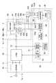
図1は、本実施形態に係る電力変換装置を例示するブロック図である。
図1に示すように、本実施形態の電力変換装置1は、界磁電流検出部36と、温度演算部37と、記憶部38と、を含む制御回路30を備える。電力変換装置1は、入力電源3と同期電動機2との間に接続されている。電力変換装置1は、入力端子1a〜1cを介して入力電源3に接続され、出力端子1d〜1fを介して同期電動機2に接続されている。入力電源3は、この例では三相交流電源である。入力電源3は、三相交流に限定されず、単相の商用電源であってもよく、直流電源であってもよい。電力変換装置1の出力は、同期電動機の端子40a〜40cを介して、固定子巻線40に電気的に接続されている。同期電動機2は、界磁巻線41の両端の電圧を出力する端子48a,48bを有しており、端子48a,48bを介して、電力変換装置1の制御回路30に電気的に接続されている。(First embodiment)
FIG. 1 is a block diagram illustrating a power conversion apparatus according to this embodiment.
As shown in FIG. 1, the
電力変換装置1は、入力電源3から電力の供給を受けて、交流電力を出力することによって同期電動機2を駆動する。電力変換装置1が同期電動機2に供給する交流電力は、たとえば、あらかじめ設定された電圧、電流および周波数を有しており、同期電動機2は、この交流電力によって速度制御等されて運転される。 The
電力変換装置1は、整流平滑回路を含んだインバータ装置である。電力変換装置1は、整流回路10と、平滑回路12と、主回路20と、をさらに含む。 The
整流回路10は、三相交流を出力する入力電源3に接続されている。整流回路10の出力には、平滑回路12を構成するコンデンサが接続されている。整流回路10に入力された三相交流電力は、直流電力に変換されて主回路20に出力される。 The
主回路20は、平滑回路12の出力に接続されている。主回路20は、整流平滑された直流電力を高周波でスイッチングしてPWM等によって所定の電圧、電流および周波数の交流電力に変換する。主回路20には、ブリッジ回路等出力電力や出力電圧等に合わせて適切な回路方式が選択される。 The
制御回路30は、主回路20、電力変換装置1の出力端子1d〜1f、および同期電動機2に接続されている。制御回路30は、界磁電流検出部36、温度演算部37および記憶部38のほか、電流制御回路31と、基準信号発生回路32と、ゲート駆動回路33と、界磁巻線整流回路34と、界磁制御回路35と、を含んでいる。制御回路30は、主回路20の出力電流を電流検出部22によって検出して、所定の交流電流が出力されるように制御する。制御回路30は、同期電動機2の電機子に印加される電圧に応じて同期電動機2の固定子巻線40に流れる電流を制御する。また、制御回路30は、同期電動機2の界磁巻線41に流れる界磁電流およびブラシ42a,42bから出力される電圧を入力して界磁巻線41の温度を推定する。 The
電流制御回路31は、主回路20の出力と、電力変換装置1から見た負荷である同期電動機2との間に直列に接続されている電流検出部22の出力に接続されている。電流制御回路31は、基準信号発生回路32の出力にも接続されている。電流制御回路31は、電流検出部22によって検出された電力変換装置1の出力電流と、基準信号発生回路32から出力される基準信号とを比較して、出力電流が基準信号に一致するように制御信号を出力する。ゲート駆動回路33は、電流制御回路31から出力された制御信号にしたがって、主回路20を構成するスイッチング素子の駆動信号を出力する。電流制御回路31は、たとえば直交座標変換回路および回転座標変換回路等を含んでおり、基準信号発生回路32およびゲート駆動回路33とともに、電力変換装置1の出力電流を、設定された波形で出力されるように制御する。 The
界磁巻線整流回路34は、端子30a,30bを介して、同期電動機2の界磁巻線41に接続されている。界磁巻線整流回路34の界磁巻線41への電気的接続は、ブラシ42a,42bおよびコレクタリング43a,43bを介して行われる。界磁巻線41およびコレクタリング43a,43bは、同期電動機2の回転子側に固定されるように設けられ、ブラシ42a、42bは、固定子側に固定されるように設けられている。界磁巻線41およびコレクタリング43a,43bは、回転子とともに回転し、ブラシ42a,42bはその先端で回転するコレクタリング43a,43bに接触して電気的な接続が確保される。したがって、界磁巻線整流回路34と界磁巻線41との電気的接続をとるための配線は、同期電動機2の回転子の回転を妨げることはない。界磁巻線整流回路34は、界磁制御回路35から出力される交流電力を整流平滑して直流電力に変換する。変換された直流電力は、同期電動機2の界磁巻線41に印加される。 The field winding
界磁制御回路35は、回転磁極方向から内部相差角だけ回転した無効軸と有効軸とか常に直交し、ベクトル制御を行うために主磁束の制御を行う。 The
界磁電流検出部36は、界磁巻線整流回路34と界磁巻線41の一端との間に直列に接続されている。界磁電流検出部36は、界磁巻線整流回路34から出力される電流値を検出して出力する。界磁電流検出部36は、たとえば計器用変流器もしくはホール素子またはこれらを組み合わせた検出モジュールである。 The field
温度演算部37は、端子30c,30dを介して、界磁巻線41の両端に電気的に接続されている。温度演算部37は、同期電動機2の界磁巻線41の両端、すなわちブラシ42a,42bから出力される電圧に相当する信号値を入力する。また温度演算部37は、界磁電流検出部36から出力される電流値に相当する信号値を入力する。温度演算部37は、これらの信号値にもとづいて、界磁巻線41の温度を計算する。界磁巻線41の温度を計算するためのいくつかの定数(データ)は、記憶部38に格納されている。 The
記憶部38には、界磁巻線41の温度を計算するための定数のほか、計算された界磁巻線の温度に対するしきい値が格納されていてもよい。たとえば、計算された界磁巻線の温度がこのしきい値よりも高い場合には、温度演算部37は、ゲートブロック信号を出力(図1の破線)し、ゲート駆動回路33に対して電力変換装置1の動作を停止させるようにしてもよい。 In addition to the constant for calculating the temperature of the field winding 41, the
同期電動機2は、固定子巻線40と、界磁巻線41と、2つのブラシ42a,42bと、2つのコレクタリング43a,43bと、を有している。固定子巻線40は、固定子に設けられ、界磁巻線41は、回転子に設けられている。界磁巻線41の一端は、一方のコレクタリング43aに電気的に接続されている。界磁巻線41の他端は、他方のコレクタリング43bに電気的に接続されている。一方のブラシ42aは、接触させることによってコレクタリング43aに電気的に接続されている。他方のブラシ42bは、接触させることによってコレクタリング43bに電気的に接続されている。したがって、界磁巻線41の両端は、ブラシ42a,42bに電気的に接続される。ブラシ42a,42b間には、界磁巻線41の両端に発生する電圧が出力される。ブラシ42a,42bは、端子48a,48bに電気的に接続されている。端子48a,48bには、界磁巻線整流回路の出力および温度演算部の入力がそれぞれ電気的に接続される。 The
この例では、同期電動機2の端子48a,48bと、温度演算部37の入力との間に、直流入力変換器50が接続されている。直流入力変換器50は、直流電圧を入力して、入力した直流電圧値に比例した直流電圧を出力する。このときの比例定数kは、1よりも小さく、直流入力変換器50は、大きな直流入力電圧を降圧して、入力電圧に比例する電圧を出力電圧として出力する。直流入力変換器50の出力電圧は、制御回路30に入力することができる程度の直流電圧である。界磁巻線41の両端の電圧は、同期電動機2の出力等によって、100V〜数100Vに達する場合があるので、直流入力変換器50によって数V〜10V程度に降圧することによって、温度演算部37への電圧入力を容易にすることができる。直流入力変換器50は、電力変換装置1の内部に設置してもよく、外部に設置してもよく、後述するように、同期電動機2の内部に設置するようにしてもよい。なお、上述では比例定数kは1よりも小さい値であるとしたが、界磁巻線の両端に発生する電圧が小さい場合を考慮して、k≧1に設定する場合があってもよい。 In this example, a
直流入力変換器50は、入力と出力との間が電気的に絶縁されていてもよい。直流入力変換器50の入出力間が電気的に絶縁されている場合には、界磁巻線の電圧のデータを取得するときに、ノイズの少ない信号データを得ることが可能になる。 The
本実施形態の電力変換装置1の動作について説明する。
まず、入力電源3が電力変換装置1に投入されると、主回路20および制御回路30が起動する。Operation | movement of the
First, when the input power supply 3 is turned on to the
電流制御回路31、基準信号発生回路32およびゲート駆動回路33は、電力変換装置1の出力電圧および出力電流それぞれの振幅、周波数および位相が所定の値に達するように起動動作する。 The
一方、同期電動機2には、たとえば始動用の電動機が回転軸を介して接続されており、電力変換装置1で発生された交流電力に対応する回転磁界に同期するように始動動作させる。 On the other hand, for example, a motor for starting is connected to the
同期電動機2では、界磁制御回路35、界磁巻線整流回路34、端子48a,48b、ブラシ42a,42bおよびコレクタリング43a,43bを介して界磁巻線41に界磁電流が供給される。 In the
界磁巻線41の電流値は、界磁電流検出部36によって検出され、温度演算部37に入力される。 The current value of the field winding 41 is detected by the field
界磁巻線41で発生した電圧は、コレクタリング43a,43b、ブラシ42a,42b、端子48a,48b、直流入力変換器50および端子30c,30dを介して温度演算部37に入力される。 The voltage generated in the field winding 41 is input to the
温度演算部37では、以下の式(1)を用いて、界磁巻線温度θ[℃]を計算する。 The

ここで、V[V]は、ブラシ42a,42b、コレクタリング43a,43b、端子48a,48bおよび直流入力変換器50を介して検出される界磁巻線41の両端の電圧(第1電圧)である。R1[Ω]は、同期電動機2の設計段階で設計値として算出される電動機基準巻線抵抗値である。I2[A]は、界磁電流検出部36によって検出される界磁電流値である。Tは、界磁巻線の巻線材料により決定される定数であり、銅の場合には、T=235[℃]である。θ1[℃]は、R1を算出する際に設計値として用いた界磁巻線温度である。Here, V [V] is a voltage (first voltage) at both ends of the field winding 41 detected via the
直流入力変換器50の降圧率をk(=出力電圧/入力電圧<1)とすると、界磁巻線41の両端の電圧Vは、直流入力変換器50の出力電圧Vout(第2電圧)を用いて、V=Vout/kより、式(1)は、以下のように変形される。 When the step-down rate of the
R1、Tおよびθ1は、所与の値であり、あらかじめ記憶部38にこれらの適切な値が格納されている。VoutおよびI2をそれぞれ上述のようにして検出し、検出された値が式(2)に代入されて、そのときの界磁巻線温度θ[℃]が算出される。R1 , T, and θ1 are given values, and these appropriate values are stored in the
式(1)は、電気規格調査会標準規格JEC−2130(電気学会)によって規定されている同期電動機の界磁巻線温度の計算式である。 Equation (1) is a calculation formula for the field winding temperature of the synchronous motor defined by the JEC-2130 (Electrical Society) of the Electrical Standards Committee.
なお、界磁巻線温度θ以外の同期電動機2の動作パラメータ、たとえば、電動機回転数、運転周波数、あるいは電機子電流等は、電力変換装置1の側において取得することができる。 Note that the operating parameters of the
本実施形態の電力変換装置1の作用および効果について説明する。
本実施形態の電力変換装置1では、コレクタリング43a,43b、ブラシ42a,42bおよび端子48a,48bを介して界磁巻線41に電気的に接続されているため、同期電動機2が運転中であっても界磁巻線41の両端の電圧Vを検出することができる。電力変換装置1では、制御回路30が界磁巻線に流れる電流を検出する界磁電流検出部36を備えているので、同期電動機2の動作中の界磁電流Iを検出することができる。そして、電力変換装置1は、検出された界磁巻線の電圧V(またはVout)および界磁巻線に流れる界磁電流Iを入力して、式(1)または式(2)にしたがって界磁巻線温度θを計算する温度演算部37を備えているので、同期電動機2が運転中であっても、界磁巻線41の温度を計算することができる。電力変換装置1では、動作状態における界磁巻線温度θを同期電動機2の他の動作パラメータと同時に取得することができるので、異常な温度上昇等不具合を生じたことを検出することができ、信頼性の高い、同期電動機の駆動システムを実現することができる。The operation and effect of the
In the
(第2の実施形態)
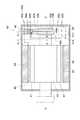
図2は、本実施形態の同期電動機を例示する部分断面図である。
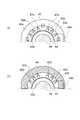
図3は、図2の同期電動機のA−A’矢視断面図である。
図2に示すように、本実施形態の同期電動機62は、界磁巻線41と、ブラシ42a,42bと、直流入力変換器50と、出力端子52a,52bと、を備える。
第1の実施形態において説明した同期電動機2と同一の構成要件については、同一の符号を付して詳細な説明を適宜省略する。(Second Embodiment)
FIG. 2 is a partial cross-sectional view illustrating the synchronous motor of this embodiment.
FIG. 3 is a cross-sectional view taken along the line AA ′ of the synchronous motor of FIG.
As shown in FIG. 2, the
The same components as those of the
図2では、同期電動機62の固定子45およびフレーム46の断面を示し、他の部分の側面を示している。図2に示すように、界磁巻線41は、同期電動機62の回転子44に固定されるように設けられている。回転子44は、中心線C−C’を回転軸にして回転する。したがって、同期電動機2の運転中には、界磁巻線41は、中心線C−C’を軸にして回転子44とともに回転している。界磁巻線41の一端は、コレクタリング43aに電気的に接続され、他端は、コレクタリング43bに電気的に接続されている。なお、界磁巻線41は、中心線C−C’に垂直な方向に磁界を発生するように巻回されている。 In FIG. 2, the cross section of the
固定子巻線40は、鉄心である固定子45のスリットに挿入されている。固定子45は、フレーム46に固定されている。 The stator winding 40 is inserted into a slit of a
図3(a)に示すように、ブラシ42aは、ブラシホルダ47aに挿入されブラシ42aの先端がコレクタリング43aに接触するように、フレーム46に固定されている。フレーム46は、固定されているので、ブラシ42aは同期電動機2に対して固定されている。ブラシ42aは、同期電動機2の運転中には、コレクタリング43aに接触しているので、接触部が摩耗する。そのため、ブラシ42aとコレクタリング43aとの接触抵抗を低減するために、この例では、ブラシ42aは、複数個をコレクタリング43aの周囲を適切な間隔だけ離間して配置されている。複数のブラシ42aは、並列に接続されている。図3(b)に示すように、界磁巻線41の他端には、複数のブラシ42bが並列に接続されている。複数のブラシ42bは、コレクタリング43bに接触することによって、電気的接続が図られている。複数のブラシ42bは、ブラシ42aと同様にそれぞれブラシホルダ47bに挿入され、フレーム46に固定されている。このように、固定子側に固定されているブラシ42aおよびブラシ42bは、回転する界磁巻線41の一端および他端にそれぞれ電気的に接続されることができる。 As shown in FIG. 3A, the
ブラシ42a,42bには、配線49a,49bの一端がそれぞれ接続されており、延伸された配線49a,49bの他端は、直流入力変換器50の入力端子51a,51bに電気的に接続されている。 One ends of
直流入力変換器50は、この例ではコレクタリング43a,43bの下部に配置され、フレーム46に固定されている。ブラシ42a,42bから延伸された配線49a,49bは、コレクタリング43a,43bの外周をとおって直流入力変換器50の入力端子51a,51bに電気的に接続される。 In this example, the
直流入力変換器50の入力端子51a,51bは、配線49a,49bによって、それぞれブラシ42a,42bに電気的に接続されている。ブラシ42a,42bは、それぞれコレクタリング43a,43bを介して界磁巻線41の両端に電気的に接続されているので、直流入力変換器50の入力には、界磁巻線41の両端の電圧が入力される。直流入力変換器50の出力端子52a,52bは、電力変換装置1の端子30c,30dを介して、制御回路30の温度演算部37の入力に接続される。直流入力変換器50は、直流電圧を入力して、入力した直流電圧値に比例した直流電圧を出力する。 The
直流入力変換器50の入力端子51a,51bは、上述のように界磁巻線41に電気的に接続されているので、別の配線によって端子64a,64bに接続され、外部の回路に接続される。具体的には、端子64a,64は、電力変換装置1の端子30a,30bを介して、制御回路30の界磁巻線整流回路34に電気的に接続される。 Since the
本実施形態の同期電動機2の作用および効果について説明する。
本実施形態の同期電動機2は、ブラシ42a,42bによって検出された界磁巻線41の両端の電圧を入力して、入力電圧に比例する電圧を出力電圧として出力する直流入力変換器50を備えているので、100Vを超える高電圧に達することがある界磁巻線41の両端の電圧を低電圧化して、そのまま制御回路30に入力することができる。また、同期電動機2は、第1の実施形態の電力変換装置1とともに用いることによって、制御回路30において、界磁巻線41の温度を計算することができるので、高い信頼性で動作させることができる。The operation and effect of the
The
以上説明した実施形態によれば、同期電動機を可変速制御する電力変換装置にて界磁巻線温度を含めた界磁諸量を監視することが可能となり、より安全な運転を継続させることができる。 According to the embodiment described above, it becomes possible to monitor the field quantities including the field winding temperature in the power converter that performs variable speed control of the synchronous motor, and to continue safer operation. it can.
以上、本発明のいくつかの実施形態を説明したが、これらの実施形態は、例として提示したものであり、発明の範囲を限定することは意図していない。これら新規な実施形態は、その他のさまざまな形態で実施されることが可能であり、発明の要旨を逸脱しない範囲で、種々の省略、置き換え、変更を行うことができる。これら実施形態やその変形は、発明の範囲や要旨に含まれるとともに、特許請求の範囲に記載された発明およびその等価物の範囲に含まれる。また、前述の各実施形態は、相互に組み合わせて実施することができる。 As mentioned above, although some embodiment of this invention was described, these embodiment is shown as an example and is not intending limiting the range of invention. These novel embodiments can be implemented in various other forms, and various omissions, replacements, and changes can be made without departing from the scope of the invention. These embodiments and modifications thereof are included in the scope and gist of the invention, and are included in the scope of the invention described in the claims and the equivalents thereof. Further, the above-described embodiments can be implemented in combination with each other.
1 電力変換装置、2,62 同期電動機、3 入力電源、10 整流回路、12 平滑回路、20 主回路、22 電流検出部、30 制御回路、31 電流制御回路、32 基準信号発生回路、33 ゲート駆動回路、34 界磁巻線整流回路、35 界磁制御回路、36 界磁電流検出部、37 温度演算部、38 記憶部、40 固定子巻線、41 界磁巻線、42a,42b ブラシ、43a,43b コレクタリング、44 回転子、45 固定子、46 フレーム、47a,47b ブラシホルダ、48a,48b 端子、49a,49b 配線、50 直流入力変換器、51a,51b 入力端子、52a,52b 出力端子 DESCRIPTION OF
Claims (4)
Translated fromJapanese界磁巻線を流れる電流を検出する電流検出部と、
前記界磁巻線の温度を計算するためのデータを格納する記憶部と、
前記データ、前記電流検出部によって検出された前記電流、およびブラシを介して検出された前記界磁巻線の両端の電圧である第1電圧にもとづいて、前記界磁巻線の温度を計算する演算部と、
を備えた電力変換装置。A power converter for driving a brushed synchronous motor,
A current detector for detecting the current flowing through the field winding;
A storage unit for storing data for calculating the temperature of the field winding;
The temperature of the field winding is calculated based on the data, the current detected by the current detection unit, and a first voltage that is a voltage across the field winding detected via a brush. An arithmetic unit;
The power converter provided with.
固定子に設けられ、前記回転子に設けられたコレクタリングを介して前記界磁巻線と電気的に接続されるブラシと、
前記ブラシを介して前記界磁巻線に電気的に接続され、前記界磁巻線の両端の電圧である第1電圧を入力して前記第1電圧に比例した第2電圧を出力する直流入力変換器と、
前記直流入力変換器の出力に電気的に接続され、前記界磁巻線の温度を計算するためのデータ、前記界磁巻線を流れる電流、および前記第2電圧にもとづいて、前記界磁巻線の温度を計算する演算部に電気的に接続される端子と、
を備えた同期電動機。A field winding provided on the rotor;
A brush provided on the stator and electrically connected to the field winding via a collector ring provided on the rotor;
DC input that is electrically connected to the field winding via the brush, inputs a first voltage that is a voltage across the field winding, and outputs a second voltage proportional to the first voltage. A converter,
The field winding electrically connected to the output of the DC input converter and based on data for calculating the temperature of the field winding, the current flowing through the field winding, and the second voltage. A terminal electrically connected to an arithmetic unit for calculating the temperature of the wire;
Synchronous motor with
Priority Applications (1)
| Application Number | Priority Date | Filing Date | Title |
|---|---|---|---|
| JP2015216741AJP6482028B2 (en) | 2015-11-04 | 2015-11-04 | Synchronous motor |
Applications Claiming Priority (1)
| Application Number | Priority Date | Filing Date | Title |
|---|---|---|---|
| JP2015216741AJP6482028B2 (en) | 2015-11-04 | 2015-11-04 | Synchronous motor |
Publications (2)
| Publication Number | Publication Date |
|---|---|
| JP2017093044Atrue JP2017093044A (en) | 2017-05-25 |
| JP6482028B2 JP6482028B2 (en) | 2019-03-13 |
Family
ID=58768804
Family Applications (1)
| Application Number | Title | Priority Date | Filing Date |
|---|---|---|---|
| JP2015216741AActiveJP6482028B2 (en) | 2015-11-04 | 2015-11-04 | Synchronous motor |
Country Status (1)
| Country | Link |
|---|---|
| JP (1) | JP6482028B2 (en) |
Citations (3)
| Publication number | Priority date | Publication date | Assignee | Title |
|---|---|---|---|---|
| EP0726632A1 (en)* | 1995-02-10 | 1996-08-14 | The Raymond Corporation | Lift truck with internal temperature monitor and system |
| JPH0919109A (en)* | 1995-06-28 | 1997-01-17 | Nishishiba Electric Co Ltd | Field coil overheat protector |
| JP2009165232A (en)* | 2007-12-28 | 2009-07-23 | Hitachi Ltd | Rotating electrical machine control device and rotating electrical machine device |
- 2015
- 2015-11-04JPJP2015216741Apatent/JP6482028B2/enactiveActive
Patent Citations (3)
| Publication number | Priority date | Publication date | Assignee | Title |
|---|---|---|---|---|
| EP0726632A1 (en)* | 1995-02-10 | 1996-08-14 | The Raymond Corporation | Lift truck with internal temperature monitor and system |
| JPH0919109A (en)* | 1995-06-28 | 1997-01-17 | Nishishiba Electric Co Ltd | Field coil overheat protector |
| JP2009165232A (en)* | 2007-12-28 | 2009-07-23 | Hitachi Ltd | Rotating electrical machine control device and rotating electrical machine device |
Also Published As
| Publication number | Publication date |
|---|---|
| JP6482028B2 (en) | 2019-03-13 |
Similar Documents
| Publication | Publication Date | Title |
|---|---|---|
| JP6353694B2 (en) | Deterioration diagnosis system | |
| EP2769462B1 (en) | Method and system for detecting a failed rectifier in an ac/dc converter | |
| JP5543981B2 (en) | Robust online stator winding fault identification system | |
| JP6333772B2 (en) | Synchronous motor temperature estimation device | |
| US8536839B2 (en) | Device and method for monitoring and/or analyzing rotors of electric machines in operation | |
| JP6480316B2 (en) | Motor control device | |
| KR101169797B1 (en) | Fault detecting system of stator winding of motor | |
| US20150364978A1 (en) | Electric Machine | |
| JP2012093169A (en) | Insulation deterioration detection device of motor | |
| JP2012233826A (en) | Motor control device and motor insulation deterioration detection method | |
| CN102288801A (en) | Measuring of earth fault current | |
| KR20100057845A (en) | Method and apparatus for determining a field current in brushless electrical machines | |
| CA2905668C (en) | Method and system for determining core losses in a permanent magnet synchronous motor | |
| WO2018072969A1 (en) | A method for detecting a fault in an electrical machine | |
| US11346885B2 (en) | Winding interlayer short-circuit detection apparatus and winding interlayer short-circuit detection method | |
| JP6412144B2 (en) | Insulation diagnostic system or rotating machine | |
| JP2020114149A (en) | Short-circuit detection device for detecting interlayer short-circuit between of winding in motor, motor control device, and numerical control system | |
| JP6482028B2 (en) | Synchronous motor | |
| He et al. | Diagnosis of stator short-circuit faults in an IPM synchronous machine using a space-vector pendulous oscillation method | |
| JP6900504B2 (en) | An electric machine equipped with a rotor measuring unit for measuring the rotor parameters of the electric machine. | |
| KR101193957B1 (en) | Method and System for Calculating Torque of Induction Motors Using Current Spectrum and Method and System For Fault Diagnosis of Induction Motors Using the same | |
| JP2005039891A (en) | Control unit of synchronous machine | |
| EP4510441A1 (en) | Power generation device | |
| JP2001153934A (en) | Field winding interlayer short circuit tester | |
| JP2013162727A (en) | Failure detection device and failure detection method of generator excitation device |
Legal Events
| Date | Code | Title | Description |
|---|---|---|---|
| A621 | Written request for application examination | Free format text:JAPANESE INTERMEDIATE CODE: A621 Effective date:20171109 | |
| A977 | Report on retrieval | Free format text:JAPANESE INTERMEDIATE CODE: A971007 Effective date:20180827 | |
| A131 | Notification of reasons for refusal | Free format text:JAPANESE INTERMEDIATE CODE: A131 Effective date:20180829 | |
| A521 | Request for written amendment filed | Free format text:JAPANESE INTERMEDIATE CODE: A523 Effective date:20181026 | |
| TRDD | Decision of grant or rejection written | ||
| A01 | Written decision to grant a patent or to grant a registration (utility model) | Free format text:JAPANESE INTERMEDIATE CODE: A01 Effective date:20190206 | |
| A61 | First payment of annual fees (during grant procedure) | Free format text:JAPANESE INTERMEDIATE CODE: A61 Effective date:20190206 | |
| R150 | Certificate of patent or registration of utility model | Ref document number:6482028 Country of ref document:JP Free format text:JAPANESE INTERMEDIATE CODE: R150 | |
| R250 | Receipt of annual fees | Free format text:JAPANESE INTERMEDIATE CODE: R250 | |
| R250 | Receipt of annual fees | Free format text:JAPANESE INTERMEDIATE CODE: R250 | |
| R250 | Receipt of annual fees | Free format text:JAPANESE INTERMEDIATE CODE: R250 | |
| R250 | Receipt of annual fees | Free format text:JAPANESE INTERMEDIATE CODE: R250 |